EP2808437A1 - Sèche-linge doté d'un échangeur de chaleur - Google Patents
Sèche-linge doté d'un échangeur de chaleur Download PDFInfo
- Publication number
- EP2808437A1 EP2808437A1 EP14168788.9A EP14168788A EP2808437A1 EP 2808437 A1 EP2808437 A1 EP 2808437A1 EP 14168788 A EP14168788 A EP 14168788A EP 2808437 A1 EP2808437 A1 EP 2808437A1
- Authority
- EP
- European Patent Office
- Prior art keywords
- air
- drum
- heat exchanger
- laundry dryer
- air duct
- Prior art date
- Legal status (The legal status is an assumption and is not a legal conclusion. Google has not performed a legal analysis and makes no representation as to the accuracy of the status listed.)
- Granted
Links
Images



Classifications
-
- D—TEXTILES; PAPER
- D06—TREATMENT OF TEXTILES OR THE LIKE; LAUNDERING; FLEXIBLE MATERIALS NOT OTHERWISE PROVIDED FOR
- D06F—LAUNDERING, DRYING, IRONING, PRESSING OR FOLDING TEXTILE ARTICLES
- D06F58/00—Domestic laundry dryers
- D06F58/20—General details of domestic laundry dryers
- D06F58/24—Condensing arrangements
-
- D—TEXTILES; PAPER
- D06—TREATMENT OF TEXTILES OR THE LIKE; LAUNDERING; FLEXIBLE MATERIALS NOT OTHERWISE PROVIDED FOR
- D06F—LAUNDERING, DRYING, IRONING, PRESSING OR FOLDING TEXTILE ARTICLES
- D06F58/00—Domestic laundry dryers
- D06F58/02—Domestic laundry dryers having dryer drums rotating about a horizontal axis
Definitions
- the present invention relates to a laundry dryer, comprising: a body having air discharge openings in an upper region; a laundry drum disposed in the body, a heat exchanger to condense process air from the drum, said heat exchanger being positioned in the body below the drum and having a cooling air outlet.
- lint is typically released from the laundry and may, in small quantities, end up in the body of the laundry dryer. There, it mostly deposits on a floor or bottom. Over a lifetime of the laundry dryer, the lint is likely to accumulate. Lint is potentially flammable and might, under extreme conditions, be ignited within the body.
- Document WO 2011/154439 A1 relates to a laundry dryer including a body having two side walls or side panels, a front wall or panel and a rear wall or panel, a drum disposed in the body, into which the laundry to be dried is placed, a condenser or heat exchanger providing the dehumidification of the cooling air used in the drying process by condensing it, a base unit disposed under the drum, supporting the motor, the fan, the condenser and other elements required for the drying process, a first opening disposed on the base unit, providing the cooling air passing through the condenser to be delivered into the body, a second opening disposed on the rear wall, providing the cooling air delivered into the body to be discharged to the outer environment, and wherein vibration and noise occurring during the discharge of the cooling air passed over the condenser to the outer environment are reduced.
- a laundry dryer is provided as defined in the independent claim attached.
- Advantageous embodiments and developments of the invention are defined in dependent claims attached, the subsequent description and the drawing attached.
- a laundry dryer includes a body having air discharge openings in an upper region, a laundry drum disposed in the body, a heat exchanger to condense process air from the drum, the heat exchanger being positioned in the body below the drum and having a cooling air outlet, and an air duct having an air inlet connected to the cooling air outlet and an air outlet which is positioned above the heat exchanger, the air duct being arranged to discharge cooling air from the air outlet in an upward direction into the body.
- cooling air is not being discharged in the vicinity of the floor or bottom anymore but is discharged into the body at a significant distance above the floor, and away from the floor.
- This discharged air can escape the body through the air discharge openings in the upper region so that the discharged air is not re-directed towards the floor.
- lint accumulated on the floor is not aerated by the cooling air which mitigates the spreading of fire or flames through the lint.
- burning lint is not being carried away by the cooling air into other regions of the dryer or through air discharge openings.
- such an air duct can be realized in a cost-effective manner.
- the other components of the dryer do not need to be significantly adapted or changed, if at all.
- the air duct can achieve noise reduction and can improve process performance in a simple and cost-effective manner.
- the laundry dryer can be constructed as a tumble dryer having a rotatable drum.
- the rotatable drum may be actuated or driven by a motor. This motor may in particular be positioned on the floor of the dryer.
- the laundry dryer can be a 'front loading dryer' having a loading port in a front side of the dryer.
- the drum may be rotatable around a horizontal rotation axis.
- the drum may in particular be rotatably attached to a first bearing shield at the front and / or a second bearing shield at the rear.
- the body or housing may include a front panel (or "wall” or “side”), two side panels, and a rear panel.
- the front panel may include an opening for the loading port.
- the air discharge openings of the body are advantageously located at the rear panel, in particular solely at the rear panel.
- the air discharge openings can be mainly located in an upper region of the body.
- the air discharge openings representing at least 80%, preferably 90%, preferably 100%, of a cross-sectional area of all air discharge openings may be located in an upper region of the body.
- the other air discharge openings, if any, may be located in a complementary lower region of the body.
- all air discharge openings may be located in an upper region of the body. In the event of a self-combustion of lint, this prevents that oxygen-rich ambient air is supplied to the floor region in great quantities thus slowing a spread of flames and/or preventing a stack-effect.
- An "upper region” of the body may in particular relate to a region that is located at least within the upper 2/3 of the height of the body.
- the air discharge openings are mainly (i.e. representing at least 80%, preferably 90%, preferably 100%, of a cross-sectional area) located above at least 1/3 of the height of the body starting from the floor or bottom.
- the heat exchanger may in particular be an air/air heat exchanger having a first air channel to guide cooling air and a second air channel to guide process air to enable a thermal exchange between the cooling air and the process air.
- the heat exchanger may thus in particular include a cooling air inlet, a cooling air outlet, a process air inlet, and a process air outlet. Since the process air coming from the drum is typically warmer than the cooling air, heat is transferred from the process air to the cooling air so that the process air is cooled down and moisture of the cooling air is condensed.
- the heat exchanger can thus also be regarded as an air-cooled process air condenser.
- the laundry dryer includes a closed-loop process air channel that re-circulates process air from and to the drum.
- the process air channel includes or is functionally connected to the heat exchanger.
- the process air channel may include or may be functionally connected to a ventilator or fan for moving the process air within the process air channel and/or a heating means downstream of the heat exchanger for heating the condensed process air prior to re-entering the drum.
- the heat exchanger may be positioned below the drum as a stand-alone device.
- the heat exchanger can be made part of a base unit or base module.
- the base unit may additionally include other functional elements for operating the dryer such as the motor for rotating the drum, the ventilator or fan, a condensate reservoir, etc.
- the functional elements may be attached to a common mounting, e.g. a mounting frame.
- the base unit may include plastic parts. Lint will then typically accumulate on the base unit.
- the base unit may be regarded as the floor of the body interior.
- the cooling air outlet of the heat exchanger is connected to the air inlet of the air duct and advantageously has an airtight connection between the cooling air outlet of the heat exchanger and the air inlet of the air duct to prevent leakage.
- the cooling air outlet and/or the air inlet may include a sealing.
- the body has a front panel, two side panels, and a rear panel, with the discharge openings of the body being located in an upper region of the rear panel, and with the air duct being arranged to discharge cooling air along one of the side panels.
- the air duct can be arranged to discharge cooling air between the one of the side panels and the laundry drum.
- a high volume of cooling air can directly flow into a region within the body above the drum and spread there.
- the drum then acts as a barrier to prevent this cooling air from flowing back down towards the floor or bottom of the body in large quantities. Therefore, this cooling air can effectively flow from this region through the discharge openings and out of the body.
- the air duct can be arranged to create a flow of cooling air substantially parallel along the one of the side panels. This enables a strong laminar air flow between the drum and the side panel without blowing onto the drum.
- the drum is not significantly cooled by the cooling air which in turn increases the process performance and energy efficiency.
- the side panel is not or not significantly hit or stressed by the cooling air which reduces noise, e.g. caused by vibrations of the side panel.
- This embodiment is advantageous when the laundry dryer is constructed in the form of a front-loading laundry dryer having a horizontally aligned drum since such a drum is a particularly effective air barrier.
- substantially parallel may relate to "parallel” or “slightly inclined”.
- “Slightly inclined” may in particular relate to an inclination having an inclination angle (e.g. with the side panel) of less than 25°, in particular of less than 10°, in particular of less than 5%.
- An inclination angle of 0° indicates a parallel alignment.
- the at least one air outlet of the air duct can be inclined towards the side panel. This may lead to an air flow of cooling air discharged from the at least one air outlet that is inclined towards the side panel.
- the inclination angle is less than 60°, in particular less than 45°.
- an inclination angle of the air outlet may be larger than an inclination angle of the discharged air flow.
- the cooling air discharged from the air duct is at least substantially lami-nar. This avoids turbulences that could aerate the lint. Also a warm air around the drum is not significantly disturbed to maintain energy effectiveness.
- the at least one air outlet of the air duct may have a height between 20 mm and 40 mm. Currently preferred is a height of 30 mm.
- the air duct can have a height between 200 mm and 300 mm. This is a particular effective to prevent lint to be aerated by the cooling air which at the same time is easy to integrate into the dryer.
- the height of the air duct is in particular an effective height or functional height between its air inlet and its air outlet and thus the height that the cooling air is travelling between the air inlet and the air outlet.
- the air duct as a device may have a greater overall height, e.g. because of projecting fastening means etc.
- the air duct preferably guides cooling air from the level of the heat exchanger to a level between 200 mm and 300 mm further upwards.
- the air duct has a (effective) height between 200 mm and 250 mm.
- a height of 220 mm is preferred.
- the laundry dryer can be constructed in the form of a front-loading laundry dryer having a horizontally aligned drum, with the air outlet of the air duct being located between the drum and a side panel of the body below a largest width of the drum, and with the air discharge openings being located above the largest width of the drum.
- the air duct may reach through the gap between the drum at its largest width and the side panel such that the air outlet is located above the largest width of the drum. This may be a particularly effective way to prevent back-flow of the cooling air to the floor, in particular to a base unit.
- the discharge openings of the body can be mainly positioned in an upper half of the body, i.e. in the upper half of the height.
- the discharge openings of the body are mainly positioned above a half of the height of the body or panel.
- the discharge openings of the body can be mainly, in particular solely, located in an upper 40 % of a height of the body.
- the at least one air outlet of the air duct is located not more than 50 mm below the discharge openings of the body.
- the at least one air outlet of the air duct is located no more than 10 mm below the discharge openings opening of the body.
- a cross-sectional area of the at least one air outlet of the air duct can be equal or greater than a cross-sectional area of the air inlet of the air duct. This prevents the cooling air flowing through the air duct from gaining speed at the air outlet which might cause a whistling sound.
- this embodiment helps with noise reduction or prevention.
- the air duct may be made of one piece or may be a preassembled, multiple-piece device.
- the air duct is preferably made of plastic, e.g. made by die casting.
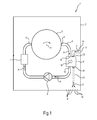
- Fig.1 shows a sketch of selected parts of a laundry dryer 1 embodied as a tumble dryer 1 for drying laundry.
- the tumble dryer 1 comprises a housing or body 2, in which resides a rotatable drum 3.
- the drum 3 is a front-loadable drum that rotates around a horizontal axis H.
- the drum 3 is connected to and part of a closed-loop process air channel 4 that re-circulates process air A from and to the drum 3.
- the process air channel 4 comprises a condenser in form of a heat exchanger 5 for cooling the process air A.
- the process air channel 4 also comprises a ventilator 6 or fan for moving the process air A within the process air channel 4 and comprises a heating means 7, e.g. an electric heater, downstream of the heat exchanger 5 for heating the process air A prior to re-entering the drum 3.
- a heating means 7 e.g. an electric heater
- the drum 3 is loaded with wet laundry (not shown).
- the heating means 7 creates warm and dry process air A that flows into the rotating drum 3.
- moisture can evaporate from the laundry.
- the resulting warm and moisture-rich process air A flows out of the drum 3 into the heat exchanger 5.
- the process air A is cooled down, and the moisture is condensed. Downstream of the heat exchanger 5, the process air A is again dry and comparatively cool. This dry and (comparatively) cool process air A then flows again to the heating means 7, and the circle starts anew.
- the heat exchanger 5 comprises a process air inlet 8 connected to an outlet port 9 of the drum 3, a process air outlet 10 connected to an inlet port 11 of the drum 3 via the ventilator 6 and the heating means 7, a cooling air inlet 12 connected to an air intake port 13 of the body 2 via an air intake duct 14, and a cooling air outlet 15 opening into the body 2.
- the body 2 During operation, ambient air is sucked into the air intake port 13 of the body 2 (e.g. by a ventilator or fan, not shown) and flows through the air intake duct 14 to the cooling air inlet 12 of the heat exchanger 5, through the heat exchanger 5 and is then discharged through the cooling air outlet 15.
- the body 2 comprises multiple air discharge openings 16.
- the cooling air outlet 17 directly opens into the body 2 such that the cooling air C blows onto or closely next to lint (not shown) that has been accumulated on a floor or bottom of the tumble dryer.
- burning lint is aerated and may further be blown around the body 2 and possibly out through the discharge openings 16 by the cooling air C discharged from the cooling air outlet 15.
- the tumble dryer 1 shown has an (inner) air duct 17 connected to the cooling air outlet 15 that guides the cooling air C discharged from the cooling air outlet 15 to a region of the body 2 where it does not adversely affect burning lint anymore.
- Fig.2 shows an oblique view of a partial cut-out of a more detailed representation of the tumble dryer 1.
- the body 2 comprises a front panel 18, two side panels of which a left side panel 19 is shown, a rear panel 20, a top side 21t, and a bottom side 21 b.
- the bottom side 21 b is covered by a base unit 22 that, inter alia, comprises the heat exchanger 5, the air intake duct 14, a radial fan 23, a motor for rotating the drum 3 (not shown).
- the radial fan 23 is used for moving the cooling air C from the air intake port 13 of the body 2 through the air intake duct 14 to the heat exchanger 5.
- the air intake port 13 is covered by a mesh 24.
- the tumble dryer 1 further comprises a loading port 25 in the front panel 18 for loading the laundry into the drum 3, a door 26 for closing the loading port 25, a control panel 27 having several control elements 28 and a display 29.
- the drum 3 is rotatably attached to a bearing shield 32.
- the air discharge openings 16 are formed as horizontal slots and are located at the rear panel 20. In particular, all air discharge openings 16 are located in an upper 40% of the height of the body 2 and of the rear panel 20, respectively. Thus, the air discharge openings 16 are also positioned above the largest width L of the drum 3. They are further located around the bearing shield 32.
- the cooling air outlet 15 of the heat exchanger 5 is located on an upper side of the heat exchanger 5 and below the drum 3.
- the air duct 17 is attached to the heat exchanger 5 in such a way that its air inlet 30 is pressed onto the cooling air outlet 15 of the heat exchanger 5 in an airtight manner.
- the air inlet 30 and the air outlet 15 are spaced apart in an airtight manner against the surrounding top area of the base unit 22.
- Cooling air C flows upwards through the air duct 17 in a substantially vertical direction and exits the air duct 17 at an air outlet 31.
- the air duct 17 is located below the largest width L of the drum 3 and substantially above the base unit 22. Its air outlet 31 is located between a lower half of the drum 3 and the left side panel 19, facing the left side panel 19 in an oblique manner.
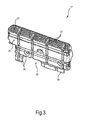
- the air duct 17 is shown in greater detail in Fig.3 with view onto a front side 33, Fig.4 with view onto a rear side 34, and Fig.5 as a side view with air duct 17 being located next to the left side panel 19.
- the air duct 17 is of a roughly cuboid shape and made of plastic.
- the air inlet 30 is located at a bottom side of the air duct 17. From the bottom side are protruding a clip 35 and a plate 36 to attach the air duct 17 to the heat exchanger 5.
- the air duct 17 has an effective height H1 for guiding the cooling air C about 220 mm in an upward direction.
- a height H2 of the air outlet 31 is about 30 mm. Because the air duct 17 is laterally closed along its effective height H1, the cooling air C flows from the level of the heat exchanger 5 to a level 220 mm higher.
- the air outlet 31 comprises a horizontal series of vertically aligned slots 37.
- a rear side 34 of the air duct 17 is curved at an end section 38.
- the cooling air C is discharged from the air outlet 31 with a respective inclination angle.
- This inclination angle is generally smaller than the inclination angle ⁇ of the air outlet 31, e.g. less than 25°, in particular less than 10°.
- the inclination angle of the cooling air C at the air outlet 31 is decreasing farther from the end section 38 or nearer to the side panel 19.
- the inclination angle ⁇ mostly causes the effect that the flow of cooling air C is narrower than the air outlet 31, i.e. more concentrated towards the left side panel 19. Therefore, the flow of cooling air C can pass a gap between the drum 3 at its largest width L and the left side panel 19 without significantly hitting the drum 3 and/or disturbing a layer of warm air around the drum 3. Hence, energy efficiency is improved.
- the inclination angle ⁇ of the air outlet 31 towards the left side panel 19 ⁇ is not so large that it causes a noisy vibration of the left side panel 19. Also, it is so small that there is created a substantially laminar flow of cooling air C that is pointed upwards and that is flowing essentially parallel to the left side panel 19.
- cooling air C can be discharged out of the body 2 through the air discharge openings 16 in the rear panel 20.
- the drum 3 acts as a barrier and prevents strong currents of oxygen-rich air flowing from the region of the body 2 above the drum 3 towards the base unit 22. Further noise generation is also prevented by the fact that a cross-sectional area of the air outlet 31 of the air duct 17 is equal or greater than a cross-sectional area of the air inlet 30 of the air duct 17.
- the air duct 17 may e.g. be a one-piece element or is a preassembled, multiple-piece element.
- the air duct is preferably made of plastic, e.g. made by die casting.
Landscapes
- Engineering & Computer Science (AREA)
- Textile Engineering (AREA)
- Detail Structures Of Washing Machines And Dryers (AREA)
Applications Claiming Priority (1)
| Application Number | Priority Date | Filing Date | Title |
|---|---|---|---|
| US13/903,015 US9677216B2 (en) | 2013-05-28 | 2013-05-28 | Laundry dryer having a heat exchanger |
Publications (2)
| Publication Number | Publication Date |
|---|---|
| EP2808437A1 true EP2808437A1 (fr) | 2014-12-03 |
| EP2808437B1 EP2808437B1 (fr) | 2017-02-01 |
Family
ID=50731981
Family Applications (1)
| Application Number | Title | Priority Date | Filing Date |
|---|---|---|---|
| EP14168788.9A Active EP2808437B1 (fr) | 2013-05-28 | 2014-05-19 | Sèche-linge doté d'un échangeur de chaleur |
Country Status (2)
| Country | Link |
|---|---|
| US (1) | US9677216B2 (fr) |
| EP (1) | EP2808437B1 (fr) |
Cited By (1)
| Publication number | Priority date | Publication date | Assignee | Title |
|---|---|---|---|---|
| US20160376744A1 (en) * | 2014-03-14 | 2016-12-29 | Haier Group Corporation | Dryer or washer dryer |
Families Citing this family (2)
| Publication number | Priority date | Publication date | Assignee | Title |
|---|---|---|---|---|
| CN105986454A (zh) * | 2015-02-04 | 2016-10-05 | 青岛海尔洗衣机有限公司 | 一种空气冷凝器及干衣机 |
| US10612184B2 (en) * | 2016-03-15 | 2020-04-07 | The Research Foundation For Suny | Hydronic drying machine |
Citations (4)
| Publication number | Priority date | Publication date | Assignee | Title |
|---|---|---|---|---|
| KR20050017282A (ko) * | 2003-08-12 | 2005-02-22 | 엘지전자 주식회사 | 의류건조기의 응축기 |
| EP1832678A1 (fr) * | 2006-03-06 | 2007-09-12 | Electrolux Home Products Corporation N.V. | Sèche-linge domestique économisant l'énergie |
| DE102009030286A1 (de) * | 2008-07-02 | 2010-01-21 | Whirlpool Corp., Benton Harbor | Verfahren zum Entfernen von Ablagerungen in einem Chemikalien ausgebenden Wäschetrockner |
| WO2011154439A1 (fr) | 2010-06-08 | 2011-12-15 | Arcelik Anonim Sirketi | Sécheur |
Family Cites Families (9)
| Publication number | Priority date | Publication date | Assignee | Title |
|---|---|---|---|---|
| US3419969A (en) * | 1967-08-23 | 1969-01-07 | Challenge Cook Bros Inc | Tumbler dryer |
| JPH0663294A (ja) * | 1992-08-20 | 1994-03-08 | Matsushita Electric Ind Co Ltd | 熱交換型送風機 |
| US5257468A (en) * | 1992-09-14 | 1993-11-02 | Mario Lebrun | Automatic dryer air outlet hose quick-disconnect coupling |
| KR100330814B1 (ko) * | 2000-11-22 | 2002-04-03 | (주)씨디에스글로벌 | 모든 가연성 물질을 초 고온, 고속으로 연소시키는 연소방법 |
| US20070193058A1 (en) * | 2006-02-23 | 2007-08-23 | Zarembinski Thomas P | Drying cabinet and ventilation system |
| DE102006031353A1 (de) * | 2006-07-06 | 2008-01-17 | BSH Bosch und Siemens Hausgeräte GmbH | Hausgerät zur Pflege von Wäschestücken und Verfahren zum Leiten von Kühlluft in einem solchen Hausgerät |
| KR100826535B1 (ko) * | 2007-02-20 | 2008-05-02 | 엘지전자 주식회사 | 필터 청소장치 및 이를 구비한 덕트리스 건조기 |
| EP2204487A1 (fr) * | 2008-12-30 | 2010-07-07 | Electrolux Home Products Corporation N.V. | Appareil domestique pour sécher les vêtements |
| KR102100473B1 (ko) * | 2013-04-30 | 2020-04-13 | 엘지전자 주식회사 | 폐열 회수수단을 갖는 의류처리장치 |
-
2013
- 2013-05-28 US US13/903,015 patent/US9677216B2/en active Active
-
2014
- 2014-05-19 EP EP14168788.9A patent/EP2808437B1/fr active Active
Patent Citations (4)
| Publication number | Priority date | Publication date | Assignee | Title |
|---|---|---|---|---|
| KR20050017282A (ko) * | 2003-08-12 | 2005-02-22 | 엘지전자 주식회사 | 의류건조기의 응축기 |
| EP1832678A1 (fr) * | 2006-03-06 | 2007-09-12 | Electrolux Home Products Corporation N.V. | Sèche-linge domestique économisant l'énergie |
| DE102009030286A1 (de) * | 2008-07-02 | 2010-01-21 | Whirlpool Corp., Benton Harbor | Verfahren zum Entfernen von Ablagerungen in einem Chemikalien ausgebenden Wäschetrockner |
| WO2011154439A1 (fr) | 2010-06-08 | 2011-12-15 | Arcelik Anonim Sirketi | Sécheur |
Cited By (2)
| Publication number | Priority date | Publication date | Assignee | Title |
|---|---|---|---|---|
| US20160376744A1 (en) * | 2014-03-14 | 2016-12-29 | Haier Group Corporation | Dryer or washer dryer |
| US9976249B2 (en) * | 2014-03-14 | 2018-05-22 | Haier Group Corporation | Dryer or washer dryer |
Also Published As
| Publication number | Publication date |
|---|---|
| EP2808437B1 (fr) | 2017-02-01 |
| US9677216B2 (en) | 2017-06-13 |
| US20140352166A1 (en) | 2014-12-04 |
Similar Documents
| Publication | Publication Date | Title |
|---|---|---|
| EP3045582B1 (fr) | Séchoir | |
| EP3045581B1 (fr) | Séchoir | |
| JP5460921B2 (ja) | 浴室乾燥機 | |
| CN103906874A (zh) | 具有热泵的衣物处理设备 | |
| US7093377B2 (en) | Laundry dryer and an air inlet structure thereof | |
| KR20070081440A (ko) | 세탁 건조기 | |
| CN106661815B (zh) | 热泵式衣物干燥机 | |
| JP7079860B2 (ja) | 高放熱ドライヤ | |
| US9845566B2 (en) | Clothes treating apparatus with heat recovery device | |
| EP2808437B1 (fr) | Sèche-linge doté d'un échangeur de chaleur | |
| JP6616594B2 (ja) | 衣類乾燥機 | |
| KR20250108569A (ko) | 의류건조기 | |
| EP1516953B1 (fr) | Sèche-linge domestique silencieux à condensation | |
| EP1865103B1 (fr) | Sèche-linge avec système de réduction du bruit | |
| JP5235711B2 (ja) | 加熱調理器 | |
| JP2006212265A (ja) | 乾燥機 | |
| JP2014184369A (ja) | 除湿機 | |
| JP5591635B2 (ja) | ランドリー機器 | |
| JP6545935B2 (ja) | 衣類乾燥機 | |
| EP2840181A1 (fr) | Sèche-linge | |
| JP5597440B2 (ja) | 洗濯乾燥機 | |
| JP2020018915A (ja) | 衣類乾燥機 | |
| JP6023969B2 (ja) | 浴室換気乾燥機 | |
| CN104704159B (zh) | 包括空气冷却的冷凝器的洗衣及干燥机 | |
| CN115897186A (zh) | 烘干设备的烘干系统及烘干设备 |
Legal Events
| Date | Code | Title | Description |
|---|---|---|---|
| PUAI | Public reference made under article 153(3) epc to a published international application that has entered the european phase |
Free format text: ORIGINAL CODE: 0009012 |
|
| 17P | Request for examination filed |
Effective date: 20140519 |
|
| AK | Designated contracting states |
Kind code of ref document: A1 Designated state(s): AL AT BE BG CH CY CZ DE DK EE ES FI FR GB GR HR HU IE IS IT LI LT LU LV MC MK MT NL NO PL PT RO RS SE SI SK SM TR |
|
| AX | Request for extension of the european patent |
Extension state: BA ME |
|
| RAP1 | Party data changed (applicant data changed or rights of an application transferred) |
Owner name: BSH HAUSGERAETE GMBH |
|
| R17P | Request for examination filed (corrected) |
Effective date: 20150603 |
|
| RBV | Designated contracting states (corrected) |
Designated state(s): AL AT BE BG CH CY CZ DE DK EE ES FI FR GB GR HR HU IE IS IT LI LT LU LV MC MK MT NL NO PL PT RO RS SE SI SK SM TR |
|
| 17Q | First examination report despatched |
Effective date: 20151015 |
|
| GRAP | Despatch of communication of intention to grant a patent |
Free format text: ORIGINAL CODE: EPIDOSNIGR1 |
|
| INTG | Intention to grant announced |
Effective date: 20160922 |
|
| GRAS | Grant fee paid |
Free format text: ORIGINAL CODE: EPIDOSNIGR3 |
|
| GRAA | (expected) grant |
Free format text: ORIGINAL CODE: 0009210 |
|
| AK | Designated contracting states |
Kind code of ref document: B1 Designated state(s): AL AT BE BG CH CY CZ DE DK EE ES FI FR GB GR HR HU IE IS IT LI LT LU LV MC MK MT NL NO PL PT RO RS SE SI SK SM TR |
|
| REG | Reference to a national code |
Ref country code: GB Ref legal event code: FG4D |
|
| REG | Reference to a national code |
Ref country code: CH Ref legal event code: EP Ref country code: AT Ref legal event code: REF Ref document number: 865706 Country of ref document: AT Kind code of ref document: T Effective date: 20170215 |
|
| REG | Reference to a national code |
Ref country code: IE Ref legal event code: FG4D |
|
| REG | Reference to a national code |
Ref country code: DE Ref legal event code: R096 Ref document number: 602014006473 Country of ref document: DE |
|
| REG | Reference to a national code |
Ref country code: NL Ref legal event code: MP Effective date: 20170201 |
|
| REG | Reference to a national code |
Ref country code: LT Ref legal event code: MG4D |
|
| REG | Reference to a national code |
Ref country code: AT Ref legal event code: MK05 Ref document number: 865706 Country of ref document: AT Kind code of ref document: T Effective date: 20170201 |
|
| PG25 | Lapsed in a contracting state [announced via postgrant information from national office to epo] |
Ref country code: IS Free format text: LAPSE BECAUSE OF FAILURE TO SUBMIT A TRANSLATION OF THE DESCRIPTION OR TO PAY THE FEE WITHIN THE PRESCRIBED TIME-LIMIT Effective date: 20170601 Ref country code: HR Free format text: LAPSE BECAUSE OF FAILURE TO SUBMIT A TRANSLATION OF THE DESCRIPTION OR TO PAY THE FEE WITHIN THE PRESCRIBED TIME-LIMIT Effective date: 20170201 Ref country code: LT Free format text: LAPSE BECAUSE OF FAILURE TO SUBMIT A TRANSLATION OF THE DESCRIPTION OR TO PAY THE FEE WITHIN THE PRESCRIBED TIME-LIMIT Effective date: 20170201 Ref country code: GR Free format text: LAPSE BECAUSE OF FAILURE TO SUBMIT A TRANSLATION OF THE DESCRIPTION OR TO PAY THE FEE WITHIN THE PRESCRIBED TIME-LIMIT Effective date: 20170502 Ref country code: NO Free format text: LAPSE BECAUSE OF FAILURE TO SUBMIT A TRANSLATION OF THE DESCRIPTION OR TO PAY THE FEE WITHIN THE PRESCRIBED TIME-LIMIT Effective date: 20170501 Ref country code: FI Free format text: LAPSE BECAUSE OF FAILURE TO SUBMIT A TRANSLATION OF THE DESCRIPTION OR TO PAY THE FEE WITHIN THE PRESCRIBED TIME-LIMIT Effective date: 20170201 |
|
| PG25 | Lapsed in a contracting state [announced via postgrant information from national office to epo] |
Ref country code: RS Free format text: LAPSE BECAUSE OF FAILURE TO SUBMIT A TRANSLATION OF THE DESCRIPTION OR TO PAY THE FEE WITHIN THE PRESCRIBED TIME-LIMIT Effective date: 20170201 Ref country code: LV Free format text: LAPSE BECAUSE OF FAILURE TO SUBMIT A TRANSLATION OF THE DESCRIPTION OR TO PAY THE FEE WITHIN THE PRESCRIBED TIME-LIMIT Effective date: 20170201 Ref country code: SE Free format text: LAPSE BECAUSE OF FAILURE TO SUBMIT A TRANSLATION OF THE DESCRIPTION OR TO PAY THE FEE WITHIN THE PRESCRIBED TIME-LIMIT Effective date: 20170201 Ref country code: BG Free format text: LAPSE BECAUSE OF FAILURE TO SUBMIT A TRANSLATION OF THE DESCRIPTION OR TO PAY THE FEE WITHIN THE PRESCRIBED TIME-LIMIT Effective date: 20170501 Ref country code: LU Free format text: LAPSE BECAUSE OF NON-PAYMENT OF DUE FEES Effective date: 20170531 Ref country code: NL Free format text: LAPSE BECAUSE OF FAILURE TO SUBMIT A TRANSLATION OF THE DESCRIPTION OR TO PAY THE FEE WITHIN THE PRESCRIBED TIME-LIMIT Effective date: 20170201 Ref country code: PL Free format text: LAPSE BECAUSE OF FAILURE TO SUBMIT A TRANSLATION OF THE DESCRIPTION OR TO PAY THE FEE WITHIN THE PRESCRIBED TIME-LIMIT Effective date: 20170201 Ref country code: AT Free format text: LAPSE BECAUSE OF FAILURE TO SUBMIT A TRANSLATION OF THE DESCRIPTION OR TO PAY THE FEE WITHIN THE PRESCRIBED TIME-LIMIT Effective date: 20170201 Ref country code: PT Free format text: LAPSE BECAUSE OF FAILURE TO SUBMIT A TRANSLATION OF THE DESCRIPTION OR TO PAY THE FEE WITHIN THE PRESCRIBED TIME-LIMIT Effective date: 20170601 Ref country code: ES Free format text: LAPSE BECAUSE OF FAILURE TO SUBMIT A TRANSLATION OF THE DESCRIPTION OR TO PAY THE FEE WITHIN THE PRESCRIBED TIME-LIMIT Effective date: 20170201 |
|
| PG25 | Lapsed in a contracting state [announced via postgrant information from national office to epo] |
Ref country code: IT Free format text: LAPSE BECAUSE OF FAILURE TO SUBMIT A TRANSLATION OF THE DESCRIPTION OR TO PAY THE FEE WITHIN THE PRESCRIBED TIME-LIMIT Effective date: 20170201 Ref country code: SK Free format text: LAPSE BECAUSE OF FAILURE TO SUBMIT A TRANSLATION OF THE DESCRIPTION OR TO PAY THE FEE WITHIN THE PRESCRIBED TIME-LIMIT Effective date: 20170201 Ref country code: CZ Free format text: LAPSE BECAUSE OF FAILURE TO SUBMIT A TRANSLATION OF THE DESCRIPTION OR TO PAY THE FEE WITHIN THE PRESCRIBED TIME-LIMIT Effective date: 20170201 Ref country code: EE Free format text: LAPSE BECAUSE OF FAILURE TO SUBMIT A TRANSLATION OF THE DESCRIPTION OR TO PAY THE FEE WITHIN THE PRESCRIBED TIME-LIMIT Effective date: 20170201 Ref country code: RO Free format text: LAPSE BECAUSE OF FAILURE TO SUBMIT A TRANSLATION OF THE DESCRIPTION OR TO PAY THE FEE WITHIN THE PRESCRIBED TIME-LIMIT Effective date: 20170201 |
|
| REG | Reference to a national code |
Ref country code: DE Ref legal event code: R097 Ref document number: 602014006473 Country of ref document: DE |
|
| PG25 | Lapsed in a contracting state [announced via postgrant information from national office to epo] |
Ref country code: DK Free format text: LAPSE BECAUSE OF FAILURE TO SUBMIT A TRANSLATION OF THE DESCRIPTION OR TO PAY THE FEE WITHIN THE PRESCRIBED TIME-LIMIT Effective date: 20170201 Ref country code: SM Free format text: LAPSE BECAUSE OF FAILURE TO SUBMIT A TRANSLATION OF THE DESCRIPTION OR TO PAY THE FEE WITHIN THE PRESCRIBED TIME-LIMIT Effective date: 20170201 |
|
| PLBE | No opposition filed within time limit |
Free format text: ORIGINAL CODE: 0009261 |
|
| STAA | Information on the status of an ep patent application or granted ep patent |
Free format text: STATUS: NO OPPOSITION FILED WITHIN TIME LIMIT |
|
| REG | Reference to a national code |
Ref country code: CH Ref legal event code: PL |
|
| 26N | No opposition filed |
Effective date: 20171103 |
|
| PG25 | Lapsed in a contracting state [announced via postgrant information from national office to epo] |
Ref country code: MC Free format text: LAPSE BECAUSE OF FAILURE TO SUBMIT A TRANSLATION OF THE DESCRIPTION OR TO PAY THE FEE WITHIN THE PRESCRIBED TIME-LIMIT Effective date: 20170201 |
|
| REG | Reference to a national code |
Ref country code: IE Ref legal event code: MM4A |
|
| PG25 | Lapsed in a contracting state [announced via postgrant information from national office to epo] |
Ref country code: LI Free format text: LAPSE BECAUSE OF NON-PAYMENT OF DUE FEES Effective date: 20170531 Ref country code: SI Free format text: LAPSE BECAUSE OF FAILURE TO SUBMIT A TRANSLATION OF THE DESCRIPTION OR TO PAY THE FEE WITHIN THE PRESCRIBED TIME-LIMIT Effective date: 20170201 Ref country code: CH Free format text: LAPSE BECAUSE OF NON-PAYMENT OF DUE FEES Effective date: 20170531 |
|
| REG | Reference to a national code |
Ref country code: FR Ref legal event code: ST Effective date: 20180131 |
|
| PG25 | Lapsed in a contracting state [announced via postgrant information from national office to epo] |
Ref country code: LU Free format text: LAPSE BECAUSE OF NON-PAYMENT OF DUE FEES Effective date: 20170519 |
|
| REG | Reference to a national code |
Ref country code: BE Ref legal event code: MM Effective date: 20170531 |
|
| PG25 | Lapsed in a contracting state [announced via postgrant information from national office to epo] |
Ref country code: IE Free format text: LAPSE BECAUSE OF NON-PAYMENT OF DUE FEES Effective date: 20170519 |
|
| PG25 | Lapsed in a contracting state [announced via postgrant information from national office to epo] |
Ref country code: FR Free format text: LAPSE BECAUSE OF NON-PAYMENT OF DUE FEES Effective date: 20170531 |
|
| PG25 | Lapsed in a contracting state [announced via postgrant information from national office to epo] |
Ref country code: BE Free format text: LAPSE BECAUSE OF NON-PAYMENT OF DUE FEES Effective date: 20170531 |
|
| PG25 | Lapsed in a contracting state [announced via postgrant information from national office to epo] |
Ref country code: MT Free format text: LAPSE BECAUSE OF NON-PAYMENT OF DUE FEES Effective date: 20170519 |
|
| GBPC | Gb: european patent ceased through non-payment of renewal fee |
Effective date: 20180519 |
|
| PG25 | Lapsed in a contracting state [announced via postgrant information from national office to epo] |
Ref country code: GB Free format text: LAPSE BECAUSE OF NON-PAYMENT OF DUE FEES Effective date: 20180519 |
|
| PG25 | Lapsed in a contracting state [announced via postgrant information from national office to epo] |
Ref country code: HU Free format text: LAPSE BECAUSE OF FAILURE TO SUBMIT A TRANSLATION OF THE DESCRIPTION OR TO PAY THE FEE WITHIN THE PRESCRIBED TIME-LIMIT; INVALID AB INITIO Effective date: 20140519 |
|
| PG25 | Lapsed in a contracting state [announced via postgrant information from national office to epo] |
Ref country code: CY Free format text: LAPSE BECAUSE OF FAILURE TO SUBMIT A TRANSLATION OF THE DESCRIPTION OR TO PAY THE FEE WITHIN THE PRESCRIBED TIME-LIMIT Effective date: 20170201 |
|
| PG25 | Lapsed in a contracting state [announced via postgrant information from national office to epo] |
Ref country code: MK Free format text: LAPSE BECAUSE OF FAILURE TO SUBMIT A TRANSLATION OF THE DESCRIPTION OR TO PAY THE FEE WITHIN THE PRESCRIBED TIME-LIMIT Effective date: 20170201 |
|
| PG25 | Lapsed in a contracting state [announced via postgrant information from national office to epo] |
Ref country code: TR Free format text: LAPSE BECAUSE OF FAILURE TO SUBMIT A TRANSLATION OF THE DESCRIPTION OR TO PAY THE FEE WITHIN THE PRESCRIBED TIME-LIMIT Effective date: 20170201 |
|
| PG25 | Lapsed in a contracting state [announced via postgrant information from national office to epo] |
Ref country code: AL Free format text: LAPSE BECAUSE OF FAILURE TO SUBMIT A TRANSLATION OF THE DESCRIPTION OR TO PAY THE FEE WITHIN THE PRESCRIBED TIME-LIMIT Effective date: 20170201 |
|
| REG | Reference to a national code |
Ref country code: DE Ref legal event code: R084 Ref document number: 602014006473 Country of ref document: DE |
|
| PGFP | Annual fee paid to national office [announced via postgrant information from national office to epo] |
Ref country code: DE Payment date: 20250531 Year of fee payment: 12 |