EP2808595B1 - Behälter und sein Herstellungsverfahren - Google Patents
Behälter und sein Herstellungsverfahren Download PDFInfo
- Publication number
- EP2808595B1 EP2808595B1 EP13169374.9A EP13169374A EP2808595B1 EP 2808595 B1 EP2808595 B1 EP 2808595B1 EP 13169374 A EP13169374 A EP 13169374A EP 2808595 B1 EP2808595 B1 EP 2808595B1
- Authority
- EP
- European Patent Office
- Prior art keywords
- tank
- main body
- base
- compartments
- component parts
- Prior art date
- Legal status (The legal status is an assumption and is not a legal conclusion. Google has not performed a legal analysis and makes no representation as to the accuracy of the status listed.)
- Active
Links
Images


Classifications
-
- F—MECHANICAL ENGINEERING; LIGHTING; HEATING; WEAPONS; BLASTING
- F01—MACHINES OR ENGINES IN GENERAL; ENGINE PLANTS IN GENERAL; STEAM ENGINES
- F01D—NON-POSITIVE DISPLACEMENT MACHINES OR ENGINES, e.g. STEAM TURBINES
- F01D25/00—Component parts, details, or accessories, not provided for in, or of interest apart from, other groups
- F01D25/18—Lubricating arrangements
-
- B—PERFORMING OPERATIONS; TRANSPORTING
- B21—MECHANICAL METAL-WORKING WITHOUT ESSENTIALLY REMOVING MATERIAL; PUNCHING METAL
- B21D—WORKING OR PROCESSING OF SHEET METAL OR METAL TUBES, RODS OR PROFILES WITHOUT ESSENTIALLY REMOVING MATERIAL; PUNCHING METAL
- B21D51/00—Making hollow objects
- B21D51/02—Making hollow objects characterised by the structure of the objects
- B21D51/10—Making hollow objects characterised by the structure of the objects conically or cylindrically shaped objects
-
- B—PERFORMING OPERATIONS; TRANSPORTING
- B21—MECHANICAL METAL-WORKING WITHOUT ESSENTIALLY REMOVING MATERIAL; PUNCHING METAL
- B21D—WORKING OR PROCESSING OF SHEET METAL OR METAL TUBES, RODS OR PROFILES WITHOUT ESSENTIALLY REMOVING MATERIAL; PUNCHING METAL
- B21D51/00—Making hollow objects
- B21D51/16—Making hollow objects characterised by the use of the objects
- B21D51/18—Making hollow objects characterised by the use of the objects vessels, e.g. tubs, vats, tanks, sinks, or the like
-
- F—MECHANICAL ENGINEERING; LIGHTING; HEATING; WEAPONS; BLASTING
- F16—ENGINEERING ELEMENTS AND UNITS; GENERAL MEASURES FOR PRODUCING AND MAINTAINING EFFECTIVE FUNCTIONING OF MACHINES OR INSTALLATIONS; THERMAL INSULATION IN GENERAL
- F16N—LUBRICATING
- F16N19/00—Lubricant containers for use in lubricators or lubrication systems
-
- F—MECHANICAL ENGINEERING; LIGHTING; HEATING; WEAPONS; BLASTING
- F02—COMBUSTION ENGINES; HOT-GAS OR COMBUSTION-PRODUCT ENGINE PLANTS
- F02C—GAS-TURBINE PLANTS; AIR INTAKES FOR JET-PROPULSION PLANTS; CONTROLLING FUEL SUPPLY IN AIR-BREATHING JET-PROPULSION PLANTS
- F02C7/00—Features, components parts, details or accessories, not provided for in, or of interest apart form groups F02C1/00 - F02C6/00; Air intakes for jet-propulsion plants
- F02C7/04—Air intakes for gas-turbine plants or jet-propulsion plants
Definitions
- the present invention relates to a method of manufacturing a reservoir.
- the present invention also relates to a fluid reservoir designed more particularly to be arranged in a reduced size environment.
- the tank is an oil tank designed to be arranged in a so-called "slim" nacelle.
- the oil tank is a component of the lubrication / cooling system of an aircraft engine for recovering and storing oil from the lubrication system.
- the oil reservoir is disposed between the nacelle and the inter-vein casing delimiting the primary vein and the secondary vein.
- slim New nacelles with a profile optimized to reduce drag have emerged.
- the space between the nacelle and the inter-vein crankcase is reduced with the result that the shape of the tank must be adapted.
- the tanks in the nacelles called “slim” are flat, that is to say they are wider than deep. These are either of aluminum and obtained by foundry, or steel welded. In both cases, the main faces, that is to say the flat faces of the tank, are held by a multitude of tie rods or retaining plates, also called baffles .
- the present invention aims to provide a tank specially adapted for reduced spaces and having a very good mechanical strength by its design and assembly process.
- the present invention further aims to provide a reservoir of reduced mass and obtained by an inexpensive process.
- the present invention also aims to provide a reservoir easily controllable by non-destructive testing.
- the present invention also relates to a turbomachine fluid reservoir, said reservoir comprising a main body provided with several compartments, a base closing the main body in its lower part and a lid closing the main body in its upper part, characterized in that that the main body, the base and the cover are essentially made of sheets, in addition to the main body is provided with several compartments and each compartment has at each of its ends at least one flange allowing an assembly end to end between the compartments.
- the present invention relates to a turbomachine comprising a fluid reservoir as described above.
- the present invention relates to a fluid reservoir designed more particularly to be arranged in a reduced size environment, and to its manufacturing process.
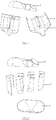
- the tank 1 according to the invention is an oil tank designed to be disposed in a turbomachine between the nacelle called "slim" 2 and the inter-vein crankcase 3 as schematized in FIG. figure 1 .
- Tank 1 shown in Figures 2 and 3 comprises a main body 4 closed at its respective ends by a base 6 and a lid 5.
- the main body 4 comprises compartments 7 of cylindrical shape or close to the cylinder, or ovoid shape.
- the section of the compartment may be variable along the longitudinal axis of the compartment. In this case, we will speak of a shape close to the cylinder rather than a cylindrical one.
- the main body 4 comprises at least two compartments 7. It may comprise two, three or more compartments (not shown) and this, depending on the available space and the required capacity.
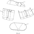
- the ends of the compartments comprise a rim 8, visible among others to Figures 4 and 5 which extends in a direction substantially perpendicular to the longitudinal axis of the compartment and communicates the compartments after assembly.
- the rim may take any form allowing an end-to-end connection between the compartments of the reservoir.
- each end has a single rim as shown in FIG. figure 4 .
- the compartment (s) in the intermediate position has (s) at each end two flanges as shown in FIG. figure 5 .
- the entire reservoir is made from stamped sheets, or more generally shaped and / or cut, without the use of cast parts or machined out of mass.
- the constituent elements of the tank are shaped and / or cut so that they can be assembled together from the inside by means of butt welds, which facilitates welding and ensures controllability thereof.
- the assembly is exclusively performed by butt welding.
- the tank is made entirely from sheets, e.g. of steel or aluminum alloys. It will be specified, however, that the tank may be provided with means (valves, etc.) for the supply and / or recovery of oil and that the latter may be made of materials other than metal sheets. It is therefore more accurate in this case to mention that the tank consists essentially of sheets.
- the reservoir can be assembled from a variable number of constituent elements.
- the assembly process is presented below for a reservoir comprising two compartments.
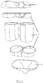
- the figure 6 presents an embodiment of the invention wherein the reservoir is assembled from four constituent elements namely the cover 5, the base 6 and the two compartments 7.
- the end of the compartments has a particular geometry in the form of a rim 8 such that already mentioned that allows to assemble end to end by welding the two compartments.
- the figure 7 presents another embodiment of the invention in which the reservoir is assembled from three constituent elements.
- the assembly is composed of the lid 5 and two shells each including half of the base 6 and the main body 4.
- the two shells can also integrate the lid (at a rate of one half of it per shell ), the assembly is then made from two constituent elements (not shown).
- the assembly is carried out at from six constituent elements.
- the assembly is composed of the cover 5, the base 6 and four pieces of compartments 7 as shown in FIGS. figures 8 and 9 .
- the reservoir can be made from any number of constituent elements and that the object of the invention is to shape / cut the constituent elements made of sheet metal so that they can be assembled by butt welding.
- the present invention has been illustrated for a turbomachine tank but it extends to any application where a tank must be placed in a confined space potentially subjected to vibrations.
- the design of the components makes it possible to make a tank entirely from shaped / cut sheets.
- the removal of castings thus reduces the manufacturing difficulties and the mass related to the foundry.
- the tanks according to the invention comprising substantially cylindrical or ovoid shaped compartments offer better strength than flat tanks according to the state of the art. As a result, the thicknesses of the walls and therefore the total mass can be reduced and for equivalent strength. In this respect, the realization of the tank from steel sheets makes it possible to achieve very small thicknesses without a significant increase in cost compared with parts obtained by foundry which have much higher manufacturing tolerances. It will also be noted that the tank according to the invention no longer requires the use of tie rods or baffles.
- the assembly of the constituent elements of the tank with butt welds has many advantages over joints with fillet welds.
- butt welding is easier to perform.
- the butt welds are 100% controllable by non-destructive controls, which is not the case of welds angles. Indeed, the latter have discontinuities of matter. Therefore, during a non-destructive test, it can not be detected if the detected defect comes from welding or assembly.
- Better assembly and control of butt welds leads to a decrease in defects and scrap rate.
- end-to-end welds are stronger than fillet welds and eliminate the risk of crack propagation at the weld's root.
- the tank according to the invention is particularly suitable for a confined space subjected to vibrations such as in an aircraft engine.
Landscapes
- Engineering & Computer Science (AREA)
- Mechanical Engineering (AREA)
- General Engineering & Computer Science (AREA)
- Butt Welding And Welding Of Specific Article (AREA)
- Structures Of Non-Positive Displacement Pumps (AREA)
- Cylinder Crankcases Of Internal Combustion Engines (AREA)
- Powder Metallurgy (AREA)
Claims (13)
- Verfahren zur Herstellung eines Behälters (1), umfassend einen Hauptkörper (4), eine Basis (6), die den unteren Teil des Hauptkörpers (4) abschließt, und einen Deckel (5), der den oberen Teil des Hauptkörpers (4) abschließt, wobei das Verfahren die folgenden Schritte umfasst:- Formen von Blechen zur Herstellung von Bestandteilen des Behälters (1);- Montieren von jedem der Bestandteile mittels Stumpfschweißen zur Herstellung des Behälters (1),wobei das Verfahren dadurch gekennzeichnet ist, dass der Hauptkörper (4) mit mehreren Kompartimenten (7) versehen ist und dass jedes Kompartiment (7), an jedem seiner Enden, mindestens einen Flansch (8) umfasst, der eine Ende-an-Ende-Montage zwischen den Kompartimenten (7) gestattet.
- Verfahren nach Anspruch 1, wobei die Montage ausschließlich durch Stumpfschweißen jedes der Bestandteile erzielt wird, um den Behälter (1) herzustellen.
- Verfahren nach Anspruch 1 oder 2, wobei der Behälter (1) durch die Montage von zwei oder mehr Bestandteilen gebildet wird.
- Verfahren nach einem der Ansprüche 1 bis 3, wobei die Bestandteile jeweils den Deckel (5), jedes der Kompartimente (7) und die Basis (6) umfassen.
- Verfahren nach einem der Ansprüche 1 bis 3, wobei die Bestandteile jeweils den Deckel (5) und zwei Halbschalen, die jede eine Hälfte der Basis (6) und eine Hälfte des Hauptkörpers (4) beinhalten, umfassen.
- Verfahren nach einem der Ansprüche 1 bis 3, wobei die Bestandteile jeweils zwei Halbschalen umfassen, die jede eine Hälfte des Deckels (5), eine Hälfte der Basis (6) und eine Hälfte des Hauptkörpers (4) beinhalten.
- Verfahren nach einem der Ansprüche 1 bis 3, wobei die Bestandteile jeweils die Basis (6), den Deckel (5) und eine Vielzahl von Stücken des Hauptkörpers (4) umfassen.
- Fluidbehälter (1) für eine Turbomaschine, erhalten durch das Verfahren nach einem der Ansprüche 1 bis 7, welcher Behälter (1) einen Hauptkörper (4), eine Basis (6), die den unteren Teil des Hauptkörpers (4) abschließt, und einen Deckel (5), der den oberen Teil des Hauptkörpers (4) abschließt, umfasst, wobei der Hauptkörper (4), die Basis (6) und der Deckel (5) im Wesentlichen aus Blechen hergestellt sind,
wobei der Behälter dadurch gekennzeichnet ist, dass der Hauptkörper (4) mit mehreren Kompartimenten (7) versehen ist und jedes Kompartiment (7), an jedem seiner Enden, mindestens einen Flansch (8) umfasst, der eine Ende-an-Ende-Montage zwischen den Kompartimenten (7) gestattet. - Behälter (1) nach Anspruch 8, wobei der Behälter (1) Stumpfschweißnähte umfasst und frei von jeglichen Kehlnähten ist.
- Behälter (1) nach einem der Ansprüche 8 bis 9, wobei jedes Kompartiment (7) einen Teil mit einer zylindrischen, nahezu zylindrischen oder eiförmigen Form umfasst.
- Behälter (1) nach einem der Ansprüche 8 bis 10, wobei der Querschnitt des Kompartiments (7) entlang der Längsachse des Kompartiments (7) nicht konstant ist.
- Behälter (1) nach einem der Ansprüche 8 bis 11, wobei die Bleche aus Stahl, Edelstahl, Kupfer, Messing, Aluminium oder einer Legierung auf Basis von Aluminium oder Kupfer hergestellt sind.
- Turbomaschine, umfassend einen Fluidbehälter (1) nach einem der Ansprüche 8 bis 12.
Priority Applications (5)
| Application Number | Priority Date | Filing Date | Title |
|---|---|---|---|
| EP13169374.9A EP2808595B1 (de) | 2013-05-27 | 2013-05-27 | Behälter und sein Herstellungsverfahren |
| CA2852349A CA2852349A1 (en) | 2013-05-27 | 2014-05-20 | Tank and method for manufacturing same |
| RU2014120512A RU2614326C2 (ru) | 2013-05-27 | 2014-05-21 | Резервуар и способ его производства |
| US14/285,071 US9963997B2 (en) | 2013-05-27 | 2014-05-22 | Tank and method for manufacturing same |
| CN201410265528.1A CN104176263B (zh) | 2013-05-27 | 2014-05-27 | 箱体及其制造方法 |
Applications Claiming Priority (1)
| Application Number | Priority Date | Filing Date | Title |
|---|---|---|---|
| EP13169374.9A EP2808595B1 (de) | 2013-05-27 | 2013-05-27 | Behälter und sein Herstellungsverfahren |
Publications (2)
| Publication Number | Publication Date |
|---|---|
| EP2808595A1 EP2808595A1 (de) | 2014-12-03 |
| EP2808595B1 true EP2808595B1 (de) | 2018-11-21 |
Family
ID=48534213
Family Applications (1)
| Application Number | Title | Priority Date | Filing Date |
|---|---|---|---|
| EP13169374.9A Active EP2808595B1 (de) | 2013-05-27 | 2013-05-27 | Behälter und sein Herstellungsverfahren |
Country Status (5)
| Country | Link |
|---|---|
| US (1) | US9963997B2 (de) |
| EP (1) | EP2808595B1 (de) |
| CN (1) | CN104176263B (de) |
| CA (1) | CA2852349A1 (de) |
| RU (1) | RU2614326C2 (de) |
Families Citing this family (8)
| Publication number | Priority date | Publication date | Assignee | Title |
|---|---|---|---|---|
| CN105729050A (zh) * | 2014-12-08 | 2016-07-06 | 上海德朗汽车零部件制造有限公司 | 一种全铝燃油箱的制作方法 |
| FR3051831B1 (fr) * | 2016-05-26 | 2018-05-18 | Safran Aircraft Engines | Carter d'echappement de turbomachine et son procede de fabrication |
| BE1024491B1 (fr) * | 2016-08-11 | 2018-03-12 | Safran Aero Boosters S.A. | Reservoir d'huile de turbomachine avec mesure de niveau |
| BE1024639B1 (fr) * | 2016-10-13 | 2018-05-16 | Safran Aero Boosters S.A. | Reservoir d'huile de turbomachine |
| BE1024640B1 (fr) * | 2016-10-13 | 2018-05-16 | Safran Aero Boosters S.A. | Procede de fabrication additive de reservoir d'huile de turbomachine |
| KR102934977B1 (ko) * | 2021-05-27 | 2026-03-09 | 현대자동차주식회사 | Lpg 저장용 저상형 플랫 봄베 및 이의 제조 방법 |
| CN113246718B (zh) * | 2021-06-30 | 2022-03-11 | 统亚(山东)汽车科技集团有限公司 | 一种尿素箱和油箱总成 |
| US12158104B2 (en) * | 2022-09-30 | 2024-12-03 | General Electric Company | Conformal structure for a gas turbine engine |
Family Cites Families (12)
| Publication number | Priority date | Publication date | Assignee | Title |
|---|---|---|---|---|
| US1858638A (en) * | 1928-04-18 | 1932-05-17 | Russell L Meredith | Dual lubricating system for airplane engines |
| US2038420A (en) * | 1933-09-28 | 1936-04-21 | Pressed Steel Tank Company | Beer barrel and method of making the same |
| US2742873A (en) * | 1951-05-19 | 1956-04-24 | Williston Seamless Can Co Inc | Apparatus for reforming seamless metal containers |
| DE4100725C2 (de) * | 1991-01-10 | 1994-01-05 | Vogel Willi Ag | Zentralschmieraggregat |
| EP0527564B1 (de) * | 1991-07-29 | 1996-05-29 | ROLLS-ROYCE plc | Druckgasbehälter |
| US5697511A (en) * | 1996-09-27 | 1997-12-16 | Boeing North American, Inc. | Tank and method of fabrication |
| WO2005015074A1 (en) * | 2003-08-08 | 2005-02-17 | Honda Motor Co., Ltd. | Liner for pressure vessels and process for producing same |
| JP4553566B2 (ja) * | 2003-08-08 | 2010-09-29 | 昭和電工株式会社 | 圧力容器用ライナおよびその製造方法 |
| EP1732498A1 (de) * | 2004-04-08 | 2006-12-20 | IDD-EAL Manufacturing Company Limited | Behälter zur konstitution einer formulierung in flüssiger form |
| EP1808337A1 (de) * | 2006-01-13 | 2007-07-18 | Rieter Technologies AG | Motorraum Abdeckung |
| US8728389B2 (en) * | 2009-09-01 | 2014-05-20 | United Technologies Corporation | Fabrication of L12 aluminum alloy tanks and other vessels by roll forming, spin forming, and friction stir welding |
| FR2957976B1 (fr) * | 2010-03-26 | 2013-04-12 | Snecma | Dispositif d'etancheite pour une enceinte d'huile d'un turboreacteur |
-
2013
- 2013-05-27 EP EP13169374.9A patent/EP2808595B1/de active Active
-
2014
- 2014-05-20 CA CA2852349A patent/CA2852349A1/en not_active Abandoned
- 2014-05-21 RU RU2014120512A patent/RU2614326C2/ru not_active IP Right Cessation
- 2014-05-22 US US14/285,071 patent/US9963997B2/en active Active
- 2014-05-27 CN CN201410265528.1A patent/CN104176263B/zh active Active
Non-Patent Citations (1)
| Title |
|---|
| None * |
Also Published As
| Publication number | Publication date |
|---|---|
| US9963997B2 (en) | 2018-05-08 |
| US20140345247A1 (en) | 2014-11-27 |
| CA2852349A1 (en) | 2014-11-27 |
| CN104176263B (zh) | 2018-04-20 |
| EP2808595A1 (de) | 2014-12-03 |
| CN104176263A (zh) | 2014-12-03 |
| RU2014120512A (ru) | 2015-11-27 |
| RU2614326C2 (ru) | 2017-03-24 |
Similar Documents
| Publication | Publication Date | Title |
|---|---|---|
| EP2808595B1 (de) | Behälter und sein Herstellungsverfahren | |
| EP2142834B1 (de) | Vorrichtung für eine vorgespannte versiegelungsverbindung mit flanschen | |
| EP2553222B1 (de) | Entlüftungsrohr für tl-triebwerk, verfahren zur montage eines derartigen rohrs und mit diesem rohr ausgestattetes tl-triebwerk | |
| EP2254729B1 (de) | Verfahren zur herstellung einer hohlschaufel | |
| EP2212612B1 (de) | Druckflüssigkeitstank und verfahren zur herstellung eines solchen tanks | |
| EP4033193B1 (de) | Wärmetauscher mit einem aus einem gyroiden bestehenden austauschkörper | |
| WO2014170596A2 (fr) | Brasage sans outillage | |
| EP2320429B1 (de) | Verpackung für den Transport und/oder zur Zwischenlagerung radioaktiver Stoffe, die radial geschichtete Strahlenschutzelemente umfasst | |
| WO2017060600A1 (fr) | Procede de fabrication additive comprenant une etape de pressage isostatique a chaud | |
| FR3060701A1 (fr) | Joint filete pour composant tubulaire | |
| EP3982002B1 (de) | Dämpfungsvorrichtung aus zwei materialien für raumfahrzeuge und verfahren zur herstellung dieser dämpfungsvorrichtung | |
| EP3469206B1 (de) | Raketentriebwerkbrennkammer mit rippen mit variabler zusammensetzung | |
| EP3833854B1 (de) | Innengehäuse einer turbomaschine mit verbesserter wärmeisolierung | |
| FR2979472A1 (fr) | Connecteur dispose entre deux ensembles de stockage d'energie | |
| EP3167177B1 (de) | Zylinderkopf, element und flansch eines kolbenmotors | |
| EP4124791B1 (de) | Behälter, insbesondere für einen flüssigwasserstofftank, der mit mindestens einer kuppel versehen ist, die durch eine äussere schweissnaht befestigt ist | |
| FR2957973A1 (fr) | Tube de degazage d'un turboreacteur, procede de montage d'un tel tube et turboreacteur avec un tel tube | |
| FR3068273B1 (fr) | Dispositif et procede d'assemblage de pieces pour nacelle de turboreacteur d'aeronef | |
| EP4028656B1 (de) | Strukturelle und/oder akustische platte mit einem zur innenseite der platte gerichteten u-förmigen dichtungsflansch und verfahren zur herstellung einer solchen platte | |
| EP2115255B1 (de) | System zur befestigung eines scharniers an einem automobiltürblatt | |
| EP1422004A1 (de) | Speiser für die Verwendung beim Giessen | |
| FR3027551A1 (fr) | Procede de fabrication ameliore d’une piece aeronautique notamment de grandes dimensions | |
| EP1416127B1 (de) | Ventil für Brennkraftmaschine mit einer Abschirmung verbunden mit dem Schaft | |
| FR3100466A1 (fr) | Procédé de brasage d’un panneau pour ensemble propulsif à l’aide d’alliages d’apport différents | |
| EP4251857A1 (de) | Gehäuse mit inneren und/oder äusseren versteifungen |
Legal Events
| Date | Code | Title | Description |
|---|---|---|---|
| PUAI | Public reference made under article 153(3) epc to a published international application that has entered the european phase |
Free format text: ORIGINAL CODE: 0009012 |
|
| 17P | Request for examination filed |
Effective date: 20130527 |
|
| AK | Designated contracting states |
Kind code of ref document: A1 Designated state(s): AL AT BE BG CH CY CZ DE DK EE ES FI FR GB GR HR HU IE IS IT LI LT LU LV MC MK MT NL NO PL PT RO RS SE SI SK SM TR |
|
| AX | Request for extension of the european patent |
Extension state: BA ME |
|
| R17P | Request for examination filed (corrected) |
Effective date: 20150529 |
|
| RBV | Designated contracting states (corrected) |
Designated state(s): AL AT BE BG CH CY CZ DE DK EE ES FI FR GB GR HR HU IE IS IT LI LT LU LV MC MK MT NL NO PL PT RO RS SE SI SK SM TR |
|
| RAP1 | Party data changed (applicant data changed or rights of an application transferred) |
Owner name: SAFRAN AERO BOOSTERS SA |
|
| STAA | Information on the status of an ep patent application or granted ep patent |
Free format text: STATUS: EXAMINATION IS IN PROGRESS |
|
| 17Q | First examination report despatched |
Effective date: 20170316 |
|
| RIC1 | Information provided on ipc code assigned before grant |
Ipc: B21D 51/18 20060101ALI20180406BHEP Ipc: B21D 51/10 20060101ALI20180406BHEP Ipc: F16N 19/00 20060101AFI20180406BHEP Ipc: F01D 25/18 20060101ALI20180406BHEP Ipc: B65D 25/00 20060101ALI20180406BHEP |
|
| GRAP | Despatch of communication of intention to grant a patent |
Free format text: ORIGINAL CODE: EPIDOSNIGR1 |
|
| STAA | Information on the status of an ep patent application or granted ep patent |
Free format text: STATUS: GRANT OF PATENT IS INTENDED |
|
| INTG | Intention to grant announced |
Effective date: 20180604 |
|
| GRAS | Grant fee paid |
Free format text: ORIGINAL CODE: EPIDOSNIGR3 |
|
| GRAA | (expected) grant |
Free format text: ORIGINAL CODE: 0009210 |
|
| STAA | Information on the status of an ep patent application or granted ep patent |
Free format text: STATUS: THE PATENT HAS BEEN GRANTED |
|
| AK | Designated contracting states |
Kind code of ref document: B1 Designated state(s): AL AT BE BG CH CY CZ DE DK EE ES FI FR GB GR HR HU IE IS IT LI LT LU LV MC MK MT NL NO PL PT RO RS SE SI SK SM TR |
|
| REG | Reference to a national code |
Ref country code: CH Ref legal event code: EP |
|
| REG | Reference to a national code |
Ref country code: IE Ref legal event code: FG4D Free format text: LANGUAGE OF EP DOCUMENT: FRENCH |
|
| REG | Reference to a national code |
Ref country code: AT Ref legal event code: REF Ref document number: 1067948 Country of ref document: AT Kind code of ref document: T Effective date: 20181215 |
|
| REG | Reference to a national code |
Ref country code: DE Ref legal event code: R096 Ref document number: 602013046995 Country of ref document: DE |
|
| REG | Reference to a national code |
Ref country code: NL Ref legal event code: MP Effective date: 20181121 |
|
| REG | Reference to a national code |
Ref country code: AT Ref legal event code: MK05 Ref document number: 1067948 Country of ref document: AT Kind code of ref document: T Effective date: 20181121 |
|
| PG25 | Lapsed in a contracting state [announced via postgrant information from national office to epo] |
Ref country code: FI Free format text: LAPSE BECAUSE OF FAILURE TO SUBMIT A TRANSLATION OF THE DESCRIPTION OR TO PAY THE FEE WITHIN THE PRESCRIBED TIME-LIMIT Effective date: 20181121 Ref country code: LV Free format text: LAPSE BECAUSE OF FAILURE TO SUBMIT A TRANSLATION OF THE DESCRIPTION OR TO PAY THE FEE WITHIN THE PRESCRIBED TIME-LIMIT Effective date: 20181121 Ref country code: LT Free format text: LAPSE BECAUSE OF FAILURE TO SUBMIT A TRANSLATION OF THE DESCRIPTION OR TO PAY THE FEE WITHIN THE PRESCRIBED TIME-LIMIT Effective date: 20181121 Ref country code: NO Free format text: LAPSE BECAUSE OF FAILURE TO SUBMIT A TRANSLATION OF THE DESCRIPTION OR TO PAY THE FEE WITHIN THE PRESCRIBED TIME-LIMIT Effective date: 20190221 Ref country code: AT Free format text: LAPSE BECAUSE OF FAILURE TO SUBMIT A TRANSLATION OF THE DESCRIPTION OR TO PAY THE FEE WITHIN THE PRESCRIBED TIME-LIMIT Effective date: 20181121 Ref country code: BG Free format text: LAPSE BECAUSE OF FAILURE TO SUBMIT A TRANSLATION OF THE DESCRIPTION OR TO PAY THE FEE WITHIN THE PRESCRIBED TIME-LIMIT Effective date: 20190221 Ref country code: HR Free format text: LAPSE BECAUSE OF FAILURE TO SUBMIT A TRANSLATION OF THE DESCRIPTION OR TO PAY THE FEE WITHIN THE PRESCRIBED TIME-LIMIT Effective date: 20181121 Ref country code: ES Free format text: LAPSE BECAUSE OF FAILURE TO SUBMIT A TRANSLATION OF THE DESCRIPTION OR TO PAY THE FEE WITHIN THE PRESCRIBED TIME-LIMIT Effective date: 20181121 Ref country code: IS Free format text: LAPSE BECAUSE OF FAILURE TO SUBMIT A TRANSLATION OF THE DESCRIPTION OR TO PAY THE FEE WITHIN THE PRESCRIBED TIME-LIMIT Effective date: 20190321 |
|
| PG25 | Lapsed in a contracting state [announced via postgrant information from national office to epo] |
Ref country code: NL Free format text: LAPSE BECAUSE OF FAILURE TO SUBMIT A TRANSLATION OF THE DESCRIPTION OR TO PAY THE FEE WITHIN THE PRESCRIBED TIME-LIMIT Effective date: 20181121 Ref country code: PT Free format text: LAPSE BECAUSE OF FAILURE TO SUBMIT A TRANSLATION OF THE DESCRIPTION OR TO PAY THE FEE WITHIN THE PRESCRIBED TIME-LIMIT Effective date: 20190321 Ref country code: RS Free format text: LAPSE BECAUSE OF FAILURE TO SUBMIT A TRANSLATION OF THE DESCRIPTION OR TO PAY THE FEE WITHIN THE PRESCRIBED TIME-LIMIT Effective date: 20181121 Ref country code: SE Free format text: LAPSE BECAUSE OF FAILURE TO SUBMIT A TRANSLATION OF THE DESCRIPTION OR TO PAY THE FEE WITHIN THE PRESCRIBED TIME-LIMIT Effective date: 20181121 Ref country code: AL Free format text: LAPSE BECAUSE OF FAILURE TO SUBMIT A TRANSLATION OF THE DESCRIPTION OR TO PAY THE FEE WITHIN THE PRESCRIBED TIME-LIMIT Effective date: 20181121 |
|
| PG25 | Lapsed in a contracting state [announced via postgrant information from national office to epo] |
Ref country code: IT Free format text: LAPSE BECAUSE OF FAILURE TO SUBMIT A TRANSLATION OF THE DESCRIPTION OR TO PAY THE FEE WITHIN THE PRESCRIBED TIME-LIMIT Effective date: 20181121 Ref country code: CZ Free format text: LAPSE BECAUSE OF FAILURE TO SUBMIT A TRANSLATION OF THE DESCRIPTION OR TO PAY THE FEE WITHIN THE PRESCRIBED TIME-LIMIT Effective date: 20181121 Ref country code: DK Free format text: LAPSE BECAUSE OF FAILURE TO SUBMIT A TRANSLATION OF THE DESCRIPTION OR TO PAY THE FEE WITHIN THE PRESCRIBED TIME-LIMIT Effective date: 20181121 Ref country code: PL Free format text: LAPSE BECAUSE OF FAILURE TO SUBMIT A TRANSLATION OF THE DESCRIPTION OR TO PAY THE FEE WITHIN THE PRESCRIBED TIME-LIMIT Effective date: 20181121 |
|
| REG | Reference to a national code |
Ref country code: DE Ref legal event code: R097 Ref document number: 602013046995 Country of ref document: DE |
|
| PG25 | Lapsed in a contracting state [announced via postgrant information from national office to epo] |
Ref country code: SM Free format text: LAPSE BECAUSE OF FAILURE TO SUBMIT A TRANSLATION OF THE DESCRIPTION OR TO PAY THE FEE WITHIN THE PRESCRIBED TIME-LIMIT Effective date: 20181121 Ref country code: EE Free format text: LAPSE BECAUSE OF FAILURE TO SUBMIT A TRANSLATION OF THE DESCRIPTION OR TO PAY THE FEE WITHIN THE PRESCRIBED TIME-LIMIT Effective date: 20181121 Ref country code: SK Free format text: LAPSE BECAUSE OF FAILURE TO SUBMIT A TRANSLATION OF THE DESCRIPTION OR TO PAY THE FEE WITHIN THE PRESCRIBED TIME-LIMIT Effective date: 20181121 Ref country code: RO Free format text: LAPSE BECAUSE OF FAILURE TO SUBMIT A TRANSLATION OF THE DESCRIPTION OR TO PAY THE FEE WITHIN THE PRESCRIBED TIME-LIMIT Effective date: 20181121 |
|
| PLBE | No opposition filed within time limit |
Free format text: ORIGINAL CODE: 0009261 |
|
| STAA | Information on the status of an ep patent application or granted ep patent |
Free format text: STATUS: NO OPPOSITION FILED WITHIN TIME LIMIT |
|
| 26N | No opposition filed |
Effective date: 20190822 |
|
| PG25 | Lapsed in a contracting state [announced via postgrant information from national office to epo] |
Ref country code: SI Free format text: LAPSE BECAUSE OF FAILURE TO SUBMIT A TRANSLATION OF THE DESCRIPTION OR TO PAY THE FEE WITHIN THE PRESCRIBED TIME-LIMIT Effective date: 20181121 |
|
| REG | Reference to a national code |
Ref country code: CH Ref legal event code: PL |
|
| PG25 | Lapsed in a contracting state [announced via postgrant information from national office to epo] |
Ref country code: CH Free format text: LAPSE BECAUSE OF NON-PAYMENT OF DUE FEES Effective date: 20190531 Ref country code: LI Free format text: LAPSE BECAUSE OF NON-PAYMENT OF DUE FEES Effective date: 20190531 Ref country code: MC Free format text: LAPSE BECAUSE OF FAILURE TO SUBMIT A TRANSLATION OF THE DESCRIPTION OR TO PAY THE FEE WITHIN THE PRESCRIBED TIME-LIMIT Effective date: 20181121 |
|
| PG25 | Lapsed in a contracting state [announced via postgrant information from national office to epo] |
Ref country code: LU Free format text: LAPSE BECAUSE OF NON-PAYMENT OF DUE FEES Effective date: 20190527 |
|
| PG25 | Lapsed in a contracting state [announced via postgrant information from national office to epo] |
Ref country code: TR Free format text: LAPSE BECAUSE OF FAILURE TO SUBMIT A TRANSLATION OF THE DESCRIPTION OR TO PAY THE FEE WITHIN THE PRESCRIBED TIME-LIMIT Effective date: 20181121 |
|
| PG25 | Lapsed in a contracting state [announced via postgrant information from national office to epo] |
Ref country code: IE Free format text: LAPSE BECAUSE OF NON-PAYMENT OF DUE FEES Effective date: 20190527 |
|
| PG25 | Lapsed in a contracting state [announced via postgrant information from national office to epo] |
Ref country code: CY Free format text: LAPSE BECAUSE OF FAILURE TO SUBMIT A TRANSLATION OF THE DESCRIPTION OR TO PAY THE FEE WITHIN THE PRESCRIBED TIME-LIMIT Effective date: 20181121 |
|
| PG25 | Lapsed in a contracting state [announced via postgrant information from national office to epo] |
Ref country code: GR Free format text: LAPSE BECAUSE OF FAILURE TO SUBMIT A TRANSLATION OF THE DESCRIPTION OR TO PAY THE FEE WITHIN THE PRESCRIBED TIME-LIMIT Effective date: 20181121 |
|
| PG25 | Lapsed in a contracting state [announced via postgrant information from national office to epo] |
Ref country code: MT Free format text: LAPSE BECAUSE OF FAILURE TO SUBMIT A TRANSLATION OF THE DESCRIPTION OR TO PAY THE FEE WITHIN THE PRESCRIBED TIME-LIMIT Effective date: 20181121 Ref country code: HU Free format text: LAPSE BECAUSE OF FAILURE TO SUBMIT A TRANSLATION OF THE DESCRIPTION OR TO PAY THE FEE WITHIN THE PRESCRIBED TIME-LIMIT; INVALID AB INITIO Effective date: 20130527 |
|
| PG25 | Lapsed in a contracting state [announced via postgrant information from national office to epo] |
Ref country code: MK Free format text: LAPSE BECAUSE OF FAILURE TO SUBMIT A TRANSLATION OF THE DESCRIPTION OR TO PAY THE FEE WITHIN THE PRESCRIBED TIME-LIMIT Effective date: 20181121 |
|
| PGFP | Annual fee paid to national office [announced via postgrant information from national office to epo] |
Ref country code: DE Payment date: 20250519 Year of fee payment: 13 |
|
| PGFP | Annual fee paid to national office [announced via postgrant information from national office to epo] |
Ref country code: GB Payment date: 20250527 Year of fee payment: 13 |
|
| PGFP | Annual fee paid to national office [announced via postgrant information from national office to epo] |
Ref country code: BE Payment date: 20250523 Year of fee payment: 13 |
|
| PGFP | Annual fee paid to national office [announced via postgrant information from national office to epo] |
Ref country code: FR Payment date: 20250526 Year of fee payment: 13 |