EP4033193B1 - Wärmetauscher mit einem aus einem gyroiden bestehenden austauschkörper - Google Patents
Wärmetauscher mit einem aus einem gyroiden bestehenden austauschkörper Download PDFInfo
- Publication number
- EP4033193B1 EP4033193B1 EP22152808.6A EP22152808A EP4033193B1 EP 4033193 B1 EP4033193 B1 EP 4033193B1 EP 22152808 A EP22152808 A EP 22152808A EP 4033193 B1 EP4033193 B1 EP 4033193B1
- Authority
- EP
- European Patent Office
- Prior art keywords
- heat exchanger
- fluid
- outlet
- inlet
- exchanger
- Prior art date
- Legal status (The legal status is an assumption and is not a legal conclusion. Google has not performed a legal analysis and makes no representation as to the accuracy of the status listed.)
- Active
Links
Images





Classifications
-
- F—MECHANICAL ENGINEERING; LIGHTING; HEATING; WEAPONS; BLASTING
- F28—HEAT EXCHANGE IN GENERAL
- F28F—DETAILS OF HEAT-EXCHANGE AND HEAT-TRANSFER APPARATUS, OF GENERAL APPLICATION
- F28F7/00—Elements not covered by group F28F1/00, F28F3/00 or F28F5/00
- F28F7/02—Blocks traversed by passages for heat-exchange media
-
- B—PERFORMING OPERATIONS; TRANSPORTING
- B33—ADDITIVE MANUFACTURING TECHNOLOGY
- B33Y—ADDITIVE MANUFACTURING, i.e. MANUFACTURING OF THREE-DIMENSIONAL [3D] OBJECTS BY ADDITIVE DEPOSITION, ADDITIVE AGGLOMERATION OR ADDITIVE LAYERING, e.g. BY 3D PRINTING, STEREOLITHOGRAPHY OR SELECTIVE LASER SINTERING
- B33Y80/00—Products made by additive manufacturing
-
- F—MECHANICAL ENGINEERING; LIGHTING; HEATING; WEAPONS; BLASTING
- F28—HEAT EXCHANGE IN GENERAL
- F28F—DETAILS OF HEAT-EXCHANGE AND HEAT-TRANSFER APPARATUS, OF GENERAL APPLICATION
- F28F13/00—Arrangements for modifying heat-transfer, e.g. increasing, decreasing
- F28F13/06—Arrangements for modifying heat-transfer, e.g. increasing, decreasing by affecting the pattern of flow of the heat-exchange media
- F28F13/08—Arrangements for modifying heat-transfer, e.g. increasing, decreasing by affecting the pattern of flow of the heat-exchange media by varying the cross-section of the flow channels
-
- F—MECHANICAL ENGINEERING; LIGHTING; HEATING; WEAPONS; BLASTING
- F28—HEAT EXCHANGE IN GENERAL
- F28F—DETAILS OF HEAT-EXCHANGE AND HEAT-TRANSFER APPARATUS, OF GENERAL APPLICATION
- F28F9/00—Casings; Header boxes; Auxiliary supports for elements; Auxiliary members within casings
- F28F9/02—Header boxes; End plates
-
- F—MECHANICAL ENGINEERING; LIGHTING; HEATING; WEAPONS; BLASTING
- F28—HEAT EXCHANGE IN GENERAL
- F28F—DETAILS OF HEAT-EXCHANGE AND HEAT-TRANSFER APPARATUS, OF GENERAL APPLICATION
- F28F2210/00—Heat exchange conduits
- F28F2210/02—Heat exchange conduits with particular branching, e.g. fractal conduit arrangements
-
- F—MECHANICAL ENGINEERING; LIGHTING; HEATING; WEAPONS; BLASTING
- F28—HEAT EXCHANGE IN GENERAL
- F28F—DETAILS OF HEAT-EXCHANGE AND HEAT-TRANSFER APPARATUS, OF GENERAL APPLICATION
- F28F2250/00—Arrangements for modifying the flow of the heat exchange media, e.g. flow guiding means; Particular flow patterns
- F28F2250/10—Particular pattern of flow of the heat exchange media
- F28F2250/106—Particular pattern of flow of the heat exchange media with cross flow
-
- F—MECHANICAL ENGINEERING; LIGHTING; HEATING; WEAPONS; BLASTING
- F28—HEAT EXCHANGE IN GENERAL
- F28F—DETAILS OF HEAT-EXCHANGE AND HEAT-TRANSFER APPARATUS, OF GENERAL APPLICATION
- F28F2255/00—Heat exchanger elements made of materials having special features or resulting from particular manufacturing processes
Definitions
- the invention relates to a heat exchanger and an associated heat exchanger assembly.
- the function of heat exchangers is to implement a heat exchange between several fluids without mixing them.
- Heat exchangers may comprise an internal part comprising a body forming two separate fluid circulation circuits, and an external part comprising a frame and collectors fixed to the frame. These collectors are connected on the one hand to conduits for bringing the fluids to the internal part of the exchanger and on the other hand to conduits for evacuating the fluids from the internal part of the exchanger once they have circulated in the exchanger.
- a hot fluid and a cold fluid circulate respectively in the two separate circulation circuits formed by the body. During their circulation, a heat transfer occurs from the hot fluid to the cold fluid, through the body.
- the document US 2020/033070 A1 relates to a heat exchanger comprising two inlets and two outlets as well as a minimal surface structure which separates two volumes in the body of the exchanger, the two volumes communicating respectively with the first inlet and outlet and with the second inlet and outlet.
- one of the two fluids may undergo a change of state while circulating in the exchanger.
- the cold fluid may be in the liquid state when it enters the body of the exchanger and in As it heats up, the cold fluid can partially or completely vaporize.
- the hot fluid can be in a gaseous state when it enters the exchanger and as it cools, the hot fluid can partially or completely liquefy.
- One aim of the invention is to propose a heat exchanger having a large exchange surface between the two fluids while being compact.
- Another aim of the invention is to propose a heat exchanger which is suitable for the treatment of fluids likely to undergo a total or partial change of state during their circulation in the exchanger.
- the invention proposes a heat exchanger comprising an exchanger body delimited by a first inlet surface, a first outlet surface, a second inlet surface and a second outlet surface, in which the exchanger body comprises a gyroid-shaped separating wall separating a first network of channels for the circulation of a first fluid from the first inlet surface to the first outlet surface, and a second network of channels for the circulation of a second fluid from the second inlet surface to the second outlet surface.
- first channel network comprises first channels having a cross-section that varies by continuously increasing from the first inlet surface to the first outlet surface
- the second channel network comprises second channels having a cross-section that varies by continuously decreasing from the second inlet surface to the second outlet surface
- the gyroid shape of the separating wall allows for maximizing heat exchange between the first fluid circulating in the first network of channels and the second fluid circulating in the second network of channels, while occupying minimal volume.
- the curved shape of the channels helps to limit pressure losses in the fluid flows circulating inside the exchanger body.
- the section of the channels has a circular shape, which allows the exchanger body to withstand high pressure of the fluids circulating in the exchanger body.
- the progressive variation of the section of the first channels from the first inlet surface to the first outlet surface, and the progressive variation of the section of the second channels from the first inlet surface to the first outlet surface allows the first fluid to expand during its circulation through the exchanger body, and the second fluid to contract during its circulation through the exchanger body. This avoids generating excessively large variations in the speed of the fluids and/or the pressure of the fluids inside the exchanger.
- the body of the heat exchanger may be designed so as to allow a total or partial change of state of the first fluid during its circulation in the heat exchanger.
- the invention further relates to a heat exchanger assembly comprising a plurality of heat exchangers as defined above, including a first heat exchanger and a second heat exchanger, wherein the first outlet surface of the first heat exchanger is connected to the first inlet surface of the second heat exchanger such that the first fluid flows successively through the first heat exchanger and through the second heat exchanger, and wherein the second outlet surface of the second heat exchanger is connected to the second inlet surface of the first heat exchanger such that the second fluid flows successively through the second heat exchanger and through the first heat exchanger.
- the heat exchanger 1 shown comprises an exchanger body 2 and collectors 3 to 6.
- the exchanger body 2 is delimited by a rectangular parallelepiped (illustrated in dotted lines), for example a cube, having six faces (or flat surfaces).
- the faces include a first face 7, a second face 8, a third face 9, a fourth face 10, a fifth face 11 and a sixth face 12.
- the first face 7 constitutes a first entry surface.
- the second face 8 constitutes a first output surface, opposite the first input surface.
- the third face 9 constitutes a second input surface.
- the fourth face 10 constitutes a second output surface, opposite the second input surface.
- the exchanger body 2 comprises a gyroid-shaped separating wall 21.
- F is a function such that for x and y fixed, F is strictly monotone, and a, b and c are non-zero coefficients, and K is a constant.
- each of the coefficients a, b and c is equal to 1.
- F is considered strictly monotonic, if for all z 1 ⁇ z 2 , F (z 1 ) ⁇ F(z 2 ), or for all z 1 ⁇ z 2 , F (z 1 ) > F(z 2 ), in the volume occupied by the exchanger body.
- the separating wall 21 separates a first network of channels 22 for the circulation of a first fluid, and a second network of channels 23 for the circulation of a second fluid.
- the first network of channels 22 and the second network of channels 23 are nested within each other. All the channels of the first network of channels 22 communicate with each other. All the channels of the second network of channels 23 communicate with each other. But the channels of the first network of channels 22 do not communicate with the channels of the second network of channels 23, so that the fluids circulating in the two networks do not mix.
- the function F can be a linear function of x, y and/or z.
- the exchanger body 2 further comprises a first inlet wall 71, a first outlet wall 81, a second inlet wall 91, a second outlet wall 101, a first closing wall 111 and a second closing wall 121.
- the first inlet wall 71 and the first outlet wall 81 close the channels of the second network of channels opening onto the first inlet surface 7 and onto the first outlet surface 8.
- the first inlet wall 71 has a first series of inlet openings 72 arranged so as to allow circulation of the first fluid through the first inlet surface 7.
- the first inlet wall 71 allows penetration of the first fluid through the first inlet surface 7 into the first network of channels 22 while preventing penetration of the first fluid through the first inlet surface 7 into the second network of channels 23.
- the first outlet wall 81 has a first series of outlet openings 82 arranged so as to allow circulation of the first fluid through the first outlet surface 8.
- the first outlet wall 81 allows extraction of the first fluid through the first outlet surface 8 out of the first network of channels 22, while preventing extraction of the second fluid through the first outlet surface 8 out of the second network of channels 23.
- the first fluid enters the interior of the exchanger body 2 via the first inlet wall 71, circulates in the channels of the first network of channels 22, and leaves the exchanger body 2 via the first outlet wall 81.
- the second inlet wall 91 and the second outlet wall 101 close the channels of the first network of channels 22 opening onto the second inlet surface 9 and onto the second outlet surface 10.
- the second inlet wall 91 has a second series of inlet openings 92 arranged so as to allow circulation of the second fluid through the second inlet surface 9.
- the second inlet wall 91 allows penetration of the second fluid through the second inlet surface 9 into the second network of channels 23, while preventing penetration of the second fluid through the second inlet surface 9 into the first network of channels 22.
- the second outlet wall 101 has a second series of outlet openings 102 arranged so as to allow circulation of the second fluid through the second outlet surface 10.
- the second outlet wall 101 allows extraction of the second fluid through the second outlet surface 10 out of the second network of channels 23, while preventing extraction of the first fluid through the second outlet surface 10 out of the first network of channels 22.
- the second fluid enters the interior of the exchanger body 2 via the second inlet wall 9, circulates in the channels of the second network of channels 23, and leaves the exchanger body 2 via the second outlet wall 10.
- the first closing wall 11 and the second closing wall 12 close both the channels of the first network of channels 22 and the channels of the second network of channels 23 opening onto the fifth face 11 and the sixth face 12 of the parallelepiped.
- the exchanger body 2 (including the separating wall 21 and the walls 71, 81, 91, 101, 111 and 121) may be formed from a single piece of material, by an additive manufacturing technique or by a casting technique.
- the additive manufacturing technique may be a powder bed additive manufacturing technique (for example a selective laser melting technique - called SLM or "Selective Laser Melting” in English), or a powder or wire deposition additive manufacturing technique (for example a concentrated energy deposition technique - called DED or "Directed Energy Deposition” in English), or a wire and laser additive manufacturing technique (called WLAM or "Wire and Laser Additive Manufacturing").
- the material of the exchanger body 2 is a material having good thermal conductivity, i.e. a thermal conductivity typically between 20 and 400 W/mK (watts per meter-kelvin).
- the material is preferably a metal, for example titanium, or a metal alloy, for example a carbon steel (i.e. a steel whose main alloying component is carbon with a content of between 0.12 and 2.0%, the other alloying elements being in very small quantities) or a stainless steel (i.e. a steel comprising less than 1.2% carbon with more than 10.5% chromium) or an austenitic steel (i.e.
- a steel characterized by a face-centered cubic molecular structure such as for example a stainless steel obtained with 18% chromium and 8% nickel), or a duplex steel (i.e. a stainless steel having a two-phase structure composed of ferrite supplemented with 40 to 60% austenite, and typically containing at least 20% chromium, nickel, molybdenum, nitrogen and optionally copper and/or tungsten) or a super duplex steel (typically containing between 25% and 30% chromium, between 6 and 8% nickel, molybdenum, nitrogen and optionally copper and/or tungsten) or an alloy based on nickel, aluminum or titanium.
- the material of the exchanger body 2 may be a polymer, a mixture of polymers or a composite material (for example a filled polymer).
- Manifolds 3 to 6 include a first inlet manifold 3, a first outlet manifold 4, a second inlet manifold 5, and a second outlet manifold 6.
- the first inlet manifold 3 and the first outlet manifold 4 are suitable for guiding the first fluid (for example a cold fluid) so that the first fluid circulates inside the exchanger body 2 in the first network of channels 22.
- first fluid for example a cold fluid
- the first inlet manifold 3 is fixed to the first inlet surface 7 of the exchanger body 2.
- the first inlet manifold 3 comprises a wall 31 and a first inlet pipe 32 suitable for being connected to a first conduit for supplying the first fluid.
- the first outlet collector 4 is fixed to the first outlet surface 8 of the exchanger body 2.
- the first outlet collector 4 comprises a wall 41 and a first outlet pipe 42 suitable for being connected to a first conduit for extracting the first fluid.
- the second inlet manifold 5 and the second outlet manifold 6 are suitable for guiding the second fluid (for example a hot fluid) so that the second fluid circulates inside the exchanger body 2 in the second network of channels 23.
- the second fluid for example a hot fluid
- the second inlet manifold 5 is fixed on the second inlet surface 9 of the exchanger body 2.
- the second inlet manifold 5 comprises a wall 51 and a second inlet pipe 52 suitable for being connected to a second conduit for supplying the second fluid.
- the second outlet collector 6 is fixed to the second outlet surface 10 of the exchanger body 2.
- the second outlet collector 6 comprises a wall 61 and a second outlet pipe 62 suitable for being connected to a second conduit for extracting the second fluid.
- the first fluid (arrow A) is injected into the heat exchanger 1 via the first inlet pipe 32 of the first inlet manifold 3.
- the first fluid enters the exchanger body 2 by passing through the first fluid inlet wall 71 in the first network of channels 22.
- the first fluid circulates in the first network of channels 22 and leaves the exchanger body 2 by passing through the first fluid outlet wall 81.
- the first fluid is extracted from the exchanger via the first outlet pipe 42 of the first outlet manifold 4.
- the second fluid (arrow B) is injected into the heat exchanger 1 via the second inlet pipe 52 of the second inlet manifold 5.
- the second fluid enters the exchanger body 2 by passing through the second fluid inlet wall 91 in the second network of channels 23.
- the second fluid circulates in the second network of channels 23 and leaves the exchanger body 2 by passing through the second fluid outlet wall 101.
- the second fluid is extracted from the exchanger via the second outlet pipe 62 of the second outlet manifold 6.
- the gyroid shape of the separating wall 21 makes it possible to maximize the exchange surface between the two fluids, while limiting pressure losses.
- coefficients A and B are zero and coefficient C is non-zero.
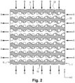
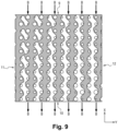
- the first network of channels 22 comprises first channels having a cross-section (section parallel to the XY plane) which varies continuously from the first inlet surface 7 to the first outlet surface 8.
- the cross-section of the first channels varies along the Z axis (axis parallel to the direction of circulation of the first fluid in the heat exchanger 1).
- each of the first channels has a cross-section which increases continuously from the first inlet surface 7 to the first outlet surface 8.
- first set of outlet openings 82 occupies an area in the first outlet wall 81 that is greater than the area occupied by the first set of inlet openings 72 in the first inlet wall 71.
- the geometry of the first channels allows an expansion of the first fluid during its circulation in the body 2 of the heat exchanger 1, without increasing too significantly the speed of the first fluid in the exchanger and without increasing too significantly the pressure of the first fluid.
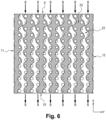
- the second network of channels 23 comprises second channels having a constant cross-section (section parallel to the YZ plane) from the second inlet surface 9 to the second outlet surface 10.
- the cross-section of the second channels is constant along the X axis (circulation axis of the second fluid).
- the second set of outlet openings 102 in the second outlet wall 101 has an area identical to the area of the second set of inlet openings 92 in the second inlet wall 91.
- each of the first channels and the second channels has a constant cross-section from the fifth surface 11 to the sixth surface 12.
- coefficient B is zero and coefficients A and C are non-zero.
- A C.
- F is a function such that for x and y fixed, F is strictly monotone, and for z and y fixed, F is strictly monotone.
- each of the first channels has a cross-section which increases continuously from the first inlet surface 7 to the first outlet surface 8.
- first set of outlet openings 82 occupies an area in the first outlet wall 81 that is greater than the area occupied by the first set of inlet openings 72 in the first inlet wall 71.
- the geometry of the first channels allows an expansion of the first fluid during its circulation in the body 2 of the heat exchanger 1, without increasing too significantly the speed of the first fluid in the exchanger and without increasing too significantly the pressure in the first fluid.
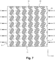
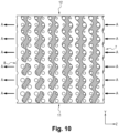
- the second network of channels 23 comprises second channels having a cross-section (section parallel to the YZ plane) which varies continuously from the second inlet surface 9 to the second outlet surface 10.
- the cross-section of the second channels varies along the X axis (axis parallel to the direction of circulation of the second fluid in the heat exchanger 1).
- each of the second channels has a cross-section which decreases from the second inlet surface 9 to the second outlet surface 10.
- the second set of outlet openings 102 occupies an area in the second outlet wall 101 that is less than the area occupied by the second set of inlet openings 92 in the second inlet wall 91.
- the geometry of the second channels allows a contraction of the second fluid during its circulation in the body 2 of the heat exchanger 1, without reducing too significantly the speed of the second fluid in the exchanger and without reducing too significantly the pressure in the second fluid.
- each of the first channels and the second channels has a constant cross-section (section parallel to the XZ plane) from the fifth surface 11 to the sixth surface 12.
- the coefficients A, B and C are non-zero.
- F is a function such that for x and y fixed, F is strictly monotone, for z and y fixed, F is strictly monotone and for x and z fixed, F is strictly monotone.
- the first network of channels 22 comprises first channels having a cross-section (section parallel to the XY plane) which varies continuously from the first inlet surface 7 to the first outlet surface 8.
- the cross-section of the first channels varies along the Z axis (axis parallel to the direction of circulation of the first fluid in the heat exchanger 1).
- each of the first channels has a continuously increasing cross-section from the first inlet surface 7 to the first outlet surface 8.
- first set of outlet openings 82 occupies an area in the first outlet wall 81 that is greater than the area occupied by the first set of inlet openings 72 in the first inlet wall 71.
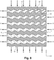
- the second network of channels 23 also comprises second channels having a cross-section (section parallel to the YZ plane) which varies continuously from the second inlet surface 9 to the second outlet surface 10.
- the cross-section of the second channels varies along the X axis (axis parallel to the direction of circulation of the second fluid in the heat exchanger 1).
- each of the second channels has a cross-section which decreases continuously from the second inlet surface 9 to the second outlet surface 10.
- the second set of outlet openings 102 occupies an area in the second outlet wall 101 that is less than the area occupied by the second set of inlet openings 92 in the second inlet wall 91.
- each of the first channels and the second channels also has a cross-section (section parallel to the XZ plane) which varies continuously from the fifth surface 11 to the sixth surface 12.
- the exchanger assembly 13 illustrated on the Figure 11 comprises a plurality of heat exchangers 1A, 1B and 1C stacked on top of each other. Each heat exchanger 1A, 1B and 1C is in accordance with the heat exchanger 1 of the Figure 1 .
- the exchanger assembly 13 comprises a first heat exchanger 1A, a second heat exchanger 1B and a third heat exchanger 1C.
- the first outlet surface of the first heat exchanger 1A is connected to the first inlet surface of the second heat exchanger 1B and the first outlet surface of the second heat exchanger 1B is connected to the first inlet surface of the third heat exchanger 1C so that the first fluid (arrow A) circulates successively through the first heat exchanger 1A, the second heat exchanger 1B and the third heat exchanger 1C.
- the second outlet surface of the third heat exchanger 1C is connected to the second inlet surface of the second heat exchanger 1B and the second outlet surface of the second heat exchanger 1B is connected to the second inlet surface of the first heat exchanger 1A so that the second fluid successively circulates through the third heat exchanger 1C, the second heat exchanger 1B and the first heat exchanger 1A.
- conduits 18 Each conduit 18 has one end connected to the second outlet pipe 52 of the exchanger and another end connected to the second inlet pipe 62 of the following exchanger in the stack.
- the exchanger assembly may be designed such that in each heat exchanger 1A to 1C, the first channel network 22 comprises first channels having a cross-section that continuously increases along the circulation path of the first fluid.
- each heat exchanger may comprise an exchanger body 2 having first channels having a cross-section greater than a cross-section of the preceding exchanger in the stack, such that the first fluid circulates successively in each exchanger 1A, 1B and 1C, via first channels having a cross-section which increases from one exchanger to the following exchanger.
- the exchanger assembly so that in each heat exchanger 1A to 1C, the second channel network 23 includes second channels having a cross-section that decreases along the flow path of the second fluid.
- each heat exchanger may comprise an exchanger body 2 having second channels having a cross-section smaller than a cross-section of the previous exchanger in the stack, so that the second fluid circulates successively in each exchanger 1C, 1B and 1A, via second channels having a cross-section which decreases continuously from one exchanger to the following exchanger.
- FIG. 12 schematically represents a variant of the exchanger assembly 13 of the Figure 11 .
- the exchanger assembly 13 comprises a first heat exchanger 1A, a second heat exchanger 1B and a third heat exchanger 1C.
- the first outlet surface of the first heat exchanger 1A is connected to the first inlet surface of the second heat exchanger 1B and the first outlet surface of the second heat exchanger 1B is connected to the first inlet surface of the third heat exchanger 1C so that the first fluid (arrow A) circulates successively through the first heat exchanger 1A, the second heat exchanger 1B and the third heat exchanger 1C.
- the second outlet surface of the first heat exchanger 1A is connected to the second inlet surface of the second heat exchanger 1B and the second outlet surface of the second heat exchanger 1B is connected to the second inlet surface of the third heat exchanger 1C so that the second fluid successively circulates through the first heat exchanger 1A, the second heat exchanger 1B and the third heat exchanger 1C.
- each heat exchanger 1A, 1B and 1C further comprises an external casing 16 surrounding the exchanger body 2 and partitions 165, 166, 167 and 168 connecting the external casing 16 to the exchanger body 2.
- the external casing 16 comprises a first wall 162 extending at a distance from and facing the second inlet surface 9 of the exchanger body 2 and a second wall 163 extending at a distance from and facing the second outlet surface 10 of the exchanger body 2.
- Partitions 165, 166, 167 and 168 include a first partition 165 and a second partition 166.
- the partitions 165 and 166 delimit with the first wall 162 and the second inlet surface 9, an inlet space 53 intended to receive the second fluid entering the exchanger body 2.
- the first wall 162 and the partitions 165, 166 form the second inlet manifold 5.
- the partitions 167 and 168 delimit with the second wall 163 and the second outlet surface 10, an outlet space 63 intended to receive the second fluid at the outlet of the exchanger body 2.
- the second wall 163 and the partitions 167 and 168 form the second outlet collector 6.
- the second fluid (arrow B) circulates successively through the first exchanger 1A, the second exchanger 1B then the third exchanger 1C.
- the heat exchangers 1A, 1B and 1C are arranged one after the other in the stack, so that the outlet space 63 of a heat exchanger (for example the heat exchanger 1A) communicates with the inlet space 53 of the following heat exchanger (for example the heat exchanger 1B) in the direction of circulation of the second fluid.
- a heat exchanger for example the heat exchanger 1A
- the inlet space 53 of the following heat exchanger for example the heat exchanger 1B
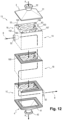
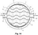
- THE figures 13 And 14 schematically represent a heat exchanger 1 according to a second embodiment of the invention.
- the heat exchanger 1 shown comprises an exchanger body 2, two spacers 14 and 15, a casing 16 and two end plates 3 and 4.
- the exchanger body 2 is delimited by a cylinder of revolution.
- the cylinder of revolution has an axis Z of revolution.
- the cylinder comprises a cylindrical surface 17 and two transverse faces 7 and 8 each extending in a plane orthogonal to the axis Z.
- the first face 7 constitutes a first entry surface.
- the second face 8 constitutes a first output surface, opposite the first input surface.
- the cylindrical surface 17 comprises a surface portion forming a second inlet surface 9 and a surface portion forming a second outlet surface 10, opposite the second inlet surface.
- the exchanger body 2 comprises a gyroid-shaped separating wall 21.
- F is a function such that for x and y fixed, F is strictly monotone, and a, b and c are non-zero coefficients, and K is a constant.
- each of the coefficients a, b and c is equal to 1.
- F is considered strictly monotonic, if for all z 1 ⁇ z 2 , F (z 1 ) ⁇ F(z 2 ), or for all z 1 ⁇ z 2 , F (z 1 ) > F(z 2 ), in the volume occupied by the exchanger body.
- the separating wall 21 separates a first network of channels 22 for the circulation of a first fluid, and a second network of channels 23 for the circulation of a second fluid.
- the first network of channels 22 and the second network of channels 23 are nested within each other. But the fluids circulating in the two networks of channels 22 and 23 do not mix.
- the function F may be a linear function of x, y and/or z.
- the exchanger body 2 further comprises a first inlet wall 71, a first outlet wall 81, a second inlet wall 91 and a second outlet wall 101.
- the first inlet wall 71 and the first outlet wall 81 close the channels of the second network of channels 23 opening onto the first inlet surface 7 and onto the first outlet surface 8.
- the first inlet wall 71 has a first series of inlet openings 72 arranged so as to allow circulation of the first fluid through the first inlet surface 7.
- the first inlet wall 71 allows penetration of the first fluid through the first inlet surface 7 into the first network of channels 22 while preventing penetration of the first fluid through the first inlet surface 7 into the second network of channels 23.
- the first outlet wall 81 has a first series of outlet openings 82 arranged so as to allow circulation of the first fluid through the first outlet surface 8.
- the first outlet wall 81 allows extraction of the first fluid through the first outlet surface 8 out of the first network of channels 22, while preventing extraction of the second fluid through the first outlet surface 8 out of the second network of channels 23.
- the first fluid enters the interior of the exchanger body 2 via the first inlet wall 71, circulates in the channels of the first network of channels 22, and leaves the exchanger body 2 via the first outlet wall 81.
- the second fluid penetrates inside the exchanger body 2 via the second inlet wall 91, circulates in the channels of the second network of channels 23, and leaves the exchanger body 2 via the second outlet wall 101.
- the material of the exchanger body 2 is metal, for example titanium.
- Spacers 14 and 15 comprise a first spacer 14 and a second spacer 15.
- the first spacer 14 is arranged against a first portion of the cylindrical surface 17 so as to close both the channels of the first network of channels 22 and the channels of the second network of channels 23.
- the second spacer 15 is arranged against a second portion of the cylindrical surface, in a position diametrically opposite that of the first spacer 14, so as to close both the channels of the first network of channels 22 and the channels of the second network of channels 23.
- the casing 16 and the two end plates 3 and 4 form a housing containing the exchanger body 2 and the spacers 14 and 15.
- the spacers 14 and 15 make it possible to keep the wall 161 of the casing 16 at a distance from the cylindrical surface 17 of the exchanger body 2. More precisely, the spacers 14 and 15 make it possible to provide two spaces 53 and 63 between the wall 161 and the cylindrical surface 17.
- the end plates 3 and 4 include a first end plate 3 and a second end plate 4.
- the first end plate 3 comprises a wall 31 having a generally circular shape and a first inlet pipe 32.
- the first inlet pipe 32 is suitable for being connected to a first conduit for supplying the first fluid.
- the second end plate 4 comprises a wall 41 having a generally circular shape and a first outlet pipe 42.
- the first outlet pipe 42 is suitable for being connected to a first conduit for extracting the first fluid.
- the second end plate 4 thus forms a first outlet manifold.
- the second end plate 4 is fixed to the shell 16, for example by a weld line, so as to extend opposite the first outlet surface 8 of the exchanger body 2.
- the first inlet manifold 3 and the first outlet manifold 4 are suitable for guiding the first fluid (for example a cold fluid) so that the first fluid circulates inside the exchanger body 2 in the first network of channels 22.
- first fluid for example a cold fluid
- the housing 16 comprises a second inlet pipe 52 and a second outlet pipe 62.
- the second inlet pipe 52 is suitable for being connected to a second conduit for supplying the second fluid.
- the second outlet pipe 62 is suitable for being connected to a second conduit for extracting the second fluid.
- the second inlet manifold 5 and the second outlet manifold 6 are formed by the portions of the casing 16 extending between the spacers 14 and 15 and delimiting the spaces 53 and 63.
- the second fluid (arrow B) is injected into the heat exchanger 1 via the second inlet pipe 52 of the second inlet manifold 5.
- the second fluid enters the exchanger body 2 by passing through the second fluid inlet wall 91 in the second network of channels 23.
- the second fluid circulates in the second network of channels 23 and leaves the exchanger body 2 by passing through the second fluid outlet wall 101.
- the second fluid is extracted from the exchanger via the second outlet pipe 62 of the second outlet manifold 6.
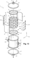
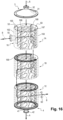
- the exchanger assembly 13 illustrated on the Figure 15 comprises a plurality of heat exchangers 1A to 1D stacked on top of each other. Each heat exchanger 1A to 1D is consistent with the heat exchanger of the figures 13 And 14 .
- the first outlet surface of the first heat exchanger 1A is connected to the first inlet surface 7 of the second heat exchanger 1B
- the first outlet surface of the second heat exchanger 1B is connected to the first inlet surface of the third heat exchanger 1C
- the first outlet surface of the third heat exchanger 1C is connected to the first inlet surface of the fourth heat exchanger 1D.
- the first fluid (arrow A) circulates successively through the first heat exchanger 1A, the second heat exchanger 1B, the third heat exchanger 1C and the fourth heat exchanger 1D.
- the second outlet surface of the fourth heat exchanger 1D is connected to the second inlet surface of the third heat exchanger 1C
- the second outlet surface of the third heat exchanger 1C is connected to the second inlet surface of the second heat exchanger 1B
- the second outlet surface of the second heat exchanger 1B is connected to the second inlet surface of the first heat exchanger 1A.
- the second fluid (arrow B) circulates successively through the fourth heat exchanger 1D, the third heat exchanger 1C, the second heat exchanger 1B and the first heat exchanger 1A.
- FIG. 16 schematically represents a variant of the exchanger assembly of the Figure 15 .
- the first outlet surface of the first heat exchanger 1A is connected to the first inlet surface of the second heat exchanger 1B and the first outlet surface of the second heat exchanger 1B is connected to the first inlet surface of the third heat exchanger 1C so that the first fluid (arrow A) circulates successively through the first heat exchanger 1A, the second heat exchanger 1B and the third heat exchanger 1C.
- the second outlet surface of the first heat exchanger 1A is connected to the second inlet surface of the second heat exchanger 1B and the second outlet surface of the second heat exchanger 1B is connected to the second inlet surface of the third heat exchanger 1C so that the second fluid successively circulates through the first heat exchanger 1A, the second heat exchanger 1B and the third heat exchanger 1C.
- Each heat exchanger 1A, 1B and 1C comprises an exchanger body 2 conforming to that of the heat exchanger 1 of the Figure 1 .
- each heat exchanger 1A, 1B and 1C further comprises an external casing 16 surrounding the exchanger body 2 and partitions connecting the external casing 16 to the exchanger body 2.
- the external casing 16 comprises a wall 161 of generally cylindrical shape of revolution surrounding the exchanger body 2.
- the wall 161 comprises a first wall portion 162 extending at a distance from and facing the second inlet surface 9 of the exchanger body 2 and a second wall portion 163 extends at a distance from and opposite the second outlet surface 10 of the exchanger body 2.
- Each heat exchanger 1A, 1B and 1C comprises partitions 165, 166, 167 and 168.
- the partitions delimit spaces 53 and 63 between the external casing 16 and the exchanger body 2.
- the partitions include a first partition 165 and a second partition 166.
- the first partition 165 and the second partition 166 delimit with the first wall portion 162 and the first inlet surface 9 an inlet space 53 intended to receive the second fluid at the inlet of the exchanger body 2.
- the first wall 9 and the partitions 165, 166 form the second inlet manifold 5.
- the partitions include a third partition 167 and a fourth partition 168.
- the third partition 167 and the fourth partition 168 delimit with the second wall portion 163 and the second outlet surface 10, an outlet space 63 intended to receive the second fluid leaving the exchanger body 2.
- the second wall portion 163 and the partitions 167 and 168 form the second outlet collector 6.
- the second fluid (arrow B) circulates successively through the first exchanger 1A, the second exchanger 1B then the third exchanger 1C.
- the exchanger assembly 13 comprises a plurality of separation plates 169.
- Each separation plate 169 is arranged between two successive heat exchangers in the stack (for example between the exchanger 1A and the exchanger 1B).
- each separation plate 169 has a C-shape.
- Each separation plate 169 prevents fluid communication between the inlet space 53 of a heat exchanger and the outlet space 63 of the following heat exchanger in the direction of circulation of the second fluid.
- the first outlet surface of one heat exchanger is connected to the first inlet surface of another adjacent heat exchanger in the stack so that the first fluid circulates successively through the heat exchangers of the stack.
- the second outlet surface of the other adjacent heat exchanger is connected to the second inlet surface of the heat exchanger so that the second fluid circulates successively through the heat exchangers of the stack.
Landscapes
- Engineering & Computer Science (AREA)
- Physics & Mathematics (AREA)
- Thermal Sciences (AREA)
- Mechanical Engineering (AREA)
- General Engineering & Computer Science (AREA)
- Chemical & Material Sciences (AREA)
- Manufacturing & Machinery (AREA)
- Materials Engineering (AREA)
- Heat-Exchange Devices With Radiators And Conduit Assemblies (AREA)
Claims (10)
- Wärmetauscher (1), umfassend einen Tauscherkörper (2), der von einer ersten Einlassfläche (7), einer ersten Auslassfläche (8), einer zweiten Einlassfläche (9) und einer zweiten Auslassfläche (10) begrenzt wird, wobei der Tauscherkörper (2) eine Trennwand (21) in Form eines Gyroids umfasst, die ein erstes Kanalnetz (22) für die Zirkulation eines ersten Fluids von der ersten Einlassfläche (7) zu der ersten Auslassfläche (8) und ein zweites Kanalnetz (23) für die Zirkulation eines zweiten Fluids von der zweiten Einlassfläche (9) zu der zweiten Auslassfläche (10) trennt, dadurch gekennzeichnet, dass
das erste Kanalnetz (22) erste Kanäle mit einem Querschnitt umfasst, der sich kontinuierlich zunehmend von der ersten Einlassfläche (7) zu der ersten Auslassfläche (8) ändert, und dass das zweite Kanalnetz (23) zweite Kanäle mit einem Querschnitt umfasst, der sich von der zweiten Eingangsfläche (9) zu der zweiten Ausgangsfläche (10) kontinuierlich abnehmend ändert. - Wärmetauscher (1) nach Anspruch 1, wobei der Tauscherkörper (2) eine erste Einlasswand (71) umfasst, die ein Eindringen des ersten Fluids durch die erste Einlassfläche (7) in das erste Kanalnetz (22) gestattet und ein Eindringen des ersten Fluids durch die erste Einlassfläche (7) in das zweite Kanalnetz (23) unterbindet.
- Wärmetauscher (1) nach Anspruch 2, umfassend einen ersten Einlassverteiler (3), um das erste Fluid bis zu der ersten Einlasswand (71) zuzuführen.
- Wärmetauscher (1) nach einem der Ansprüche 1 bis 3, wobei der Tauscherkörper (2) eine erste Auslasswand (81) umfasst, die eine Entnahme des ersten Fluids durch die erste Auslassfläche (8) aus dem ersten Kanalnetz (22) gestattet und eine Entnahme des zweiten Fluids durch die erste Auslassfläche (8) aus dem zweiten Kanalnetz (23) unterbindet.
- Wärmetauscher (1) nach Anspruch 4, umfassend einen ersten Auslassverteiler (4), um das erste Fluid durch die erste Auslasswand (81) zu entnehmen.
- Wärmetauscher (1) nach einem der Ansprüche 1 bis 5, wobei der Tauscherkörper (2) eine zweite Einlasswand (91) umfasst, die ein Eindringen des zweiten Fluids durch die zweite Einlassfläche (9) in das zweite Kanalnetz (23) gestattet und ein Eindringen des zweiten Fluids durch die zweite Einlassfläche (9) in das zweite Kanalnetz (23) unterbindet.
- Wärmetauscher nach Anspruch 6, umfassend einen zweiten Einlassverteiler (5), um das zweite Fluid durch die zweite Einlasswand (91) zuzuführen.
- Wärmetauscher nach einem der Ansprüche 1 bis 7, wobei der Tauscherkörper (2) eine zweite Auslasswand (101) umfasst, die eine Entnahme des zweiten Fluids durch die zweite Auslassfläche (10) aus dem zweiten Kanalnetz (23) gestattet und eine Entnahme des ersten Fluids durch die zweite Auslassfläche (10) aus dem ersten Kanalnetz (23) unterbindet.
- Wärmetauscher nach Anspruch 8, umfassend einen zweiten Auslassverteiler (6), um das zweite Fluid durch die zweite Auslasswand (10) zu entnehmen.
- Wärmetauscheranordnung (13), umfassend eine Vielzahl von Wärmetauschern (1A-1D) nach einem der Ansprüche 1 bis 9, einschließlich eines ersten Wärmetauschers (1A) und eines zweiten Wärmetauschers (1B), wobei die erste Auslassfläche (8) des ersten Wärmetauschers (1A) mit der ersten Einlassfläche (7) des zweiten Wärmetauschers (1B) verbunden ist, so dass das erste Fluid nacheinander durch den ersten Wärmetauscher (1A) und durch den zweiten Wärmetauscher (1B) strömt, und wobei die zweite Auslassfläche (10) des zweiten Wärmetauschers (1B) mit der zweiten Einlassfläche (9) des ersten Wärmetauschers (1A) verbunden ist, so dass das zweite Fluid nacheinander durch den zweiten Wärmetauscher (1B) und durch den ersten Wärmetauscher (1A) strömt.
Applications Claiming Priority (1)
| Application Number | Priority Date | Filing Date | Title |
|---|---|---|---|
| FR2100603A FR3119228B1 (fr) | 2021-01-22 | 2021-01-22 | Echangeur thermique comprenant un corps d’echangeur en gyroïde |
Publications (3)
| Publication Number | Publication Date |
|---|---|
| EP4033193A1 EP4033193A1 (de) | 2022-07-27 |
| EP4033193B1 true EP4033193B1 (de) | 2025-04-09 |
| EP4033193C0 EP4033193C0 (de) | 2025-04-09 |
Family
ID=74669169
Family Applications (1)
| Application Number | Title | Priority Date | Filing Date |
|---|---|---|---|
| EP22152808.6A Active EP4033193B1 (de) | 2021-01-22 | 2022-01-21 | Wärmetauscher mit einem aus einem gyroiden bestehenden austauschkörper |
Country Status (2)
| Country | Link |
|---|---|
| EP (1) | EP4033193B1 (de) |
| FR (1) | FR3119228B1 (de) |
Families Citing this family (6)
| Publication number | Priority date | Publication date | Assignee | Title |
|---|---|---|---|---|
| JP7785597B2 (ja) * | 2022-03-31 | 2025-12-15 | 本田技研工業株式会社 | 熱交換器及びその製造方法 |
| EP4609135A1 (de) | 2022-10-27 | 2025-09-03 | Casale Sa | Chemischer reaktor mit einem wärmetauscher |
| EP4425084A1 (de) * | 2023-02-28 | 2024-09-04 | Hyperganic Pte Ltd. | Rohr-in-kreisel-wärmetauscher |
| DE102023121426A1 (de) * | 2023-08-10 | 2025-02-13 | Rolls-Royce Solutions GmbH | Vorrichtung zur Führung von wenigstens zwei Fluidströmen, elektrochemisches System und Verfahren zum Herstellen einer Vorrichtung mit einem Wärmeübertragerkörper |
| US12372314B2 (en) * | 2023-09-22 | 2025-07-29 | Ford Global Technologies, Llc | Vehicle heat exchanger |
| DK181910B1 (en) * | 2024-02-09 | 2025-03-18 | Kk Wind Solutions As | Focused temperature regulation unit |
Citations (10)
| Publication number | Priority date | Publication date | Assignee | Title |
|---|---|---|---|---|
| KR20120027582A (ko) | 2010-09-13 | 2012-03-22 | 주식회사 와이제이씨 | 교차 형식의 세라믹 열교환기 모듈 및 이를 이용한 열교환기 시스템 |
| CN202747867U (zh) | 2012-07-13 | 2013-02-20 | 甘肃蓝科石化高新装备股份有限公司 | 一种全串联板壳式热交换器 |
| WO2017052798A1 (en) | 2015-09-25 | 2017-03-30 | Westinghouse Electric Company Llc | Heat exchanger |
| EP3211358A1 (de) | 2016-01-15 | 2017-08-30 | Hamilton Sundstrand Corporation | Wärmetauscherkanäle |
| CN206930198U (zh) | 2017-06-15 | 2018-01-26 | 上海蓝滨石化设备有限责任公司 | 一种模块化多流程可清洗全焊接板式换热器 |
| US20180187984A1 (en) | 2017-01-03 | 2018-07-05 | Titan Tensor LLC | Monolithic Bicontinuous Labyrinth Structures and Methods For Their Manufacture |
| US20190033013A1 (en) | 2016-03-30 | 2019-01-31 | Woodside Energy Technologies Pty Ltd | Heat exchanger and method of manufacturing a heat exchanger |
| US20200033070A1 (en) | 2018-07-25 | 2020-01-30 | Andreas Vlahinos | Minimal surface heat exchanger |
| WO2020058373A1 (en) | 2018-09-19 | 2020-03-26 | Firmenich Sa | Fragrance delivery device |
| US20200215480A1 (en) | 2019-01-09 | 2020-07-09 | Lawrence Livermore National Security, Llc | Hierarchical triply periodic minimal surface structures as heat exchangers and reactors |
Family Cites Families (3)
| Publication number | Priority date | Publication date | Assignee | Title |
|---|---|---|---|---|
| FR2661488A1 (fr) * | 1990-04-25 | 1991-10-31 | Vulcanic Sa | Echangeur de chaleur tridimensionnel a alimentation electrique. |
| US11892245B2 (en) * | 2014-10-07 | 2024-02-06 | General Electric Company | Heat exchanger including furcating unit cells |
| US10107555B1 (en) * | 2017-04-21 | 2018-10-23 | Unison Industries, Llc | Heat exchanger assembly |
-
2021
- 2021-01-22 FR FR2100603A patent/FR3119228B1/fr not_active Revoked
-
2022
- 2022-01-21 EP EP22152808.6A patent/EP4033193B1/de active Active
Patent Citations (10)
| Publication number | Priority date | Publication date | Assignee | Title |
|---|---|---|---|---|
| KR20120027582A (ko) | 2010-09-13 | 2012-03-22 | 주식회사 와이제이씨 | 교차 형식의 세라믹 열교환기 모듈 및 이를 이용한 열교환기 시스템 |
| CN202747867U (zh) | 2012-07-13 | 2013-02-20 | 甘肃蓝科石化高新装备股份有限公司 | 一种全串联板壳式热交换器 |
| WO2017052798A1 (en) | 2015-09-25 | 2017-03-30 | Westinghouse Electric Company Llc | Heat exchanger |
| EP3211358A1 (de) | 2016-01-15 | 2017-08-30 | Hamilton Sundstrand Corporation | Wärmetauscherkanäle |
| US20190033013A1 (en) | 2016-03-30 | 2019-01-31 | Woodside Energy Technologies Pty Ltd | Heat exchanger and method of manufacturing a heat exchanger |
| US20180187984A1 (en) | 2017-01-03 | 2018-07-05 | Titan Tensor LLC | Monolithic Bicontinuous Labyrinth Structures and Methods For Their Manufacture |
| CN206930198U (zh) | 2017-06-15 | 2018-01-26 | 上海蓝滨石化设备有限责任公司 | 一种模块化多流程可清洗全焊接板式换热器 |
| US20200033070A1 (en) | 2018-07-25 | 2020-01-30 | Andreas Vlahinos | Minimal surface heat exchanger |
| WO2020058373A1 (en) | 2018-09-19 | 2020-03-26 | Firmenich Sa | Fragrance delivery device |
| US20200215480A1 (en) | 2019-01-09 | 2020-07-09 | Lawrence Livermore National Security, Llc | Hierarchical triply periodic minimal surface structures as heat exchangers and reactors |
Non-Patent Citations (4)
| Title |
|---|
| "Master's Thesis, Arizona State University", 1 May 2018, article CHANDRASEKARAN GOKUL: "3D Printed Heat Exchangers - An Experimental Study", XP093357182 |
| "Master's Thesis, Técnico Lisboa", 1 July 2019, article GONÇALVES PEREIRA PASSOS ANDRÉ: "Laminar flow and heat transfer in triply periodic minimal surfaces", XP093357172 |
| ALAN H SCHOEN: "Infinite periodic minimal surfaces without self-intersections", NASA TECHNICAL NOTE TN D-5541, NASA, 1 May 1970 (1970-05-01), pages 1 - 100, XP055720607, Retrieved from the Internet <URL:https://ntrs.nasa.gov/archive/nasa/casi.ntrs.nasa.gov/19700020472.pdf> |
| FEMMER TIM, KUEHNE ALEXANDER J.C., WESSLING MATTHIAS: "Estimation of the structure dependent performance of 3-D rapid prototyped membranes", CHEMICAL ENGENEERING JOURNAL, ELSEVIER, AMSTERDAM, NL, vol. 273, 1 August 2015 (2015-08-01), AMSTERDAM, NL , pages 438 - 445, XP009563313, ISSN: 1385-8947, DOI: 10.1016/j.cej.2015.03.029 |
Also Published As
| Publication number | Publication date |
|---|---|
| EP4033193A1 (de) | 2022-07-27 |
| FR3119228A1 (fr) | 2022-07-29 |
| FR3119228B1 (fr) | 2023-03-24 |
| EP4033193C0 (de) | 2025-04-09 |
Similar Documents
| Publication | Publication Date | Title |
|---|---|---|
| EP4033193A1 (de) | Wärmetauscher mit einem aus einem gyroiden bestehenden austauschkörper | |
| EP3662222B1 (de) | Wärmetauscher avec distriteur | |
| FR2681419A1 (fr) | Echangeur de chaleur a faisceau tubulaire comportant plusieurs circuits de fluides. | |
| EP0430752A1 (de) | Wärmetauscher mit einer umfangsförmigen Zirkulation | |
| EP1558886B1 (de) | Verwaltungssystem für thermische Energie erzeugt durch einen Kraftfahrzeugwärmemotor | |
| FR2861166A1 (fr) | Echangeur de chaleur utilisant un fluide d'accumulation | |
| FR2912811A1 (fr) | Echangeur de chaleur pour fluides a circulation en u | |
| EP2808595B1 (de) | Behälter und sein Herstellungsverfahren | |
| EP1892492A2 (de) | Wärmetauschermodul, insbesondere für ein Kraftfahrzeug, das einen Haupt- und einen Nebenkühler umfasst, und System, das dieses Modul enthält | |
| EP3019808B1 (de) | Wärmetauscher | |
| EP2912396B1 (de) | Wärmetauscher, insbesondere für ein kraftfahrzeug | |
| EP1994353B1 (de) | Mehrkammer-wärmetauscher mit verbesserten sammelkasten | |
| FR3099237A1 (fr) | Echangeur thermique comprenant un corps d’echangeur en gyroïde | |
| WO2023135461A1 (fr) | Echangeur de chaleur monocorps | |
| EP3469206A1 (de) | Raketentriebwerkbrennkammer mit rippen mit variabler zusammensetzung | |
| EP2898279B1 (de) | Wärmetauscheranordnung | |
| EP0445006B1 (de) | Wärmetauscher mit kreisförmiger Strömung | |
| WO2014064079A1 (fr) | Boite collectrice pour échangeur de chaleur, notamment refroidisseur d'air de suralimentation de moteur de véhicule automobile | |
| FR2952944A1 (fr) | Procede de fabrication d'une piece metallique composite a renforts internes en fibres, preforme de mise en œuvre et piece metallique obtenue | |
| FR2821926A1 (fr) | Echangeur de chaleur a plaques, plaque appartenant a un tel echangeur et utilisation d'un tel echangeur | |
| EP3394545B1 (de) | Wärmetauscher, insbesondere für ein kraftfahrzeug | |
| EP4018146B1 (de) | Wärmetauscher, insbesondere für ein kraftfahrzeug, und verfahren zur herstellung eines solchen wärmetauschers | |
| WO2024121005A1 (fr) | Echangeur de chaleur à structure alvéolaire | |
| WO2024251862A1 (fr) | Dispositif d'échange thermique comprenant au moins un collecteur, système de conditionnement d'air et véhicule | |
| EP4679024A1 (de) | Thermisches speichersystem unter verwendung eines phasenwechselmaterials |
Legal Events
| Date | Code | Title | Description |
|---|---|---|---|
| PUAI | Public reference made under article 153(3) epc to a published international application that has entered the european phase |
Free format text: ORIGINAL CODE: 0009012 |
|
| STAA | Information on the status of an ep patent application or granted ep patent |
Free format text: STATUS: REQUEST FOR EXAMINATION WAS MADE |
|
| 17P | Request for examination filed |
Effective date: 20220121 |
|
| AK | Designated contracting states |
Kind code of ref document: A1 Designated state(s): AL AT BE BG CH CY CZ DE DK EE ES FI FR GB GR HR HU IE IS IT LI LT LU LV MC MK MT NL NO PL PT RO RS SE SI SK SM TR |
|
| GRAP | Despatch of communication of intention to grant a patent |
Free format text: ORIGINAL CODE: EPIDOSNIGR1 |
|
| STAA | Information on the status of an ep patent application or granted ep patent |
Free format text: STATUS: GRANT OF PATENT IS INTENDED |
|
| RIC1 | Information provided on ipc code assigned before grant |
Ipc: F28F 9/02 20060101ALI20240917BHEP Ipc: F28F 7/02 20060101ALI20240917BHEP Ipc: B33Y 80/00 20150101ALI20240917BHEP Ipc: F28F 13/08 20060101AFI20240917BHEP |
|
| INTG | Intention to grant announced |
Effective date: 20241010 |
|
| GRAS | Grant fee paid |
Free format text: ORIGINAL CODE: EPIDOSNIGR3 |
|
| GRAA | (expected) grant |
Free format text: ORIGINAL CODE: 0009210 |
|
| STAA | Information on the status of an ep patent application or granted ep patent |
Free format text: STATUS: THE PATENT HAS BEEN GRANTED |
|
| RAP3 | Party data changed (applicant data changed or rights of an application transferred) |
Owner name: NEXSON GROUP - INDUSTRY |
|
| AK | Designated contracting states |
Kind code of ref document: B1 Designated state(s): AL AT BE BG CH CY CZ DE DK EE ES FI FR GB GR HR HU IE IS IT LI LT LU LV MC MK MT NL NO PL PT RO RS SE SI SK SM TR |
|
| REG | Reference to a national code |
Ref country code: GB Ref legal event code: FG4D Free format text: NOT ENGLISH |
|
| REG | Reference to a national code |
Ref country code: CH Ref legal event code: EP |
|
| REG | Reference to a national code |
Ref country code: DE Ref legal event code: R096 Ref document number: 602022012732 Country of ref document: DE |
|
| REG | Reference to a national code |
Ref country code: IE Ref legal event code: FG4D Free format text: LANGUAGE OF EP DOCUMENT: FRENCH |
|
| U01 | Request for unitary effect filed |
Effective date: 20250506 |
|
| U07 | Unitary effect registered |
Designated state(s): AT BE BG DE DK EE FI FR IT LT LU LV MT NL PT RO SE SI Effective date: 20250512 |
|
| PG25 | Lapsed in a contracting state [announced via postgrant information from national office to epo] |
Ref country code: ES Free format text: LAPSE BECAUSE OF FAILURE TO SUBMIT A TRANSLATION OF THE DESCRIPTION OR TO PAY THE FEE WITHIN THE PRESCRIBED TIME-LIMIT Effective date: 20250409 |
|
| PG25 | Lapsed in a contracting state [announced via postgrant information from national office to epo] |
Ref country code: GR Free format text: LAPSE BECAUSE OF FAILURE TO SUBMIT A TRANSLATION OF THE DESCRIPTION OR TO PAY THE FEE WITHIN THE PRESCRIBED TIME-LIMIT Effective date: 20250710 Ref country code: NO Free format text: LAPSE BECAUSE OF FAILURE TO SUBMIT A TRANSLATION OF THE DESCRIPTION OR TO PAY THE FEE WITHIN THE PRESCRIBED TIME-LIMIT Effective date: 20250709 |
|
| PG25 | Lapsed in a contracting state [announced via postgrant information from national office to epo] |
Ref country code: PL Free format text: LAPSE BECAUSE OF FAILURE TO SUBMIT A TRANSLATION OF THE DESCRIPTION OR TO PAY THE FEE WITHIN THE PRESCRIBED TIME-LIMIT Effective date: 20250409 |
|
| PG25 | Lapsed in a contracting state [announced via postgrant information from national office to epo] |
Ref country code: HR Free format text: LAPSE BECAUSE OF FAILURE TO SUBMIT A TRANSLATION OF THE DESCRIPTION OR TO PAY THE FEE WITHIN THE PRESCRIBED TIME-LIMIT Effective date: 20250409 |
|
| PG25 | Lapsed in a contracting state [announced via postgrant information from national office to epo] |
Ref country code: RS Free format text: LAPSE BECAUSE OF FAILURE TO SUBMIT A TRANSLATION OF THE DESCRIPTION OR TO PAY THE FEE WITHIN THE PRESCRIBED TIME-LIMIT Effective date: 20250709 |
|
| PG25 | Lapsed in a contracting state [announced via postgrant information from national office to epo] |
Ref country code: IS Free format text: LAPSE BECAUSE OF FAILURE TO SUBMIT A TRANSLATION OF THE DESCRIPTION OR TO PAY THE FEE WITHIN THE PRESCRIBED TIME-LIMIT Effective date: 20250809 |
|
| PLBI | Opposition filed |
Free format text: ORIGINAL CODE: 0009260 |
|
| PG25 | Lapsed in a contracting state [announced via postgrant information from national office to epo] |
Ref country code: SM Free format text: LAPSE BECAUSE OF FAILURE TO SUBMIT A TRANSLATION OF THE DESCRIPTION OR TO PAY THE FEE WITHIN THE PRESCRIBED TIME-LIMIT Effective date: 20250409 |
|
| REG | Reference to a national code |
Ref country code: CH Ref legal event code: L10 Free format text: ST27 STATUS EVENT CODE: U-0-0-L10-L00 (AS PROVIDED BY THE NATIONAL OFFICE) Effective date: 20260114 |
|
| U20 | Renewal fee for the european patent with unitary effect paid |
Year of fee payment: 5 Effective date: 20251211 |
|
| PG25 | Lapsed in a contracting state [announced via postgrant information from national office to epo] |
Ref country code: CZ Free format text: LAPSE BECAUSE OF FAILURE TO SUBMIT A TRANSLATION OF THE DESCRIPTION OR TO PAY THE FEE WITHIN THE PRESCRIBED TIME-LIMIT Effective date: 20250409 |
|
| PLAX | Notice of opposition and request to file observation + time limit sent |
Free format text: ORIGINAL CODE: EPIDOSNOBS2 |
|
| PG25 | Lapsed in a contracting state [announced via postgrant information from national office to epo] |
Ref country code: SK Free format text: LAPSE BECAUSE OF FAILURE TO SUBMIT A TRANSLATION OF THE DESCRIPTION OR TO PAY THE FEE WITHIN THE PRESCRIBED TIME-LIMIT Effective date: 20250409 |
|
| 26 | Opposition filed |
Opponent name: ALFA LAVAL CORPORATE AB Effective date: 20260107 |
|
| PGFP | Annual fee paid to national office [announced via postgrant information from national office to epo] |
Ref country code: GB Payment date: 20260127 Year of fee payment: 5 |
|
| PLBB | Reply of patent proprietor to notice(s) of opposition received |
Free format text: ORIGINAL CODE: EPIDOSNOBS3 |
|
| RDAF | Communication despatched that patent is revoked |
Free format text: ORIGINAL CODE: EPIDOSNREV1 |