EP2808663A1 - Anomalienerkennungsvorrichtung, hybridfahrzeug, anomalienerkennungsverfahren und programm - Google Patents
Anomalienerkennungsvorrichtung, hybridfahrzeug, anomalienerkennungsverfahren und programm Download PDFInfo
- Publication number
- EP2808663A1 EP2808663A1 EP12866729.2A EP12866729A EP2808663A1 EP 2808663 A1 EP2808663 A1 EP 2808663A1 EP 12866729 A EP12866729 A EP 12866729A EP 2808663 A1 EP2808663 A1 EP 2808663A1
- Authority
- EP
- European Patent Office
- Prior art keywords
- temperature
- calculation means
- amount
- temperature sensor
- coordinate
- Prior art date
- Legal status (The legal status is an assumption and is not a legal conclusion. Google has not performed a legal analysis and makes no representation as to the accuracy of the status listed.)
- Withdrawn
Links
Images


Classifications
-
- G—PHYSICS
- G01—MEASURING; TESTING
- G01K—MEASURING TEMPERATURE; MEASURING QUANTITY OF HEAT; THERMALLY-SENSITIVE ELEMENTS NOT OTHERWISE PROVIDED FOR
- G01K15/00—Testing or calibrating of thermometers
- G01K15/007—Testing
-
- B—PERFORMING OPERATIONS; TRANSPORTING
- B60—VEHICLES IN GENERAL
- B60K—ARRANGEMENT OR MOUNTING OF PROPULSION UNITS OR OF TRANSMISSIONS IN VEHICLES; ARRANGEMENT OR MOUNTING OF PLURAL DIVERSE PRIME-MOVERS IN VEHICLES; AUXILIARY DRIVES FOR VEHICLES; INSTRUMENTATION OR DASHBOARDS FOR VEHICLES; ARRANGEMENTS IN CONNECTION WITH COOLING, AIR INTAKE, GAS EXHAUST OR FUEL SUPPLY OF PROPULSION UNITS IN VEHICLES
- B60K6/00—Arrangement or mounting of plural diverse prime-movers for mutual or common propulsion, e.g. hybrid propulsion systems comprising electric motors and internal combustion engines
- B60K6/20—Arrangement or mounting of plural diverse prime-movers for mutual or common propulsion, e.g. hybrid propulsion systems comprising electric motors and internal combustion engines the prime-movers consisting of electric motors and internal combustion engines, e.g. HEVs
- B60K6/42—Arrangement or mounting of plural diverse prime-movers for mutual or common propulsion, e.g. hybrid propulsion systems comprising electric motors and internal combustion engines the prime-movers consisting of electric motors and internal combustion engines, e.g. HEVs characterised by the architecture of the hybrid electric vehicle
- B60K6/48—Parallel type
-
- B—PERFORMING OPERATIONS; TRANSPORTING
- B60—VEHICLES IN GENERAL
- B60L—PROPULSION OF ELECTRICALLY-PROPELLED VEHICLES; SUPPLYING ELECTRIC POWER FOR AUXILIARY EQUIPMENT OF ELECTRICALLY-PROPELLED VEHICLES; ELECTRODYNAMIC BRAKE SYSTEMS FOR VEHICLES IN GENERAL; MAGNETIC SUSPENSION OR LEVITATION FOR VEHICLES; MONITORING OPERATING VARIABLES OF ELECTRICALLY-PROPELLED VEHICLES; ELECTRIC SAFETY DEVICES FOR ELECTRICALLY-PROPELLED VEHICLES
- B60L3/00—Electric devices on electrically-propelled vehicles for safety purposes; Monitoring operating variables, e.g. speed, deceleration or energy consumption
-
- B—PERFORMING OPERATIONS; TRANSPORTING
- B60—VEHICLES IN GENERAL
- B60W—CONJOINT CONTROL OF VEHICLE SUB-UNITS OF DIFFERENT TYPE OR DIFFERENT FUNCTION; CONTROL SYSTEMS SPECIALLY ADAPTED FOR HYBRID VEHICLES; ROAD VEHICLE DRIVE CONTROL SYSTEMS FOR PURPOSES NOT RELATED TO THE CONTROL OF A PARTICULAR SUB-UNIT
- B60W10/00—Conjoint control of vehicle sub-units of different type or different function
- B60W10/04—Conjoint control of vehicle sub-units of different type or different function including control of propulsion units
- B60W10/08—Conjoint control of vehicle sub-units of different type or different function including control of propulsion units including control of electric propulsion units, e.g. motors or generators
-
- B—PERFORMING OPERATIONS; TRANSPORTING
- B60—VEHICLES IN GENERAL
- B60W—CONJOINT CONTROL OF VEHICLE SUB-UNITS OF DIFFERENT TYPE OR DIFFERENT FUNCTION; CONTROL SYSTEMS SPECIALLY ADAPTED FOR HYBRID VEHICLES; ROAD VEHICLE DRIVE CONTROL SYSTEMS FOR PURPOSES NOT RELATED TO THE CONTROL OF A PARTICULAR SUB-UNIT
- B60W20/00—Control systems specially adapted for hybrid vehicles
- B60W20/50—Control strategies for responding to system failures, e.g. for fault diagnosis, failsafe operation or limp mode
-
- G—PHYSICS
- G01—MEASURING; TESTING
- G01K—MEASURING TEMPERATURE; MEASURING QUANTITY OF HEAT; THERMALLY-SENSITIVE ELEMENTS NOT OTHERWISE PROVIDED FOR
- G01K13/00—Thermometers specially adapted for specific purposes
-
- G—PHYSICS
- G01—MEASURING; TESTING
- G01K—MEASURING TEMPERATURE; MEASURING QUANTITY OF HEAT; THERMALLY-SENSITIVE ELEMENTS NOT OTHERWISE PROVIDED FOR
- G01K15/00—Testing or calibrating of thermometers
-
- G—PHYSICS
- G01—MEASURING; TESTING
- G01R—MEASURING ELECTRIC VARIABLES; MEASURING MAGNETIC VARIABLES
- G01R31/00—Arrangements for testing electric properties; Arrangements for locating electric faults; Arrangements for electrical testing characterised by what is being tested not provided for elsewhere
- G01R31/005—Testing of electric installations on transport means
- G01R31/006—Testing of electric installations on transport means on road vehicles, e.g. automobiles or trucks
-
- B—PERFORMING OPERATIONS; TRANSPORTING
- B60—VEHICLES IN GENERAL
- B60W—CONJOINT CONTROL OF VEHICLE SUB-UNITS OF DIFFERENT TYPE OR DIFFERENT FUNCTION; CONTROL SYSTEMS SPECIALLY ADAPTED FOR HYBRID VEHICLES; ROAD VEHICLE DRIVE CONTROL SYSTEMS FOR PURPOSES NOT RELATED TO THE CONTROL OF A PARTICULAR SUB-UNIT
- B60W2510/00—Input parameters relating to a particular sub-units
- B60W2510/08—Electric propulsion units
- B60W2510/087—Temperature
-
- B—PERFORMING OPERATIONS; TRANSPORTING
- B60—VEHICLES IN GENERAL
- B60W—CONJOINT CONTROL OF VEHICLE SUB-UNITS OF DIFFERENT TYPE OR DIFFERENT FUNCTION; CONTROL SYSTEMS SPECIALLY ADAPTED FOR HYBRID VEHICLES; ROAD VEHICLE DRIVE CONTROL SYSTEMS FOR PURPOSES NOT RELATED TO THE CONTROL OF A PARTICULAR SUB-UNIT
- B60W2710/00—Output or target parameters relating to a particular sub-units
- B60W2710/08—Electric propulsion units
- B60W2710/088—Temperature
-
- Y—GENERAL TAGGING OF NEW TECHNOLOGICAL DEVELOPMENTS; GENERAL TAGGING OF CROSS-SECTIONAL TECHNOLOGIES SPANNING OVER SEVERAL SECTIONS OF THE IPC; TECHNICAL SUBJECTS COVERED BY FORMER USPC CROSS-REFERENCE ART COLLECTIONS [XRACs] AND DIGESTS
- Y02—TECHNOLOGIES OR APPLICATIONS FOR MITIGATION OR ADAPTATION AGAINST CLIMATE CHANGE
- Y02T—CLIMATE CHANGE MITIGATION TECHNOLOGIES RELATED TO TRANSPORTATION
- Y02T10/00—Road transport of goods or passengers
- Y02T10/60—Other road transportation technologies with climate change mitigation effect
- Y02T10/62—Hybrid vehicles
Definitions
- the present invention relates to an abnormality detection apparatus, a hybrid vehicle, and an abnormality detection method, and a program.
- a temperature sensing device such as a thermistor, is used for sensing a temperature of an element configuring a circuit for an electric motor or an inverter in a hybrid vehicle.
- a technology for detecting an abnormality of such a temperature sensing means itself it is known, for example, to judge whether a value corresponding to an estimated temperature at a section heated by an electric current has changed more than a predetermined value, and to judge the temperature sensing means itself being abnormal if a sensed temperature, in the case of the temperature having changed more than the predetermined value, does not change more than a predetermined temperature range (refer to PTL 1).
- a temperature condition is specified with respect to a range for judging abnormality of a temperature sensing means.
- a thermistor to be commonly used as a temperature sensing device has an output performance that is non-linear in regard to a change in temperature. Therefore, the thermistor is designed and tuned in such a way that an output performance in a temperature range, where abnormality must be judged accurately, becomes as linear as possible. Accordingly, outside the predetermined temperature range of condition, which is a range for judging abnormality, the thermistor has a less output change in regard to an actual change in temperature so that there is a threat of making a misjudgment. In other words, since there exists a chance that the method disclosed in PTL 1 may make a misjudgment under condition lower than the predetermined temperature range, abnormality of the thermistor cannot appropriately be detected.
- the present invention is materialized against such a background, and thus it is an objective of the present invention to provide an abnormality detection apparatus, a hybrid vehicle, and an abnormality detection method, and a program, with which abnormality of a temperature sensor can appropriately be detected.
- the abnormality detection apparatus for detecting abnormality of a temperature sensor comprises: a heat amount calculation means which calculates the amount of heat generated in a predetermined time period from an object of sensing temperature by the temperature sensor; a temperature change calculation means which calculates the amount of temperature change of the object of sensing temperature in the predetermined time period; a coordinate value calculation means which calculates a coordinate value in a coordinate system represented by having the heat amount information calculated by the heat amount calculation means, on a coordinate axis, and having information on the amount of temperature change of the temperature sensor, calculated by the temperature change calculation means, on another coordinate axis; and an abnormality detection means which detects abnormality of the temperature sensor in the case where the coordinate value calculated by the coordinate value calculation means is included in a predetermined abnormality detection judgment area in the coordinate system continuously for a certain time.
- the predetermined abnormality detection judgment area is a coordinate area not included in a normal operation pattern area formed with a plurality of coordinate values obtained on the basis of relationships between an hour integration value calculated by use of a current value and an energization time of the object of sensing temperature in a predetermined time period, and the amount of temperature change of the object of sensing temperature in the predetermined time period, under conditions where the temperature sensor works normally; in the case where the coordinate value calculated by the coordinate value calculation means is continuously included for a certain time in a first abnormal temperature-change area, in which the amount of temperature change calculated by the temperature change calculation means is greater, in comparison with the coordinate values included in the normal operation pattern area, or in the case where the coordinate value calculated by the coordinate value calculation means is continuously included for a certain time in a second abnormal temperature-change area, in which the amount of temperature change calculated by the temperature change calculation means is smaller, in comparison with the coordinate values included in the normal operation pattern area; under either of the conditions described above, preferably the abnormality detection means detects abnormality of the temperature sensor.
- the hybrid vehicle comprises: a temperature sensor, a heat amount calculation means which calculates the amount of heat generated in a predetermined time period from an object of sensing temperature by the temperature sensor; a temperature change calculation means which calculates the amount of temperature change of the object of sensing temperature in the predetermined time period; a coordinate value calculation means which calculates a coordinate value in a coordinate system represented by having the heat amount information calculated by the heat amount calculation means, on a coordinate axis, and having information on the amount of temperature change of the temperature sensor, calculated by the temperature change calculation means, on another coordinate axis; and an abnormality detection means which detects abnormality of the temperature sensor in the case where the coordinate value calculated by the coordinate value calculation means is included in a predetermined abnormality detection judgment area in the coordinate system continuously for a certain time.
- the abnormality detection method for detecting abnormality of a temperature sensor comprises: a heat amount calculation step for calculating the amount of heat generated in a predetermined time period from an object of sensing temperature by the temperature sensor; a temperature change calculation step for calculating the amount of temperature change of the object of sensing temperature in the predetermined time period; a coordinate value calculation step for calculating a coordinate value in a coordinate system represented by having the heat amount information calculated by the heat amount calculation step, on a coordinate axis, and having information on the amount of temperature change of the temperature sensor, calculated by the temperature change calculation step, on another coordinate axis; and an abnormality detection step for detecting abnormality of the temperature sensor in the case where the coordinate value calculated by the coordinate value calculation step is included in a predetermined abnormality detection judgment area in the coordinate system continuously for a certain time.
- the computer program according to the present invention causes a computer to function for detecting abnormality of a temperature sensor as: a heat amount calculation means which calculates the amount of heat generated in a predetermined time period from an object of sensing temperature by the temperature sensor; a temperature change calculation means which calculates the amount of temperature change of the object of sensing temperature in the predetermined time period; a coordinate value calculation means which calculates a coordinate value in a coordinate system represented by having the heat amount information calculated by the heat amount calculation means, on a coordinate axis, and having information on the amount of temperature change of the temperature sensor, calculated by the temperature change calculation means, on another coordinate axis; and an abnormality detection means which detects abnormality of the temperature sensor in the case where the coordinate value calculated by the coordinate value calculation means is included in a predetermined abnormality detection judgment area in the coordinate system continuously for a certain time.
- an abnormality detection apparatus it becomes possible to provide an abnormality detection apparatus, a hybrid vehicle, and an abnormality detection method, and a program, with which abnormality of a temperature sensor can appropriately be detected.
- an abnormality detection apparatus a hybrid vehicle, and an abnormality detection method, and a program of the present invention are not limited to a configuration shown in the drawings.
- FIG. 1 is a configuration block diagram of substantial sections of a hybrid vehicle 1 according to an embodiment of the present invention.
- the hybrid vehicle 1 comprises; an engine 10, an engine ECU (Electronic Control Unit) 11, a clutch 12, an electric motor 13, an inverter 14, a battery 15, a transmission 16, an electric motor ECU 17, a hybrid ECU 18, a temperature sensor 19, and a wheel 20.
- an illustration of a configuration that is not directly related to an explanation is omitted in the configuration of FIG. 1 .
- the hybrid vehicle 1 has the temperature sensor 19 for sensing a temperature change of the inverter 14, and the hybrid ECU 18 detects abnormality of the temperature sensor 19 itself.
- the engine 10 is an example of an internal combustion engine, and the engine 10 is controlled by the engine ECU 11.
- the engine 10 combusts gasoline, diesel oil, CNG (Compressed Natural Gas), LPG (Liquefied Petroleum Gas), or alternative fuel and the like inside the engine 10 in order to generate power for rotating a shaft, and then transmits the generated power to the clutch 12.
- CNG Compressed Natural Gas
- LPG Liquefied Petroleum Gas
- the engine ECU 11 is a computer that cooperates with the electric motor ECU 17, by way of following an instruction coming from the hybrid ECU 18.
- the engine ECU 11 controls operation of the engine 10, for example, an amount of fuel consumption, timing of valve operation, and the like.
- the engine ECU 11 is structured with, for example, a CPU (Central Processing Unit), an ASIC (Application Specific Integrated Circuit), a micro-processor, or a DSP (Digital Signal Processor); and it internally includes an arithmetic section, a memory, an I/O (input/output) port, and so on.
- the clutch 12 is controlled by the hybrid ECU 18.
- the clutch 12 transmits a shaft output from the engine 10 to the wheel 20, by the intermediary of the electric motor 13 and the transmission 16.
- the clutch 12 transmits a shaft output of the engine 10 to the electric motor 13, by way of mechanically connecting a driving shaft of the engine 10 and a driving shaft of the electric motor 13.
- the clutch 12 enables the shaft of the engine 10 and the driving shaft of the electric motor 13 to rotate at each different rate.
- the clutch 12 mechanically connects the driving shaft of the engine 10 and the driving shaft of the electric motor 13.
- the clutch 12 disconnects the mechanical connection between the driving shaft of the engine 10 and the driving shaft of the electric motor 13.
- the clutch 12 is different from a clutch that a driver operates by way of using a clutch pedal.
- the electric motor 13 is a so-called electric motor-generator.
- the electric motor 13 generates drive power for rotating a shaft by use of electric power supplied from the inverter 14, and supplies the shaft output to the transmission 16.
- the electric motor 13 generates electric power by use of drive power for rotating the shaft, the drive power being supplied from the transmission 16; and then the electric power is supplied to the inverter 14.
- the electric motor 13 when the hybrid vehicle 1 is increasing speed or driving at a constant speed, the electric motor 13 generates the drive power for rotating the shaft, and supplies the shaft output to the transmission 16 to drive the hybrid vehicle 1 in cooperation with the engine 10.
- the motor 13 when the electric motor 13 is driven by the engine 10, or the hybrid vehicle 1 is slowing down or driving on a downhill or in a similar situation, the motor 13 operates as an electric power generator. At the time of operating as an electric power generator, the electric motor 13 generates electric power by use of drive power for rotating the shaft, the drive power being supplied from the transmission 16; in order to supply the electric power to the inverter 14.
- the inverter 14 is controlled by the electric motor ECU 17.
- the inverter 14 transforms direct-current voltage from the battery 15 into alternative-current voltage.
- the inverter 14 transforms alternative-current voltage from the electric motor 13 into direct-current voltage.
- the inverter 14 transforms direct-current voltage from the battery 15 into alternative-current voltage, and supplies the electric motor 13 with electric power.
- the inverter 14 transforms alternative-current voltage from the electric motor 13 into direct-current voltage.
- the inverter 14 plays a role of a rectifier and a voltage regulating device, for supplying the battery 15 with direct-current voltage.
- the battery 15 is a secondary battery that is chargeable and dischargeable.
- the battery 15 supplies the electric motor 13 with electric power by the intermediary of the inverter 14.
- the battery 15 is charged with the electric power generated by the electric motor 13.
- the transmission 16 has a semi-automatic transmission (not shown) that makes a choice among a plurality of gear ratios (transmission gear ratios), according to a gear-shift instruction signal coming from the hybrid ECU 18. While shifting the transmission gear ratio by use of the semi-automatic transmission, the transmission 16 transmits gear-shifted drive power of the engine 10 and drive power of the electric motor 13, to the wheel 20. Otherwise, while shifting the transmission gear ratio by use of the semi-automatic transmission, the transmission 16 transmits gear-shifted drive power of the engine 10 or drive power of the electric motor 13, to the wheel 20. Moreover, at the time of slowing down or driving on a downhill or in a similar situation, the transmission 16 transmits drive power from the wheel 20 to the electric motor 13. Incidentally, a gear position can manually be shifted to an optional gear in the semi-automatic transmission if a driver operates a shift unit 23.
- the electric motor ECU 17 is a computer that cooperates with the engine ECU 11 according to control by the hybrid ECU 18.
- the electric motor ECU 17 controls the electric motor 13 by way of controlling the inverter 14.
- the electric motor ECU 17 is structured with a CPU, an ASIC, a microprocessor, or a DSP; and it internally includes an arithmetic section, a memory, an I/O (input/output) port, and so on.
- the hybrid ECU 18 is an example of a computer.
- the hybrid ECU 18 obtains various information necessary for hybrid driving (such as, information on accelerator position, information on braking operation, information on vehicle speed, information on gear position, information on engine revolution rate, charging condition, and the like).
- the hybrid ECU 18 controls the clutch 12, also controls the transmission 16 by way of supplying a gear-shift instruction signal, provides the electric motor ECU 17 with a control instruction on the electric motor 13 and the inverter 14, and provides the engine ECU 11 with a control instruction on the engine 10.
- the hybrid ECU 18 obtains temperature information of the inverter 14 and current value information to be input into the inverter 14, and then detects abnormality of the temperature sensor 19 on the basis of the information obtained. Incidentally, details of this process (hereinafter, called 'abnormality detection process') are described later.
- the hybrid ECU 18 is structured with a CPU, an ASIC, a microprocessor, or a DSP; and it internally includes an arithmetic section, a memory, an I/O (input/output) port, and so on.
- a program to be executed by the hybrid ECU 18 can be installed in advance in the hybrid ECU 18 as a computer.
- the engine ECU 11, the electric motor ECU 17, and the hybrid ECU 18 are connected one another, through a bus that is in conformity with a standard specification such as CAN (Control Area Network).
- CAN Controller Area Network
- the temperature sensor 19 is a sensor for measuring a temperature of a main circuit element (for example, IGBT: Insulated Gate Bipolar Transistor) and the like, which configures the inverter 14. An output of detection coming from the temperature sensor 19 is loaded into the hybrid ECU 18, by the intermediary of the electric motor ECU 17. Incidentally, a configuration may be implemented in such a way that an output of detection from the temperature sensor 19 is loaded directly into the hybrid ECU 18.
- the temperature sensor 19 is constructed with a thermo-sensor such as; for example, a thermocouple, a thermistor, a thermostatic diode (diode thermometer).
- the wheel 20 is a driving wheel that transmits driving power to a roadway surface. Incidentally, though only one wheel 20 is illustrated in FIG. 1 , the hybrid vehicle 1 actually has a plurality of wheels 20.
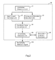
- FIG. 2 is a block diagram showing an example of functional configuration of the hybrid ECU 18 represented in FIG. 1 , for implementation of an abnormality detection process.
- the hybrid ECU 18 executes a predetermined program, implemented are functions of an information obtainment unit 31, a heat amount estimation unit 32 (a heat amount calculation means described in the claims), a temperature deviation calculation unit 33 (a temperature change calculation means described in the claims), a coordinate value calculation unit 34 (a coordinate value calculation means described in a claim), and an abnormality detection unit 35 (an abnormality detection means described in the claims).
- abnormality judgment area data 36 to which the abnormality detection unit 35 refers, is stored in the non-volatile memory placed inside the hybrid ECU 18.
- the information obtainment unit 31 obtains information necessary for judging abnormality of the temperature sensor 19. Concretely to describe, the information obtainment unit 31 obtains; information that shows a transition of a current value in a predetermined time period with the current being input into the inverter 14 in a predetermined time period, time-wise (energization time) information with a current input into the inverter 14 in a predetermined time period, and temperature information of the temperature sensor 19 in a predetermined time period.
- the predetermined time period in this context means a period of, for example, 10 seconds, 20 seconds, and the like.
- the information obtainment unit 31 outputs current value information (A) in the predetermined time period, and energization time information (S) in the predetermined time period, to the heat amount estimation unit 32. In the meantime, the information obtainment unit 31 outputs information (Te) that shows a transition of a temperature sensed by the temperature sensor 19 in the predetermined time period, to the temperature deviation calculation unit 33.
- the heat amount estimation unit 32 estimates the amount of heat flowing into the inverter 14.
- the heat amount estimation unit 32 calculates the amount of heat generated from the inverter 14 on the basis of the current value information (A) in the predetermined time period and the energization time information (S) in the predetermined time period, both the pieces of information being output from the information obtainment unit 31.
- the amount of heat is calculated, for example, as an hour integration value by integrating the square of current value and the energization time. Incidentally, the current value may be the cube instead.
- the heat amount estimation unit 32 outputs the hour integration value information (Y ⁇ A2 ⁇ S ⁇ ) that has been calculated, to the coordinate value calculation unit 33.
- the temperature deviation calculation unit 33 calculates a deviation of the temperature in the predetermined time period for assessing a temperature change of the inverter 14, the temperature being sensed by the temperature sensor 19.
- the temperature deviation calculation unit 33 identifies a maximum temperature (Max) and a minimum temperature (Min) that the temperature sensor 19 has sensed in the predetermined time period, on the basis of the temperature information (T) output by the information obtainment unit 31, and calculates an absolute value of a difference between these temperature values as temperature deviation information ( ⁇ T
- the coordinate value calculation unit 34 calculates a coordinate value, in the case of having the hour integration value (Y) on an X-axis and the temperature deviation (AT) on a Y-axis.
- the coordinate value calculation unit 34 calculates a coordinate value (Xn, Ym) on the basis of the hour integration value information (Y ⁇ A2 ⁇ S ⁇ ) output by the heat amount estimation unit 32, and the temperature deviation information ( ⁇ T
- the abnormality detection unit 35 records the coordinate value (Xn, Ym) output by the coordinate value calculation unit 34, in a memory; and if the coordinate value (Xn, Ym) is continuously included within the abnormality judgment area data 36 for a certain time, the abnormality detection unit 35 detects abnormality of the temperature sensor 19. In the case of having detected abnormality of the temperature sensor 19, the abnormality detection unit 35 outputs an abnormality detection signal SG. In the case of having detected abnormality, the hybrid vehicle 1, for example, turns on a dedicated LED lamp and the like, or otherwise alarms a sound and so on in order to notify a driver of the abnormality of the temperature sensor 19.
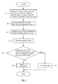
- FIG. 3 is a flowchart showing an abnormality detection process on temperature sensor 19, which is executed by the hybrid ECU 18 represented in FIG. 1 .
- steps from 'START' to 'END' in the flowchart of FIG. 3 represent processing of one cycle. Even though the processing reaches 'END', the processing starts again if conditions for 'START' are fulfilled.
- Step S1 For example, if once a drive key is operated and the hybrid ECU 18 gets started, the hybrid ECU 18 executes the predetermined program. Then, if the functions shown in FIG. 2 become ready for practice, operation progresses to Step S1.
- Step S1 The information obtainment unit 31 of the hybrid ECU 18 obtains the transition of the temperature of the main circuit element, configuring the inverter 14, in the predetermined time period, on the basis of the temperature information notified from the temperature sensor 19; and also obtains the transition of the current value in the predetermined time period, with the current being input into the inverter 14. After obtaining the temperature of the main circuit element, configuring the inverter 14, and also the current value, with the current being input into the inverter 14, in the predetermined time period, the hybrid ECU 18 shifts its operation to Step S2.
- Step S2 The heat amount estimation unit 32 of the hybrid ECU 18 estimates the amount of heat to be input into the inverter 14, on the basis of the current value and the energization time, obtained at Step S1.
- the amount of heat to be input into the inverter 14 can be obtained by way of calculating the hour integration value information (Y ⁇ A2 ⁇ S ⁇ ) described above.
- Step S3 The temperature deviation calculation unit 33 of the hybrid ECU 18 calculates the amount of temperature change of the inverter 14, obtained at Step S1.
- the amount of temperature change can be calculated by way of calculating the temperature deviation information ( ⁇ T
- Step S2 and Step S3 may be executed in reversed order, or these steps may be executed in parallel.
- Step S4 The coordinate value calculation unit 34 of the hybrid ECU 18 records the coordinate value (Xn, Ym) in a coordinate system, into an internal memory; the coordinate system being represented by way of having the hour integration value information (Y ⁇ A2 ⁇ S ⁇ ), calculated at Step S2, on an X-axis and the temperature deviation information ( ⁇ T
- Step S5 The abnormality detection unit 35 of the hybrid ECU 18 makes a judgment on whether or not the coordinate value (Xn, Ym) is continuously included within the abnormality judgment area data 36 for a certain time; the coordinate value (Xn, Ym) having been recorded into the internal memory at Step S4.
- Step S6 In the case of having judged at Step S5 that it is included (YES at Step S5), the abnormality detection unit 35 of the hybrid ECU 18 turns on a dedicated LED lamp and the like, for notifying of abnormality of the temperature sensor 19, with an output of the abnormality detection signal SG; or otherwise informing a driver of the hybrid vehicle 1 of the same by use of a sound, so that the abnormality detection process finishes (END). Incidentally, even in the case where the drive key is so operated as to stop the hybrid ECU 18, the abnormality detection process finishes (END).
- Step S7 In the case of having judged at Step S5 that it is not included (NO at Step S5), the abnormality detection unit 35 of the hybrid ECU 18 makes a judgment that the temperature sensor 19 has no abnormality and then the abnormality detection process finishes (END).
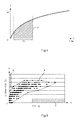
- FIG. 4 is an example of a diagram in which an X-axis represents time (TIME) of energizing the main circuit element of the inverter 14 shown in FIG. 1 , and meanwhile a Y-axis represents the square of a current value of a current (A2), the current flowing into the main circuit element of the inverter 14.
- TIME time
- A2 current value of a current
- the amount of heat energy flowing into the main circuit element of the inverter 14 for a predetermined time period T1 corresponds to an area of a shaded section 'S' shown in FIG. 4 .
- FIG. 5 is an example of a diagram represented by way of having an X-axis with hour integration value information (Y ⁇ A2 ⁇ S ⁇ ) and a Y-axis with temperature deviation information ( ⁇ T
- a normal operation pattern area 'A' shows a coordinate area represented by connecting outer circumferential dots of a plurality of coordinate values obtained through experiments of a variety of driving patterns with the hybrid vehicle 1.
- abnormality judgment areas 'B' and 'C' shown in FIG. 5 are areas outside the normal operation pattern area 'A'. If the coordinate value is continuously included in either of those areas for a certain time, it means that the abnormality detection unit 35 of the hybrid ECU 18 detects abnormality of the temperature sensor 19.
- the coordinate value calculated by the coordinate value calculation unit 34 of the hybrid ECU 18 is included in the abnormality judgment area 'B' shown in FIG. 5 , it means that a large change in temperature is observed, in comparison with a temperature change under normal conditions. Namely, in this case, even though the current flows less through the inverter 14 so that only a less amount of energy (heat amount) flows into the main circuit element of the inverter 14, a large change is observed in the temperature sensed by the temperature sensor 19, in comparison with a temperature change under normal conditions.
- FIG. 6 is a diagram that shows an example of a change in temperature included in the abnormality judgment area 'B' shown in FIG. 5 .
- an X-axis represents time (Time) of energizing the main circuit element of the inverter 14 shown in FIG. 1
- a Y-axis represents a change in temperature (deg C) of the main circuit element of the inverter 14, the change in temperature being sensed by the temperature sensor 19.
- 'T1' shown in FIG. 6 is the same predetermined time period as 'T1' in FIG. 4 .
- 'Te2' shown in FIG. 6 is a threshold for abnormality judgment.
- the threshold for abnormality judgment corresponds to the abnormality judgment area 'B' shown in FIG. 5 .
- the threshold for abnormality judgment is determined according to a coordinate area represented by connecting outer circumferential dots of a plurality of coordinate values obtained through experiments of a variety of driving patterns, under conditions where the temperature sensor 19 works normally.
- 'Te3' shown in FIG. 6 is a difference between a minimum temperature (Min) and a maximum temperature (Max) with respect to a temperature of the main circuit element of the inverter 14, sensed by the temperature sensor 19 in the predetermined time period 'T1'.
- FIG. 6 shows, it is observed that a change in temperature exceeds an area range of 'Te2'. Therefore, if the behavior shown in FIG. 6 is continuously observed for a certain time, it means that a coordinate value is included in the abnormality judgment area 'B' shown in FIG. 5 . As a result, the abnormality detection unit 35 of the hybrid ECU 18 detects abnormality of the temperature sensor 19.
- FIG. 7 is a diagram that shows an example of a change in temperature included in the abnormality judgment area 'C' shown in FIG. 5 .
- an X-axis represents time (Time) of energizing the main circuit element of the inverter 14 shown in FIG. 1
- a Y-axis represents a change in temperature (deg C) of the main circuit element of the inverter 14, the change in temperature being sensed by the temperature sensor 19.
- 'T1' shown in FIG. 7 is the same predetermined time period as 'T1' in FIG. 4 .
- 'Te4' shown in FIG. 7 is a threshold for abnormality judgment.
- the threshold for abnormality judgment corresponds to the abnormality judgment area 'C' shown in FIG. 5 .
- the threshold for abnormality judgment is determined according to a coordinate area represented by connecting outer circumferential dots of a plurality of coordinate values obtained through experiments of a variety of driving patterns, under conditions where the temperature sensor 19 works normally.
- 'Te5' shown in FIG. 7 is a difference between a minimum temperature (Min) and a maximum temperature (Max) with respect to a temperature of the main circuit element of the inverter 14, sensed by the temperature sensor 19 in the predetermined time period 'T1'.
- FIG. 7 shows, it is continuously observed for a certain time that a change in temperature does not exceed an area range of 'Te4.' In this case, a coordinate value is included in the abnormality judgment area 'C' shown in FIG. 5 so that the abnormality detection unit 35 of the hybrid ECU 18 detects abnormality of the temperature sensor 19.
- the hybrid ECU 18 as an example of an abnormality detection apparatus for detecting abnormality of the temperature sensor 19 includes: the heat amount calculation unit 32 (a heat amount calculation means) which calculates the amount of heat generated in the predetermined time period from the main circuit element of the inverter 14 as an object of sensing temperature by the temperature sensor 19; the temperature deviation calculation unit 33 (a temperature change calculation means) which calculates the amount of temperature change of the main circuit element of the inverter 14 in the predetermined time period; the coordinate value calculation unit 34 (a coordinate value calculation means) which calculates the coordinate value in the coordinate system represented by having the heat amount information calculated by the heat amount calculation unit 32 on a coordinate axis and having the temperature deviation information ( ⁇ T
- the abnormality judgment area 'B' or 'C' is a coordinate area not included in the normal operation pattern area 'A' formed with a plurality of coordinate values obtained on the basis of relationships between the hour integration value information (Y ⁇ A2 ⁇ S ⁇ ) (an hour integration value), calculated by use of the current value and the energization time of the main circuit element of the inverter 14 in the predetermined time period, and the temperature deviation information ( ⁇ T
- the hour integration value information Y ⁇ A2 ⁇ S ⁇
- the abnormality detection unit 35 detects abnormality of the temperature sensor 19.
- the abnormality detection process may be carried out by using only one of the abnormality judgment areas.
- a use of a thermistor as the temperature sensor 19 restricts a range of accurate detection so that the same behavior may be observed outside the range, under normal conditions as well as abnormal conditions.
- a use of a thermostatic diode (diode thermometer) further reduces a risk of a detection error in comparison with the case of using a thermistor.
- hybrid vehicle 1 having the hybrid ECU 18 described above, an abnormality detection method to be executed by the hybrid ECU 18, and various programs for operating a computer as the hybrid ECU 18 produce the same effects as each effect described above.
- the hybrid ECU 18 may be configured with a general-purpose information processing unit to be operated by a predetermined program.
- a general-purpose information processing unit has a memory, a CPU, an I/O port and the like.
- the CPU of the general-purpose information processing unit loads a control program as a predetermined program, from the memory and the like, and then executes the control program.
- a function of the hybrid ECU 18 is materialized in the general-purpose information processing unit.
- another function can also be materialized by use of a general-purpose information processing unit and a program, as far as the function can be materialized with software.
- an ASIC, a microprocessor, a DSP and the like may also be used.
- control program to be executed by the general-purpose information processing unit may be a program stored in a memory and the like of the general-purpose information processing unit before a delivery of the hybrid ECU 18, or may be a program stored in the memory and the like of the general-purpose information processing unit after the delivery of the hybrid ECU 18. Moreover, alternatively a part of the control program may be stored in the memory and the like of the general-purpose information processing unit after the delivery of the hybrid ECU 18.
- the control program to be stored in the memory and the like of the general-purpose information processing unit, after the delivery of the hybrid ECU 18, may be a program installed, having been stored in a computer-readable record medium such as a CD-ROM; or may be a program installed, having been downloaded by the intermediary of a transmission medium such as the Internet.
- control program includes not only a program that can directly be executed by the general-purpose information processing unit, but also a program that becomes ready for execution at the time of being installed in a hard disc and so on. Furthermore, the control program also includes a program that is compressed or encrypted.
- the function of the hybrid ECU 18 is materialized with the general-purpose information processing unit and the program in this way, it becomes possible to flexibly deal with mass production as well as a specification change (or a design change).
- the temperature sensor 19 is illustrated in the inverter 14, the illustration does not limit an installation position to an internal part of the inverter 14.
- the temperature sensor 19 may be placed at an external part of the inverter 14 in order to measure a temperature of a chassis of the inverter 14 for indirectly estimating a temperature of the inverter 14.
- the temperature sensor 19 may measure a temperature of a surrounding atmosphere of the installation position of the inverter 14 so that the temperature of the inverter 14 can indirectly be estimated by way of measuring the temperature of a surrounding atmosphere of the installation position of the inverter 14.
- a camera unit may be installed instead of the temperature sensor 19 in order to externally measure a temperature of the chassis of the inverter 14 so that an image analysis method such as thermography is applied.
- the abnormality detection is carried out for the temperature sensor 19 of the inverter 14, the abnormality detection can be applied to a temperature sensor installed for any unit other than the inverter 14.
- the same can be applied to abnormality detection for a temperature sensor (not shown) for detecting a temperature of an element included in the electric motor 13.
- the temperature may be estimated according to a value of a current input into the electric motor 13; or alternatively the amount of heat generated from the electric motor 13 may be estimated according to a mechanical output that is calculated by way of multiplying the product of the number of revolutions and torque of the electric motor 13 by a predetermined coefficient.
- the engine 10 is explained as an internal combustion engine, it may also be any one of other thermal engines including an external combustion engine.
- each ECU (the engine ECU 11, the electric motor ECU 17, and the hybrid ECU 18) may be materialized as an integrated ECU including all these functions, or otherwise another ECU created by further dividing the function of each ECU may be newly provided.
- the function to be materialized in the hybrid ECU 18, shown in FIG. 2 may be materialized in the electric motor ECU 17.
- the hybrid vehicle 1 is described as a machine of a parallel method, alternatively it may be a machine of a series method in which an engine is used for generating electricity and a motor is used for only driving a wheel axis and regeneration, or it may be a machine of a split method in which a drive power from the engine is divided by a power dividing mechanism using a planetary gear and the like, in order to distribute the power to a power generator and the motor.
- the program to be executed by the computer may be a program in which operation steps are chronologically executed in order as explained in this specification document; or it may be another program in which operation steps are executed in parallel, or executed at a time required, such as at the time of a call invoked.
Landscapes
- Engineering & Computer Science (AREA)
- Chemical & Material Sciences (AREA)
- Combustion & Propulsion (AREA)
- Transportation (AREA)
- Mechanical Engineering (AREA)
- General Physics & Mathematics (AREA)
- Physics & Mathematics (AREA)
- Automation & Control Theory (AREA)
- Health & Medical Sciences (AREA)
- General Health & Medical Sciences (AREA)
- Biomedical Technology (AREA)
- Life Sciences & Earth Sciences (AREA)
- Sustainable Development (AREA)
- Sustainable Energy (AREA)
- Power Engineering (AREA)
- Electric Propulsion And Braking For Vehicles (AREA)
- Measuring Temperature Or Quantity Of Heat (AREA)
- Hybrid Electric Vehicles (AREA)
Applications Claiming Priority (2)
| Application Number | Priority Date | Filing Date | Title |
|---|---|---|---|
| JP2012015833A JP5770649B2 (ja) | 2012-01-27 | 2012-01-27 | 異常検出装置、ハイブリッド自動車および異常検出方法、並びにプログラム |
| PCT/JP2012/074379 WO2013111380A1 (ja) | 2012-01-27 | 2012-09-24 | 異常検出装置、ハイブリッド自動車および異常検出方法、並びにプログラム |
Publications (2)
| Publication Number | Publication Date |
|---|---|
| EP2808663A1 true EP2808663A1 (de) | 2014-12-03 |
| EP2808663A4 EP2808663A4 (de) | 2015-09-16 |
Family
ID=48873129
Family Applications (1)
| Application Number | Title | Priority Date | Filing Date |
|---|---|---|---|
| EP12866729.2A Withdrawn EP2808663A4 (de) | 2012-01-27 | 2012-09-24 | Anomalienerkennungsvorrichtung, hybridfahrzeug, anomalienerkennungsverfahren und programm |
Country Status (5)
| Country | Link |
|---|---|
| US (1) | US20140376587A1 (de) |
| EP (1) | EP2808663A4 (de) |
| JP (1) | JP5770649B2 (de) |
| CN (1) | CN104114987B (de) |
| WO (1) | WO2013111380A1 (de) |
Cited By (1)
| Publication number | Priority date | Publication date | Assignee | Title |
|---|---|---|---|---|
| CN107662499A (zh) * | 2016-07-28 | 2018-02-06 | 长城汽车股份有限公司 | 纯电动汽车整车故障下电控制方法及系统 |
Families Citing this family (22)
| Publication number | Priority date | Publication date | Assignee | Title |
|---|---|---|---|---|
| US9783137B2 (en) * | 2013-10-30 | 2017-10-10 | Powervoice Co., Ltd. | Sound QR system for vehicular services |
| KR101509971B1 (ko) * | 2013-11-15 | 2015-04-07 | 현대자동차주식회사 | 수소 탱크 온도 이상 대처 방법 및 이를 위한 안전강화장치 |
| JP6119647B2 (ja) * | 2014-03-13 | 2017-04-26 | トヨタ自動車株式会社 | 電動車両 |
| JP6316656B2 (ja) * | 2014-05-22 | 2018-04-25 | 日野自動車株式会社 | 異常検出装置および異常検出方法 |
| JP6367647B2 (ja) * | 2014-08-20 | 2018-08-01 | 日野自動車株式会社 | ハイブリッド自動車および温度管理方法 |
| KR101587357B1 (ko) * | 2014-09-01 | 2016-01-20 | 엘에스산전 주식회사 | 차량 충전 장치 및 충전 방법 |
| JP6164197B2 (ja) * | 2014-11-13 | 2017-07-19 | 株式会社デンソー | 電子制御装置 |
| CN104648406B (zh) * | 2015-01-29 | 2017-04-05 | 长城汽车股份有限公司 | 诊断车速故障的方法及系统 |
| KR102092159B1 (ko) | 2015-02-25 | 2020-03-24 | 엘에스산전 주식회사 | 인버터의 트립 제어 방법 |
| KR101684129B1 (ko) * | 2015-06-15 | 2016-12-07 | 현대자동차주식회사 | 전동식 워터펌프 다단 제어 방법 |
| CN105067150A (zh) * | 2015-07-22 | 2015-11-18 | 株洲南车时代电气股份有限公司 | 一种动车轴箱温度检测系统及方法 |
| JP6428547B2 (ja) * | 2015-09-25 | 2018-11-28 | 株式会社デンソー | 温度検出装置 |
| JP6443372B2 (ja) * | 2016-03-24 | 2018-12-26 | トヨタ自動車株式会社 | 車両用ソフトウェア割当てシステム |
| EP3823242A1 (de) * | 2016-04-06 | 2021-05-19 | Karamba Security | Zentralisierte steuergeräteverwaltung und anomaliedetektion |
| US10737575B2 (en) * | 2017-11-22 | 2020-08-11 | Ford Global Technologies, Llc | Power device parameter adjustment |
| KR102383437B1 (ko) * | 2017-12-05 | 2022-04-07 | 현대자동차주식회사 | 차량 모터 제어 장치, 그를 포함한 시스템 및 그 방법 |
| JP7103164B2 (ja) * | 2018-10-31 | 2022-07-20 | オムロン株式会社 | 温度異常検知システム、温度異常検知方法、およびプログラム |
| JP7134160B2 (ja) * | 2019-12-18 | 2022-09-09 | 本田技研工業株式会社 | ガス制御装置及びガス制御方法 |
| CN111478646B (zh) * | 2020-04-28 | 2023-04-14 | 重庆长安新能源汽车科技有限公司 | 电动车电机系统温度保护方法、系统、电动车及存储介质 |
| CN112229543B (zh) * | 2020-10-23 | 2026-04-24 | 武汉蔚来能源设备有限公司 | 判断电池温度传感器状态的方法和装置、介质、车辆以及服务器 |
| TWI819760B (zh) * | 2021-09-22 | 2023-10-21 | 日商斯庫林集團股份有限公司 | 基板處理裝置、異常檢測方法及異常檢測程式 |
| CN120970853A (zh) * | 2025-10-17 | 2025-11-18 | 深圳市英博伟业科技有限公司 | 温度传感器的校正方法、装置、电子设备及存储介质 |
Family Cites Families (19)
| Publication number | Priority date | Publication date | Assignee | Title |
|---|---|---|---|---|
| JPH10159639A (ja) * | 1996-11-27 | 1998-06-16 | Toyota Motor Corp | 温度センサの異常を検出する方法 |
| JP3566147B2 (ja) * | 1999-09-14 | 2004-09-15 | 本田技研工業株式会社 | ハイブリッド車両の冷却ファン故障検知装置 |
| JP3409756B2 (ja) | 1999-11-02 | 2003-05-26 | トヨタ自動車株式会社 | 車両の電動パワーステアリング装置 |
| JP4872143B2 (ja) * | 2000-05-01 | 2012-02-08 | トヨタ自動車株式会社 | 二次電池用の冷却装置 |
| JP2004251186A (ja) * | 2003-02-20 | 2004-09-09 | Honda Motor Co Ltd | 内燃機関の冷却水の温度センサの故障を診断する装置 |
| JP2005011757A (ja) * | 2003-06-20 | 2005-01-13 | Toyota Motor Corp | 二次電池の温度異常検知装置および異常検知方法 |
| US7274007B2 (en) * | 2003-09-25 | 2007-09-25 | W.E.T. Automotive Systems Ltd. | Control system for operating automotive vehicle components |
| JP4325367B2 (ja) * | 2003-11-10 | 2009-09-02 | 株式会社デンソー | 排気温度センサの故障検出装置 |
| JP2006053024A (ja) * | 2004-08-11 | 2006-02-23 | Sanyo Electric Co Ltd | 温度補正処理装置 |
| JP5314235B2 (ja) * | 2006-03-07 | 2013-10-16 | プライムアースEvエナジー株式会社 | 二次電池の温度制御装置、二次電池の加温システム、およびプログラム |
| JP2007311065A (ja) * | 2006-05-16 | 2007-11-29 | Toyota Motor Corp | 電池装置、これを搭載した車両、および電池装置の異常判定方法 |
| US7953530B1 (en) * | 2006-06-08 | 2011-05-31 | Pederson Neal R | Vehicle diagnostic tool |
| JP4963052B2 (ja) * | 2006-09-22 | 2012-06-27 | Udトラックス株式会社 | 排気温度センサの異常検出装置 |
| JP5369371B2 (ja) * | 2006-10-03 | 2013-12-18 | 日産自動車株式会社 | 電池冷却システムの故障診断装置 |
| JP2009229128A (ja) * | 2008-03-19 | 2009-10-08 | Hitachi Ltd | インバータ回路の温度センサ診断装置 |
| JP2010220374A (ja) * | 2009-03-17 | 2010-09-30 | Toyota Motor Corp | 温度センサの断線を検知する方法 |
| JP2011007542A (ja) * | 2009-06-24 | 2011-01-13 | Toyota Industries Corp | 温度センサ異常判定装置 |
| JP2011085477A (ja) * | 2009-10-15 | 2011-04-28 | Toyota Motor Corp | 温度センサの異常判定装置およびこれを備える駆動装置並びに温度センサの異常判定方法 |
| CN101949746B (zh) * | 2010-08-30 | 2011-12-28 | 中国人民解放军后勤工程学院 | 一种视觉温度计的自动检定方法及温度计自动检定仪 |
-
2012
- 2012-01-27 JP JP2012015833A patent/JP5770649B2/ja active Active
- 2012-09-24 US US14/374,738 patent/US20140376587A1/en not_active Abandoned
- 2012-09-24 CN CN201280068073.3A patent/CN104114987B/zh not_active Expired - Fee Related
- 2012-09-24 EP EP12866729.2A patent/EP2808663A4/de not_active Withdrawn
- 2012-09-24 WO PCT/JP2012/074379 patent/WO2013111380A1/ja not_active Ceased
Cited By (2)
| Publication number | Priority date | Publication date | Assignee | Title |
|---|---|---|---|---|
| CN107662499A (zh) * | 2016-07-28 | 2018-02-06 | 长城汽车股份有限公司 | 纯电动汽车整车故障下电控制方法及系统 |
| CN107662499B (zh) * | 2016-07-28 | 2020-06-09 | 长城汽车股份有限公司 | 纯电动汽车整车故障下电控制方法及系统 |
Also Published As
| Publication number | Publication date |
|---|---|
| CN104114987B (zh) | 2016-05-04 |
| WO2013111380A1 (ja) | 2013-08-01 |
| JP5770649B2 (ja) | 2015-08-26 |
| CN104114987A (zh) | 2014-10-22 |
| US20140376587A1 (en) | 2014-12-25 |
| EP2808663A4 (de) | 2015-09-16 |
| JP2013156097A (ja) | 2013-08-15 |
Similar Documents
| Publication | Publication Date | Title |
|---|---|---|
| EP2808663A1 (de) | Anomalienerkennungsvorrichtung, hybridfahrzeug, anomalienerkennungsverfahren und programm | |
| US10101377B2 (en) | Thermal monitoring of a converter | |
| US7743649B1 (en) | Cranking capability estimation for a vehicular starting system | |
| US10106142B2 (en) | Method and apparatus to monitor a temperature sensor | |
| CN102644504B (zh) | 用于执行发动机材料温度传感器诊断的系统和方法 | |
| JP2010065637A (ja) | 産業車両の潤滑油劣化診断方法及び装置 | |
| CN103711890B (zh) | 一种用于推断离合器接合状态的方法 | |
| US20150268102A1 (en) | Apparatus for estimating temperatures of vehicle | |
| EP2024616B1 (de) | Wärmespeichervorrichtung und motor mit einer solchen | |
| CN103832430B (zh) | 用于控制混合电动车辆启动的方法和系统 | |
| WO2013191619A1 (en) | Diagnostics for a starter motor | |
| US10044316B2 (en) | Method and device for operating an electric machine, and motor vehicle | |
| JP2018021534A (ja) | エンジンのフェールセーフ装置 | |
| JP6316656B2 (ja) | 異常検出装置および異常検出方法 | |
| EP2322778B1 (de) | Verfahren und Vorrichtung zur voraussagenden Schätzung des Verschleißes des Kupplungsgelenks zwischen einem Kühlkreislauflüfter und einem Motorsystem in einem Fahrzeug | |
| SE536553C2 (sv) | Diagnostisering av startsystem | |
| US11164401B2 (en) | Fluid system for a vehicle and a diagnostic method for the system | |
| US12071877B2 (en) | Electronic control device | |
| JP5679118B2 (ja) | 油温センサの故障診断制御装置 | |
| CN109944696B (zh) | 外部加热器工作判定系统及车辆用控制系统 | |
| JP6051659B2 (ja) | 油温センサの故障診断制御装置 | |
| JP2019022308A (ja) | センサ診断装置 | |
| KR100682264B1 (ko) | 자동차의 냉각수온 센서 고장 진단 방법 | |
| CN120759911A (zh) | 变速器油温确定方法、装置、介质、车辆及程序产品 | |
| JP6326937B2 (ja) | 車両のエンジン制御装置 |
Legal Events
| Date | Code | Title | Description |
|---|---|---|---|
| PUAI | Public reference made under article 153(3) epc to a published international application that has entered the european phase |
Free format text: ORIGINAL CODE: 0009012 |
|
| 17P | Request for examination filed |
Effective date: 20140804 |
|
| AK | Designated contracting states |
Kind code of ref document: A1 Designated state(s): AL AT BE BG CH CY CZ DE DK EE ES FI FR GB GR HR HU IE IS IT LI LT LU LV MC MK MT NL NO PL PT RO RS SE SI SK SM TR |
|
| DAX | Request for extension of the european patent (deleted) | ||
| RA4 | Supplementary search report drawn up and despatched (corrected) |
Effective date: 20150819 |
|
| RIC1 | Information provided on ipc code assigned before grant |
Ipc: B60K 6/48 20071001ALI20150813BHEP Ipc: B60L 3/00 20060101ALI20150813BHEP Ipc: B60L 11/14 20060101ALI20150813BHEP Ipc: B60W 10/00 20060101ALI20150813BHEP Ipc: B60W 10/08 20060101ALI20150813BHEP Ipc: B60W 20/00 20060101ALI20150813BHEP Ipc: G01K 13/00 20060101ALI20150813BHEP Ipc: G01K 15/00 20060101AFI20150813BHEP Ipc: G01R 31/00 20060101ALI20150813BHEP |
|
| 17Q | First examination report despatched |
Effective date: 20190603 |
|
| STAA | Information on the status of an ep patent application or granted ep patent |
Free format text: STATUS: THE APPLICATION IS DEEMED TO BE WITHDRAWN |
|
| 18D | Application deemed to be withdrawn |
Effective date: 20200811 |