EP2808935A1 - Générateur électrique de courant doté d'un accumulateur de courant et son procédé de fonctionnement - Google Patents
Générateur électrique de courant doté d'un accumulateur de courant et son procédé de fonctionnement Download PDFInfo
- Publication number
- EP2808935A1 EP2808935A1 EP14401067.5A EP14401067A EP2808935A1 EP 2808935 A1 EP2808935 A1 EP 2808935A1 EP 14401067 A EP14401067 A EP 14401067A EP 2808935 A1 EP2808935 A1 EP 2808935A1
- Authority
- EP
- European Patent Office
- Prior art keywords
- voltage
- battery
- charging
- power storage
- power
- Prior art date
- Legal status (The legal status is an assumption and is not a legal conclusion. Google has not performed a legal analysis and makes no representation as to the accuracy of the status listed.)
- Withdrawn
Links
Images


Classifications
-
- H—ELECTRICITY
- H01—ELECTRIC ELEMENTS
- H01M—PROCESSES OR MEANS, e.g. BATTERIES, FOR THE DIRECT CONVERSION OF CHEMICAL ENERGY INTO ELECTRICAL ENERGY
- H01M10/00—Secondary cells; Manufacture thereof
- H01M10/42—Methods or arrangements for servicing or maintenance of secondary cells or secondary half-cells
- H01M10/48—Accumulators combined with arrangements for measuring, testing or indicating the condition of cells, e.g. the level or density of the electrolyte
- H01M10/486—Accumulators combined with arrangements for measuring, testing or indicating the condition of cells, e.g. the level or density of the electrolyte for measuring temperature
-
- H—ELECTRICITY
- H01—ELECTRIC ELEMENTS
- H01M—PROCESSES OR MEANS, e.g. BATTERIES, FOR THE DIRECT CONVERSION OF CHEMICAL ENERGY INTO ELECTRICAL ENERGY
- H01M10/00—Secondary cells; Manufacture thereof
- H01M10/42—Methods or arrangements for servicing or maintenance of secondary cells or secondary half-cells
- H01M10/44—Methods for charging or discharging
- H01M10/443—Methods for charging or discharging in response to temperature
-
- H—ELECTRICITY
- H01—ELECTRIC ELEMENTS
- H01M—PROCESSES OR MEANS, e.g. BATTERIES, FOR THE DIRECT CONVERSION OF CHEMICAL ENERGY INTO ELECTRICAL ENERGY
- H01M10/00—Secondary cells; Manufacture thereof
- H01M10/42—Methods or arrangements for servicing or maintenance of secondary cells or secondary half-cells
- H01M10/48—Accumulators combined with arrangements for measuring, testing or indicating the condition of cells, e.g. the level or density of the electrolyte
-
- H—ELECTRICITY
- H02—GENERATION; CONVERSION OR DISTRIBUTION OF ELECTRIC POWER
- H02J—ELECTRIC POWER NETWORKS; CIRCUIT ARRANGEMENTS OR SYSTEMS FOR SUPPLYING OR DISTRIBUTING ELECTRIC POWER; SYSTEMS FOR STORING ELECTRIC ENERGY
- H02J7/00—Circuit arrangements for charging or discharging batteries or for supplying loads from batteries
- H02J7/34—Parallel operation in networks using both storage and other DC sources, e.g. providing buffering
- H02J7/35—Parallel operation in networks using both storage and other DC sources, e.g. providing buffering with light sensitive cells
-
- H—ELECTRICITY
- H01—ELECTRIC ELEMENTS
- H01M—PROCESSES OR MEANS, e.g. BATTERIES, FOR THE DIRECT CONVERSION OF CHEMICAL ENERGY INTO ELECTRICAL ENERGY
- H01M10/00—Secondary cells; Manufacture thereof
- H01M10/05—Accumulators with non-aqueous electrolyte
- H01M10/052—Li-accumulators
- H01M10/0525—Rocking-chair batteries, i.e. batteries with lithium insertion or intercalation in both electrodes; Lithium-ion batteries
-
- Y—GENERAL TAGGING OF NEW TECHNOLOGICAL DEVELOPMENTS; GENERAL TAGGING OF CROSS-SECTIONAL TECHNOLOGIES SPANNING OVER SEVERAL SECTIONS OF THE IPC; TECHNICAL SUBJECTS COVERED BY FORMER USPC CROSS-REFERENCE ART COLLECTIONS [XRACs] AND DIGESTS
- Y02—TECHNOLOGIES OR APPLICATIONS FOR MITIGATION OR ADAPTATION AGAINST CLIMATE CHANGE
- Y02E—REDUCTION OF GREENHOUSE GAS [GHG] EMISSIONS, RELATED TO ENERGY GENERATION, TRANSMISSION OR DISTRIBUTION
- Y02E60/00—Enabling technologies; Technologies with a potential or indirect contribution to GHG emissions mitigation
- Y02E60/10—Energy storage using batteries
Definitions
- the invention relates to an electric power generator, preferably a photovoltaic power storage system with a power storage device and a method for operating the same.
- the invention serves to generate, temporarily store, use and distribute electrical energy from one or more current sources, preferably from regenerative energy.
- the invention is described in connection with stationary applications, preferred and the example of a solar power system (PV system). It should be noted, however, that the invention can also be advantageously used regardless of the type of power generator, power source or power storage in non-fixed applications such as vehicles or mobile systems.
- PV system solar power system
- an electric power generator of the aforementioned type is also advantageous for battery assemblies as power storage for a traction application, provided that, for example, for a charge of this example. is provided on a modular solar charging station or other temporarily connected to this power source.
- the power storage such as batteries or battery assemblies and / or the power sources such. at least one solar cell comprising within the scope of the invention optionally both mobile and stationary use.
- Electrochemical storage media comprise a battery cell set (Battery, accumulator, rechargeable battery) with at least one single battery cell.
- the individual battery cells in the battery cell set are connected in parallel and / or in series; the resulting cell voltages are thus adjustable by appropriate interconnection.
- Charging circuits are well known, they serve the charging of the power storage and include this several circuit components for different functions.
- An essential circuit component is the charge controller, which limits the charge voltage for the battery or each individual battery cell, thus preventing overcharging, and limits the charge current as a function of the state of charge and the temperature in the battery or cell.
- the charge controller resorts to a further essential component, a DC-DC converter such as a DC / DC switching converter as DC-DC converter for direct DC-DC conversion or eg a DC / AC AC / DC switching converter system (comprising respectively a DC-AC and AC-DC converter) as an indirect DC-DC conversion for stepping down or up-converting an output current of the charging circuit.
- a DC-DC converter such as a DC / DC switching converter as DC-DC converter for direct DC-DC conversion or eg a DC / AC AC / DC switching converter system (comprising respectively a DC-AC and AC-DC converter) as an indirect DC-DC conversion for stepping down or up-converting an output current of the charging circuit.
- circuit components for monitoring the temperature, the voltage, the capacity and the charging current of the battery or the individual battery cells or battery are provided.
- Charge circuits for older, in their charge behavior insensitive accumulators and battery cells such as lead-acid batteries or Ni-Cd accumulators, have a simple structure
- an overload protection ie means for limiting the charging voltage, the charging time and the charging current, is absolutely necessary. ie at least one charging circuit of the aforementioned type.
- the required charging circuits comprise, in addition to the DC-DC converter, a plurality of monitoring and control circuits.
- fuse circuits e.g. for detecting the respectively actively connected battery type and, if necessary, additional discharge circuits.
- Known charging circuits with an increasing number of functions are technically usually implemented as electronic circuits partly with integrated processor and software-based system solutions. With increasing complexity, however, not only the susceptibility increases, but also the power requirements. In addition, they contain power electronic components which are particularly useful in distributed applications such as e.g. in island mode or decentralized power generators with power storage additional effort for their monitoring, for. against interference and overheating require.
- a charge circuit for a battery cell insert is disclosed in [1] on the basis of the aforementioned problem, which was designed and optimized with the aim of a simple construction and a low susceptibility to interference.
- it still includes a DC / DC switching path for down-converting an output current (output voltage from the power source), a single monitor for monitoring individual battery cells, a temperature monitor and load management device for monitoring of temperatures of the battery and to manage the load of the battery.
- this circuit also includes a control device for controlling the devices DC / DC switching converter, the single cell monitoring device and temperature monitoring and load management device, said components being integrated on a semiconductor chip with associated logic elements.
- a charging circuit without a DC-DC converter is not known.
- Current sources within the scope of the invention are preferably DC voltage sources, preferably solar cells (PV cells) of a PV system.
- PV cells solar cells
- PV modules photovoltaic modules
- Parallel or serial interconnection of PV modules results in photovoltaic strings (PV strings, solar panels).
- Photovoltaic (PV) systems are electrical power generators of the type mentioned. They convert the electromagnetic spectrum of the sun in semiconducting layers into electricity. Core element are the solar cells (summarized to photovoltaic modules, PV modules), which generate a separation of positive and negative charges by the photon bombardment of the radiation. If an electrically conductive connection is made between the charge zones, an electric current flows. The power thus obtained can either be used directly, stored in solar batteries or fed into the public grid with the help of inverters. A corresponding switching device is part of the charging circuit.
- the semiconductor solar cells include silicon cells (thin-film or thick-film cells), III-V semiconductor solar cells (eg GaAs cells), II-VI semiconductor solar cells (eg CeTe cells) and I-III-VI semiconductor Solar cells (eg CIS and CIGS solar cells, chalcopyrite).
- PV systems with a peak output of several megawatts, parallel and serially connected, are built and operated.
- each PV module By connecting the solar modules (PV modules) to PV strings in series, high voltages can be generated, with each PV module generating a voltage of typically 21 to 71 V (on average 50 V) [3].
- a parallel connection of the individual PV modules to PV strings can be found in battery-powered stand-alone operation, but also in networked use, such as, for example. of PV systems on rooftops or solar parks.
- the direct current generated in the PV string is converted into alternating current with the aid of an inverter and fed into the power grid. Apart from the conversion losses, this usually happens completely, as long as the network is available in sufficient quality (voltage / frequency).
- Grid-connected PV systems normally do not provide the grid with any control power since, in principle, a maximum of regenerative energy is to be generated.
- PV systems from 100 kW peak power according to ⁇ 6 EEG must be able to remotely reduce their power by the grid operator in case of grid congestion. Instead of a reduction in plant performance could be a caching in Power storage to be provided.
- a generated energy unless it is used directly, instead of a feed into a power grid in electricity storage (energy storage) cached.
- PV modules or PV strings as well as other regenerative energy sources such as e.g. the wind turbines are not constant system voltage.
- a PV module or PV string with a system voltage of 12 volts generates a voltage between 0 and 22 volts (clamping voltage) depending on the ambient temperature, solar radiation and the resistance of the connected load.
- the PV module has the greatest energy efficiency in the so-called maximum power point (MPP point). This is in direct sunlight and 25 ° C ambient temperature between 16.5 and 17 volts (in power storage systems with 12 volt voltage).
- power P voltage U • current I
- An MPP regulator in a battery charger, works by adjusting the voltage on the PV module so that the maximum power can be extracted from the solar panel. By means of a DC-DC converter, this is then temporarily clocked to the typical battery charging voltage transformed.
- a solar battery with lead-acid battery as power storage for example, resulting during charging depending on the state of charge Cell voltages from 11.8 to 14.4 volts. Some 100 mV additionally fall during operation of the charge controller, so that the terminal voltage of the module, so its operating voltage is about 25% below the voltage value of the MPP point of the PV module.
- the accumulators can be connected and operated in series as well as in parallel.
- PV system grid-connected solar power system
- an island system is usually set up within milliseconds on the basis of the usual mains AC voltage in order to maintain the supply of the household.
- backup systems are also suitable for increasing self-consumption in conventional grid-connected solar power systems - during the daytime, the unused electricity is first cached, and then consumed later when needed.
- the aforementioned island systems, which are permanently operated without grid connection, are based on smaller applications on a powered with 12 or 24 volts DC consumer system.
- the solar generator the charging circuit of the aforementioned type, the batteries and the consumers.
- [2] discloses, for example, such a charging circuit for island operation for lithium-ion batteries of an electric power generator of the type VS 5 Hybrid Fa. Volttechnik (Bosch Group) of the type mentioned.
- the charging circuit is between PV modules or PV strings and inverters used.
- the charging circuit comprises a charging management and monitoring system (monitoring system) which is controlled via a touch display (touch-sensitive display) on the device or an app (application program) for mobile devices.
- the present invention is therefore based on the object , an electric power generator as a particular improved solar power storage system, with accumulator, preferably a lithium-ion accumulator as power storage with increased efficiency, fault safety, efficiency and safety, with a simplified structure and circuit complexity and a method of operation to provide the same.
- an electric power generator with a charging circuit between a power source, preferably comprising a solar cell e.g. proposed a PV module or PV strings and a power storage, wherein the charging circuit without a direct or indirect DC voltage conversion, in particular without a DC / DC converter circuit (DC / DC or DC / AC AC / DC) or an MPP controller manages ,
- the current source and the current memory (battery) are directly connected via the charging circuit (direct charging circuit, ie the charging current does not pass through from the current source to the current storage device), neither an intermediate electronics (eg power electronic assemblies) nor an MPP controller
- the direct charging circuit optionally includes switching elements such as contactors or relays for switching the charging and discharging currents, and thus the current storage device is connected directly to the current source, preferably to a PV system. Module or a PV string connected.
- the current source comprises at least one PV module, preferably at least one PV string.
- the power storage optionally includes a plurality of serially and / or parallel battery packs (rechargeable batteries).
- a direct charging circuit according to the invention preferably also includes a direct electrical connection per PV module or PV string and / or per battery cell set to the power storage or to the power source.
- the direct electrical connections are preferably individual, ie independently switchable.
- the charging current is not adjustable, but only switchable.
- fuse elements or fuse circuits are preferably provided which monitor the operating characteristics of the system components and interrupt the charging current when the value falls below or exceeds a predetermined value. It is particularly advantageous that the Kochladehou as well as the UnterladeArchitect invention by possibly a simple arrangement of fuse elements, here as present, relays, circuit breakers, contactors or fuses, in particular thermal fuses and the like can be realized.
- battery cells with as high a cell voltage as possible e.g. Lithium-ion system (about 3.3 - 4.0 V) or more preferably a 5V-based battery.
- the solar storage system according to the invention consists in the simplest case of a solar cell and a battery cell as power storage, which are connected without DC voltage conversion (eg DC / DC electronics) in the charging circuit. It will be selected operating parameter data, in particular the temperature limited.
- DC voltage conversion eg DC / DC electronics
- the system of the electric power generator will regularly have at least one safety device of the type described according to the invention, especially in the form of a circuit breaker, contactor or relay and the like.
- the invention is thus characterized by a direct charging of the current memory as a battery without DC voltage conversion (DC / DC conversion) and preferably without charging electronics and MPP controller and the like by at least one power source.
- the charging area is defined as the parameter range (temperature range, voltage interval, charging current range) at which charging is possible or intended.
- an electric power generator is preferably understood as a source of energy, preferably a solar power system (PV system); It is within the scope of the invention to use other power sources or other power generating units as a power source, such as wind energy generators, hydropower plants as regenerative energy sources on the one hand or cogeneration units, vehicle generators, emergency generators , Battery charging stations or other power sources, which are characterized in that they are preferably placed decentralized to the feed network and / or generate a non-constant amount of energy or provide a power storage, on the other hand.
- PV system solar power system
- PV cell is an electrical component that converts short-wave radiation energy, usually sunlight, directly into electrical energy.
- Solar cells are photovoltaic disks, which are combined to solar modules with power connections and protective layer.
- a hybrid solar cell is a solar cell containing organic and inorganic components.
- Fluorescence cells are solar cells, which initially generate in a plate by fluorescence light of longer wavelength, in order to convert this at the plate edges.
- thermal solar cells as power sources is also within the scope of the invention.
- thermal photovoltaic cells TPV is understood to mean cells based on InP that do not use sunlight, but heat radiation, ie light of significantly higher wavelength.
- a potential application of such cells would be the recovery of heat, such as is produced in large-scale applications in large quantities and has previously been disposed of with additional effort.
- PV cells PV cells, PV modules, PV strings
- batteries battery, battery pack, battery
- Galvanic batteries are also often manufactured in the form of stackable or wound units, from which by combining a plurality of such cells, batteries or battery assemblies for various applications, in particular for use in stationary battery systems of various applications can be produced.
- the SOC value is a characteristic value for the state of charge of rechargeable batteries as current storage.
- the SOC value indicates the available capacity of a battery in relation to the nominal value.
- the state of charge is given as a percentage of the fully charged state. 30% thus means that the battery still has a residual charge of 30% based on the full charge of 100%.
- the state of charge can preferably be determined via the voltage in volts (at the pole terminals) and the temperature environment (measured in proximity to the arrester).
- the charge in Ah is measured directly and converted to 5 in relation to the full charge.
- a lower state of charge defined as permissible (discharge depth) is specified in SOC values.
- DoD Depth of Discharge
- an electrochemical energy store is to be understood as a power store that means a device which stores energy in chemical form and can deliver this energy in electrical form to an external consumer.
- energy storage are fuel cells and galvanic cells and aggregates of a plurality of such cells.
- the cells are secondary cells, that is, electrochemical energy stores, which can deliver stored energy in a chemical form not only in electrical form to a consumer, but which in the case of availability Of electrical energy store this in a chemical form, that can be charged.
- the current storage device according to the invention preferably has ions in secondary cells.
- This embodiment offers over e.g. Lead accumulators the advantage of an increased energy density of the secondary battery, for example, an energy density of at least 40 Wh / kg for Li-ion batteries.
- power accumulators with material combinations and also high-voltage cell battery power storage systems of lithium-ion or Li-metal, Li-air types are preferably used.
- the maximum voltage U max which is adjustable depending on the Matertialkombination of the electrodes and the electrolyte to 4.2 V (see Example (study) point 8.2).
- a current memory which is based on systems which use a maximum voltage of about 5 V in bi-cell technology (rechargeable battery consists of two rechargeable battery cells) or as high-voltage cells (5 V systems such as spinel, LiNiMnO 4 and the like) (cf. Example (study) point 8.2).
- the invention is characterized by a direct charging of the battery without a detour of the charging current via a charging electronics with direct or indirect DC voltage conversion of the aforementioned type (switching converter, DC / DC or DC / AC AC / DC conversion).
- the charging areas and the operating area are to be limited, in particular with regard to an excellent parameter such as the temperature or the voltage at the pole terminals, two parameters such as the SOC and the temperature, both in the region of the full charge and towards the empty state of charge.
- the charging circuit preferably has additional electrical means such as fuse elements, preferably comprising temperature and / or charging voltage detecting means, and preferably at least one breaker contact for the preferably direct electrical connection between the current source and the current storage without charging electronics (e.g., DC voltage conversion).
- additional electrical means such as fuse elements, preferably comprising temperature and / or charging voltage detecting means, and preferably at least one breaker contact for the preferably direct electrical connection between the current source and the current storage without charging electronics (e.g., DC voltage conversion).
- a proposed electric power generator with power storage is further preferably characterized by the fact that power generator and power storage are connected in charging circuit.
- this is characterized by the fact that power generator and power storage are connected in direct charging circuit without charging electronics or regulator and / or the ratio of battery voltage to serial PV string standstill voltage in the range of 0.5-1.5.
- one or more fuse elements are connected, wherein more preferably the power storage are arranged with fuse element and temperature measurement.
- the electric power generator is further preferably characterized in that the power generator is at least partially shorted by fuse element.
- Said electric power generator with power storage further preferably temperature-controlled limited Loading areas and / or a voltage side limited operating range.
- the state of charge of the current memory in a preferred 5V battery system is limited to at least 0%, that a circuit breaker or contactor is arranged as a fuse element, that the current memory has lithium ions and has an energy density of at least 40 Wh / kg and / or that overcharging of the power memory is prevented for more than 9 cells with 4 V power storage system cells per PV module.
- the electric power generator is further preferably operated in direct charging circuit with the power storage.
- a proposed method for operating an aforementioned electric power generator with power storage is preferably characterized by the fact that the power storage is temperature-controlled and operated at least 0% state of charge (SOC), further that at least one charging pulse is performed and / or the current storage or the fuse element to be switched on or off.
- SOC state of charge
- the operating range of the current memory used, in the example, a lithium-ion cell (battery cell) is set to 3.0 V to a maximum of 4.2 V (clamping voltage).
- the lithium ion cells used as power storage are connected directly to the PV module, these were set in the operating strategy to at least 0% of the SOC.
- An overcharge or too high a charging current or an excessively high charging voltage is detected at a battery cell by a temperature detection with a temperature detection system at this. If an adjustable limit temperature is reached, the temperature detection system generates a control signal for a preferably electrically switchable break contact, which breaks the direct electrical connection between the power source and the power storage (battery cell or battery) at which the elevated temperature was measured at least in one phase. If the temperature drops again, a re-activation of the interrupt contact will restore the direct electrical connection.
- the aforementioned interrupt contact is a fuse element and is technically preferably implemented as a circuit breaker, relay or contactor
- the operating range of the lithium-ion cells used was 3.0 to max. 4.2V set (SOC from 0-100%).
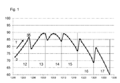
- the system for two PV modules in series with directly connected battery which consists of Akkuzellmodulen as batteries in the battery assembly according to the invention, constructed and exposed to a 1000 W solar irradiation and a 500 W solar radiation.
- the battery consists of a series of battery cells.
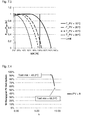
- Fig.1 and 2 each show the system efficiencies of the aforementioned embodiment in charging circuit without DC / DC switching converter.
- a variation of the number of Li-ion cells for two PV modules at a radiation of 1000 W / m 2 ( Fig.1 ) and 500 W / m 2 ( Fig.2 ) (cyclic Sunshine, a sine half-period 12 h) made. It is the system efficiency of a system consisting of a PV system with two PV modules and a battery with 12 to 17 Li-ion battery cells connected in series.
- the PV system and the battery are direct, ie via a direct electrical conductor without intermediate electronic components (except switches, relays).
- the system efficiency is also indicated for each battery cell number for different temperatures T (ambient temperatures), for 0.5, 10, 15, 20, 25, 30 and 35 ° C.
- T ambient temperatures
- the extreme values 0 and 35 ° C are labeled, while the intermediate temperatures are given in the above order with crosses on the curve.
- the cell capacity per battery cell was 50 Ah
- the SOC start value was 0% (complete discharge).
- the ratio of battery voltage to serial PV open-circuit voltage in the range of 0.5-1.5 V, is preferably between 0.5 and 0.85 V.
- a predetermined charging process advantageously has at least one charging pulse.
- a charging pulse is a time-limited time-dependent current waveform and / or voltage curve, so when the sun is shining or the radiation is obscured, for example by clouds, a charging order in sequence may also have individual pulses.
- a charge pulse is to be understood as a time-limited supply or removal of an amount of energy.
- the supplied or removed electrical power can be variable over time.
- the constant voltage phase of the current memory are resolved by these charging pulses and balanced by charging pulse, the individual accumulators. This is done via the battery management system of the power storage, which balances the cell or battery, by enabling this or the balancing device.
- a calendar life extension (based on time-dependent aging) of the accumulator by reducing the heating by excessive loads and states of charge, life extension of the accumulator by definition limit SOC min / max as the connection and disconnection criterion achievable.
- the life extension is cyclic and calendar, also by avoidance of sun / no solar current (solar flicker cycles) in high state of charge, e.g. in the constant voltage phase.
- a memory effect in the current memory is restricted or avoided if the current memories are partially charged pulsed over their operating range in a special charging process.
- Charging rate C is the charging or discharging current related to the capacity of the battery. As a result, early aging or even damage to the accumulator is reliably counteracted.
- the aim of this study is to show that a combination of photovoltaic generator and lithium-ion battery as a battery-electric storage system (BESS) can be operated safely and with acceptable efficiency without a DC / DC converter connected in front of the battery.
- the voltage level of the system is set by a BESS according to the SOC (State of charge of the battery in%). Only one relay is required between the battery and the PV generator to protect the battery from overvoltage.
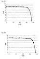
- Fig.2.2 shows the approximated IV waveform of MODULE 1.
- Fig.2.3 shows the IV curve at different temperatures.
- Fig.2 , 4 shows the PV curve at different temperatures.
- the battery must not be recharged as soon as the SOC> 100%, because then the battery can be damaged.
- Figure 4 , 1 shows by way of example four possible configurations with different numbers of series-connected lithium-ion cells (c) and different number of series-connected PV modules (PV).
- U PV T ° U PV ⁇ PV ⁇ 1 + .DELTA.U T ° ⁇ T - T STC
- I PV T ° I PV ⁇ 1 + .DELTA.I T ° ⁇ T - T STC
- U PV is the voltage of a single module at 25 ° C
- PV the number of modules
- ⁇ U T ° and ⁇ I T ° the temperature coefficients of U OC or I SC according to the manufacturer's instructions
- T the temperature of the PV modules and T STC the temperature Standard test conditions (STC, 25 ° C) are.
- Formula 4.9 is of particular importance because it shows that the three parameters or variables c, PV and T are summarized in k, so that P tobatt / P MPP remains constant when k is varied , and only the SOC needs to be recalculated.
- the introduction of k is merely a simplification of the calculations.
- the efficiency of a specific PV battery Configuration can be calculated. Comparatively, we calculate the efficiency of a system with a DC / DC converter, based on manufacturer's specifications for the efficiency of the device. Two examples are presented.
- Input Parameter (Configuration A) Input parameters PV (PV module number) 1 in series c (n ° battery cells) 9 in series T ° PV module 50 ° C ⁇ DC / DC 95 %
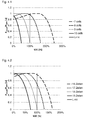
- Figure 5 , 1 shows a comparison of the efficiencies with and without DC / DC converter (configuration A).
- Figure 5 2 shows a comparison of the efficiencies with and without DC / DC converter (configuration B).
- ⁇ U represents the difference between the open circuit voltage of the PV generator and the MPP voltage of the generator.
- U OC is the open circuit voltage of a module
- U MPP is the MPP voltage of a module
- PV is the number of PV modules.
- .DELTA.U + PV ⁇ U OC - c ⁇ U cell Max
- Figure 6 1 shows the graphical representation of the security area
- Fig.6.3 gives the efficiency and a safe operating range of the PV-BESS.
- each line represents a PV battery configuration (number of cells c / PV module number) at different temperatures. It is advisable to assume that during the day the temperature of the module will vary, thus affecting the efficiency of the whole system.
- the variance of cell temperatures is set according to the maximum and minimum ambient temperatures.
- Figure 7 1 indicates the efficiency of PV-BESS for c / PV and T ° variable.
- T MIN 16.5 ° C
- T MAX 42.5 ° C.
- Q cell is the heat generated in the cell
- G is the solar radiation
- ⁇ is the efficiency of the PV module.
- QCell H ⁇ A ⁇ TCell - tamb
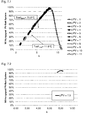
- Fig.7.3 shows P tobatt / P MPP over SOC at different temperatures.
- Figure 7 , 4 shows the course of P tobatt / P MPP over SOC at different temperatures according to a real situation.
- the system for 2 PV modules in series with directly connected battery which consists of cell modules as batteries in the battery assembly according to the invention, constructed and a 1000 W solar irradiation (see. Fig.2 ) and a 500 W solar irradiation (cf. Fig.1 ) suspended.
- Fig.1 represents the system efficiency without charge controller with a variation of the number of Li-ion cells for 2 PV modules in series at a radiation of 500 W / m 2 .
- Fig.2 represents the system efficiency without charge controller with a variation of the number of Li-ion cells for 2 PV modules in series at a radiation of 1000 W / m 2 .
- Both figures show the system efficiency of a system consisting of a PV system with 2 PV modules and a battery with 12 to 17 Li-ion cells.
- the PV system and the battery are connected together hard.
- the ratio of battery voltage to serial PV open circuit voltage is in the range of 0.5-1.5. According to a particular embodiment, this ratio is 0.5-0.85.
- a predetermined charging instruction has at least one charging pulse.
- a charging pulse is a time-limited time-dependent current waveform and / or voltage waveform. Due to solar cycles, ie when the sun is shining or the radiation is obscured by clouds, for example, a charging instruction in sequence can also have individual pulses.
- a charge pulse is to be understood as a time-limited supply or removal of an amount of energy. In this case, the supplied or removed electrical power can be variable over time.
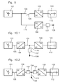
- Fig.9, 10th , 1 and 10.2 disclose exemplary interconnections of conventional electric power generators with charge controllers with switching converters for DC voltage conversion for up or down conversion of the voltage of an electrical output current of the charging circuit according to the aforementioned prior art.
- the electric power generator comprises at least one power source 101 and at least one power storage 103, wherein a charging circuit is provided and at least one power source and at least one power storage are electrically interconnected by the charging circuit via an electrical connection 104 .
- the power source is a DC source and preferably comprises one or more PV units (PV cells, PV modules, PV strings), the power storage usually accumulators (battery, battery pack, battery), ie electrochemical, physical energy storage.
- a branch 110 of the electrical connection 104 after passing through an energy measuring device 107, a forwarding to a network connection 106 (mains supply to the AC power grid).
- breaker contacts 105 are provided as switching elements for activating or deactivating individual paths.
- the power source 101 preferably formed by a battery
- disconnector 112 is also a to the battery management system connected disconnector 112 is provided, with which the respective battery off and can be switched on (optional in all described embodiments and embodiments, also in accordance with Fig. 11 ).
- Figure 9 discloses an exemplary interconnection of a conventional electric generator with charge controller with DC / DC switching converter 102 as a DC-DC converter for direct DC voltage conversion for Abw or up converting an output current of the charging circuit.
- the DC voltage generated by the current source and diverted to the grid connection portion additionally passes through a DC-AC converter 108th
- Figure 10 , 1 and 10.2 Figure 2 shows two exemplary interconnections of a conventional DC / AC AC / DC DC switching system electrical generator (each including a DC-DC converter 108 and an AC-DC converter 109) as indirect DC-DC conversion for stepping up or stepping up an output current of the charging circuit ,
- the DC voltage generated by the power source and the portion redirected to the power supply passes through the DC-AC converter 108 and an energy measuring device 107 in the connection 104 (FIG. Fig.10.1 ) or in the branch 110 ( Fig.10.2 ).
- FIG 11 an exemplary interconnection of an embodiment of an electric power generator with charge controller without DC voltage conversion for down or up conversion of an output current of the charging circuit according to the claims.
- the illustrated electrical power generator has at least one power source 101, preferably with photovoltaic cells and at least one power storage 103 , wherein a charging circuit is provided and at least one power source and at least one power storage by the charging circuit with each other are electrically connected via an electrical connection, characterized in that the charging circuit has no DC voltage conversion.
- the loading areas and the operating area are limited as described above, in particular with regard to an excellent parameter such as the temperature or the voltage at the pole terminals of the current storage 103, two parameters such as the SOC and the temperature, both in the region of the full charge and towards the empty state of charge.
- the charging circuit preferably comprises additional electrical means such as fuse elements 111, comprising preferably detection means for the temperature and / or the charging voltage and preferably at least one breaker contact for the preferably direct electrical connection between the power source and power storage without a charging electronics (eg DC voltage conversion).
- additional electrical means such as fuse elements 111, comprising preferably detection means for the temperature and / or the charging voltage and preferably at least one breaker contact for the preferably direct electrical connection between the power source and power storage without a charging electronics (eg DC voltage conversion).
Landscapes
- Engineering & Computer Science (AREA)
- Manufacturing & Machinery (AREA)
- Chemical & Material Sciences (AREA)
- Chemical Kinetics & Catalysis (AREA)
- Electrochemistry (AREA)
- General Chemical & Material Sciences (AREA)
- Power Engineering (AREA)
- Secondary Cells (AREA)
- Charge And Discharge Circuits For Batteries Or The Like (AREA)
Applications Claiming Priority (1)
| Application Number | Priority Date | Filing Date | Title |
|---|---|---|---|
| DE102013105636.9A DE102013105636A1 (de) | 2013-05-31 | 2013-05-31 | Elektrischer Stromerzeuger mit Stromspeicher und Verfahren zum Betreiben desselben |
Publications (1)
| Publication Number | Publication Date |
|---|---|
| EP2808935A1 true EP2808935A1 (fr) | 2014-12-03 |
Family
ID=50972619
Family Applications (1)
| Application Number | Title | Priority Date | Filing Date |
|---|---|---|---|
| EP14401067.5A Withdrawn EP2808935A1 (fr) | 2013-05-31 | 2014-05-28 | Générateur électrique de courant doté d'un accumulateur de courant et son procédé de fonctionnement |
Country Status (2)
| Country | Link |
|---|---|
| EP (1) | EP2808935A1 (fr) |
| DE (1) | DE102013105636A1 (fr) |
Cited By (4)
| Publication number | Priority date | Publication date | Assignee | Title |
|---|---|---|---|---|
| WO2017001030A1 (fr) * | 2015-06-29 | 2017-01-05 | Karlsruher Institut für Technologie | Système de gestion d'énergie pour un système de production d'énergie |
| DE102019220134A1 (de) * | 2019-12-19 | 2021-06-24 | Robert Bosch Gmbh | Solarsystem zum Laden von Lithium-Ionen-Akkumulatoren |
| EP4435992A4 (fr) * | 2022-03-01 | 2025-01-22 | Contemporary Amperex Technology (Hong Kong) Limited | Circuit de commande couplé à un courant continu de stockage d'énergie lumineuse et dispositif associé |
| CN119891294A (zh) * | 2025-01-15 | 2025-04-25 | 西安热工研究院有限公司 | 适应于储能发电机组的高排温度控制方法及系统 |
Families Citing this family (1)
| Publication number | Priority date | Publication date | Assignee | Title |
|---|---|---|---|---|
| DE102024200994A1 (de) * | 2024-02-02 | 2025-08-07 | Forschungszentrum Jülich GmbH | Batterie mit Überladeschutz, System und Verwendung |
Citations (4)
| Publication number | Priority date | Publication date | Assignee | Title |
|---|---|---|---|---|
| US20090302681A1 (en) * | 2006-01-27 | 2009-12-10 | Kazuo Yamada | Power supply system |
| US20120047386A1 (en) * | 2009-04-30 | 2012-02-23 | Ryoji Matsui | Control apparatus and control method |
| US20120176079A1 (en) * | 2009-10-29 | 2012-07-12 | Sanyo Electric Co., Ltd. | Switching Circuit, Control Apparatus, and Power Generation System |
| DE102011115032A1 (de) | 2011-03-19 | 2012-09-20 | Neutron Mikroelektronik Gmbh | Ladeschaltung für einen Akkuzellensatz |
-
2013
- 2013-05-31 DE DE102013105636.9A patent/DE102013105636A1/de not_active Withdrawn
-
2014
- 2014-05-28 EP EP14401067.5A patent/EP2808935A1/fr not_active Withdrawn
Patent Citations (4)
| Publication number | Priority date | Publication date | Assignee | Title |
|---|---|---|---|---|
| US20090302681A1 (en) * | 2006-01-27 | 2009-12-10 | Kazuo Yamada | Power supply system |
| US20120047386A1 (en) * | 2009-04-30 | 2012-02-23 | Ryoji Matsui | Control apparatus and control method |
| US20120176079A1 (en) * | 2009-10-29 | 2012-07-12 | Sanyo Electric Co., Ltd. | Switching Circuit, Control Apparatus, and Power Generation System |
| DE102011115032A1 (de) | 2011-03-19 | 2012-09-20 | Neutron Mikroelektronik Gmbh | Ladeschaltung für einen Akkuzellensatz |
Non-Patent Citations (4)
| Title |
|---|
| ANONYMOUS: "Solar-Batterieschutz - PRIUSforum", 17 June 2009 (2009-06-17), XP055484521, Retrieved from the Internet <URL:https://www.priusfreunde.de/portal/index.php?option=com_kunena&Itemid=117&func=view&catid=43&id=51974&limit=1&limitstart=33#81644> [retrieved on 20180614] * |
| ANONYMOUS: "Solar-Batterieschutz - PRIUSforum", 18 June 2009 (2009-06-18), XP055484528, Retrieved from the Internet <URL:https://www.priusfreunde.de/portal/index.php?option=com_kunena&Itemid=117&func=view&catid=43&id=51974&limit=1&limitstart=38> [retrieved on 20180614] * |
| HEINRICH HÄBERLEIN: "Photovoltaik Strom aus Sonnenlicht für Verbundnetz und Inselanlagen", 2007, pages: 130 |
| VOLTWERK; BOSCH GRUPPE, GEGEN DEN STROM, MIT DER INTELLIGENTEN SPEICHERLÖSUNG VS 5 HYBRID, 13 June 2013 (2013-06-13) |
Cited By (4)
| Publication number | Priority date | Publication date | Assignee | Title |
|---|---|---|---|---|
| WO2017001030A1 (fr) * | 2015-06-29 | 2017-01-05 | Karlsruher Institut für Technologie | Système de gestion d'énergie pour un système de production d'énergie |
| DE102019220134A1 (de) * | 2019-12-19 | 2021-06-24 | Robert Bosch Gmbh | Solarsystem zum Laden von Lithium-Ionen-Akkumulatoren |
| EP4435992A4 (fr) * | 2022-03-01 | 2025-01-22 | Contemporary Amperex Technology (Hong Kong) Limited | Circuit de commande couplé à un courant continu de stockage d'énergie lumineuse et dispositif associé |
| CN119891294A (zh) * | 2025-01-15 | 2025-04-25 | 西安热工研究院有限公司 | 适应于储能发电机组的高排温度控制方法及系统 |
Also Published As
| Publication number | Publication date |
|---|---|
| DE102013105636A1 (de) | 2014-12-04 |
Similar Documents
| Publication | Publication Date | Title |
|---|---|---|
| EP3014736B1 (fr) | Procédé et dispositif de stockage d'énergie électrique dans des accumulateurs d'énergie électrochimiques | |
| CN114465291B (zh) | 基于能源云互联的大型分布式柔性风光储充放市电交直流混用系统及控制系统 | |
| Hund et al. | Grid-tied PV system energy smoothing | |
| Subburaj et al. | Overview of grid connected renewable energy based battery projects in USA | |
| US8633671B2 (en) | Photo-voltaic charging of high voltage traction batteries | |
| EP2688171B1 (fr) | Accumulateur d'énergie pour installation photovoltaïque, centrale d'accumulation d'énergie, appareil de commande et procédé de fonctionnement d'un accumulateur d'énergie | |
| DE102014102352A1 (de) | Batteriespeichersystem mit Störlichtbogenschutz, Energieumwandlungssystem und Schutzverfahren | |
| KR20130138611A (ko) | 에너지 저장 시스템 | |
| DE112015001198T5 (de) | Energieversorgungssystem | |
| Chatrung | Battery energy storage system (BESS) and development of grid scale BESS in EGAT | |
| EP2808935A1 (fr) | Générateur électrique de courant doté d'un accumulateur de courant et son procédé de fonctionnement | |
| DE102013107767A1 (de) | Mehrzellige Batterie mit Zellladungszustandsausgleich | |
| Betzin et al. | Electrical operation behavior and energy efficiency of battery systems in a virtual storage power plant for primary control reserve | |
| EP3844465B1 (fr) | Dispositif photovoltaïque à vieillissement réduit | |
| EP1332539B1 (fr) | Dispositif chargeur de batteries et procede permettant de charger des batteries a plusieurs blocs de batteries | |
| Jafari et al. | Technical issues of sizing lead-acid batteries for application in residential renewable energy systems | |
| WO2014095343A2 (fr) | Procédé de fonctionnement d'accumulateurs d'énergie | |
| Khouzam | The load matching approach to sizing photovoltaic systems with short-term energy storage | |
| Bolufawi | Renewable energy integration with energy storage systems and safety | |
| Berseneff et al. | The significance of energy storage for renewable energy generation and the role of instrumentation and measurement | |
| Jusoh et al. | Fuzzy logic-based control strategy for hourly power dispatch of grid-connected photovoltaic with hybrid energy storage | |
| WO2009109251A1 (fr) | Unité d'accumulation d'énergie électrique indépendante du réseau | |
| Pichetjamroen et al. | A Study on performances of flexible power control with empirical lithium-ion battery modeling in PV power systems | |
| DE102015007405A1 (de) | Energiespeichersystem | |
| WO2014180839A1 (fr) | Procédé de fourniture de puissance de réglage à un réseau électrique au moyen d'un accumulateur |
Legal Events
| Date | Code | Title | Description |
|---|---|---|---|
| PUAI | Public reference made under article 153(3) epc to a published international application that has entered the european phase |
Free format text: ORIGINAL CODE: 0009012 |
|
| 17P | Request for examination filed |
Effective date: 20140528 |
|
| AK | Designated contracting states |
Kind code of ref document: A1 Designated state(s): AL AT BE BG CH CY CZ DE DK EE ES FI FR GB GR HR HU IE IS IT LI LT LU LV MC MK MT NL NO PL PT RO RS SE SI SK SM TR |
|
| AX | Request for extension of the european patent |
Extension state: BA ME |
|
| R17P | Request for examination filed (corrected) |
Effective date: 20150910 |
|
| RBV | Designated contracting states (corrected) |
Designated state(s): AL AT BE BG CH CY CZ DE DK EE ES FI FR GB GR HR HU IE IS IT LI LT LU LV MC MK MT NL NO PL PT RO RS SE SI SK SM TR |
|
| 17Q | First examination report despatched |
Effective date: 20170720 |
|
| STAA | Information on the status of an ep patent application or granted ep patent |
Free format text: STATUS: THE APPLICATION IS DEEMED TO BE WITHDRAWN |
|
| 18D | Application deemed to be withdrawn |
Effective date: 20190103 |