EP2808964B1 - System, das als waagrechte Halterung für einen Gegenstand wie einen Kabelkanal dienen soll, und Schiene für ein solches System - Google Patents
System, das als waagrechte Halterung für einen Gegenstand wie einen Kabelkanal dienen soll, und Schiene für ein solches System Download PDFInfo
- Publication number
- EP2808964B1 EP2808964B1 EP14169720.1A EP14169720A EP2808964B1 EP 2808964 B1 EP2808964 B1 EP 2808964B1 EP 14169720 A EP14169720 A EP 14169720A EP 2808964 B1 EP2808964 B1 EP 2808964B1
- Authority
- EP
- European Patent Office
- Prior art keywords
- rail
- wall
- apertures
- male fastening
- concave curved
- Prior art date
- Legal status (The legal status is an assumption and is not a legal conclusion. Google has not performed a legal analysis and makes no representation as to the accuracy of the status listed.)
- Active
Links
Images

Classifications
-
- H—ELECTRICITY
- H02—GENERATION; CONVERSION OR DISTRIBUTION OF ELECTRIC POWER
- H02G—INSTALLATION OF ELECTRIC CABLES OR LINES, OR OF COMBINED OPTICAL AND ELECTRIC CABLES OR LINES
- H02G3/00—Installations of electric cables or lines or protective tubing therefor in or on buildings, equivalent structures or vehicles
- H02G3/30—Installations of cables or lines on walls, floors or ceilings
- H02G3/34—Installations of cables or lines on walls, floors or ceilings using separate protective tubing
-
- H—ELECTRICITY
- H02—GENERATION; CONVERSION OR DISTRIBUTION OF ELECTRIC POWER
- H02G—INSTALLATION OF ELECTRIC CABLES OR LINES, OR OF COMBINED OPTICAL AND ELECTRIC CABLES OR LINES
- H02G3/00—Installations of electric cables or lines or protective tubing therefor in or on buildings, equivalent structures or vehicles
- H02G3/02—Details
- H02G3/04—Protective tubing or conduits, e.g. cable ladders or cable troughs
- H02G3/0406—Details thereof
-
- H—ELECTRICITY
- H02—GENERATION; CONVERSION OR DISTRIBUTION OF ELECTRIC POWER
- H02G—INSTALLATION OF ELECTRIC CABLES OR LINES, OR OF COMBINED OPTICAL AND ELECTRIC CABLES OR LINES
- H02G3/00—Installations of electric cables or lines or protective tubing therefor in or on buildings, equivalent structures or vehicles
- H02G3/02—Details
- H02G3/04—Protective tubing or conduits, e.g. cable ladders or cable troughs
- H02G3/0425—Plinths
-
- H—ELECTRICITY
- H02—GENERATION; CONVERSION OR DISTRIBUTION OF ELECTRIC POWER
- H02G—INSTALLATION OF ELECTRIC CABLES OR LINES, OR OF COMBINED OPTICAL AND ELECTRIC CABLES OR LINES
- H02G3/00—Installations of electric cables or lines or protective tubing therefor in or on buildings, equivalent structures or vehicles
- H02G3/02—Details
- H02G3/04—Protective tubing or conduits, e.g. cable ladders or cable troughs
- H02G3/0456—Ladders or other supports
Definitions
- the invention relates to carrier elements for providing support for an object such as a cable tray.
- the carrier rail has at least one wall having a series of openings disposed along the rail in a regular pitch, each opening being configured to receive a male fastener of the console.
- the openings have a circular contour and the male fasteners have a circular section body.
- the male fastening member is a screw
- the openings of the rail have a rectangular outline, the male fasteners being claws having a bearing surface on the underside of the opening, which is flat.
- the French patent application 2,812,927 is described in particular by the French patent application 2,812,927 .
- the invention aims to provide systems of the same kind, but more convenient and more economical.
- the bearing surface of this member is in contact with the concave curved segment of the first side and the concave curved segment of the second side.
- neither the first male fastener nor the second male fastener member cooperates with the periphery of the openings in the same way only with the circular openings or with the rectangular openings of the previous supporting rails.
- the contact is made on the entire periphery of the opening; and in the anterior carrier rail with rectangular openings, the contact is made on the entire bearing surface of the male fastener member.
- the system according to the invention is much more convenient and economical than the two prior conventional systems each comprising a carrier rail and a console specific to each other. 'other.
- the invention also aims, in a second aspect, a carrier rail suitable for the system as described above, having a wall having a series of openings disposed along said rail at a regular pitch, each said opening being configured to receiving a male fastener member of a bracket having a bearing surface on the periphery of the opening of the rail, which is circular section of predetermined diameter; characterized in that each said opening of said rail has a contour having a first side and a second side each oriented transverse to the general direction of the rail, the first side and the second side facing each other and comprising each a concave curved segment and two segments disposed on either side of the concave curved segment, the concave curved segment of the first side and the concave curved segment of the second side each following an arc of the same circle having said predetermined diameter, the segments of the first side disposed on either side of the concave curved segment being straight and aligned, whereby each said opening of the rail can receive both a first male fastening member having a bearing
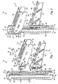
- the system 10 shown on the Figures 1 to 4 comprises a carrier rail 11, a first console 12 and a second console 13.
- the carrier rail 11 is a profiled metal element, here in U-shaped section, having a bottom 14 and two lateral wings 15 each connected by a longitudinal side to a respective longitudinal side of the bottom 14.
- the lateral wings 15 are opposite one another and each have a conformation which is the mirror image of the conformation of the other lateral wing 15.
- each lateral flange 15 has a side wall 16 and an L-shaped return 17 having a flange 18 and a flanged edge 19.
- the carrier rail 11 is provided to be fixed vertically on a structure such as a wall.
- the bottom 14 has openings for the passage of a fastener such as a screw. To simplify the drawings, the openings in the bottom 14 are not illustrated.
- Each side wall 16 has a series of openings 20 arranged along the rail 11 in a regular pitch.
- the openings 20 all have the same outline, which will be described later in detail in support of the figure 5 .
- Each opening 20 of a lateral flange 15 is aligned with an opening 20 of the other lateral flange 15 in a direction transverse to the general orientation of the rail 11, here a direction parallel to the bottom 14 and transverse to the side walls 16.
- Each of the openings 20 is configured to receive both a male fastener of the first bracket 12 and a male fastener of the second bracket 13.
- the first console 12 has a portion configured to form a horizontal support for an object such as a cable tray when it is fixed to the carrier rail 11 itself fixed vertically on a structure such as a wall. The same goes for the second console 13.
- the portion for providing horizontal support to an object such as a cable tray is a generally rectangular support wall 25.
- the first bracket 12 comprises two lateral wings 26 each connected by a longitudinal side to a respective longitudinal side of the support wall 25.
- the lateral wings 26 are facing each other and each have a conformation which is the mirror image of the conformation of the other lateral wing 26.
- each lateral wing 26 comprises a cheek 27 and a flange 28.
- Each flange 28 has two openings 30 each having a circular contour of the same predetermined diameter.
- Each opening 30 of a flange 28 is aligned with an opening 30 of the other flange 28 in a direction transverse to the general orientation of the first bracket 12, here a direction parallel to the support wall 25 and transverse to the flanges 28 .
- the distance between the two openings 30 of each flange 28 is a multiple of the pitch between the openings 20 of the rail 11.
- the distance between the two openings 30 of each flange 28 is three times the pitch of the series of openings 20.
- the gap between the inner faces of the flanges 28 corresponds to the distance between the external faces of the side walls 16.
- the carrier rail 11 and the first bracket 12 are configured so that the rail 11 can engage between the flanges 28 with the inner face of each flange 28 which faces the outer face of a respective side wall 16 of the carrier rail 11, the returns 17 being on the side of the support wall 25, as shown in particular on the figure 2 .
- the openings 30 in the tongues 29 are aligned with the two highest openings 20 of the carrier rail 11 while the other two openings 30 are aligned with the third opening 20 from the highest opening.
- the system 10 comprises two pins 31. On the figure 1 to simplify the drawing, a single pin 31 is illustrated.
- Each pin 31 comprises a body 32 and a head 33.
- the body 32 is cylindrical and of the same predetermined diameter as the openings 30.
- the head 33 is in overflow of the body 32.
- the system 10 comprises a locking ring 34 having an internal toothing shaped to allow sliding along the body 32 of the pin 31 in a single direction, so that once positioned as shown on the figures 2 and 3 , the ring 34 remains in place.
- Elongate openings 35 are provided in the wall 25 to allow attachment of the object such as a cable tray.
- the portion for providing horizontal support for an object such as a cable tray is formed by a support wall 40 and notches 41 formed in the support wall 40 and in the junction zone between the support wall 40 and a cheek 42 of the second bracket 13.
- the object to be supported is placed on the wall 40, for example if it is a perforated sheet metal cable tray, or engaged in the notches 41, for example if it is a cable tray made of metal wire.
- the support wall 40 has elongated openings 43 to allow attachment of the object to be supported.
- the second bracket 13 comprises a flange 44 and a bottom 45 ( figure 3 ).
- the cheek 42 is disposed transversely to the support wall 40 and extends over the entire length of the support wall 40.
- the side of the cheek 42 which is opposite to the support wall 40 is inclined.
- the rim 44 is disposed transversely to the cheek 42 facing the support wall 40.
- the bottom 45 is disposed transversely to the support wall 40 and to the cheek 42 along the largest transverse side of the cheek 42, namely the side that is seen to the left on the Figures 1, 2 and 4 .
- the support wall 40, the flange 44 and the bottom 45 are arranged on the same side.
- the cheek 42 has two claws 46, a lug 47 and a tab 48 to fold.
- the claw 46 and the lug 47 protrude, with respect to the general plane of the cheek 42, from the side opposite to that where the support wall 40 is located.
- the two claws 46 are L-section with a first wall 49 oriented transversely to the general plane of the cheek 42 and a second wall 50 oriented parallel to the general plane of the cheek 52.
- Each of the claws 46 has been formed by providing a U-shaped cutout and then folding the material delimited by this cut in two folds to form respectively the first wall 49 and the second wall 50.
- the lug 47 extends transversely to the general plane of the cheek 42. It has been formed by a cut and then by a fold to orient it transversely to the general plane of the cheek 42, parallel to the first wall 49 of the claws 46.
- Folding tab 48 extends along the general plane of cheek 2. It is delimited by a U-shaped cutout. The side by which fold tab 48 is attached to the remainder of cheek 42 is oriented in the transverse direction of the cheek 42.
- the distance between the two claws 46 is a multiple of the pitch between the openings 20 of the rail 11.
- the distance between the two claws 46 is twice the pitch of the series of openings 20.
- the second bracket 13 and the carrier rail 11 are configured to be fixed to each other with the face of the cheek 42 which protrude the claws 46 which is against the outer face of the side wall 16 of one of the wings 15, with each of the claws 46 which is engaged in an opening 20, as shown on the Figures 2 to 4 .
- each claw 46 passes through an opening 20 and the second wall 50 of each claw 46 is opposite the internal face of the side wall 16 of the wing 15 against which is disposed the second console 13.
- the folding tab 48 is then at the right of the opening 20 which is between the two openings 20 receiving a claw 46 while the lug 47 is engaged in the opening 20 located under the lower claw 46.
- the tab 48 is folded to engage the opening 20 to the right of which it is located.
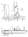
- the openings 20 of the carrier rail 11 all have the same contour, which will now be described in support of the figure 5 .
- each opening 20 has a first side 51 and a second side 52 each oriented transverse to the general direction of the rail 11, the first side 51 and the second side 52 facing each other.
- each opening 20 also has a third side 53 and a fourth side 54 each oriented in the general direction of the rail 11, the third side and the fourth side facing each other.
- each opening 20 has a four-sided contour 51 to 54, the third side 53 extending between one end of the first side 51 and one end of the second side 52 while the fourth side 54 extends between the other end the first side 51 and the other end of the second side 52.
- the first side 51 and the second side 52 each comprise a segment 55 which is curved concave and two segments 56 and 57 which are arranged on either side of the segment 55.
- the segment 55 of the first side 51 and the segment 55 of the second side 52 each follow an arc of the same circle whose diameter is the same as that of the openings 30 of the first bracket 12 and the body 32 of the pins 31.
- the segments 56 and 57 of the first side 51 are straight and aligned.
- the segments 56 and 57 of the second side 52 are also straight and aligned.
- the surface 60 of the body 32 forms a bearing surface on the periphery of an opening 20 of the rail 11.
- the surface 60 is in contact with the periphery of the opening 20 by the segment 55 of the first side 51 and by the segment 55 of the second side 52.
- the surface 61 of the first wall 49 located on the side of the second wall 50 forms a bearing surface on the periphery of the opening 20.
- the surface 61 is flat.
- the first side 51 of the opening 20 has a length slightly larger than the length of the surface 61 of the claws 46, which corresponds to the width of the claws 46.
- each opening 20 of the carrier rail 11 can receive both a male fastener member of the first bracket 12, that is to say a pin 31, a male fastener member of the second bracket 13, c ' that is, a claw 46.
- brackets whose fixing member is a pin is provided a first carrier rail whose openings have a circular contour and there is provided a second rail whose openings have a rectangular contour for the consoles of which the male fastener is a claw.
- the lug 47 of the second bracket 13 cooperates with the periphery of the opening 20 in which it is arranged exactly in the same way as the first wall 49 of the claws 46.
- the two pins 31 are spaced, like the openings 30, a multiple n of the pitch between the openings 20; and it is recalled that in the second bracket 13, the claws 46 are spaced from each other by a multiple m of the pitch between the openings 20; with here the multiple n which is different from the multiple m (in the example illustrated, the multiple n is equal to 3 and the multiple m is equal to 2).
- system 10 shown on the Figures 1 to 4 illustrates the ability of the rail 11 to cooperate with both a first console 12 with a second console 13; and that of course in practice the rail 11 is usable with only first consoles 12 or only second consoles 13.
- the carrier rail 11 illustrated on Figures 8 and 9 is identical to the carrier rail 11 illustrated on the Figures 1 to 4 except that the edge of the dropped edge 19 of each return 17 is notched; and that each sidewall 16 has a slight recess at the series of openings 20.
- each side wall 16 has an inclined portion 65 at the segments 56 and 57 of the perimeter of the openings 20 and a portion 66 parallel to the general plane of the side wall 16 at the concave curved segments 55 of the periphery of the openings 20, with each portion 65 which is inclined towards the portion 66 and towards the inside of the carrier rail 11.
Landscapes
- Engineering & Computer Science (AREA)
- Architecture (AREA)
- Civil Engineering (AREA)
- Structural Engineering (AREA)
- Drawers Of Furniture (AREA)
- Bearings For Parts Moving Linearly (AREA)
- Vehicle Step Arrangements And Article Storage (AREA)
Claims (10)
- System zum Bereitstellen einer horizontalen Auflage für einen Gegenstand wie etwa eine Kabelwanne, mit einer Tragschiene (11) und einem Träger, der ein Stück aufweist, das zum Bilden der horizontalen Auflage ausgebildet ist, wenn er an der Tragschiene (11) befestigt ist, die ihrerseits vertikal an einer Struktur wie etwa einer Mauer befestigt ist, wobei die Tragschiene eine Wand (16) mit einer Reihe von Öffnungen (20) aufweist, die entlang der Schiene (11) in gleichmäßigem Abstand angeordnet sind, wobei jede Öffnung (20) zur Aufnahme eines Befestigungssteckelements des Trägers ausgebildet ist, das eine Fläche (60) zur Auflage am Umfangsrand der Öffnung (20) der Schiene (11) aufweist, die einen runden Querschnitt mit vorbestimmtem Durchmesser hat,
dadurch gekennzeichnet, dass- das System (10) Befestigungssteckelemente (31), nachstehend als erste Befestigungssteckelemente (31) bezeichnet, für erste Träger (12) und zweite Befestigungssteckelemente (46) für zweite Träger (13) umfasst;- jedes zweite Befestigungssteckelement (46) eine Fläche (61) zur Auflage am Umfangsrand der Öffnung (20) der Schiene (11) aufweist, die eben mit vorbestimmter Länge ist; und- jede Öffnung (20) der Schiene (11) einen Umriss mit einer ersten Seite (51) und einer zweiten Seite (52) aufweist, die jeweils quer zur allgemeinen Richtung der Schiene (11) ausgerichtet sind, wobei die erste Seite (51) und die zweite Seite (52) einander gegenüberliegend angeordnet sind und jeweils ein konkav gebogenes Segment (55) und zwei beidseits des konkav gebogenen Segments (55) angeordnete Segmente (56, 57) aufweisen, wobei das konkav gebogene Segment (55) der ersten Seite (51) und das konkav gebogene Segment (55) der zweiten Seite (52) jeweils einem Bogen ein und desselben Kreises folgen, der den vorbestimmten Durchmesser aufweist, wobei die beidseits des konkav gebogenen Segments (55) angeordneten Segmente (56, 57) der erste Seite (51) gerade und fluchtend ausgerichtet sind, wobei die erste Seite (51) eine Länge aufweist, die wenigstens der vorbestimmten Länge entspricht, wodurch jede Öffnung (20) der Schiene (11) sowohl ein erstes Befestigungssteckelement (31) als auch ein zweites Befestigungssteckelement (46) aufnehmen kann. - System nach Anspruch 1,
dadurch gekennzeichnet, dass jede Öffnung (20) auch eine dritte Seite (53) und eine vierte Seite (54) aufweist, die jeweils in der allgemeinen Richtung der Schiene (11) ausgerichtet sind, wobei die dritte Seite (53) und die vierte Seite (54) einander gegenüberliegend angeordnet sind, wobei die dritte Seite (53) zwischen einem Ende der ersten Seite (51) und einem Ende der zweiten Seite (52) verläuft und wobei die vierte Seite (54) zwischen dem anderen Ende der ersten Seite (51) und dem anderen Ende der zweiten Seite (52) verläuft. - System nach einem der Ansprüche 1 oder 2,
dadurch gekennzeichnet, dass die zwei beidseits des konkav gebogenen Segments (55) angeordneten Segmente (56, 57) auf der zweiten Seite (52) gerade und fluchtend ausgerichtet sind. - System nach einem der Ansprüche 1 bis 3,
dadurch gekennzeichnet, dass es für jeden ersten Träger (12) zwei erste Befestigungssteckelemente (31) umfasst, die um ein Vielfaches n des Abstands zwischen den Öffnungen (20) der Schiene (11) beabstandet sind, während es für jeden zweiten Träger (13) zwei Befestigungssteckelemente (43) umfasst, die voneinander um ein Vielfaches m des Abstands zwischen den Öffnungen (20) der Tragschiene (11) beabstandet sind, wobei sich das Vielfache n von dem Vielfachen m unterscheidet. - System nach Anspruch 4,
dadurch gekennzeichnet, dass das Vielfache n gleich 3 ist und das Vielfache m gleich 2 ist. - System nach einem der Ansprüche 1 bis 5,
dadurch gekennzeichnet, dass der erste Träger (12) zwei Seitenteile (28) aufweist, die jeweils mit einer Öffnung (30) zur Aufnahme eines ersten Befestigungssteckelements (31) versehen sind, wobei die Tragschiene (11) und der Träger (12) so ausgebildet sind, dass die Tragschiene (11) zwischen die Seitenteile (28) eingeführt werden kann und jede Öffnung (30) eines jeden Seitenteils (28) mit einer Öffnung (20) der Tragschiene (11) fluchtend ausgerichtet ist. - System nach einem der Ansprüche 1 bis 6,
dadurch gekennzeichnet, dass der zweite Träger (13) zwei zweite Befestigungssteckelemente (46) aufweist, die einen L-förmigen Querschnitt mit einer ersten Wand (49) und einer zweiten Wand (50) haben, die zueinander quer verlaufend angeordnet sind, wobei die Auflagefläche (61) durch die Fläche der auf der Seite der zweiten Wand (50) gelegenen ersten Wand (49) gebildet ist, wobei der zweite Träger (13) und die Tragschiene (11) so ausgebildet sind, dass sie aneinander befestigt werden, wobei die erste Wand (49) durch eine Öffnung (20) der Tragschiene (11) hindurch verläuft und die zweite Wand (50) der Innenseite der mit den Öffnungen (20) versehenen Wand (16) der Tragschiene (11) gegenüberliegt. - Tragschiene mit einer Wand (16), die eine Reihe von Öffnungen (20) aufweist, die entlang der Schiene (11) in gleichmäßigem Abstand angeordnet sind, wobei jede Öffnung (20) zur Aufnahme eines Befestigungssteckelements eines Trägers ausgebildet ist, das eine Fläche (60) zur Auflage am Umfangsrand der Öffnung (20) der Schiene (11) aufweist, die einen runden Querschnitt mit vorbestimmtem Durchmesser hat,
dadurch gekennzeichnet, dass jede Öffnung (20) der Schiene (11) einen Umriss mit einer ersten Seite (51) und einer zweiten Seite (52) aufweist, die jeweils quer zur allgemeinen Richtung der Schiene ausgerichtet sind, wobei die erste Seite (51) und die zweite Seite (52) einander gegenüberliegend angeordnet sind und jeweils ein konkav gebogenes Segment (55) und zwei beidseits des konkav gebogenen Segments (55) angeordnete Segmente (56, 57) aufweisen, wobei das konkav gebogene Segment (55) der ersten Seite (51) und das konkav gebogene Segment (55) der zweiten Seite (52) jeweils einem Bogen ein und desselben Kreises folgen, der den vorbestimmten Durchmesser aufweist, wobei die beidseits des konkav gebogenen Segments (55) angeordneten Segmente (56, 57) der ersten Seite (51) gerade und fluchtend ausgerichtet sind, wodurch jede Öffnung (20) der Schiene (11) sowohl ein erstes Befestigungssteckelement (31), das eine Fläche (60) zur Auflage am Umfangsrand der Öffnung (20) der Schiene (11) aufweist, die einen runden Querschnitt mit dem vorbestimmten Durchmesser hat, als auch ein zweites Befestigungssteckelement (46), das eine Fläche (61) zur Auflage am Umfangsrand der Öffnung (20) der Schiene (11) aufweist, die eben ist, aufnehmen kann. - Tragschiene nach Anspruch 8,
dadurch gekennzeichnet, dass sie zwei Wände (16) mit einer Reihe Öffnungen (20) umfasst, wobei jede Öffnung (20) der einen Wand (16) mit einer Öffnung (20) der anderen Wand (16) fluchtend ausgerichtet ist. - Tragschiene nach Anspruch 9,
dadurch gekennzeichnet, dass sie durch ein Metallprofil mit U-förmigem Querschnitt gebildet ist, das einen Boden (14) und die beiden Wände (16) umfasst, die jeweils durch eine Längsseite mit einer entsprechenden Längsseite des Bodens (14) verbunden sind.
Applications Claiming Priority (1)
| Application Number | Priority Date | Filing Date | Title |
|---|---|---|---|
| FR1354987A FR3006511B1 (fr) | 2013-05-31 | 2013-05-31 | Systeme pour fournir un support horizontal a un objet tel qu'un chemin de cables et rail pour un tel systeme |
Publications (2)
| Publication Number | Publication Date |
|---|---|
| EP2808964A1 EP2808964A1 (de) | 2014-12-03 |
| EP2808964B1 true EP2808964B1 (de) | 2015-11-04 |
Family
ID=48874370
Family Applications (1)
| Application Number | Title | Priority Date | Filing Date |
|---|---|---|---|
| EP14169720.1A Active EP2808964B1 (de) | 2013-05-31 | 2014-05-23 | System, das als waagrechte Halterung für einen Gegenstand wie einen Kabelkanal dienen soll, und Schiene für ein solches System |
Country Status (4)
| Country | Link |
|---|---|
| EP (1) | EP2808964B1 (de) |
| CN (1) | CN104214435B (de) |
| ES (1) | ES2561129T3 (de) |
| FR (1) | FR3006511B1 (de) |
Cited By (7)
| Publication number | Priority date | Publication date | Assignee | Title |
|---|---|---|---|---|
| DE202021104125U1 (de) | 2021-08-03 | 2022-11-04 | OBO Bettermann Produktion Deutschland GmbH & Co. KG | Baugruppe eines Kabeltragsystems |
| DE202021104126U1 (de) | 2021-08-03 | 2022-11-07 | OBO Bettermann Produktion Deutschland GmbH & Co. KG | Endseitig einseitig abgestützter Ausleger für ein Kabeltragsystem |
| DE202021104122U1 (de) | 2021-08-03 | 2022-11-07 | OBO Bettermann Hungary Kft. | Kopfanschlussteil zum Befestigen eines Hängestiels eines Kabeltragsystems an einer Decke |
| DE102021120323A1 (de) | 2021-08-04 | 2023-02-09 | OBO Bettermann Produktion Deutschland GmbH & Co. KG | Endseitig einseitig abgestützter Ausleger für ein Kabeltragsystem |
| US11662041B2 (en) | 2019-07-29 | 2023-05-30 | Erico International Corporation | Support clip |
| EP4277061A1 (de) | 2022-05-11 | 2023-11-15 | OBO Bettermann Produktion Deutschland GmbH & Co.KG | Kabeltragsystem sowie tragvorrichtung dafür |
| DE102022111942A1 (de) | 2022-05-12 | 2023-11-16 | OBO Bettermann Produktion Deutschland GmbH & Co. KG | Kabeltragsystem sowie Träger dafür |
Families Citing this family (4)
| Publication number | Priority date | Publication date | Assignee | Title |
|---|---|---|---|---|
| CN106641464B (zh) * | 2016-12-16 | 2018-08-07 | 中国海洋石油总公司 | 管线支架的固定工艺 |
| FR3060884B1 (fr) | 2016-12-16 | 2019-05-24 | Legrand France | Systeme comportant un rail porteur et une platine configuree pour etre fixee a un support et immobiliser le rail dispose debout sous le support |
| CN109534096A (zh) * | 2018-10-25 | 2019-03-29 | 徐州木牛流马机器人科技有限公司 | 一种防止机器连接线的缠绕装置 |
| GB2607251B (en) * | 2019-09-09 | 2023-11-15 | Gripple Ltd | Suspension assembly |
Family Cites Families (4)
| Publication number | Priority date | Publication date | Assignee | Title |
|---|---|---|---|---|
| FR2757696B1 (fr) * | 1996-12-19 | 1999-02-26 | Metal Deploye Sa | Console pour conduits porteurs |
| FR2812927B1 (fr) * | 2000-08-08 | 2002-10-31 | Krieg & Zivy Ind | Console de support d'objet, en particulier console de support de chemin de cables, notamment en treillis |
| FR2881038B1 (fr) * | 2005-01-27 | 2008-05-30 | Jacques Bailleux | Dispositif de support comportant une console |
| CN201259022Y (zh) * | 2008-09-03 | 2009-06-17 | 合肥市鹏辉电力设备有限公司 | 插拔式复合电缆支架 |
-
2013
- 2013-05-31 FR FR1354987A patent/FR3006511B1/fr not_active Expired - Fee Related
-
2014
- 2014-05-23 ES ES14169720.1T patent/ES2561129T3/es active Active
- 2014-05-23 EP EP14169720.1A patent/EP2808964B1/de active Active
- 2014-05-30 CN CN201410235012.2A patent/CN104214435B/zh active Active
Cited By (14)
| Publication number | Priority date | Publication date | Assignee | Title |
|---|---|---|---|---|
| US11662041B2 (en) | 2019-07-29 | 2023-05-30 | Erico International Corporation | Support clip |
| EP4145651A1 (de) | 2021-08-03 | 2023-03-08 | OBO Bettermann Produktion Deutschland GmbH & Co.KG | Endseitig einseitig abgestützter ausleger für ein kabeltragsystem |
| DE202021104122U1 (de) | 2021-08-03 | 2022-11-07 | OBO Bettermann Hungary Kft. | Kopfanschlussteil zum Befestigen eines Hängestiels eines Kabeltragsystems an einer Decke |
| EP4131682A1 (de) | 2021-08-03 | 2023-02-08 | OBO Bettermann Hungary Kft. | Kopfanschlussteil zum befestigen eines hängestiels eines kabeltragsystems an einer decke |
| EP4131683A1 (de) | 2021-08-03 | 2023-02-08 | OBO Bettermann Produktion Deutschland GmbH & Co.KG | Baugruppe eines kabeltragsystems |
| DE202021104125U1 (de) | 2021-08-03 | 2022-11-04 | OBO Bettermann Produktion Deutschland GmbH & Co. KG | Baugruppe eines Kabeltragsystems |
| DE202021104126U1 (de) | 2021-08-03 | 2022-11-07 | OBO Bettermann Produktion Deutschland GmbH & Co. KG | Endseitig einseitig abgestützter Ausleger für ein Kabeltragsystem |
| EP4145651B1 (de) * | 2021-08-03 | 2025-06-25 | OBO Bettermann Produktion Deutschland GmbH & Co.KG | Endseitig einseitig abgestützter ausleger für ein kabeltragsystem |
| DE102021120323A1 (de) | 2021-08-04 | 2023-02-09 | OBO Bettermann Produktion Deutschland GmbH & Co. KG | Endseitig einseitig abgestützter Ausleger für ein Kabeltragsystem |
| DE102021120323B4 (de) | 2021-08-04 | 2024-02-29 | OBO Bettermann Produktion Deutschland GmbH & Co. KG | Endseitig einseitig abgestützter Ausleger für ein Kabeltragsystem |
| EP4277061A1 (de) | 2022-05-11 | 2023-11-15 | OBO Bettermann Produktion Deutschland GmbH & Co.KG | Kabeltragsystem sowie tragvorrichtung dafür |
| DE202023003141U1 (de) | 2022-05-11 | 2026-04-30 | OBO Bettermann Produktion Deutschland GmbH & Co. KG | Kabeltragsystem sowie Tragvorrichtung dafür |
| DE102022111942A1 (de) | 2022-05-12 | 2023-11-16 | OBO Bettermann Produktion Deutschland GmbH & Co. KG | Kabeltragsystem sowie Träger dafür |
| DE102022111942B4 (de) | 2022-05-12 | 2024-02-15 | OBO Bettermann Produktion Deutschland GmbH & Co. KG | Kabeltragsystem sowie Träger dafür |
Also Published As
| Publication number | Publication date |
|---|---|
| FR3006511A1 (fr) | 2014-12-05 |
| FR3006511B1 (fr) | 2015-06-26 |
| ES2561129T3 (es) | 2016-02-24 |
| EP2808964A1 (de) | 2014-12-03 |
| CN104214435B (zh) | 2018-01-26 |
| CN104214435A (zh) | 2014-12-17 |
Similar Documents
| Publication | Publication Date | Title |
|---|---|---|
| EP2808964B1 (de) | System, das als waagrechte Halterung für einen Gegenstand wie einen Kabelkanal dienen soll, und Schiene für ein solches System | |
| EP0751599B1 (de) | Vorrichtung zum Befestigen horizontalen Konsolen auf einem vertikalen Ständer mit Zahnstangen | |
| EP1251284B1 (de) | Gruppe von zwei Karosserieteilen die Kante an Kante zusammenzufügen sind und Karosserieteil aus einer solchen Bauteilgruppe | |
| EP0822364A1 (de) | Anordnungsschiene für Kabelrinnenabschnitte und hergestellte Kabelrinnenabschnitte | |
| EP1305860A1 (de) | Haltekonsole für kabelkanal-elemente | |
| EP0008272B1 (de) | Vorrichtung zur Befestigung einer Verkleidung, bestehend aus einer Vielzahl von Panelen, auf Abstand zu einer Wand | |
| EP0272173A1 (de) | Schwingbare Käfigmutter | |
| FR2608396A1 (fr) | Structure de support reglable pour tablettes d'etageres | |
| EP3496974B1 (de) | Verschiebbare vorrichtung für kraftfahrzeuginnenraum mit verbvesserten gebrauchskomfort | |
| EP3555975B1 (de) | System mit einer trägerschiene und einer platte, die zur befestigung an einem träger und zur immobilisierung der unter dem träger stehenden schiene konfiguriert ist | |
| FR2738104A1 (fr) | Chassis de support, notamment pour appareillages electriques | |
| EP0284490B1 (de) | Verfahren zur Befestigung von grossen Spiegeln und Rahmenprofile dafür | |
| EP2148412B1 (de) | Vorrichtung zum Befestigen des Kopfes eines Elektromotors auf einer Halterung, insbesondere für Rollladen | |
| EP0762585B1 (de) | Befestigungszubehör zur Montage an ein Gestell, insbesondere für Befestigung von elektrischen Apparaten | |
| EP1722111B1 (de) | Befestigungselement zur Befestigung eines Metallprofils auf einem Träger | |
| EP0725467B1 (de) | Befestigungsvorrichtung zur Verbindung von Stahlblechkabelrinnen | |
| EP0751598A1 (de) | Vorrichtung zum Befestigen einer horizontalen Konsole auf einem vertikalen Ständer mittels einem Schlüssel für Verriegelung | |
| FR2516770A1 (fr) | Systeme de rayonnage demontable | |
| EP2523284A1 (de) | Gerätehalterung mit versenkbarem Haken unter der Einwirkung einer Schwenkmutter, und Elektrogerät mit einer solchen Halterung | |
| EP2177775B1 (de) | Anlage zum Zusammenbauen von zwei Teilen, wie beispielsweise zwei Platten, mittels einer Schraubvorrichtung mit Verankerungsmutter | |
| EP1617155B1 (de) | Lüftungsgitter | |
| FR2997658A1 (fr) | Glissiere pour vehicule automobile et siege de vehicule comportant une telle glissiere. | |
| FR2891776A1 (fr) | Glissiere pour siege de vehicule et siege de vehicule pourvu d'une telle glissiere | |
| EP2422416B1 (de) | Höheneinstellbare bodendose | |
| EP3453553B1 (de) | Verbundene einheit aus einem kraftstofftank und einem kohlenwasserstoffdampfabsorber |
Legal Events
| Date | Code | Title | Description |
|---|---|---|---|
| PUAI | Public reference made under article 153(3) epc to a published international application that has entered the european phase |
Free format text: ORIGINAL CODE: 0009012 |
|
| 17P | Request for examination filed |
Effective date: 20141023 |
|
| AK | Designated contracting states |
Kind code of ref document: A1 Designated state(s): AL AT BE BG CH CY CZ DE DK EE ES FI FR GB GR HR HU IE IS IT LI LT LU LV MC MK MT NL NO PL PT RO RS SE SI SK SM TR |
|
| AX | Request for extension of the european patent |
Extension state: BA ME |
|
| GRAP | Despatch of communication of intention to grant a patent |
Free format text: ORIGINAL CODE: EPIDOSNIGR1 |
|
| INTG | Intention to grant announced |
Effective date: 20150107 |
|
| RBV | Designated contracting states (corrected) |
Designated state(s): AL AT BE BG CH CY CZ DE DK EE ES FI FR GB GR HR HU IE IS IT LI LT LU LV MC MK MT NL NO PL PT RO RS SE SI SK SM TR |
|
| GRAP | Despatch of communication of intention to grant a patent |
Free format text: ORIGINAL CODE: EPIDOSNIGR1 |
|
| INTG | Intention to grant announced |
Effective date: 20150626 |
|
| GRAS | Grant fee paid |
Free format text: ORIGINAL CODE: EPIDOSNIGR3 |
|
| GRAA | (expected) grant |
Free format text: ORIGINAL CODE: 0009210 |
|
| AK | Designated contracting states |
Kind code of ref document: B1 Designated state(s): AL AT BE BG CH CY CZ DE DK EE ES FI FR GB GR HR HU IE IS IT LI LT LU LV MC MK MT NL NO PL PT RO RS SE SI SK SM TR |
|
| REG | Reference to a national code |
Ref country code: GB Ref legal event code: FG4D Free format text: NOT ENGLISH |
|
| REG | Reference to a national code |
Ref country code: CH Ref legal event code: EP |
|
| REG | Reference to a national code |
Ref country code: AT Ref legal event code: REF Ref document number: 759774 Country of ref document: AT Kind code of ref document: T Effective date: 20151115 |
|
| REG | Reference to a national code |
Ref country code: IE Ref legal event code: FG4D Free format text: LANGUAGE OF EP DOCUMENT: FRENCH |
|
| REG | Reference to a national code |
Ref country code: DE Ref legal event code: R096 Ref document number: 602014000417 Country of ref document: DE |
|
| REG | Reference to a national code |
Ref country code: ES Ref legal event code: FG2A Ref document number: 2561129 Country of ref document: ES Kind code of ref document: T3 Effective date: 20160224 |
|
| REG | Reference to a national code |
Ref country code: NL Ref legal event code: FP |
|
| REG | Reference to a national code |
Ref country code: LT Ref legal event code: MG4D |
|
| REG | Reference to a national code |
Ref country code: AT Ref legal event code: MK05 Ref document number: 759774 Country of ref document: AT Kind code of ref document: T Effective date: 20151104 |
|
| PG25 | Lapsed in a contracting state [announced via postgrant information from national office to epo] |
Ref country code: NO Free format text: LAPSE BECAUSE OF FAILURE TO SUBMIT A TRANSLATION OF THE DESCRIPTION OR TO PAY THE FEE WITHIN THE PRESCRIBED TIME-LIMIT Effective date: 20160204 Ref country code: LT Free format text: LAPSE BECAUSE OF FAILURE TO SUBMIT A TRANSLATION OF THE DESCRIPTION OR TO PAY THE FEE WITHIN THE PRESCRIBED TIME-LIMIT Effective date: 20151104 Ref country code: IS Free format text: LAPSE BECAUSE OF FAILURE TO SUBMIT A TRANSLATION OF THE DESCRIPTION OR TO PAY THE FEE WITHIN THE PRESCRIBED TIME-LIMIT Effective date: 20160304 Ref country code: HR Free format text: LAPSE BECAUSE OF FAILURE TO SUBMIT A TRANSLATION OF THE DESCRIPTION OR TO PAY THE FEE WITHIN THE PRESCRIBED TIME-LIMIT Effective date: 20151104 |
|
| REG | Reference to a national code |
Ref country code: FR Ref legal event code: PLFP Year of fee payment: 3 |
|
| PG25 | Lapsed in a contracting state [announced via postgrant information from national office to epo] |
Ref country code: AT Free format text: LAPSE BECAUSE OF FAILURE TO SUBMIT A TRANSLATION OF THE DESCRIPTION OR TO PAY THE FEE WITHIN THE PRESCRIBED TIME-LIMIT Effective date: 20151104 Ref country code: PT Free format text: LAPSE BECAUSE OF FAILURE TO SUBMIT A TRANSLATION OF THE DESCRIPTION OR TO PAY THE FEE WITHIN THE PRESCRIBED TIME-LIMIT Effective date: 20160304 Ref country code: FI Free format text: LAPSE BECAUSE OF FAILURE TO SUBMIT A TRANSLATION OF THE DESCRIPTION OR TO PAY THE FEE WITHIN THE PRESCRIBED TIME-LIMIT Effective date: 20151104 Ref country code: SE Free format text: LAPSE BECAUSE OF FAILURE TO SUBMIT A TRANSLATION OF THE DESCRIPTION OR TO PAY THE FEE WITHIN THE PRESCRIBED TIME-LIMIT Effective date: 20151104 Ref country code: GR Free format text: LAPSE BECAUSE OF FAILURE TO SUBMIT A TRANSLATION OF THE DESCRIPTION OR TO PAY THE FEE WITHIN THE PRESCRIBED TIME-LIMIT Effective date: 20160205 Ref country code: RS Free format text: LAPSE BECAUSE OF FAILURE TO SUBMIT A TRANSLATION OF THE DESCRIPTION OR TO PAY THE FEE WITHIN THE PRESCRIBED TIME-LIMIT Effective date: 20151104 Ref country code: LV Free format text: LAPSE BECAUSE OF FAILURE TO SUBMIT A TRANSLATION OF THE DESCRIPTION OR TO PAY THE FEE WITHIN THE PRESCRIBED TIME-LIMIT Effective date: 20151104 Ref country code: PL Free format text: LAPSE BECAUSE OF FAILURE TO SUBMIT A TRANSLATION OF THE DESCRIPTION OR TO PAY THE FEE WITHIN THE PRESCRIBED TIME-LIMIT Effective date: 20151104 |
|
| PG25 | Lapsed in a contracting state [announced via postgrant information from national office to epo] |
Ref country code: CZ Free format text: LAPSE BECAUSE OF FAILURE TO SUBMIT A TRANSLATION OF THE DESCRIPTION OR TO PAY THE FEE WITHIN THE PRESCRIBED TIME-LIMIT Effective date: 20151104 |
|
| REG | Reference to a national code |
Ref country code: DE Ref legal event code: R097 Ref document number: 602014000417 Country of ref document: DE |
|
| PG25 | Lapsed in a contracting state [announced via postgrant information from national office to epo] |
Ref country code: DK Free format text: LAPSE BECAUSE OF FAILURE TO SUBMIT A TRANSLATION OF THE DESCRIPTION OR TO PAY THE FEE WITHIN THE PRESCRIBED TIME-LIMIT Effective date: 20151104 Ref country code: EE Free format text: LAPSE BECAUSE OF FAILURE TO SUBMIT A TRANSLATION OF THE DESCRIPTION OR TO PAY THE FEE WITHIN THE PRESCRIBED TIME-LIMIT Effective date: 20151104 Ref country code: RO Free format text: LAPSE BECAUSE OF FAILURE TO SUBMIT A TRANSLATION OF THE DESCRIPTION OR TO PAY THE FEE WITHIN THE PRESCRIBED TIME-LIMIT Effective date: 20151104 Ref country code: SK Free format text: LAPSE BECAUSE OF FAILURE TO SUBMIT A TRANSLATION OF THE DESCRIPTION OR TO PAY THE FEE WITHIN THE PRESCRIBED TIME-LIMIT Effective date: 20151104 Ref country code: SM Free format text: LAPSE BECAUSE OF FAILURE TO SUBMIT A TRANSLATION OF THE DESCRIPTION OR TO PAY THE FEE WITHIN THE PRESCRIBED TIME-LIMIT Effective date: 20151104 Ref country code: BE Free format text: LAPSE BECAUSE OF NON-PAYMENT OF DUE FEES Effective date: 20160531 |
|
| PLBE | No opposition filed within time limit |
Free format text: ORIGINAL CODE: 0009261 |
|
| STAA | Information on the status of an ep patent application or granted ep patent |
Free format text: STATUS: NO OPPOSITION FILED WITHIN TIME LIMIT |
|
| 26N | No opposition filed |
Effective date: 20160805 |
|
| PG25 | Lapsed in a contracting state [announced via postgrant information from national office to epo] |
Ref country code: SI Free format text: LAPSE BECAUSE OF FAILURE TO SUBMIT A TRANSLATION OF THE DESCRIPTION OR TO PAY THE FEE WITHIN THE PRESCRIBED TIME-LIMIT Effective date: 20151104 |
|
| PG25 | Lapsed in a contracting state [announced via postgrant information from national office to epo] |
Ref country code: LU Free format text: LAPSE BECAUSE OF FAILURE TO SUBMIT A TRANSLATION OF THE DESCRIPTION OR TO PAY THE FEE WITHIN THE PRESCRIBED TIME-LIMIT Effective date: 20160523 |
|
| REG | Reference to a national code |
Ref country code: IE Ref legal event code: MM4A |
|
| REG | Reference to a national code |
Ref country code: FR Ref legal event code: PLFP Year of fee payment: 4 |
|
| PG25 | Lapsed in a contracting state [announced via postgrant information from national office to epo] |
Ref country code: IE Free format text: LAPSE BECAUSE OF NON-PAYMENT OF DUE FEES Effective date: 20160523 |
|
| REG | Reference to a national code |
Ref country code: CH Ref legal event code: PL |
|
| PG25 | Lapsed in a contracting state [announced via postgrant information from national office to epo] |
Ref country code: LI Free format text: LAPSE BECAUSE OF NON-PAYMENT OF DUE FEES Effective date: 20170531 Ref country code: CH Free format text: LAPSE BECAUSE OF NON-PAYMENT OF DUE FEES Effective date: 20170531 |
|
| REG | Reference to a national code |
Ref country code: FR Ref legal event code: PLFP Year of fee payment: 5 |
|
| PG25 | Lapsed in a contracting state [announced via postgrant information from national office to epo] |
Ref country code: HU Free format text: LAPSE BECAUSE OF FAILURE TO SUBMIT A TRANSLATION OF THE DESCRIPTION OR TO PAY THE FEE WITHIN THE PRESCRIBED TIME-LIMIT; INVALID AB INITIO Effective date: 20140523 |
|
| PG25 | Lapsed in a contracting state [announced via postgrant information from national office to epo] |
Ref country code: MC Free format text: LAPSE BECAUSE OF FAILURE TO SUBMIT A TRANSLATION OF THE DESCRIPTION OR TO PAY THE FEE WITHIN THE PRESCRIBED TIME-LIMIT Effective date: 20151104 Ref country code: MT Free format text: LAPSE BECAUSE OF FAILURE TO SUBMIT A TRANSLATION OF THE DESCRIPTION OR TO PAY THE FEE WITHIN THE PRESCRIBED TIME-LIMIT Effective date: 20151104 Ref country code: MK Free format text: LAPSE BECAUSE OF FAILURE TO SUBMIT A TRANSLATION OF THE DESCRIPTION OR TO PAY THE FEE WITHIN THE PRESCRIBED TIME-LIMIT Effective date: 20151104 Ref country code: CY Free format text: LAPSE BECAUSE OF FAILURE TO SUBMIT A TRANSLATION OF THE DESCRIPTION OR TO PAY THE FEE WITHIN THE PRESCRIBED TIME-LIMIT Effective date: 20151104 |
|
| PG25 | Lapsed in a contracting state [announced via postgrant information from national office to epo] |
Ref country code: BG Free format text: LAPSE BECAUSE OF FAILURE TO SUBMIT A TRANSLATION OF THE DESCRIPTION OR TO PAY THE FEE WITHIN THE PRESCRIBED TIME-LIMIT Effective date: 20151104 |
|
| PG25 | Lapsed in a contracting state [announced via postgrant information from national office to epo] |
Ref country code: AL Free format text: LAPSE BECAUSE OF FAILURE TO SUBMIT A TRANSLATION OF THE DESCRIPTION OR TO PAY THE FEE WITHIN THE PRESCRIBED TIME-LIMIT Effective date: 20151104 Ref country code: TR Free format text: LAPSE BECAUSE OF FAILURE TO SUBMIT A TRANSLATION OF THE DESCRIPTION OR TO PAY THE FEE WITHIN THE PRESCRIBED TIME-LIMIT Effective date: 20151104 |
|
| P01 | Opt-out of the competence of the unified patent court (upc) registered |
Effective date: 20230515 |
|
| PGFP | Annual fee paid to national office [announced via postgrant information from national office to epo] |
Ref country code: NL Payment date: 20250423 Year of fee payment: 12 |
|
| PGFP | Annual fee paid to national office [announced via postgrant information from national office to epo] |
Ref country code: DE Payment date: 20250423 Year of fee payment: 12 |
|
| PGFP | Annual fee paid to national office [announced via postgrant information from national office to epo] |
Ref country code: GB Payment date: 20250423 Year of fee payment: 12 Ref country code: ES Payment date: 20250602 Year of fee payment: 12 |
|
| PGFP | Annual fee paid to national office [announced via postgrant information from national office to epo] |
Ref country code: IT Payment date: 20250423 Year of fee payment: 12 |
|
| PGFP | Annual fee paid to national office [announced via postgrant information from national office to epo] |
Ref country code: FR Payment date: 20250423 Year of fee payment: 12 |