EP3555975B1 - System mit einer trägerschiene und einer platte, die zur befestigung an einem träger und zur immobilisierung der unter dem träger stehenden schiene konfiguriert ist - Google Patents
System mit einer trägerschiene und einer platte, die zur befestigung an einem träger und zur immobilisierung der unter dem träger stehenden schiene konfiguriert ist Download PDFInfo
- Publication number
- EP3555975B1 EP3555975B1 EP17828947.6A EP17828947A EP3555975B1 EP 3555975 B1 EP3555975 B1 EP 3555975B1 EP 17828947 A EP17828947 A EP 17828947A EP 3555975 B1 EP3555975 B1 EP 3555975B1
- Authority
- EP
- European Patent Office
- Prior art keywords
- rail
- latch
- accommodation
- plate
- main wall
- Prior art date
- Legal status (The legal status is an assumption and is not a legal conclusion. Google has not performed a legal analysis and makes no representation as to the accuracy of the status listed.)
- Active
Links
Images




Classifications
-
- H—ELECTRICITY
- H02—GENERATION; CONVERSION OR DISTRIBUTION OF ELECTRIC POWER
- H02G—INSTALLATION OF ELECTRIC CABLES OR LINES, OR OF COMBINED OPTICAL AND ELECTRIC CABLES OR LINES
- H02G3/00—Installations of electric cables or lines or protective tubing therefor in or on buildings, equivalent structures or vehicles
- H02G3/30—Installations of cables or lines on walls, floors or ceilings
- H02G3/34—Installations of cables or lines on walls, floors or ceilings using separate protective tubing
Definitions
- the invention relates to supporting elements for providing support to an object such as a cable tray.
- the invention relates more particularly to supports of this type formed by a carrier rail oriented upright.
- This device is appreciated for its simplicity of use since it suffices to hook the rail on the claws, which does not require any tool, while it is relatively easy to bend the locking lug to block the rail.
- the base comprises a tubular portion in which an end portion of the rail is engaged.
- the tubular portion and the rail have respective rectangular contours complementary to each other, so that the rail is received in an adjusted manner in the tubular portion.
- a wall of the tubular portion is provided with elastic flexible tongues projecting inwards from the tubular portion and each configured to engage in a respective opening of the bottom of the rail, so as to oppose a movement of the rail tending to extract it from the tubular portion.
- Flex tabs are configured to snap into place automatically into the openings in the bottom of the rail when the latter is pushed into the tubular portion.
- the invention aims to provide a system of the same kind but with improved mechanical performance, while remaining simple and convenient to use.
- the invention proposes for this purpose a system comprising a carrier rail and a plate configured to be fixed to a support in a predetermined nominal orientation and to immobilize, while it is in the nominal orientation, an end section of the rail so that the rail is placed upright with said end section which is at its top, said rail being a profiled element of predetermined section comprising a bottom having in said end section at least one opening of predetermined outline located at a location predetermined, said plate comprising a housing for receiving said end section of the rail, said housing having an opening for introducing the end section which is located at the bottom when the plate is in said nominal orientation, said housing admitting a configuration of immobilization of the end section of the rail in which a protruding tab is inserted into said bottom opening and prevents the removal of u end section of the rail while the housing is delimited laterally by faces holding the end section in directions other than the longitudinal direction of the rail, said plate being configured so that said housing automatically assumes said immobilization configuration when said end section of the rail is pushed into it and then
- the support provided by the system according to the invention is particularly robust, the protruding lug introduced into the opening of the rail being rigid, unlike the elastic flexible tongues of the aforementioned prior device.
- the invention is based on the observation that it is possible to obtain a convenience of association of the plate and the rail similar to that obtained by snap-fastening but without the disadvantage in terms of robustness due to the elastic flexibility of the tongues of snap-fastening, by providing that the obstacle penetrating the opening of the rail during the depression is part of a rigid mobile part which moves automatically during the depression.
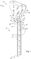
- the figure 1 shows a system 10 comprising a carrier rail 11 and a plate 12.
- Rail 11 is shown here placed upright, under plate 12, with its top facing plate 12.
- the carrier rail 11 is a profiled metal element, here with a U-shaped section.
- the rail 11 extends longitudinally from a first end 23 which can be seen at the bottom on the figure 1 , to a second end 24 located at its top and at which it has a free edge 25.
- the rail 11 comprises a bottom 14 and two side wings 15 each connected by a longitudinal side to a respective longitudinal side of the bottom 14.
- the bottom 14 has a series of openings 20 of predetermined contour arranged along the rail 11 according to a regular pitch.
- Each opening 20 has a keyhole shape longitudinally oriented like the general orientation of the rail 11.
- Each opening 20 has a wide portion 21 and a narrow portion 22 extending the wide portion 21.
- the openings 20 are here all identical and oriented in the same way.
- the rail 11 is oriented so that the narrow portion 22 is above the wide portion 21, that is to say with the narrow portion 22 which is turned towards the plate 12.
- the openings 20 are configured for the passage of a fixing member such as a screw, for example when the rail 11 must be fixed to a wall.
- Rail 11 here forms part of a system for providing horizontal support to a cable tray (not shown).
- This system comprises the rail 11 and a bracket (not shown) having a portion configured to form said horizontal support when it is fixed to the rail 11, itself fixed vertically to a structure such as a wall or a ceiling.
- the plate 12 is used to fix the rail 11 to a structure such as a ceiling.
- each side wall 16 has a series of openings (not shown to simplify the drawings) arranged along the rail 11 according to a regular pitch.
- Each opening of a side wing 15 is aligned with an opening of the other lateral wing 15 in a direction transverse to the general orientation of the rail 11, here a direction parallel to the bottom 14 and transverse to the side walls 16.
- Each of the openings is configured to receive a male member for fixing the console.
- the plate 12 will now be described in more detail in support of the figures 1 to 4 .
- the plate 12 is configured to be fixed to a support in a predetermined nominal orientation and to immobilize, while it is in the nominal orientation, an end section 30 of the rail 11 so that the rail 11 is placed upright with the end section 30 which is at its top.
- the plate 12 is shown in its predetermined nominal orientation, with the rail 11 which is arranged upright under the plate 12 but away from the latter.
- the support here is a ceiling 26 ( figure 4 , 11 and 14 ) to which the plate 12 is fixed by means of screws 27 shown schematically by dot-and-dash lines on the figure 4 , 11 and 14 .
- the plate 12 comprises a body 28 and a lock 29 movably mounted on the body 28.
- the plate 12 has a housing 31, delimited by the body 28 and the lock 29, provided with an opening 32 which is located at the bottom when the plate 12 is in its nominal orientation.
- the housing 31 is configured to receive, through the opening 32, the end section 30 of the rail 11.
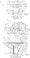
- the plate 12 is shown in an initial configuration that it has when it is in its nominal orientation and the end section 30 is outside the housing 31.
- lock 29 occupies an initial position and housing 31 is in an initial configuration.
- the body 28 is here made from a cut and bent metal plate.
- the assembly of the lock 29 on the body 28 is carried out during the bending of the metal plate of which the body is made.
- the shaped body 28 is therefore not, in practice, without the lock 29 mounted on it.
- the lock 29 is not shown on the figure 5 .
- the body 28 comprises a first portion 35 and a second portion 36 forming an extension of the first portion 35.
- the first portion 35 comprises a gutter 45 and a closing wall 46 of the gutter 45.
- the gutter 45 extends longitudinally between a first end 39 and a second end 40.
- the first end 39 forms the lower end of the gutter 45; while the second end 40 forms the upper end of the gutter 45; the gutter 45 thus being generally oriented in a substantially vertical direction.
- the gutter 45 comprises a bottom 34, a first lateral wing 37 and a second lateral wing 38 each connected by a first longitudinal side to a respective longitudinal side of the bottom 34.
- the first side wing 37 forms a first wall and the second side wing 38 forms a second wall.
- the bottom 34 has a projection 87 projecting from the side of the internal space 44 and extending all along the bottom 34.
- the projection 87 is configured to be received between the flanges 19 of the rail 11 when the latter is received in the housing 31 and immobilized by the plate 12.
- the first and second lateral wings 37 and 38 extend facing each other and each have a conformation which is the mirror image of the conformation of the other lateral wing.
- Each of the side wings 37 and 38 has a lower edge 47 located at the first end 39, an upper edge 48 located at the second end 40 and a side edge 49 located on the side opposite the bottom 34.
- Side edge 49 connects bottom edge 47 to top edge 48.
- the closure wall 46 connects the respective upper edges 48 of the side wings 37 and 38 by extending from the side edges 49, where it has a side edge 53, to the right of the bottom 34.
- the closure wall 46 delimits the internal space 44 of the gutter 45 on the side of its upper end 40.
- the bottom 34 extends longitudinally between a lower edge 41 located at the same level as the lower edges 47 of the side wings 37 and 38, and an upper edge 42, opposite the lower edge 41, extending opposite and at a certain distance of the closure wall 46, so that an opening 55 opening into the internal space 44 is formed between the upper edge 42 and the closure wall 46.
- the second portion 36 extends the first portion 35 such that the first portion 35 and the second portion 36 extend on either side of the bottom 34.
- the second portion 36 comprises a first extension wall 56 which extends a portion of the first lateral wing 37 located to the right of the opening 55.
- the second portion 36 further comprises a second extension wall 52 and a third extension wall 51 which respectively extend the second lateral wing 38 and the closure wall 46.
- the third extension wall 51 and the closure wall 46 together form a fixing wall 58 of the plate 12 of rectangular shape.
- the fixing wall 58 comprises two through holes 59 formed respectively in the closing wall 46 and the third extension wall 51 for the passage of the fixing screws 27.
- the fixing wall 58 is arranged lying down, for example against the ceiling 26, while the side wings 37 and 38 and the bottom 34 are arranged upright.
- the second extension wall 52 and the second side wing 38 form a side cheek 60.
- the side cheek 60 has a rectangular portion directly connected to a longitudinal side of the fixing wall 58 and a trapezoidal portion extending the rectangular portion by narrowing towards the lower end 39 of the gutter 45.
- the body 28 also has slots made in each of the side wings 37 and 38.
- Each light provided in one side wing is opposite a corresponding light provided in the other side wing, two facing lights thus forming a pair of lights.
- the body 28 has a pair of lower slots 61 and a pair of upper slots 62 arranged above the pair of lower slots 61.
- the slots 61 and 62 each have a generally elongated shape in a direction inclined towards the closure wall 46 and towards the side opposite the bottom 34, or in other words, inclined upwards and towards the outside of the housing 31 when the plate 12 is in the nominal orientation.
- Each slot extends longitudinally between a lower end edge 74 and an upper end edge 75 opposite the lower end edge 74 and extends laterally between a lower longitudinal edge 72 and an upper longitudinal edge 73 located opposite of the lower longitudinal edge 72.
- the lower end and longitudinal edges 74 and 72 are located respectively below the upper end and longitudinal edges 75 and 73.
- the slots 61 and 62 have respective identical contours.
- Each light has a narrow portion 63 and a wide portion 64 extending the narrow portion 63 towards the side opposite the bottom 34, or in other words towards the outside of the housing 31.
- the longitudinal edges 72 and 73 of the slots 61 and 62 form guide ramps configured to guide the movement of the lock 29 relative to the body 28 of the plate 12 in the direction inclined upwards and towards the outside of the housing 31 when the plate 12 is in the nominal orientation.
- Each of the side wings 37 and 38 further comprises a folding tab 65 rooted in an upper edge 75 of the respective lower slot 61.
- the folding tab 65 is configured to be deformable at its proximal end so that it can adopt a first stable position in which it is away from the lower lumen 61 and a second stable position in which it is folded back into the lumen. lower 61.
- the lock 29 is here made from a cut and bent rigid metal plate, the lock 29 thus being a rigid element.
- Latch 29 has a main wall 66, four mounting lugs 67 and two projecting tabs 68.
- the main wall 66 has a generally rectangular shape and extends longitudinally between a first end 69 and a second end 70 opposite the first end 69.
- the first end 69 faces downwards and therefore forms a lower end of the main wall 66; while the second end 70 faces upwards and therefore forms an upper end of the main wall 66; the main wall 66 thus being generally oriented upright.
- the main wall 66 has two opposite longitudinal edges 71 each joining the first end 69 and the second end 70.
- the main wall 66 has successively, from its lower end 69 towards its upper end 70, a first straight portion 76, a first inclined portion 77, a junction portion 78, a second straight portion 79 and a second inclined portion 80.
- the first inclined portion 77 extends the first straight portion 76 longitudinally while presenting the same inclination as the inclined direction in which the lock 29 is guided relative to the body.
- the main wall 66 also has at its lower end 69 a return 88 extending the first straight portion 76 on the same side as the inclined portion 77.
- a first projection lug 68 projects from the straight portion 76, on the side opposite to the side towards which the inclined portion 77 extends, that is to say towards the inside of the housing 31 when the lock is mounted on the body. 28.
- the protruding tab 68 is separated from the straight portion 76 by a cutout, the tab 68 extending between a proximal end by which it is connected to the straight portion 76 and a distal end at which it has a free edge.
- the tab 68 here has an I-shape and is longitudinally oriented in a direction inclined upwards and towards the inside of the housing 31 when the lock is mounted on the body 28.
- the second inclined portion 80, the second straight portion 79 and the second projecting tab 68 are arranged relative to each other like the first inclined portion 77, the first straight portion 76 and the first projecting tab 68; the first straight portion 76 and the second straight portion 79 being coplanar.
- a first mounting lug 67 projects from a respective longitudinal edge 71 of the main wall 66 while a second mounting lug 67, placed opposite the first mounting lug 67, projects from the other longitudinal edge 71 of the wall main 66.
- the first and second mounting lugs 67 are thus located on either side of the main wall 66 and each extending transversely beyond the main wall 66.
- the first and second mounting ears 67 are each formed by an extension of the first inclined portion 77 having the same inclination as the inclined portion 77, so that the mounting ears 67 each have a lower inclined guide surface 81 and a upper inclined guide surface 82, opposite lower inclined guide surface 81.
- Each mounting ear 67 has an L-shape with a first branch 83 which extends from a respective longitudinal edge 71 of the main wall 66 and a second branch 84 which extends the first branch 83 towards the side where the first portion is located. right 76, that is to say towards the inside of the housing 31 when the lock is mounted on the body 28.
- the first mounting lug 67 and the second mounting lug 67 located on either side of the main wall 66, at the level of the first inclined portion 77, form a pair of lower mounting lugs 67.
- Two other mounting lugs 67 located at the level of the second inclined portion 80 form a pair of upper mounting lugs 67.
- the latch 29 further comprises a boss 85, located under the first projecting lug 68 and projecting on the same side as this lug 68.
- the lock 29 is mounted on the body 28 of the plate 12 with its main wall 66 disposed between the side flanges 37 and 38, facing the bottom 34 of the gutter 45, between the side opening 54 and the bottom 34 of the gutter 45; while the mounting lugs 67 are each engaged in a respective lumen of the body 28.
- the ears 67 of the lower pair of ears are engaged in the slots 61 of the lower pair of slots; while the ears 67 of the upper pair of ears are engaged in the lights 62 of the upper pair of lights.
- the housing 31 is a portion of the internal space 44 of the gutter 45, delimited laterally by an internal face of the bottom 34, which is turned towards the lock 29, an internal face of the lock 29, which is turned towards the bottom 34, and internal faces opposite portions 86 of the side wings 37 and 38 which are between the bottom 34 and the lock 29.
- the opening 32 is a portion of the lower opening 43 of the gutter 45 which is delimited on the side opposite the bottom 34 by the internal face of the lock 29.
- the opening 32 therefore also changes size with the position of the lock 29 with respect to the body 28.
- the lugs 68 project from the internal face of the lock 29 in the housing 31 and each extend at least partially opposite the opening 32.
- each mounting lug 67 rests on the lower end edge 74 of the slot 61 or 62 in which it is engaged, the portion of the side wing delimiting the lower end edge 74 of the slot being received between the wall main 66 and the second leg 84 of the mounting lug 67.
- each of the mounting lugs 67 is free to slide in the slot 61 or 62 in which it is engaged, between the lower end edge 74 and the upper end edge 75; the lock 29 thus being movable in translation relative to the body 28 between two extreme positions.
- a first extreme position corresponds to the initial position of the lock 29 illustrated on the figures 1 to 4 ; a second extreme position in which the lock 29 is farther from the bottom 34 of the gutter 45 is illustrated on the figures 12 to 14 .
- the lower guide surface 81 is configured to slide flat on the lower longitudinal edge 72 opposite; while the upper guide surface 82 is configured to slide flat on the upper longitudinal edge 73 opposite.
- the lock 29 is in a locking position in which the housing 31 is in an immobilization configuration.
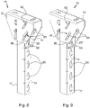
- the folding tabs 65 can be folded back into the lower slots 61, so that the latch 29 cannot move away from its locking position by moving out of the housing. 31; the tabs 65 thus forming secondary locking members of the system 10 ( Figure 9 ).
- the end section 30 is received in the housing 31 with the bottom 14 of the rail 11 facing the lock 29 and the returns 17 facing the bottom 34 of the gutter 45.
- the end section 30 received in the housing 31 of the plate 12 here comprises two openings 20, that is to say that two openings 20 are in the housing 31.
- each projecting lug 68 is engaged in a respective opening 20 of the bottom 14 of the rail 11 so that the lug 68 comes into contact by its free edge with an upper edge of the opening 20 in which it is engaged, which prevents the withdrawal of the end section 30 of the rail 11 from the housing 31.
- boss 85 comes into contact with the lower edge of the opening 20 of the rail 11 in which the first projecting lug 68 is engaged. As explained below, the boss 85 here forms a member for indexing the position of the lock 29 with respect to the openings 20 of the bottom 14 of the rail 11.
- the plate 12 also holds the rail 11 when the latter is oriented in the opposite direction to that illustrated, that is to say with the narrow portion 22 of the openings 20 facing downwards rather than upwards. .
- Each straight portion 76 and 79 of the main wall 66 comes into contact with an outer face 89 of the bottom 14 of the rail 11; while each flange 18 of the returns 17 of the rail comes into contact with the internal face of the bottom 34 of the gutter 45; that the projection 87 is received between the flanges 19 of the rail 11; and that each side wall 16 of rail 11 comes into contact with an internal face of a respective portion 86 of side flanges 37 and 38.
- the housing 31 of the plate 12 here has a generally parallelepipedic shape corresponding to the shape of the end section 30 of the rail 11.
- End section 30 is thus held in housing 31 in directions other than the longitudinal direction of rail 11.
- Rail 11 oriented as on the figure 1 , is introduced by a user into the housing 31 through the opening 32.
- the end section 30 thus drives the latch 29 upwards and outwards at least to a cusp position provided so that each of the lugs 68 is more towards the outside of the housing 31 than the outer face 89 of the bottom 14 of end section 30.
- the reversal position can be for example that illustrated on the figures 12 to 14 , where the rail is not shown to simplify the drawing.
- the latch 29 can then, under the effect of its own weight, slide down and towards the end section 30, which automatically inserts each tab 68 into the respective opening 20 of the bottom 14.
- the rail 11 is released by the user and can, under the effect of its own weight, tend to come out of the housing 31 and thus cause the lock 29 to slide even more. downwards and towards the bottom 34 of the gutter 45 to cause the housing 31 to pass automatically to its immobilization configuration.
- the first projecting tab 68 will be temporarily introduced into the opening 20 of the bottom 14 of the rail 11 closest to its free edge 25, before coming out. and to be finally inserted into the next opening 20.
- FIGS. 15 to 18 illustrate an alternative embodiment of the lock identical to that described above except that the projecting lugs 68 are replaced by projecting lugs 168 made differently.
- the protruding tab 168 here has a wedge shape, a first edge 90 of which extends from the straight portion 76 to a second edge 91 which extends the first edge 90 to the straight portion 76.
- the second edge 91 has a lying orientation when the lock is mounted on the body 28.
- the first edge 90 comprises an inclined section and a straight section.
- the inclined section extends between the straight portion 76 and the straight section, which extends between the inclined section and the edge 91.
- the straight section is upright and the inclined section extends in an upward and downward inclined direction. inside the housing 31 when the lock is mounted on the body 28.
- the tab 168 connects to the straight portion 76 by a third edge 92 which connects the first edge 90 and the second edge 91, the third edge 92 being longitudinally oriented like the main wall 66.
- the second protruding tab 168 is arranged in a similar manner vis-à-vis the second straight portion 79.
- each projecting lug 168 is engaged in a respective opening 20 of the bottom 14 of the rail 11 so that the lug 168 comes into contact by its second edge 91 with an upper edge of the opening 20 in which it is engaged.
- each of the tabs 68 and 168 has a ramp formed, for the tab 68, by its face facing the bottom 34 and, for the tab 168, by the inclined section of the edge 90; and that each of the tabs 68 and 168 has a stop formed, for the tab 68, by its end edge and, for the tab 168, by the edge 91.
- the body 28 and the lock 29 are each obtained from a cut and bent metal plate.
- the portions of the plate intended to form the side flanges 37 and 38 are folded towards each other while the lock 29 is interposed between them so that its mounting ears 67 each engage in a wide portion 64 of a slot 61 or 62 respectively.
- the bottom 34 of the gutter 45 is part of a portion of the plate which is directly connected by a first end to the portion of the plate forming the first side flange 37; while at its opposite end, this portion has two extensions 93 and 94 which each extend the bottom 34 through a respective slot formed in the side cheek 60, at the junction between the second side wing 38 and the second wall of extension 52. Each extension 93 and 94 partially protrudes beyond the side cheek 60.
- the extension 94 located below the extension 93, has a folded portion 95 extending opposite the outer surface of the second extension wall 52.
- This folded portion 95 forms an abutment which opposes this that the side flanges 37 and 38 deviate from each other, in particular when the rail 11 is subjected to forces transverse to its general orientation.
- the body 28 and the lock 29 are here both made of the same metallic material whose elastic deformation limit is between 280 and 355 N/mm 2 .
- the Young's modulus of the material here is approximately 210,000 MPa.
- the thickness of the plate from which the lock 29 is obtained is greater than the thickness of the plate from which the body 28 is obtained, so that the lock 29 has greater rigidity.
- the plate from which the body 28 is obtained here has a thickness of approximately 3 mm, so that it is relatively easy to deform it, which is convenient for making the folds making it possible to obtain the body 28, and also to fold down the tabs 65.
- the plate from which the lock 29 is obtained here has a thickness of approximately 4 mm, so that it is rigid, that is to say particularly difficult to deform. This prevents the lug 68 or 168 from deforming when it is subjected to the forces exerted by the rail 11, which must support a load which may be relatively high.
- the force exerted on the lock 29 by the rail 11 is directed downwards so that it is normally not useful to maintain the lock in the locking position.
- the folding tabs 65 allow such a precautionary support, in the event that an unexpected force is exerted upwards, for example following an accidental impact.
- the lock comprises, at its upper end, a ramp inclined upwards and towards the outside of the housing configured to drive the rail and the lock towards each other when the free edge of the rail enters in contact with the ramp during the continuation of the driving movement of the end section after the reversal position has been reached.
Landscapes
- Engineering & Computer Science (AREA)
- Architecture (AREA)
- Civil Engineering (AREA)
- Structural Engineering (AREA)
- Connection Of Plates (AREA)
- Pinball Game Machines (AREA)
- Endoscopes (AREA)
- Sampling And Sample Adjustment (AREA)
Claims (14)
- System mit einer Tragschiene (11) und einer Platine (12), die dazu ausgelegt ist, in einer vorbestimmten nominalen Ausrichtung an einem Träger (26) befestigt zu werden und, wenn sie sich in der nominalen Ausrichtung befindet, einen Endabschnitt (30) der Schiene (11) so festzulegen, dass die Schiene (11) mit dem an ihrem Scheitelpunkt befindlichen Endabschnitt (30) aufrecht angeordnet ist, wobei die Schiene (11) ein Profilelement mit vorbestimmtem Querschnitt ist, das einen Boden (14) aufweist, der in dem Endabschnitt (30) zumindest eine Öffnung (20) mit vorbestimmter Kontur aufweist, die sich an einer vorbestimmten Stelle befindet, wobei die Platine (12) eine Aufnahme (31) zum Aufnehmen des Endabschnitts (30) der Schiene (11) enthält, wobei die Aufnahme (31) eine Öffnung (32) zum Einführen des Endabschnitts (30) aufweist, die dann, wenn die Platine (12) in der nominalen Ausrichtung ist, unten liegt, wobei die Aufnahme (31) eine Festlegestellung des Endabschnitts (30) der Schiene (11) zulässt, in der eine vorspringende Lasche (68; 168) in die Öffnung (20) des Bodens (14) eingefügt ist und das Entweichen des Endabschnitts (30) der Schiene (11) verhindert, während die Aufnahme (31) seitlich durch Flächen begrenzt ist, die den Endabschnitt (30) in anderen Richtungen als der Längsrichtung der Schiene (11) festhalten, wobei die Platine (12) dazu ausgelegt ist, dass die Aufnahme (31) automatisch die Festlegestellung einnimmt, wenn der Endabschnitt (30) der Schiene (11) in diese eingeschoben ist und dann dazu neigt, daraus zu entweichen;
dadurch gekennzeichnet, dass die Platine (12) einen Körper (28) und einen bezüglich des Körpers (28) beweglichen Riegel (29) enthält, wobei der Riegel (29) starr ist und eine die Aufnahme (31) begrenzende Fläche aufweist, die dazu vorgesehen ist, dem Boden (14) des Endabschnitts (30) gegenüberzuliegen, wobei der starre Riegel (29) auch die vorspringende Lasche (68; 168) aufweist, die somit starr ist und von der Fläche, die der Riegel (29) aufweist, vorspringt, wobei der Riegel (29) zwischen einer Verriegelungsposition, in der sich die Aufnahme (31) in der Festlegestellung befindet, und einer Umkehrposition beweglich ist, die dazu vorgesehen ist, dass die Lasche (68; 168) weiter aus der Aufnahme (31) herausragt als die Außenfläche (89) des Bodens (14) des Endabschnitts (30), wobei der Riegel (29) in Bezug auf den Körper (28) der Platine (12) in einer geneigten Richtung nach oben und aus der Aufnahme (31) heraus geführt wird, wenn sich die Platine (12) in der nominalen Ausrichtung befindet, so dass beim Einschieben des Endabschnitts (30) der Schiene (11) in die Aufnahme (31) dann, wenn sich die Platine (12) in der nominalen Ausrichtung befindet, der Endabschnitt (30) den Riegel (29) nach oben und aus der Aufnahme (31) heraus zumindest bis zur Umkehrposition mitnimmt, dass dann durch eine Bewegung des Riegels (29) und der Schiene (11) aufeinander zu die Lasche (68; 168) in die genannte Öffnung (20) des Bodens (14) eingeführt wird und dass anschließend durch eine Bewegung des Endabschnitts (30) der Schiene (11) nach unten der Riegel (29) mitgenommen wird, um die Aufnahme (31) in die Festlegestellung zu überführen. - System nach Anspruch 1, dadurch gekennzeichnet, dass die Bewegung des Riegels (29) und der Schiene (11) aufeinander zu, durch welche die Lasche (68; 168) in die Öffnung (20) des Bodens (14) eingeführt wird, auf die Gewichtskraft des Riegels (29) zurückzuführen ist, die dann, wenn sich die Platine (12) in der nominalen Ausrichtung befindet, den Riegel (29) nach unten und damit in Richtung der Schiene (11) bewegt, nachdem die Umkehrposition erreicht wurde.
- System nach einem der Ansprüche 1 und 2, dadurch gekennzeichnet, dass der Riegel (29) eine Hauptwand (66) aufweist, die aufrecht angeordnet ist, wenn sich die Platine (12) in ihrer nominalen Ausrichtung befindet, sowie zumindest zwei Montageansätze (67), die sich auf beiden Seiten der Hauptwand (66) befinden und sich jeweils quer über die Hauptwand (66) hinaus erstrecken, wobei die Hauptwand (66) zumindest einen geraden Abschnitt (76, 79) umfasst, der die die Aufnahme (31) begrenzende Fläche aufweist, wobei die vorspringende Lasche (68; 168) von dem geraden Abschnitt (76, 79) in Richtung der Aufnahme (31) vorspringt, wobei der gerade Abschnitt (76, 79) dazu ausgelegt ist, mit dem Boden (14) der Schiene (11) in Kontakt zu gelangen, wenn sich die Aufnahme (31) in der Festlegestellung befindet, wobei die Montageansätze (67) dazu ausgelegt sind, auf Führungsrampen (72, 73) zu gleiten, die der Körper (28) aufweist, um die Bewegung des Riegels (29) in Bezug auf den Körper (28) in der geneigten Richtung nach oben und aus der Aufnahme (31) heraus zu führen, wenn sich die Platine (12) in der nominalen Ausrichtung befindet.
- System nach Anspruch 3, dadurch gekennzeichnet, dass die vorspringende Lasche (68; 168) durch einen Ausschnitt von dem geraden Abschnitt (76, 79) getrennt ist, wobei sich die Lasche (68; 168) zwischen einem proximalen Ende, mit dem sie sich an den geraden Abschnitt (76, 79) anschließt, und einem distalen Ende, an dem sie eine freie Kante aufweist, erstreckt; wobei die Lasche (68; 168) dazu ausgelegt ist, mit ihrer freien Kante eine obere Kante der Öffnung (20) des Bodens (14) zu berühren, wenn sich die Aufnahme (31) in Festlegestellung befindet.
- System nach einem der Ansprüche 3 oder 4, dadurch gekennzeichnet, dass die Hauptwand (66) einen geneigten Abschnitt (77, 80) aufweist, der den geraden Abschnitt (76, 79) in Längsrichtung fortsetzt und die gleiche Neigung aufweist wie die geneigte Richtung, in der der Riegel (29) in Bezug auf den Körper (28) geführt wird, wobei die Montageansätze (67) jeweils aus einem Fortsatz des geneigten Abschnitts (77, 80) mit der gleichen Neigung gebildet sind, so dass die Montageansätze (67) jeweils eine geneigte Führungsfläche (81, 82) aufweisen, die dazu ausgelegt ist, flach auf einer jeweils gegenüberliegenden Führungsrampe (72, 73) zu gleiten.
- System nach einem der Ansprüche 3 bis 5, dadurch gekennzeichnet, dass der Riegel (29) zwei zusätzliche Montageansätze (67) aufweist, die auf beiden Seiten der Hauptwand (66) angeordnet und dazu ausgelegt sind, auf zusätzlichen Führungsrampen (72, 73) zu gleiten, die der Körper (28) aufweist, um die Bewegung des Riegels (29) in Bezug auf den Körper (28) zu führen.
- System nach einem der Ansprüche 3 bis 6, dadurch gekennzeichnet, dass der Boden (14) des Endabschnitts (30) der Schiene (11) eine zusätzliche Öffnung (20) mit vorbestimmter Kontur aufweist, die sich an einer vorbestimmten Stelle befindet, die sich von der Stelle der Öffnung (20) im Boden (14) unterscheidet; und die Hauptwand (66) des Riegels (29) einen zusätzlichen geraden Abschnitt (76, 79) und eine zusätzliche vorspringende Lasche (68; 168) aufweist, die wie der gerade Abschnitt (76, 79) und die vorspringende Lasche (68; 168) relativ zueinander angeordnet sind, wobei der gerade Abschnitt (76, 79) und der zusätzliche gerade Abschnitt (76, 79) koplanar verlaufen, wobei die zusätzliche vorspringende Lasche (68; 168) in die zusätzliche Öffnung (20) des Bodens (14) eingeführt ist, wenn sich die Aufnahme (31) in der Festlegestellung befindet.
- System nach einem der Ansprüche 3 bis 7, dadurch gekennzeichnet, dass die Führungsrampen (72, 73), die der Körper (28) der Platine (12) aufweist, aus Schlitzen (61, 62) in gegenüberliegenden Wänden (37, 38) gebildet sind, die der Körper (28) der Platine (12) aufweist, wobei die Hauptwand (66) des Riegels (29) zwischen den gegenüberliegenden Wänden (37, 38) angeordnet ist und die Montageansätze (67) des Riegels (29) jeweils in einen entsprechenden Schlitz (61, 62) eingreifen.
- System nach Anspruch 8, dadurch gekennzeichnet, dass zumindest eine der dem Körper (28) gegenüberliegenden Wände (37, 38) eine umklappbare Zunge (65) aufweist, die in einer oberen Kante (75) eines der Schlitze (61) verankert und dazu ausgelegt ist, an ihrem proximalen Ende verformt werden zu können, so dass sie eine erste stabile Position einnehmen kann, in der sie von dem Schlitz (61) beabstandet ist, sowie eine zweite stabile Position, in der sie in den Schlitz (61) eingeklappt ist, um zu verhindern, dass der in diesem Schlitz (61) aufgenommene Montageansatz (67) des Riegels (29) aus der Aufnahme (31) herausgleitet, wenn sich der Riegel (29) in seiner Verriegelungsposition befindet.
- System nach Anspruch 8, dadurch gekennzeichnet, dass jeder Montageansatz (67) des Riegels (29) eine L-Form mit einem ersten Schenkel (83), der sich von einer jeweiligen Längskante (71) der Hauptwand (66) quer zur Hauptwand (66) erstreckt, und einem zweiten Schenkel (84), der den ersten Schenkel (83) in die Aufnahme (31) hinein fortsetzt, aufweist; wobei der durch den ersten Schenkel (83), den zweiten Schenkel (84) und die Hauptwand (66) begrenzte Raum dazu ausgelegt ist, einen Abschnitt der Wand (37, 38) des Körpers (28) aufzunehmen, der die untere Kante (74) des in dieser Wand (37, 38) ausgebildeten Schlitzes (61, 62) begrenzt, in den der Montageansatz (67) eingreift.
- System nach einem der Ansprüche 8 bis 10, dadurch gekennzeichnet, dass jeder Schlitz (61, 62) einen schmäleren Abschnitt (63) und einen breiteren Abschnitt (64) aufweist, der den schmäleren Abschnitt (63) aus der Aufnahme (31) heraus fortsetzt.
- System nach einem der Ansprüche 1 bis 11, dadurch gekennzeichnet, dass der Riegel (29) eine vorspringende Erhebung (85) aufweist, die sich unter der vorspringenden Lasche (68; 168) des Riegels (29) befindet und dazu ausgelegt ist, mit einer unteren Kante der Öffnung (20) der Schiene (11) in Kontakt zu gelangen, in die die vorspringende Lasche (68; 168) eingreift, wenn sich die Aufnahme (31) in der Festlegestellung befindet.
- System nach einem der Ansprüche 1 bis 12, dadurch gekennzeichnet, dass der Körper (28) der Platine (12) eine Rinne (45) mit einem Boden (34) und zwei Seitenflügeln (37, 38) aufweist, die sich jeweils an eine jeweilige Längsseite des Bodens (34) anschließen und sich einander gegenüberliegend erstrecken, wobei eine Hauptwand (66) des Riegels (29) zwischen den Seitenflügeln (37, 38) angeordnet ist, wobei die Hauptwand (66) des Riegels (29) und der Boden (34) der Rinne (45) einander gegenüberliegen; wobei die Flächen, die die Aufnahme (31) in der Festlegestellung begrenzen, aus den Innenflächen des Bodens (34) der Rinne (45), der Seitenflügel (37, 38) der Rinne (45) und des Riegels (29) gebildet sind.
- System nach einem der Ansprüche 1 bis 13, dadurch gekennzeichnet, dass der Riegel (29) aus einer starren Stanzbiegeplatte aus Metall hergestellt ist.
Applications Claiming Priority (2)
| Application Number | Priority Date | Filing Date | Title |
|---|---|---|---|
| FR1662697A FR3060884B1 (fr) | 2016-12-16 | 2016-12-16 | Systeme comportant un rail porteur et une platine configuree pour etre fixee a un support et immobiliser le rail dispose debout sous le support |
| PCT/FR2017/053618 WO2018109420A1 (fr) | 2016-12-16 | 2017-12-15 | Système comportant un rail porteur et une platine configurée pour être fixée à un support et immobiliser le rail disposé debout sous le support |
Publications (2)
| Publication Number | Publication Date |
|---|---|
| EP3555975A1 EP3555975A1 (de) | 2019-10-23 |
| EP3555975B1 true EP3555975B1 (de) | 2022-04-20 |
Family
ID=59031002
Family Applications (1)
| Application Number | Title | Priority Date | Filing Date |
|---|---|---|---|
| EP17828947.6A Active EP3555975B1 (de) | 2016-12-16 | 2017-12-15 | System mit einer trägerschiene und einer platte, die zur befestigung an einem träger und zur immobilisierung der unter dem träger stehenden schiene konfiguriert ist |
Country Status (4)
| Country | Link |
|---|---|
| EP (1) | EP3555975B1 (de) |
| ES (1) | ES2916333T3 (de) |
| FR (1) | FR3060884B1 (de) |
| WO (1) | WO2018109420A1 (de) |
Families Citing this family (4)
| Publication number | Priority date | Publication date | Assignee | Title |
|---|---|---|---|---|
| NL2025855B1 (en) * | 2020-06-18 | 2022-02-17 | Walraven Holding Bv J Van | Wall mounting bracket for a mounting rail and method of manufacture thereof |
| DE202021104122U1 (de) | 2021-08-03 | 2022-11-07 | OBO Bettermann Hungary Kft. | Kopfanschlussteil zum Befestigen eines Hängestiels eines Kabeltragsystems an einer Decke |
| DE202024104825U1 (de) | 2024-08-27 | 2026-01-14 | Obo Bettermann Hungary Kft | Befestigungsanordnung zwischen einem Halter und einer Kabeltragkomponente sowie Halter mit einem daran angeschlossenen Anschlussadapter |
| DE102024124552B3 (de) * | 2024-08-28 | 2025-09-04 | Obo Bettermann Hungary Kft | Befestigungsanordnung zwischen einem Halter und einer Kabeltragkomponente sowie Halter mit einem daran angeschlossenen Anschlussadapter |
Family Cites Families (3)
| Publication number | Priority date | Publication date | Assignee | Title |
|---|---|---|---|---|
| FR2853026B1 (fr) | 2003-03-31 | 2007-01-05 | Icm Group | Dispositif de fixation sur une surface, notamment un plafond, destine a supporter un profil perfore |
| EP1589626A1 (de) * | 2004-04-19 | 2005-10-26 | Vergokan | Rastmontierte Aufhängungsanordnung für Kabelkanäle |
| FR3006511B1 (fr) | 2013-05-31 | 2015-06-26 | Legrand France | Systeme pour fournir un support horizontal a un objet tel qu'un chemin de cables et rail pour un tel systeme |
-
2016
- 2016-12-16 FR FR1662697A patent/FR3060884B1/fr active Active
-
2017
- 2017-12-15 EP EP17828947.6A patent/EP3555975B1/de active Active
- 2017-12-15 WO PCT/FR2017/053618 patent/WO2018109420A1/fr not_active Ceased
- 2017-12-15 ES ES17828947T patent/ES2916333T3/es active Active
Also Published As
| Publication number | Publication date |
|---|---|
| ES2916333T3 (es) | 2022-06-30 |
| FR3060884B1 (fr) | 2019-05-24 |
| EP3555975A1 (de) | 2019-10-23 |
| FR3060884A1 (fr) | 2018-06-22 |
| WO2018109420A1 (fr) | 2018-06-21 |
Similar Documents
| Publication | Publication Date | Title |
|---|---|---|
| EP3555975B1 (de) | System mit einer trägerschiene und einer platte, die zur befestigung an einem träger und zur immobilisierung der unter dem träger stehenden schiene konfiguriert ist | |
| EP2808964B1 (de) | System, das als waagrechte Halterung für einen Gegenstand wie einen Kabelkanal dienen soll, und Schiene für ein solches System | |
| CA2262494C (fr) | Eclisse d'assemblage pour troncons de chemins de cables et troncons de chemins de cables obtenus | |
| FR2889268A1 (fr) | Ensemble de fixation temporaire de deux elements, procede de montage d'une garniture interieure de portiere de vehicule et panneau de portiere realise selon ce procede de montage | |
| EP1912299B1 (de) | Elektrisches Gerät, das zur Befestigung auf einer Stützschiene vorgesehen ist, und entsprechendes Montageverfahren | |
| FR2820553A1 (fr) | Accessoire pour goulotte et ensemble comprenant un tel accessoire et une goulotte dont le socle est specialement adapte audit accessoire | |
| EP1357650A1 (de) | Verbindungsvorrichtung für elektronisches Gehäuse | |
| EP2369219B1 (de) | Befestigungsvorrichtung für Flachbildschirm | |
| FR2978509A1 (fr) | Accessoire de blocage d'un support d'appareillage dans une paroi creuse | |
| FR3013159A1 (fr) | Support pour appareillage electrique de faible epaisseur | |
| EP1354745A1 (de) | Befestigungsvorrichtung eines funktionellen Organes auf einem Autoteil der Fahrzeugstruktur und Strukturteil, die zum Teil eine solche Vorrichtung integrieren | |
| EP2369698B1 (de) | Schienenauflagerung zur Montage von elektrischen Geräten in einem elektrischen Schaltkasten | |
| EP3503322B1 (de) | Halterung für elektrische geräte, die ein montagelement aufnimmt | |
| FR2804464A1 (fr) | Dispositif de solidarisation et mecanisme de manoeuvre d'une installation de fermeture ou de protection solaire comprenant un tel dispositif | |
| EP3503323B1 (de) | Halterung für elektrische geräte, die mit einem schiebeplättchen ausgestattet ist | |
| EP1471616A1 (de) | Haltevorrichtung an einer Fläche, insbesondere einer Decke, zur Befestigung eines Lochprofils | |
| FR2957725A1 (fr) | Coffret ou tableau de distribution electrique comportant un rail de montage d'appareillages electriques amovible | |
| WO2013156693A1 (fr) | Système de verrouillage à cliquet | |
| WO2011012778A2 (fr) | Boîte électrique de sol à moyens de montage rapide d'un module de connexion électrique | |
| EP1722111B1 (de) | Befestigungselement zur Befestigung eines Metallprofils auf einem Träger | |
| EP1717106B1 (de) | Anordnung eines Elektonikgehäuseträgers in einem Kraftfahrzeug | |
| EP1191657B1 (de) | Vorrichtung zur Befestigung eines Kabelkanals auf einem von einer Wand versetzten Sockel | |
| FR2620759A1 (fr) | Charniere demontable | |
| FR2569899A1 (fr) | Boitier modulaire pour appareillage electrique et modules correspondants | |
| EP4023830B1 (de) | Verriegelungssystem mit clip für bodenplatte |
Legal Events
| Date | Code | Title | Description |
|---|---|---|---|
| STAA | Information on the status of an ep patent application or granted ep patent |
Free format text: STATUS: UNKNOWN |
|
| STAA | Information on the status of an ep patent application or granted ep patent |
Free format text: STATUS: THE INTERNATIONAL PUBLICATION HAS BEEN MADE |
|
| PUAI | Public reference made under article 153(3) epc to a published international application that has entered the european phase |
Free format text: ORIGINAL CODE: 0009012 |
|
| STAA | Information on the status of an ep patent application or granted ep patent |
Free format text: STATUS: REQUEST FOR EXAMINATION WAS MADE |
|
| 17P | Request for examination filed |
Effective date: 20190617 |
|
| AK | Designated contracting states |
Kind code of ref document: A1 Designated state(s): AL AT BE BG CH CY CZ DE DK EE ES FI FR GB GR HR HU IE IS IT LI LT LU LV MC MK MT NL NO PL PT RO RS SE SI SK SM TR |
|
| AX | Request for extension of the european patent |
Extension state: BA ME |
|
| DAV | Request for validation of the european patent (deleted) | ||
| DAX | Request for extension of the european patent (deleted) | ||
| STAA | Information on the status of an ep patent application or granted ep patent |
Free format text: STATUS: EXAMINATION IS IN PROGRESS |
|
| 17Q | First examination report despatched |
Effective date: 20200714 |
|
| GRAP | Despatch of communication of intention to grant a patent |
Free format text: ORIGINAL CODE: EPIDOSNIGR1 |
|
| STAA | Information on the status of an ep patent application or granted ep patent |
Free format text: STATUS: GRANT OF PATENT IS INTENDED |
|
| INTG | Intention to grant announced |
Effective date: 20211115 |
|
| GRAS | Grant fee paid |
Free format text: ORIGINAL CODE: EPIDOSNIGR3 |
|
| GRAA | (expected) grant |
Free format text: ORIGINAL CODE: 0009210 |
|
| STAA | Information on the status of an ep patent application or granted ep patent |
Free format text: STATUS: THE PATENT HAS BEEN GRANTED |
|
| AK | Designated contracting states |
Kind code of ref document: B1 Designated state(s): AL AT BE BG CH CY CZ DE DK EE ES FI FR GB GR HR HU IE IS IT LI LT LU LV MC MK MT NL NO PL PT RO RS SE SI SK SM TR |
|
| REG | Reference to a national code |
Ref country code: GB Ref legal event code: FG4D Free format text: NOT ENGLISH |
|
| REG | Reference to a national code |
Ref country code: CH Ref legal event code: EP |
|
| REG | Reference to a national code |
Ref country code: DE Ref legal event code: R096 Ref document number: 602017056331 Country of ref document: DE |
|
| REG | Reference to a national code |
Ref country code: IE Ref legal event code: FG4D Free format text: LANGUAGE OF EP DOCUMENT: FRENCH |
|
| REG | Reference to a national code |
Ref country code: AT Ref legal event code: REF Ref document number: 1485950 Country of ref document: AT Kind code of ref document: T Effective date: 20220515 |
|
| REG | Reference to a national code |
Ref country code: ES Ref legal event code: FG2A Ref document number: 2916333 Country of ref document: ES Kind code of ref document: T3 Effective date: 20220630 |
|
| REG | Reference to a national code |
Ref country code: LT Ref legal event code: MG9D |
|
| REG | Reference to a national code |
Ref country code: NL Ref legal event code: MP Effective date: 20220420 |
|
| REG | Reference to a national code |
Ref country code: AT Ref legal event code: MK05 Ref document number: 1485950 Country of ref document: AT Kind code of ref document: T Effective date: 20220420 |
|
| PG25 | Lapsed in a contracting state [announced via postgrant information from national office to epo] |
Ref country code: NL Free format text: LAPSE BECAUSE OF FAILURE TO SUBMIT A TRANSLATION OF THE DESCRIPTION OR TO PAY THE FEE WITHIN THE PRESCRIBED TIME-LIMIT Effective date: 20220420 |
|
| PG25 | Lapsed in a contracting state [announced via postgrant information from national office to epo] |
Ref country code: SE Free format text: LAPSE BECAUSE OF FAILURE TO SUBMIT A TRANSLATION OF THE DESCRIPTION OR TO PAY THE FEE WITHIN THE PRESCRIBED TIME-LIMIT Effective date: 20220420 Ref country code: PT Free format text: LAPSE BECAUSE OF FAILURE TO SUBMIT A TRANSLATION OF THE DESCRIPTION OR TO PAY THE FEE WITHIN THE PRESCRIBED TIME-LIMIT Effective date: 20220822 Ref country code: NO Free format text: LAPSE BECAUSE OF FAILURE TO SUBMIT A TRANSLATION OF THE DESCRIPTION OR TO PAY THE FEE WITHIN THE PRESCRIBED TIME-LIMIT Effective date: 20220720 Ref country code: LT Free format text: LAPSE BECAUSE OF FAILURE TO SUBMIT A TRANSLATION OF THE DESCRIPTION OR TO PAY THE FEE WITHIN THE PRESCRIBED TIME-LIMIT Effective date: 20220420 Ref country code: HR Free format text: LAPSE BECAUSE OF FAILURE TO SUBMIT A TRANSLATION OF THE DESCRIPTION OR TO PAY THE FEE WITHIN THE PRESCRIBED TIME-LIMIT Effective date: 20220420 Ref country code: GR Free format text: LAPSE BECAUSE OF FAILURE TO SUBMIT A TRANSLATION OF THE DESCRIPTION OR TO PAY THE FEE WITHIN THE PRESCRIBED TIME-LIMIT Effective date: 20220721 Ref country code: FI Free format text: LAPSE BECAUSE OF FAILURE TO SUBMIT A TRANSLATION OF THE DESCRIPTION OR TO PAY THE FEE WITHIN THE PRESCRIBED TIME-LIMIT Effective date: 20220420 Ref country code: BG Free format text: LAPSE BECAUSE OF FAILURE TO SUBMIT A TRANSLATION OF THE DESCRIPTION OR TO PAY THE FEE WITHIN THE PRESCRIBED TIME-LIMIT Effective date: 20220720 Ref country code: AT Free format text: LAPSE BECAUSE OF FAILURE TO SUBMIT A TRANSLATION OF THE DESCRIPTION OR TO PAY THE FEE WITHIN THE PRESCRIBED TIME-LIMIT Effective date: 20220420 |
|
| PG25 | Lapsed in a contracting state [announced via postgrant information from national office to epo] |
Ref country code: RS Free format text: LAPSE BECAUSE OF FAILURE TO SUBMIT A TRANSLATION OF THE DESCRIPTION OR TO PAY THE FEE WITHIN THE PRESCRIBED TIME-LIMIT Effective date: 20220420 Ref country code: PL Free format text: LAPSE BECAUSE OF FAILURE TO SUBMIT A TRANSLATION OF THE DESCRIPTION OR TO PAY THE FEE WITHIN THE PRESCRIBED TIME-LIMIT Effective date: 20220420 Ref country code: LV Free format text: LAPSE BECAUSE OF FAILURE TO SUBMIT A TRANSLATION OF THE DESCRIPTION OR TO PAY THE FEE WITHIN THE PRESCRIBED TIME-LIMIT Effective date: 20220420 Ref country code: IS Free format text: LAPSE BECAUSE OF FAILURE TO SUBMIT A TRANSLATION OF THE DESCRIPTION OR TO PAY THE FEE WITHIN THE PRESCRIBED TIME-LIMIT Effective date: 20220820 |
|
| REG | Reference to a national code |
Ref country code: DE Ref legal event code: R097 Ref document number: 602017056331 Country of ref document: DE |
|
| PG25 | Lapsed in a contracting state [announced via postgrant information from national office to epo] |
Ref country code: SM Free format text: LAPSE BECAUSE OF FAILURE TO SUBMIT A TRANSLATION OF THE DESCRIPTION OR TO PAY THE FEE WITHIN THE PRESCRIBED TIME-LIMIT Effective date: 20220420 Ref country code: SK Free format text: LAPSE BECAUSE OF FAILURE TO SUBMIT A TRANSLATION OF THE DESCRIPTION OR TO PAY THE FEE WITHIN THE PRESCRIBED TIME-LIMIT Effective date: 20220420 Ref country code: RO Free format text: LAPSE BECAUSE OF FAILURE TO SUBMIT A TRANSLATION OF THE DESCRIPTION OR TO PAY THE FEE WITHIN THE PRESCRIBED TIME-LIMIT Effective date: 20220420 Ref country code: EE Free format text: LAPSE BECAUSE OF FAILURE TO SUBMIT A TRANSLATION OF THE DESCRIPTION OR TO PAY THE FEE WITHIN THE PRESCRIBED TIME-LIMIT Effective date: 20220420 Ref country code: DK Free format text: LAPSE BECAUSE OF FAILURE TO SUBMIT A TRANSLATION OF THE DESCRIPTION OR TO PAY THE FEE WITHIN THE PRESCRIBED TIME-LIMIT Effective date: 20220420 Ref country code: CZ Free format text: LAPSE BECAUSE OF FAILURE TO SUBMIT A TRANSLATION OF THE DESCRIPTION OR TO PAY THE FEE WITHIN THE PRESCRIBED TIME-LIMIT Effective date: 20220420 |
|
| PLBE | No opposition filed within time limit |
Free format text: ORIGINAL CODE: 0009261 |
|
| STAA | Information on the status of an ep patent application or granted ep patent |
Free format text: STATUS: NO OPPOSITION FILED WITHIN TIME LIMIT |
|
| 26N | No opposition filed |
Effective date: 20230123 |
|
| PG25 | Lapsed in a contracting state [announced via postgrant information from national office to epo] |
Ref country code: AL Free format text: LAPSE BECAUSE OF FAILURE TO SUBMIT A TRANSLATION OF THE DESCRIPTION OR TO PAY THE FEE WITHIN THE PRESCRIBED TIME-LIMIT Effective date: 20220420 |
|
| PG25 | Lapsed in a contracting state [announced via postgrant information from national office to epo] |
Ref country code: SI Free format text: LAPSE BECAUSE OF FAILURE TO SUBMIT A TRANSLATION OF THE DESCRIPTION OR TO PAY THE FEE WITHIN THE PRESCRIBED TIME-LIMIT Effective date: 20220420 |
|
| REG | Reference to a national code |
Ref country code: CH Ref legal event code: PL |
|
| REG | Reference to a national code |
Ref country code: BE Ref legal event code: MM Effective date: 20221231 |
|
| PG25 | Lapsed in a contracting state [announced via postgrant information from national office to epo] |
Ref country code: LU Free format text: LAPSE BECAUSE OF NON-PAYMENT OF DUE FEES Effective date: 20221215 |
|
| PG25 | Lapsed in a contracting state [announced via postgrant information from national office to epo] |
Ref country code: LI Free format text: LAPSE BECAUSE OF NON-PAYMENT OF DUE FEES Effective date: 20221231 Ref country code: IE Free format text: LAPSE BECAUSE OF NON-PAYMENT OF DUE FEES Effective date: 20221215 Ref country code: CH Free format text: LAPSE BECAUSE OF NON-PAYMENT OF DUE FEES Effective date: 20221231 |
|
| PG25 | Lapsed in a contracting state [announced via postgrant information from national office to epo] |
Ref country code: BE Free format text: LAPSE BECAUSE OF NON-PAYMENT OF DUE FEES Effective date: 20221231 |
|
| PG25 | Lapsed in a contracting state [announced via postgrant information from national office to epo] |
Ref country code: HU Free format text: LAPSE BECAUSE OF FAILURE TO SUBMIT A TRANSLATION OF THE DESCRIPTION OR TO PAY THE FEE WITHIN THE PRESCRIBED TIME-LIMIT; INVALID AB INITIO Effective date: 20171215 |
|
| PG25 | Lapsed in a contracting state [announced via postgrant information from national office to epo] |
Ref country code: CY Free format text: LAPSE BECAUSE OF FAILURE TO SUBMIT A TRANSLATION OF THE DESCRIPTION OR TO PAY THE FEE WITHIN THE PRESCRIBED TIME-LIMIT Effective date: 20220420 |
|
| PG25 | Lapsed in a contracting state [announced via postgrant information from national office to epo] |
Ref country code: MK Free format text: LAPSE BECAUSE OF FAILURE TO SUBMIT A TRANSLATION OF THE DESCRIPTION OR TO PAY THE FEE WITHIN THE PRESCRIBED TIME-LIMIT Effective date: 20220420 |
|
| PG25 | Lapsed in a contracting state [announced via postgrant information from national office to epo] |
Ref country code: MC Free format text: LAPSE BECAUSE OF FAILURE TO SUBMIT A TRANSLATION OF THE DESCRIPTION OR TO PAY THE FEE WITHIN THE PRESCRIBED TIME-LIMIT Effective date: 20220420 |
|
| PG25 | Lapsed in a contracting state [announced via postgrant information from national office to epo] |
Ref country code: TR Free format text: LAPSE BECAUSE OF FAILURE TO SUBMIT A TRANSLATION OF THE DESCRIPTION OR TO PAY THE FEE WITHIN THE PRESCRIBED TIME-LIMIT Effective date: 20220420 Ref country code: MC Free format text: LAPSE BECAUSE OF FAILURE TO SUBMIT A TRANSLATION OF THE DESCRIPTION OR TO PAY THE FEE WITHIN THE PRESCRIBED TIME-LIMIT Effective date: 20220420 |
|
| PG25 | Lapsed in a contracting state [announced via postgrant information from national office to epo] |
Ref country code: MT Free format text: LAPSE BECAUSE OF FAILURE TO SUBMIT A TRANSLATION OF THE DESCRIPTION OR TO PAY THE FEE WITHIN THE PRESCRIBED TIME-LIMIT Effective date: 20220420 |
|
| PG25 | Lapsed in a contracting state [announced via postgrant information from national office to epo] |
Ref country code: BG Free format text: LAPSE BECAUSE OF FAILURE TO SUBMIT A TRANSLATION OF THE DESCRIPTION OR TO PAY THE FEE WITHIN THE PRESCRIBED TIME-LIMIT Effective date: 20220420 |
|
| PG25 | Lapsed in a contracting state [announced via postgrant information from national office to epo] |
Ref country code: BG Free format text: LAPSE BECAUSE OF FAILURE TO SUBMIT A TRANSLATION OF THE DESCRIPTION OR TO PAY THE FEE WITHIN THE PRESCRIBED TIME-LIMIT Effective date: 20220420 |
|
| PGFP | Annual fee paid to national office [announced via postgrant information from national office to epo] |
Ref country code: DE Payment date: 20251126 Year of fee payment: 9 |
|
| PGFP | Annual fee paid to national office [announced via postgrant information from national office to epo] |
Ref country code: GB Payment date: 20251120 Year of fee payment: 9 |
|
| PGFP | Annual fee paid to national office [announced via postgrant information from national office to epo] |
Ref country code: IT Payment date: 20251119 Year of fee payment: 9 |
|
| PGFP | Annual fee paid to national office [announced via postgrant information from national office to epo] |
Ref country code: FR Payment date: 20251120 Year of fee payment: 9 |
|
| PGFP | Annual fee paid to national office [announced via postgrant information from national office to epo] |
Ref country code: ES Payment date: 20260102 Year of fee payment: 9 |