EP2809249B1 - Aiguille orientable flexible avec détection de la forme intégrée - Google Patents
Aiguille orientable flexible avec détection de la forme intégrée Download PDFInfo
- Publication number
- EP2809249B1 EP2809249B1 EP13743290.2A EP13743290A EP2809249B1 EP 2809249 B1 EP2809249 B1 EP 2809249B1 EP 13743290 A EP13743290 A EP 13743290A EP 2809249 B1 EP2809249 B1 EP 2809249B1
- Authority
- EP
- European Patent Office
- Prior art keywords
- needle
- shape
- shape sensor
- flexible
- sensor
- Prior art date
- Legal status (The legal status is an assumption and is not a legal conclusion. Google has not performed a legal analysis and makes no representation as to the accuracy of the status listed.)
- Active
Links
Images





Classifications
-
- A—HUMAN NECESSITIES
- A61—MEDICAL OR VETERINARY SCIENCE; HYGIENE
- A61B—DIAGNOSIS; SURGERY; IDENTIFICATION
- A61B5/00—Measuring for diagnostic purposes; Identification of persons
- A61B5/06—Devices, other than using radiation, for detecting or locating foreign bodies ; Determining position of diagnostic devices within or on the body of the patient
- A61B5/065—Determining position of the probe employing exclusively positioning means located on or in the probe, e.g. using position sensors arranged on the probe
-
- A—HUMAN NECESSITIES
- A61—MEDICAL OR VETERINARY SCIENCE; HYGIENE
- A61B—DIAGNOSIS; SURGERY; IDENTIFICATION
- A61B10/00—Instruments for taking body samples for diagnostic purposes; Other methods or instruments for diagnosis, e.g. for vaccination diagnosis, sex determination or ovulation-period determination; Throat striking implements
- A61B10/02—Instruments for taking cell samples or for biopsy
- A61B10/0233—Pointed or sharp biopsy instruments
-
- A—HUMAN NECESSITIES
- A61—MEDICAL OR VETERINARY SCIENCE; HYGIENE
- A61B—DIAGNOSIS; SURGERY; IDENTIFICATION
- A61B17/00—Surgical instruments, devices or methods
- A61B17/32—Surgical cutting instruments
- A61B17/3209—Incision instruments
-
- A—HUMAN NECESSITIES
- A61—MEDICAL OR VETERINARY SCIENCE; HYGIENE
- A61B—DIAGNOSIS; SURGERY; IDENTIFICATION
- A61B17/00—Surgical instruments, devices or methods
- A61B17/34—Trocars; Puncturing needles
- A61B17/3468—Trocars; Puncturing needles for implanting or removing devices, e.g. prostheses, implants, seeds, wires
-
- A—HUMAN NECESSITIES
- A61—MEDICAL OR VETERINARY SCIENCE; HYGIENE
- A61B—DIAGNOSIS; SURGERY; IDENTIFICATION
- A61B34/00—Computer-aided surgery; Manipulators or robots specially adapted for use in surgery
- A61B34/20—Surgical navigation systems; Devices for tracking or guiding surgical instruments, e.g. for frameless stereotaxis
-
- A—HUMAN NECESSITIES
- A61—MEDICAL OR VETERINARY SCIENCE; HYGIENE
- A61B—DIAGNOSIS; SURGERY; IDENTIFICATION
- A61B5/00—Measuring for diagnostic purposes; Identification of persons
- A61B5/06—Devices, other than using radiation, for detecting or locating foreign bodies ; Determining position of diagnostic devices within or on the body of the patient
- A61B5/061—Determining position of a probe within the body employing means separate from the probe, e.g. sensing internal probe position employing impedance electrodes on the surface of the body
- A61B5/062—Determining position of a probe within the body employing means separate from the probe, e.g. sensing internal probe position employing impedance electrodes on the surface of the body using magnetic field
-
- A—HUMAN NECESSITIES
- A61—MEDICAL OR VETERINARY SCIENCE; HYGIENE
- A61B—DIAGNOSIS; SURGERY; IDENTIFICATION
- A61B17/00—Surgical instruments, devices or methods
- A61B17/34—Trocars; Puncturing needles
- A61B17/3403—Needle locating or guiding means
-
- A—HUMAN NECESSITIES
- A61—MEDICAL OR VETERINARY SCIENCE; HYGIENE
- A61B—DIAGNOSIS; SURGERY; IDENTIFICATION
- A61B10/00—Instruments for taking body samples for diagnostic purposes; Other methods or instruments for diagnosis, e.g. for vaccination diagnosis, sex determination or ovulation-period determination; Throat striking implements
- A61B10/02—Instruments for taking cell samples or for biopsy
- A61B10/04—Endoscopic instruments, e.g. catheter-type instruments
- A61B2010/045—Needles
-
- A—HUMAN NECESSITIES
- A61—MEDICAL OR VETERINARY SCIENCE; HYGIENE
- A61B—DIAGNOSIS; SURGERY; IDENTIFICATION
- A61B17/00—Surgical instruments, devices or methods
- A61B17/00234—Surgical instruments, devices or methods for minimally invasive surgery
- A61B2017/00292—Surgical instruments, devices or methods for minimally invasive surgery mounted on or guided by flexible, e.g. catheter-like, means
- A61B2017/003—Steerable
-
- A—HUMAN NECESSITIES
- A61—MEDICAL OR VETERINARY SCIENCE; HYGIENE
- A61B—DIAGNOSIS; SURGERY; IDENTIFICATION
- A61B17/00—Surgical instruments, devices or methods
- A61B17/00234—Surgical instruments, devices or methods for minimally invasive surgery
- A61B2017/00292—Surgical instruments, devices or methods for minimally invasive surgery mounted on or guided by flexible, e.g. catheter-like, means
- A61B2017/003—Steerable
- A61B2017/00318—Steering mechanisms
- A61B2017/00323—Cables or rods
-
- A—HUMAN NECESSITIES
- A61—MEDICAL OR VETERINARY SCIENCE; HYGIENE
- A61B—DIAGNOSIS; SURGERY; IDENTIFICATION
- A61B17/00—Surgical instruments, devices or methods
- A61B17/00234—Surgical instruments, devices or methods for minimally invasive surgery
- A61B2017/00292—Surgical instruments, devices or methods for minimally invasive surgery mounted on or guided by flexible, e.g. catheter-like, means
- A61B2017/003—Steerable
- A61B2017/00318—Steering mechanisms
- A61B2017/00331—Steering mechanisms with preformed bends
-
- A—HUMAN NECESSITIES
- A61—MEDICAL OR VETERINARY SCIENCE; HYGIENE
- A61B—DIAGNOSIS; SURGERY; IDENTIFICATION
- A61B17/00—Surgical instruments, devices or methods
- A61B2017/00982—General structural features
- A61B2017/00991—Telescopic means
-
- A—HUMAN NECESSITIES
- A61—MEDICAL OR VETERINARY SCIENCE; HYGIENE
- A61B—DIAGNOSIS; SURGERY; IDENTIFICATION
- A61B34/00—Computer-aided surgery; Manipulators or robots specially adapted for use in surgery
- A61B34/10—Computer-aided planning, simulation or modelling of surgical operations
- A61B2034/107—Visualisation of planned trajectories or target regions
-
- A—HUMAN NECESSITIES
- A61—MEDICAL OR VETERINARY SCIENCE; HYGIENE
- A61B—DIAGNOSIS; SURGERY; IDENTIFICATION
- A61B34/00—Computer-aided surgery; Manipulators or robots specially adapted for use in surgery
- A61B34/20—Surgical navigation systems; Devices for tracking or guiding surgical instruments, e.g. for frameless stereotaxis
- A61B2034/2046—Tracking techniques
- A61B2034/2051—Electromagnetic tracking systems
-
- A—HUMAN NECESSITIES
- A61—MEDICAL OR VETERINARY SCIENCE; HYGIENE
- A61B—DIAGNOSIS; SURGERY; IDENTIFICATION
- A61B34/00—Computer-aided surgery; Manipulators or robots specially adapted for use in surgery
- A61B34/20—Surgical navigation systems; Devices for tracking or guiding surgical instruments, e.g. for frameless stereotaxis
- A61B2034/2046—Tracking techniques
- A61B2034/2059—Mechanical position encoders
-
- A—HUMAN NECESSITIES
- A61—MEDICAL OR VETERINARY SCIENCE; HYGIENE
- A61B—DIAGNOSIS; SURGERY; IDENTIFICATION
- A61B34/00—Computer-aided surgery; Manipulators or robots specially adapted for use in surgery
- A61B34/20—Surgical navigation systems; Devices for tracking or guiding surgical instruments, e.g. for frameless stereotaxis
- A61B2034/2046—Tracking techniques
- A61B2034/2061—Tracking techniques using shape-sensors, e.g. fiber shape sensors with Bragg gratings
Definitions
- aspects of this disclosure are related to shape sensing in a minimally invasive surgical instrument, and more particularly to the incorporation of shape sensing capabilities into a flexible needle.
- Minimally invasive surgical procedures typically rely on some sort of instrument position monitoring to ensure proper access to, and behavior at, the target surgical location.
- Conventional minimally invasive surgical instruments are generally either formed from generally rigid, elongate elements (e.g., laparoscopic or robotic systems) or highly flexible systems designed to follow a predetermined anatomic path (e.g., angioplasty balloon catheters). In either case, position monitoring typically involves localized tracking.
- the overall shape of an instrument formed from rigid bodies can be determined via monitoring of just the extrema (e.g., the joints and ends) of those elements.
- the shape of a rigid three-linkage robotic arm having two rotational joints can be modeled using measurements from just the two rotational joints.
- the catheter tip position that is critical, with the length of the catheter simply residing within a vessel in the body.
- the guidewire and/or balloon catheter tip must be positioned at the arterial blockage, and so the guidewire/balloon catheter tip is monitored (typically via direct visualization).
- the remaining guidewire/catheter length is not actively monitored, except in an incidental sense to the extent the remaining length is shown during fluoroscopic visualization of the tip advancement.
- flexible, steerable needles can be delivered to the target site by direct penetration into the tissue, such as for example in the case of transcutaneous biopsy needles for the liver or other internal organs.
- Flexible, steerable needles can be delivered to the target site making use of the channel of an endoscope or a catheter, such as for example in the case of transluminal lung or stomach biopsy.
- steerable needles refer to a broad category of flexible needles with control inputs at the base (i.e., outside the body of the patient) and distal regions meant for piercing or puncturing target tissue.
- the base i.e., outside the body of the patient
- distal regions meant for piercing or puncturing target tissue.
- interaction forces between the needle and the patient anatomy i.e., the target tissue and/or any intervening anatomy between the surgical entry point and the target tissue
- a steerable needle can include active actuators to provide shaping and directionality.
- Steerable needles generally have a high axial stiffness and a tip shape that allows them to puncture or penetrate tissue with minimal axial compression, as compared to catheter-type devices that have a low axial stiffness and are not suited to penetrate or puncture.
- a flexible steerable needle in association with a steerable needle should be broadly construed. In essence, it means the needle can be bent without harm.
- a flexible steerable needle may include a series of closely spaced components that are similar to "vertebrae" in a snake-like arrangement.
- each component is a short link in a kinematic chain, and movable mechanical constraints (e.g., pin hinge, cup and ball, and the like) between each link may allow one (e.g., pitch) or two (e.g., pitch and yaw) degrees of freedom (DOF) of relative movement between the links.
- pitch e.g., pitch
- DOF degrees of freedom
- a flexible steerable needle may be continuous, such as a closed bendable tube (e.g., nitinol, polymer, and the like) or other bendable piece (e.g., kerf-cut tube, helical coil, and the like).
- a closed bendable tube e.g., nitinol, polymer, and the like
- other bendable piece e.g., kerf-cut tube, helical coil, and the like
- the use of a flexible needle in a minimally invasive fashion can be significantly more complicated than conventional robotic or laparoscopic procedures. Not only is the variability in the actual shape of a steerable needle much greater than that of a linkage of rigid elements, but the needle flexibility can greatly increase susceptibility to deviation from a target trajectory due to variations in tissue characteristics (e.g., scar tissue, or otherwise denser than expected tissue, may result in greater than expected curvature of the flexible needle).
- tissue characteristics e.g., scar tissue, or otherwise denser than expected tissue
- WO 2008/131303 discloses a medical instrument system which includes an elongate flexible instrument body with an optical fiber substantially encapsulated in a wall of the instrument body, the optical fiber including one or more fiber gratings.
- a detector is operatively coupled to the optical fiber and configured to detect respective light signals reflected by the one or more fiber gratings.
- a controller is operatively coupled to the detector, and configured to determine a twist of at least a portion of the instrument body based on detected reflected light signals.
- the instrument may be a guide catheter and may be robotically or manually controlled.
- Claim 1 defines the invention and the dependent claims disclose the preferred embodiments.
- a shape sensor By incorporating a shape sensor into a flexible needle, the shape and/or surgical trajectory of such a needle can be effectively monitored and controlled to enable efficient and effective procedure performance.
- the present invention provides a flexible needle and a surgical system as set out in the appended claims.
- steerable needles refer to a broad category of flexible needles with control inputs at the base (i.e., outside the body of the patient) and distal regions meant for piercing or puncturing target tissue.
- the control inputs allow the needle to be guided along a desired surgical trajectory to a target location within the patient.
- the needle may include a tip geometry that imparts a directional motion as the tip passes through tissue, such that the control inputs can simply be a handle(s) or other control to axially rotate the needle.
- the needle may include wires, cables, or any other actuation mechanism to allow for more direct control over the shape and direction of travel of the needle.
- the control inputs would be configured to provide the appropriate manipulation or actuation energy to the actuation mechanism(s) of the needle.
- Steerable needles can be used in minimally invasive clinical procedures for diagnosis and treatment of difficult to reach targets, e.g., in prostate biopsy and brachytherapy.
- a steerable needle can be a highly flexible (e.g., nitinol) needle with an asymmetric beveled tip and control inputs for insertion and shaft rotation. As it is inserted into tissue, the needle moves approximately along a circular path in the direction of the bevel. Rotating the needle shaft causes the bevel direction to change, thereby causing the needle shape and/or trajectory direction to change as the needle is moved through the patient anatomy.
- a steerable needle can be a highly flexible (e.g., nitinol) needle with a pre-bent tip section and control inputs for insertion and shaft rotation.
- a steerable needle can be a highly flexible needle with an asymmetric tip (either beveled or pre-bent) that is controlled from the base by shaft insertion, shaft rotation, and bending at the entry point to control shape and/or trajectory direction.
- a steerable needle can be a concentric-tube device in which several flexible pre-bent tubes are assembled concentrically. The external control inputs determine the relative orientation and sliding amount of the different flexible tubes. The tip position and orientation can be changed by sliding and rotating the pre-bent tubes using the control inputs, thereby enabling control over shape and/or trajectory direction in use.
- a steerable needle can be fitted with a shape sensor(s) that measures the continuous shape of the needle.
- the sensor can be placed in a separate lumen in the wall of the needle, tacked in place (optionally in grooves) on the inside or outside of the needle wall, be removably inserted into the lumen of the needle (e.g., as part of a stylet), or otherwise coupled to the flexible needle along at least a portion of its length.
- the use of the interior lumen of the needle beneficially avoids the requirement of extra wall thickness or size.
- the information obtained from the shape sensor can be used in various ways. For example, from the measured shape the total insertion depth into the tissue as well as the tip position and orientation can be determined. These variables can be used in a servo-loop to precisely control the needle insertion and orientation - instead of measuring just the proximal insertion and rotation amounts on the control inputs and assuming perfect transfer to the tip, the shape sensor can be used to directly measure the distal insertion and rotation, independent from the torsional and axial flexibility of the needle and the effects of friction and normal forces between the needle and the tissue.
- the measured tip position and orientation (as computed from the shape information) can be used in planning algorithms that compute feasible paths from the current needle position to the target location.
- the shape sensor can be used to measure the needle pose in place of or in addition to (potentially imprecise and noise) imaging techniques.
- the shape sensor can be used to identify unknown model parameters in the biomechanical model of the tissue, as used in the planning software.
- the bend radius of the trajectory of a steerable needle depends on the properties of the needle as well as the local properties of the surrounding tissue. These properties are hard to predict, but the shape sensor can be used to measure current actual bend radius of the trajectory to update model parameters.
- the shape sensor information in conjunction with the needle material properties, can be used to estimate and locally update the kinematic mapping between needle base motions and needle tip motions. This mapping can be used to control the base of the needle for desired tip motion.
- the shape measurements can be used to detect undesired motions of the needle shaft, such as buckling and large deviations from the expected or allowed path.
- the measured needle shape can also be used to estimate forces applied along the needle shaft. This could be used to identify points where high force is being applied to tissue.
- the shape sensor can be used in conjunction with imaging techniques to improve registration of the needle relative to preoperative data.
- the base, or some other portion of the shape sensor can be registered to the image coordinate space by attaching an image-able fiducial to a portion of the fiber, or docking a fixed reference point on the fiber to a visible fiducial feature on the patient, or similar.
- the intraoperative imaging would provide a means to adapt needle trajectory in response to tissue motion or deformation.
- the measured shape of the needle could be used to assist in detecting and localizing the needle in intraoperative images, such that its position/orientation with respect to anatomical targets could be measured.
- the shape sensor can be used, in conjunction with a driving mechanism, to provide input in order to manually or automatically control an actuator that steers the flexible needle during a medical procedure.
- a shape sensor By incorporating a shape sensor into a flexible needle, the shape and/or surgical trajectory of such a needle can be effectively monitored and controlled to enable efficient and effective procedure performance.
- position refers to the location of an object or a portion of an object in a three-dimensional space (e.g., three degrees of translational freedom along Cartesian X, Y, Z coordinates).
- orientation refers to the rotational placement of an object or a portion of an object (three degrees of rotational freedom - e.g., roll, pitch, and yaw).
- the term “pose” refers to the position of an object or a portion of an object in at least one degree of translational freedom and to the orientation of that object or portion of the object in at least one degree of rotational freedom (up to six total degrees of freedom).
- the term “shape” refers to a set of poses, positions, or orientations measured along an object.
- FIG. 1 shows an exemplary minimally invasive surgical system 100 that includes a steerable needle 110 that can be manipulated during a surgical procedure by an actuator 130.
- steerable needles refer to a broad category of flexible needles with control inputs (i.e., actuator 130) at the base (i.e., outside the body of the patient) and distal regions meant for piercing or puncturing target tissue.
- Such needles can be used for diagnosis and/or treatment of difficult to access targets in a patient, such as in prostate biopsy, lung biopsy, liver biopsy, and brachytherapy, among others.
- system 100 can include any number of steerable needles, as indicated by optional steerable needle 110-2 (along with any actuation, control, sensing, and/or processing elements required for the additional needles 110).
- Actuator 130 can manipulate needle 110, for example, by steering needle 110 along a desired surgical trajectory to a target location within the patient, changing the shape of needle 110, and/or changing the orientation of needle 110.
- the needle may include a tip geometry that imparts a directional motion as the tip passes through tissue, such that the control inputs can simply be a handle(s) or other control to axially rotate the needle.
- the needle may include wires, cables, or any other actuation mechanism to allow for more direct control over the shape and direction of travel of the needle.
- the control inputs would be configured to provide the appropriate manipulation or actuation signals/energy to the actuation mechanism(s) of the needle.
- System 100 further includes a continuous shape sensor 120 that is substantially aligned with at least a portion of steerable needle 110. Regardless of the specific steering mechanism provided for needle 110, usability of system 100 in a minimally invasive surgical procedure is enhanced by the inclusion of shape sensor 120. As described in greater detail below, the data read by shape sensor 120 is acquired and converted into usable shape information by a processor 140. The shape information can then be used to guide further manipulation of needle 110.
- a shape sensor is an elongate sensor that provides shape measurement over the length of the sensor. In contrast to a discrete position sensor, a shape sensor enables shape measurement via a single sensor.
- a shape sensor may include a single continuous sensing region or multiple sensing regions distributed over the length of the sensor, so long as the data from the shape sensor as a whole can be used to determine the measured shape.
- the integrated nature of a shape sensor can be particularly useful in delivering accurate shape measurement of needle 110. This in turn can enable more precise control and/or enhanced error correction to ensure that needle 110 accurately traverses a desired surgical trajectory.
- shape sensor 120 can include multiple shape sensors, where each shape sensor measures the shape of a continuous portion of the overall length of needle 110.
- needle 110 can include multiple parallel shape sensors, as indicated by optional additional shape sensor(s) 120-2.
- Such multiple shape sensors can be used, for example, to provide for greater shape modeling precision or to compensate for temperature or other sensor-affecting factors. Various other usages will be readily apparent.
- Shape sensor 120 can be coupled to needle 110 in a variety of ways.
- FIG. 3A shows shape sensor 120 housed in a lumen 112A in a wall 110W of needle 110.
- Wall 110W further defines an interior needle lumen 111 for surgical use (e.g., material delivery or biopsy).
- an optional securing feature 121A e.g., a slot, ridge, threads, shoulder, or any other feature
- shape sensor 120 can itself include a corresponding mating feature(s).
- FIG. 3B shows another embodiment of needle 110 in which shape sensor 120 is attached to the outer surface of wall 110W.
- wall 110W can include an optional outer groove 112B that can help to capture and/or align sensor 120 with needle 110.
- an optional securing feature 121B e.g., a slot, ridge, threads, shoulder, or any other feature
- shape sensor 120 can itself include a corresponding mating feature(s).
- FIG. 3C shows another embodiment of needle 110 in which shape sensor 120 is attached to the inner surface of wall 110W.
- wall 110W can include an optional inner groove 112C that can help to capture and/or align sensor 120 with needle 110.
- an optional securing feature 121C e.g., a slot, ridge, threads, shoulder, or any other feature
- shape sensor 120 can itself include a corresponding mating feature(s).
- multiple shape sensors 120 can be incorporated into needle 110.
- an optional second shape sensor 120-2 can be affixed to needle 110 to provide additional shape measurement data for enhanced accuracy, error correction, temperature compensation, etc.
- both sensors are depicted as being positioned within inner lumen 111 of needle 110 for exemplary purposes, in various other embodiments, both shape sensors 120 can be on the outer surface of needle 110, or within wall 110W, or in any combination of inner surface, outer surface, and in-wall placements. Note further that any number of shape sensors 120 can be present, and in any relative arrangement along needle 110.
- FIG. 3D shows another embodiment of needle 110 in which shape sensor 120 is positioned within needle lumen 111.
- This configuration allows shape measurements of needle 110 to be taken during insertion and navigation until the surgical target location is reached. Shape sensor 120 can then be removed, as shape and position information is no longer required, and the surgical procedure can be performed using the (now clear) needle lumen 111.
- shape sensor 120 can be replaced within needle lumen 111 prior to removal of needle 110 from the patient.
- shape sensor 120 can be part of a flexible stylet or guidewire sized to fit within needle lumen 111. The placement of shape sensor 120 within needle lumen 111 beneficially avoids impact to needle wall 110W and can allow for the use of larger diameter and potentially more accurate shape sensors 120.
- needle 110 can take any form or shape as required for the particular procedural requirements of a surgical procedure.
- needle 110 can include a bevel tip (e.g., Baker needle tip), as shown in FIGS. 3A-3D .
- bevel tip e.g., Baker needle tip
- alternative tip geometries can be used.
- FIG. 3E shows needle 110 with a rounded tip (e.g., Tuohy needle tip)
- FIG. 3F shows needle 110 with a solid tip (e.g., Sprotte needle tip).
- a rounded tip e.g., Tuohy needle tip
- FIG. 3F shows needle 110 with a solid tip (e.g., Sprotte needle tip).
- a solid tip e.g., Sprotte needle tip
- needle 110 can include optional additional sensors 315 to provide further usage information.
- sensor 315 can be a position sensor (e.g., EM sensor, accelerometer, etc.) providing localized position data that can be used with the shape data from shape sensor 120 to model the in-situ pose and/or shape of needle 110.
- EM sensor e.g., EM sensor, accelerometer, etc.
- additional sensor(s) 315 can be located anywhere on needle 110, regardless of specific needle configuration.
- needle 110 various mechanisms can be used to steer needle 110.
- interaction forces between needle 110 and the patient anatomy i.e., the target tissue and/or any intervening anatomy between the surgical entry point and the target tissue
- the mechanism may be actuated, manually or automatically, using information from the shape sensor as input.
- needle 110 can be made from a highly flexible material (e.g., nitinol) and have an asymmetric bevel tip or pre-bent tip, such as shown in FIG. 1A .
- the bevel tip When inserted into tissue, the bevel tip will cause needle 110 to move in a curved trajectory in the direction of the bevel. Steerability is provided by rotating needle 110 axially to cause the bevel direction, and hence the needle trajectory, to change.
- actuator 130 can be anything from a knob(s), handle(s), or other manual interface, to active drivers such as a servo motor, or combinations of manual and automated actuators.
- needle 110 can be steered via more active mechanisms.
- FIG. 2A shows an embodiment of needle 110 formed from multiple coaxial curved needle segments 210A, 210B, 210C, and 210D. Note that while four needle segments 210 are depicted for exemplary purposes, in various other embodiments needle 110 can include any number of segments.
- actuator 130 can control the relative rotation and extension of segments 210A-210D, thereby determining the shape and orientation of needle 110.
- FIG. 2B shows another embodiment of needle 110 in which one or more control cables 215 are provided to which tension and/or extension forces can be applied to cause desired bending of needle 110. Cable(s) can be controlled via mechanical tensioners, motor actuators, or any other mechanism.
- cable(s) 215 can include material that responds to thermal changes, such as nitinol wire(s) configured to contract in response to electrical current-induced heating (such as described in " A Nitinol Wire Actuated Stewart Platform", by Dunlop et al. (Proc. 2002 Australasian Conference on Robotics and Automation, November 27-29, 2002 ) ).
- thermal changes such as nitinol wire(s) configured to contract in response to electrical current-induced heating (such as described in " A Nitinol Wire Actuated Stewart Platform", by Dunlop et al. (Proc. 2002 Australasian Conference on Robotics and Automation, November 27-29, 2002 ) ).
- electrical current-induced heating such as described in " A Nitinol Wire Actuated Stewart Platform”
- system 100 can be a purely manual system (e.g., an endoscopic instrument), in which actuator 130 is directly controlled by an optional manual controller 150, as shown in FIG. 1A .
- optional manual controller 150 can be actuator 130 (e.g., a knob, handle, or grip for rotating needle 110), and in other embodiments optional manual controller can be a handle(s), trigger(s), lever(s), grip(s), and/or any other user interface for providing control inputs to actuator 130, either via direct mechanical attachment or linkage, via electrical/electronic control, or any combination of the above.
- system 100 can be a robotic system in which control over needle 110 is provided via a console or other remote interface of an optional robotic platform 160.
- system 100 can incorporate elements of both direct control and robotic control (e.g., robotic system with manual override) and therefore include both optional manual controller 150 and optional robotic platform 160.
- robotic platform 160 can include one or more manually-operated input devices, such as joysticks, exoskeletal gloves or the like, which are coupled (directly or indirectly) to actuator 130 with servo motors or other drive mechanisms for steering needle 110 to the surgical site.
- manually-operated input devices such as joysticks, exoskeletal gloves or the like, which are coupled (directly or indirectly) to actuator 130 with servo motors or other drive mechanisms for steering needle 110 to the surgical site.
- robotic platform 160 can, in some embodiments, provide mechanical articulation and control of a variety of surgical instruments in addition to needle 110, such as tissue graspers, electrosurgical cautery probes, retractors, staplers, vessel sealers, endoscopes, scalpels, ultrasonic shears, suction/irrigation instruments, and the like, that each perform various functions for the surgeon, e.g., grasping a blood vessel, or dissecting, cauterizing or coagulating tissue.
- tissue graspers e.g., electrosurgical cautery probes, retractors, staplers, vessel sealers, endoscopes, scalpels, ultrasonic shears, suction/irrigation instruments, and the like.
- Shape sensor 120 can be any type of shape sensor capable of measuring the curvature of flexible needle 110 during surgical use.
- shape sensor 120 can include a fiber optic shape sensor, such as described with respect to the systems and methods for monitoring the shape and relative position of a optical fiber in three dimensions described in U.S. patent application publication 2006013523, filed on Jul. 13, 2005 ; U.S. patent application publication 2008212082, filed on Jul. 16, 2004 , and U.S. Pat. No. 6,389,187, filed on Jun. 17, 1998 .
- an optical fiber in shape sensor 120 can comprise one or more cores (either single- and/or multi-mode) contained within a single cladding.
- Multi-core constructions can be configured to provide sufficient distance and cladding separating the cores such that the light in each core does not interact significantly with the light carried in other cores.
- shape sensor 120 can include any number of optical fibers with the same or varying numbers of cores.
- one or more of the cores in the optical fiber can be used for illumination and/or ablation.
- shape sensor 120 can be a fiber optic bend sensor that includes a backscatter mechanism such as fiber Bragg gratings (FBGs), such as in product from Luna Innovations, Inc. (Blacksburg, VA).
- FBGs fiber Bragg gratings
- an array of FBGs can be provided within each core that comprises a series of modulations of the core's refractive index so as to generate a spatial periodicity in the refraction index.
- the spacing may be chosen so that the partial reflections from each index change add coherently for a narrow band of wavelengths, and therefore reflect only this narrow band of wavelengths while passing through a much broader band.
- the modulations are spaced by a known distance, thereby causing reflection of a known band of wavelengths.
- the spacing of the modulations will change, depending on the amount of strain in the core.
- any mechanism for creating backscatter could be used in shape sensor 120, such as Rayleigh scattering, Raman scattering, Fluorescence scattering, and Brillouin scattering, among others.
- fiber optic shape sensors operate via optical time domain reflectometry (OTDR) or via optical frequency domain reflectometry (OFDR). The Kerr effect can also be used in shape sensor 120.
- shape sensor 120 can include a bend-enhanced fiber (BEF) sensor, such as ShapeTape from Measurand Inc. (Fredericton, New Brunswick, Canada), flexible piezoresistive sensor arrays or wire strain detectors (such as described in " ULTRA-SENSITIVE SHAPE SENSOR TEST STRUCTURES BASED ON PIEZO-RESISTIVE DOPED NANOCRYSTALLINE SILICON", Alpuim et al.
- BEF bend-enhanced fiber
- Processor 140 detects the shape and position of steerable needle 110 and processes that information to assist in surgical procedures.
- Processor 140 is configured to interface with the specific type of sensor(s) in shape sensor 120 (e.g., providing interferometry and/or reflectometry capabilities for use with optical fiber sensors, or providing a voltage and/or current meter for use with resistance-based sensors).
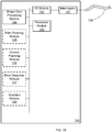
- FIG. 1B shows an exemplary embodiment of processor 140 for processing the measurement data from a fiber optic shape sensor 120.
- instructions and modules used in any one of, or any combination of operations described with respect to processor 140 can be implemented in a wide variety of software and/or hardware architectures, such as software code modules running on dedicated processors, application specific integrated circuits (ASICs), field programmable gate arrays (FPGAs), or any other logic implementation, alone or in any combination.
- ASICs application specific integrated circuits
- FPGAs field programmable gate arrays
- Processor 140 in FIG. 1B includes an interrogator 141, an input/output module 142, a processor module 143, and a shape data processing module 144.
- Interrogator 141 interrogates the optical fiber of shape sensor 120 and provides shape information to input/output module 142.
- Processor module 143 then processes the information from input/output module 142 using a shape data processing module 144 (e.g., stored in memory within processor 140).
- the generated shape information for needle 110 can then be used to model the in-situ pose and/or shape of needle 110.
- known reference frame data e.g., the position and orientation of actuator 130/proximal end region of needle 110
- shape information for needle 110 can be combined with the shape information for needle 110 to determine the in-situ pose and/or shape.
- positional measurements taken of needle 110 e.g., via additional sensors on needle 110 or through visualization tracking
- shape data from shape sensor 120 can be used with the shape data from shape sensor 120 to determine the in-situ pose and/or shape. More detailed description of an exemplary pose-determination process is provided in copending and commonly assigned U.S. patent application publications 2009324161 and 2011119023 .
- processor 140 can include optional additional processing modules to make use of the shape data provided by shape sensor 120.
- an optional path planning module 145 can be included to identify an appropriate trajectory (or multiple trajectory options) for either fully- or semi-automated control or for providing guidance for manual control over system 100.
- an optional control planning module 146 can be included to generate the appropriate control signals for actuator 130, for example based on the output of path planning module 145.
- an optional error detection module 147 can be included to compare measured shape, pose, and/or position data against expected values (e.g., desired values or values predicted from a mathematical model). For example, in some embodiments, the measured data can be compared against model data to validate and/or update the model data. In other embodiments, the measured data can be compared to target data (e.g., comparing actual trajectory of needle 110 to a desired trajectory) to avoid excessive deviation from a desired behavior. In some embodiments, such error detection can provide notification to the surgeon via visual, aural, or tactile cues or reports. In various other embodiments, deviations can be presented graphically (e.g., on a video monitor, overlaying actual trajectory onto desired trajectory). In such embodiments, an optional graphics module 148 can also be included in processor 140 to provide the necessary graphical representation of the measurements of shape sensor 120. In other embodiments, graphics module 148 can be included simply to provide a visual representation of the shape data measured by shape sensor 120.
- expected values e.g., desired values or values predicted from
- a surgical procedure can be beneficially enhanced by measuring the shape of a steerable needle and then controlling the needle (e.g., adjusting the shape of the needle, changing the orientation of the needle (e.g., axial rotation), advancing/retracting the needle, etc.) based on that measured shape.
- the same methods and procedures can be use in animals (e.g., veterinary use), cadavers, artificial anatomic replicas, and/or computer simulations of surgical procedures.
- FIG. 4 shows an exemplary flow diagram for the use of shape sensing in such a procedure.
- a Shape Measurement step 410 the shape of a steerable flexible needle (such as needle 110 described above) is measured.
- the measurement can be performed using any type of shape sensor capable of providing real time shape information for the flexible needle (such as shape sensor 120 described above).
- shape sensor 120 capable of providing real time shape information for the flexible needle.
- the measured data is used to model the actual shape of the flexible needle.
- step 420 may simply involve determining the standalone shape of the needle - for example to determine if the needle has reached a desired deployed state.
- step 420 can involve determining the shape of the needle along with its orientation (e.g., using additional reference frame information from the proximal (attachment) region of the needle to the actuator (such as actuator 130, above), or from additional sensor data (such as sensor 315 above)).
- FIG. 5 shows an embodiment of the flow diagram of FIG. 4 that includes an optional Pose Modeling step 522.
- step 420 can provide a significant procedural advantage over approaches limited to the use of catheters having a single position sensor (or several discrete sensors at particular locations), which can only estimate shape and orientation by assuming perfect mechanical transfer between the inputs and the measured locations.
- the actual shape measurements of step 420 can allow total insertion depth of the needle to be accurately determined, along with distal tip position and orientation. This determination can be made regardless of the torsional and axial flexibility of the needle and any effects of friction and normal forces between the needle and the patient tissue, which would otherwise need to be precisely modeled to produce similar results using a discrete sensor system - an unwieldy and likely unmanageable approach for most surgical applications.
- step 420 can include the identification or refinement of model parameters in a biomechanical model of the tissue and/or kinematic model of the needle system, as indicated by optional Adjust Model Parameters step 523 in FIG. 5 .
- the actual behavior of the needle e.g., bend radius
- material e.g., diseased or degenerative tissue regions exhibiting unexpected material properties, such as tumors, cysts, osteoporosis, etc.
- the actual needle trajectory can be used to estimate and update kinematic mapping between the actuator inputs and the actual needle movement (e.g., the tip and/or the shaft of the needle), thereby improving the responsiveness and accuracy of the needle control.
- the actual needle trajectory can be used to calculate loading of the needle, at discrete locations or along its entire length, since the curvature(s) of the needle will be dependent at least in part on the local forces applied to the needle.
- the pose information determinable in step 420 can be beneficially used to indicate or visualize the actual placement of the needle within a patient or the actual surgical trajectory being followed by the needle, as in an optional Path Modeling step 430.
- step 430 can include using the needle shape information determined in step 420 to determine one or more target trajectories for the continuing advance of the needle (e.g., based on needle properties, anatomical model properties, needle behavior up to current location, supplemental anatomical information (e.g., visualization, enhanced material properties based on actuation force required by needle, etc.), and/or any other path-affecting information), as indicated by an optional Path Planning step 531 in FIG. 5 .
- steps 420 and/or 430 can include comparing the actual needle shape and/or trajectory with an expected or desired shape/trajectory. Any deviation from the desired shape/trajectory can be identified and/or used to provide feedback to the surgeon as to potential corrective actions, depending on the magnitude of the deviation.
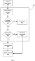
- FIG. 6 shows a flow diagram in which step 420 includes an optional Detect Shape Deviation step 621 in which the measured shape is compared to an expected shape. The deviation can then be assessed in an Exceeds Threshold? step 622, where if the deviation is greater than some preset limit, a notification is provided in an Error State step 623.
- This notification can take any form, including a visual warning, an audible warning, an error message, a tactile indication, warning icon, and/or system freeze/recovery action, among others.
- step 623 can result in procedure abort or restart, due to excessive needle deformation.
- a determination is made in an optional Correction Required? step 624, wherein if the deviation is small enough, no adjustment to the needle shape is made, and the process simply continues. However, if the deviation is determined to require correction, such correction can be calculated in a Determine Adjustment step 625. This adjustment can be provided to the surgeon as instructions, graphical representation, or any other means for conveying the information to the surgeon, or can be provided automatically to the system to cause automatic correction of the needle shape (e.g., providing appropriate control signals to the needle actuator).
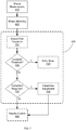
- FIG. 7 shows a flow diagram in which step 430 includes an optional Detect Path Deviation step 731 in which the measured needle trajectory is compared to an expected trajectory (e.g., a pre-operatively determined trajectory or an intraoperatively modeled trajectory). The deviation can then be assessed in an Exceeds Threshold? step 732, where if the deviation is greater than some preset limit, a notification is provided in an Error State step 733.
- This notification can take any form, including a visual warning, an audible warning, an error message, a tactile indication, warning icon, and/or system freeze/recovery action, among others.
- step 733 can result in procedure abort or restart, due to excessive trajectory deviation.
- the shape and/or position of the needle can also be adjusted in an optional Needle Control step 440.
- the shape and/or path information derived from step 420 and optional step 430, respectively can be used to determine the appropriate advancement/retraction and/or shape adjustment for the needle. For instance, if steps 420 and/or 420 indicate that the needle shape is sub-optimal for completion of the desired procedure, the needle can be adjusted towards a more optimized shape in step 440 (e.g., by actively changing the needle shape, by changing the needle orientation to cause the desired shape change during advancement/retraction, and/or by performing any other shape-affecting action).
- the needle can be adjusted towards a more optimized path in step 440 (e.g., by changing needle shape, by changing the needle orientation (e.g., rotation), retracting the needle, and/or any other trajectory-impacting action).
- this shape and/or trajectory adjustment can be performed manually, in response to surgeon cues (e.g., visual indication of deviation, sounds, or tactile indications when a deviation from the desired path is detected), automatically, or any combination of the above.
- the specific controls applied to the needle actuator can be determined based on the shape sensor data, as indicated by an optional Control Planning step 532 in FIG. 5 .
Landscapes
- Health & Medical Sciences (AREA)
- Life Sciences & Earth Sciences (AREA)
- Surgery (AREA)
- Engineering & Computer Science (AREA)
- Animal Behavior & Ethology (AREA)
- General Health & Medical Sciences (AREA)
- Biomedical Technology (AREA)
- Heart & Thoracic Surgery (AREA)
- Medical Informatics (AREA)
- Molecular Biology (AREA)
- Veterinary Medicine (AREA)
- Public Health (AREA)
- Pathology (AREA)
- Nuclear Medicine, Radiotherapy & Molecular Imaging (AREA)
- Human Computer Interaction (AREA)
- Physics & Mathematics (AREA)
- Biophysics (AREA)
- Robotics (AREA)
- Surgical Instruments (AREA)
- Endoscopes (AREA)
Claims (15)
- Aiguille flexible (110) comprenant :un corps d'aiguille allongé flexible ayant une lumière d'aiguille s'étendant à l'intérieur de celui-ci, le corps d'aiguille allongé incluant une région distale configurée pour percer ou réaliser un trou dans un tissu cible ;un capteur de forme (120) couplé au corps d'aiguille allongé ; etun connecteur adapté pour connecter le capteur de forme (120) à un processeur (140) pour déterminer la forme du corps d'aiguille flexible allongé sur la base de données provenant du capteur de forme (120).
- Aiguille flexible (110) selon la revendication 1, où le capteur de forme (120) comprend au moins l'un parmi une fibre optique ayant un réseau de Bragg sur fibre, un fil de nitinol, et un élément piézorésistif, ou
où le corps d'aiguille allongé flexible inclut une paroi (110W) définissant une lumière intérieure (112A), où le capteur de forme (120) peut être inséré de manière amovible dans la lumière intérieure (112A), ou
où le corps d'aiguille allongé flexible inclut une paroi (110W) ayant une surface intérieure et une surface extérieure, la surface intérieure définissant une lumière intérieure (111),
où une seconde lumière (112A) est définie entre la surface intérieure et la surface extérieure, et
où le capteur de forme (120) est positionné au moins partiellement à l'intérieur de la seconde lumière (112A), ou
où le corps d'aiguille allongé flexible inclut une pluralité de segments incurvés concentriques (210A-D), où chacun des différents segments incurvés concentriques (210AD) peut indépendamment tourner et s'étendre et où un segment le plus distal des différents segments incurvés concentriques (210A-D) inclut la région distale configurée pour percer ou réaliser un trou dans un tissu cible, ou
comprenant en outre au moins un câble de commande (215), où une flexion du corps d'aiguille allongé flexible est commandée par le câble de commande (215), ou
où la région de pointe distale comprend l'une parmi une pointe conique, une pointe incurvée, et une pointe solide que se termine en un point configuré pour percer ou réaliser un trou dans un tissu cible, ou
comprenant en outre un second capteur de forme (120-2), au moins une partie du second capteur de forme (120-2) étant sensiblement parallèle à au moins une partie du capteur de forme (120), où le connecteur est en outre adapté pour connecter le second capteur de forme (120-2), au processeur (140) pour déterminer la forme de l'aiguille flexible (110) sur la base de données provenant du capteur de forme (120) et du second capteur de forme (120-2), ou
comprenant en outre un capteur de position (315), où le connecteur est en outre adapté pour connecter le capteur de position (315) au processeur (140) pour déterminer une position d'une section de l'aiguille flexible (110) sur la base de données provenant du capteur de position (315). - Aiguille flexible (110) selon la revendication 1, où le corps d'aiguille allongé flexible inclut une paroi (110W) définissant la lumière d'aiguille, où le capteur de forme (120) est fixé à la paroi (110W), et de préférence
où le capteur de forme (120) est fixé à une surface externe de la paroi (110W), et de préférence
où le capteur de forme (120) est fixé à une surface interne de la paroi (110W). - Aiguille flexible (110) selon la revendication 3, où la paroi (110W) comprend une rainure (112B, C), et où le capteur de forme (120) est au moins partiellement positionné à l'intérieur de la rainure (112B, C), et de préférence
où la rainure (112B, C) comprend une ou plusieurs caractéristiques de positionnement (121A-C) en correspondance avec le capteur de forme (120) et où la ou les caractéristiques de positionnement (121A-C) empêchent un mouvement du capteur de forme (120) le long de la rainure (112B, C), et de préférence
où la ou les caractéristiques de positionnement (121A-C) comprennent au moins l'une parmi une fente, une crête, et une section filetée. - Système chirurgical (100) comprenant :une aiguille flexible (110) selon l'une quelconque des revendications 1 à 4 ; etun actionneur (130) pour manipuler l'aiguille flexible (110).
- Système chirurgical selon la revendication 5, incluant en outre le processeur (140) pour déterminer une forme de l'aiguille flexible (110) sur la base de données provenant du capteur de forme (120).
- Système chirurgical selon la revendication 5, où le corps d'aiguille allongé flexible de l'aiguille flexible comprend une paroi (110W) définissant une lumière intérieure (112A) et où le capteur de forme (120) peut être inséré de manière amovible dans la lumière intérieure (112A) et où le capteur de forme (120) comprend un stylet dont la taille est adaptée pour une insertion à l'intérieur de la lumière intérieure (112A).
- Système chirurgical selon la revendication 5, où le corps d'aiguille allongé flexible de l'aiguille flexible (110) comprend une paroi (110W) définissant la lumière d'aiguille du corps d'aiguille allongé flexible, et
où le capteur de forme (120) est fixé à la paroi (110W),
où la rainure (112B, C) comprend une ou plusieurs caractéristiques de positionnement (121A-C) en correspondance avec le capteur de forme (120),
où la ou les caractéristiques de positionnement (121A-C) empêchent un mouvement du capteur de forme (120) le long de la rainure (112B, C), et
où la ou les caractéristiques de positionnement (121A-C) comprennent au moins l'une parmi une fente, une crête, et une section filetée. - Système chirurgical selon la revendication 5, où l'aiguille flexible (110) comprend une pointe d'aiguille solide.
- Système chirurgical selon la revendication 5, comprenant en outre un second capteur de forme (120-2), au moins une partie du second capteur de forme (120-2) étant sensiblement parallèle à au moins une partie du capteur de forme (120), où le connecteur est en outre adapté pour connecter le second capteur de forme (120-2) au processeur (140) pour déterminer la forme de l'aiguille flexible (110) sur la base de données provenant du capteur de forme (120) et du second capteur de forme (120-2), et où chacun du capteur de forme (120) et du second capteur de forme (120) est fixé à différents segments incurvés concentriques (210A-D) du corps d'aiguille allongé flexible.
- Système chirurgical selon la revendication 5, comprenant en outre un capteur de position (315) fixé à une section de l'aiguille flexible (110), le processeur (140) étant configuré pour déterminer une position de la section sur la base de données provenant du capteur de position (315).
- Système chirurgical selon la revendication 11, où le capteur de position (315) est fixé à une pointe distale de l'aiguille flexible (110).
- Système chirurgical selon la revendication 12, comprenant en outre un dispositif de commande manuel permettant une commande directe par l'utilisateur sur l'actionneur (130).
- Système chirurgical selon la revendication 5, comprenant en outre une plate-forme de chirurgie robotique couplée à l'actionneur (130).
- Système chirurgical selon la revendication 5, où l'aiguille flexible (110) est une aiguille de biopsie transcutanée, ou une aiguille de biopsie endoscopique, ou est adaptée pour administrer un dispositif d'ablation de tissu, ou est adaptée pour administrer des grains radioactifs.
Priority Applications (1)
| Application Number | Priority Date | Filing Date | Title |
|---|---|---|---|
| EP18215883.2A EP3488803B1 (fr) | 2012-02-03 | 2013-01-28 | Aiguille orientable flexible avec détection de forme intégrée |
Applications Claiming Priority (3)
| Application Number | Priority Date | Filing Date | Title |
|---|---|---|---|
| US201261594959P | 2012-02-03 | 2012-02-03 | |
| US201261599015P | 2012-02-15 | 2012-02-15 | |
| PCT/US2013/023398 WO2013116140A1 (fr) | 2012-02-03 | 2013-01-28 | Aiguille orientable flexible avec détection de la forme intégrée |
Related Child Applications (1)
| Application Number | Title | Priority Date | Filing Date |
|---|---|---|---|
| EP18215883.2A Division EP3488803B1 (fr) | 2012-02-03 | 2013-01-28 | Aiguille orientable flexible avec détection de forme intégrée |
Publications (3)
| Publication Number | Publication Date |
|---|---|
| EP2809249A1 EP2809249A1 (fr) | 2014-12-10 |
| EP2809249A4 EP2809249A4 (fr) | 2015-07-22 |
| EP2809249B1 true EP2809249B1 (fr) | 2018-12-26 |
Family
ID=48903497
Family Applications (2)
| Application Number | Title | Priority Date | Filing Date |
|---|---|---|---|
| EP13743290.2A Active EP2809249B1 (fr) | 2012-02-03 | 2013-01-28 | Aiguille orientable flexible avec détection de la forme intégrée |
| EP18215883.2A Active EP3488803B1 (fr) | 2012-02-03 | 2013-01-28 | Aiguille orientable flexible avec détection de forme intégrée |
Family Applications After (1)
| Application Number | Title | Priority Date | Filing Date |
|---|---|---|---|
| EP18215883.2A Active EP3488803B1 (fr) | 2012-02-03 | 2013-01-28 | Aiguille orientable flexible avec détection de forme intégrée |
Country Status (4)
| Country | Link |
|---|---|
| US (5) | US9636040B2 (fr) |
| EP (2) | EP2809249B1 (fr) |
| JP (2) | JP6290099B2 (fr) |
| WO (1) | WO2013116140A1 (fr) |
Cited By (3)
| Publication number | Priority date | Publication date | Assignee | Title |
|---|---|---|---|---|
| US20230417998A1 (en) * | 2022-06-24 | 2023-12-28 | Bard Access Systems, Inc. | Shape Sensing Fiber Optic Tip Protection Systems and Devices |
| US12564340B2 (en) | 2022-07-12 | 2026-03-03 | Bard Access Systems, Inc. | Eccentric single-core fiber-optic enabled medical device |
| US12605116B2 (en) | 2022-04-11 | 2026-04-21 | Bard Access Systems, Inc. | Fiber optic medical systems and devices with electrical tip |
Families Citing this family (250)
| Publication number | Priority date | Publication date | Assignee | Title |
|---|---|---|---|---|
| US8218847B2 (en) | 2008-06-06 | 2012-07-10 | Superdimension, Ltd. | Hybrid registration method |
| US9254123B2 (en) | 2009-04-29 | 2016-02-09 | Hansen Medical, Inc. | Flexible and steerable elongate instruments with shape control and support elements |
| US8672837B2 (en) | 2010-06-24 | 2014-03-18 | Hansen Medical, Inc. | Methods and devices for controlling a shapeable medical device |
| US8827948B2 (en) | 2010-09-17 | 2014-09-09 | Hansen Medical, Inc. | Steerable catheters |
| US9119655B2 (en) | 2012-08-03 | 2015-09-01 | Stryker Corporation | Surgical manipulator capable of controlling a surgical instrument in multiple modes |
| EP2809249B1 (fr) * | 2012-02-03 | 2018-12-26 | Intuitive Surgical Operations, Inc. | Aiguille orientable flexible avec détection de la forme intégrée |
| US20130245640A1 (en) * | 2012-03-15 | 2013-09-19 | Civco Medical Instruments Co., Inc. | Device and system for narrow gauge medical instrument navigation |
| WO2013192598A1 (fr) * | 2012-06-21 | 2013-12-27 | Excelsius Surgical, L.L.C. | Plateforme de robot chirurgical |
| CN119097419A (zh) | 2012-08-03 | 2024-12-10 | 史赛克公司 | 用于机器人外科手术的系统和方法 |
| US9820818B2 (en) * | 2012-08-03 | 2017-11-21 | Stryker Corporation | System and method for controlling a surgical manipulator based on implant parameters |
| US9226796B2 (en) | 2012-08-03 | 2016-01-05 | Stryker Corporation | Method for detecting a disturbance as an energy applicator of a surgical instrument traverses a cutting path |
| EP2908733B1 (fr) | 2012-10-17 | 2020-07-29 | Worcester Polytechnic Institute | Système de commande sous-actionnée de trajet d'introduction pour aiguilles à pointe asymétrique |
| US10149720B2 (en) | 2013-03-08 | 2018-12-11 | Auris Health, Inc. | Method, apparatus, and a system for facilitating bending of an instrument in a surgical or medical robotic environment |
| US9057600B2 (en) | 2013-03-13 | 2015-06-16 | Hansen Medical, Inc. | Reducing incremental measurement sensor error |
| US20140277334A1 (en) | 2013-03-14 | 2014-09-18 | Hansen Medical, Inc. | Active drives for robotic catheter manipulators |
| US9014851B2 (en) | 2013-03-15 | 2015-04-21 | Hansen Medical, Inc. | Systems and methods for tracking robotically controlled medical instruments |
| US9629595B2 (en) | 2013-03-15 | 2017-04-25 | Hansen Medical, Inc. | Systems and methods for localizing, tracking and/or controlling medical instruments |
| US9271663B2 (en) | 2013-03-15 | 2016-03-01 | Hansen Medical, Inc. | Flexible instrument localization from both remote and elongation sensors |
| US10376672B2 (en) | 2013-03-15 | 2019-08-13 | Auris Health, Inc. | Catheter insertion system and method of fabrication |
| US11020016B2 (en) | 2013-05-30 | 2021-06-01 | Auris Health, Inc. | System and method for displaying anatomy and devices on a movable display |
| KR102356881B1 (ko) | 2013-08-15 | 2022-02-03 | 인튜어티브 서지컬 오퍼레이션즈 인코포레이티드 | 카테터 위치설정 및 삽입을 위한 그래픽 사용자 인터페이스 |
| US9974617B2 (en) * | 2013-09-30 | 2018-05-22 | Koninklijke Philips N.V. | Multipurpose lumen design for optical shape sensing |
| CN105939647B (zh) * | 2013-10-24 | 2020-01-21 | 奥瑞斯健康公司 | 机器人辅助腔内外科手术系统及相关方法 |
| WO2015066164A1 (fr) | 2013-10-31 | 2015-05-07 | Boston Scientific Scimed, Inc. | Dispositif médical pour une cartographie à haute résolution à l'aide d'une correspondance localisée |
| CN105636514B (zh) | 2013-11-01 | 2020-06-05 | 波士顿科学医学有限公司 | 使用延迟内插的心脏标测 |
| WO2015071343A1 (fr) * | 2013-11-13 | 2015-05-21 | Koninklijke Philips N.V. | Détection d'angle de rotation d'un dispositif d'intervention |
| WO2015088961A1 (fr) * | 2013-12-13 | 2015-06-18 | Intuitive Surgical Operations, Inc. | Stylet de capteur |
| CN114366181B (zh) | 2013-12-13 | 2024-08-02 | 直观外科手术操作公司 | 伸缩式活检针 |
| EP3107473A4 (fr) * | 2014-02-17 | 2017-10-04 | Asymmetric Medical Ltd. | Dispositifs de traitement et indications en temps réel |
| US11067387B2 (en) | 2014-02-28 | 2021-07-20 | Koninklijke Philips N.V. | Adaptive instrument kinematic model optimization for optical shape sensed instruments |
| WO2015132787A1 (fr) * | 2014-03-04 | 2015-09-11 | Xact Robotics Ltd. | Procédé de planification dynamique pour insertion d'aiguille |
| WO2015134276A1 (fr) | 2014-03-07 | 2015-09-11 | Boston Scientific Scimed, Inc. | Dispositifs médicaux pour le mappage de tissu cardiaque |
| US9687167B2 (en) | 2014-03-11 | 2017-06-27 | Boston Scientific Scimed, Inc. | Medical devices for mapping cardiac tissue |
| EP2923669B1 (fr) | 2014-03-24 | 2017-06-28 | Hansen Medical, Inc. | Systèmes et dispositifs pour le guidage instinctif d'un cathéter |
| US10779803B2 (en) | 2014-04-02 | 2020-09-22 | Intuitive Surgical Operations, Inc. | Devices, systems, and methods using a steerable stylet and flexible needle |
| US10792464B2 (en) | 2014-07-01 | 2020-10-06 | Auris Health, Inc. | Tool and method for using surgical endoscope with spiral lumens |
| US9561083B2 (en) | 2014-07-01 | 2017-02-07 | Auris Surgical Robotics, Inc. | Articulating flexible endoscopic tool with roll capabilities |
| US9744335B2 (en) | 2014-07-01 | 2017-08-29 | Auris Surgical Robotics, Inc. | Apparatuses and methods for monitoring tendons of steerable catheters |
| US9633431B2 (en) | 2014-07-02 | 2017-04-25 | Covidien Lp | Fluoroscopic pose estimation |
| US9603668B2 (en) | 2014-07-02 | 2017-03-28 | Covidien Lp | Dynamic 3D lung map view for tool navigation inside the lung |
| CN107072470B (zh) | 2014-09-02 | 2020-06-05 | 皇家飞利浦有限公司 | 用于光学形状感测的导丝 |
| JP6736544B2 (ja) * | 2014-09-09 | 2020-08-05 | インテュイティブ サージカル オペレーションズ, インコーポレイテッド | 異なる可撓性のガイド及びツールを備えるシステム |
| WO2016038496A1 (fr) * | 2014-09-11 | 2016-03-17 | Koninklijke Philips N.V. | Dispositif d'interface de capteur fournissant un traitement numérique de données d'écoulement et de pression intravasculaires |
| US10314463B2 (en) | 2014-10-24 | 2019-06-11 | Auris Health, Inc. | Automated endoscope calibration |
| CN107106119A (zh) | 2014-10-30 | 2017-08-29 | 皇家飞利浦有限公司 | 弯曲结构的超声可视化 |
| US9974525B2 (en) | 2014-10-31 | 2018-05-22 | Covidien Lp | Computed tomography enhanced fluoroscopic system, device, and method of utilizing the same |
| EP3220841B1 (fr) | 2014-11-19 | 2023-01-25 | EPiX Therapeutics, Inc. | Cartographie haute résolution de tissus avec stimulation cardiaque |
| AU2015349961A1 (en) | 2014-11-19 | 2017-06-29 | Epix Therapeutics, Inc. | Ablation devices, systems and methods of using a high-resolution electrode assembly |
| JP6825789B2 (ja) | 2014-11-19 | 2021-02-03 | エピックス セラピューティクス,インコーポレイテッド | 組織の高分解能マッピングのためのシステムおよび方法 |
| JP6734282B2 (ja) * | 2015-01-22 | 2020-08-05 | コーニンクレッカ フィリップス エヌ ヴェKoninklijke Philips N.V. | 予め組み込まれた又は取り外し可能な光学形状検知アタッチメントによるエンドグラフトの視覚化 |
| PL3064251T3 (pl) * | 2015-03-06 | 2020-06-29 | Mt.Derm Gmbh | Przyrząd nakłuwający skórę do miejscowego nakłuwania skóry człowieka lub zwierzęcia oraz urządzenie ręczne |
| US9636164B2 (en) | 2015-03-25 | 2017-05-02 | Advanced Cardiac Therapeutics, Inc. | Contact sensing systems and methods |
| US11819636B2 (en) | 2015-03-30 | 2023-11-21 | Auris Health, Inc. | Endoscope pull wire electrical circuit |
| US10317196B2 (en) * | 2015-06-17 | 2019-06-11 | The Charles Stark Draper Laboratory, Inc. | Navigation systems and methods using fiber optic shape sensors and localized position sensors |
| JP6739454B2 (ja) * | 2015-06-24 | 2020-08-12 | コーニンクレッカ フィリップス エヌ ヴェKoninklijke Philips N.V. | Forsデータを使用して膨張式医療器具を追跡し、その特性を判定するためのシステム及び方法 |
| JP6446550B2 (ja) * | 2015-07-10 | 2018-12-26 | オリンパス株式会社 | 可撓管挿入装置、及び可撓管挿入装置の作動方法 |
| US10702226B2 (en) | 2015-08-06 | 2020-07-07 | Covidien Lp | System and method for local three dimensional volume reconstruction using a standard fluoroscope |
| US10716525B2 (en) | 2015-08-06 | 2020-07-21 | Covidien Lp | System and method for navigating to target and performing procedure on target utilizing fluoroscopic-based local three dimensional volume reconstruction |
| US10674982B2 (en) | 2015-08-06 | 2020-06-09 | Covidien Lp | System and method for local three dimensional volume reconstruction using a standard fluoroscope |
| US20170042565A1 (en) * | 2015-08-11 | 2017-02-16 | Summit Medical Products, Inc. | Cannula guided surgical tool |
| AU2016321332B2 (en) | 2015-09-09 | 2020-10-08 | Auris Health, Inc. | Instrument device manipulator for a surgical robotics system |
| AU2016323982A1 (en) | 2015-09-18 | 2018-04-12 | Auris Health, Inc. | Navigation of tubular networks |
| US10575754B2 (en) | 2015-09-23 | 2020-03-03 | Covidien Lp | Catheter having a sensor and an extended working channel |
| EP3355780B1 (fr) * | 2015-10-02 | 2025-07-30 | Koninklijke Philips N.V. | Raccord pour navigation de dispositif à fil-guide de détection de forme optique |
| US10799280B2 (en) * | 2015-10-22 | 2020-10-13 | Medtronic Cryocath Lp | Post ablation tissue analysis technique |
| US10639108B2 (en) | 2015-10-30 | 2020-05-05 | Auris Health, Inc. | Process for percutaneous operations |
| US9955986B2 (en) | 2015-10-30 | 2018-05-01 | Auris Surgical Robotics, Inc. | Basket apparatus |
| US9949749B2 (en) | 2015-10-30 | 2018-04-24 | Auris Surgical Robotics, Inc. | Object capture with a basket |
| US10143526B2 (en) | 2015-11-30 | 2018-12-04 | Auris Health, Inc. | Robot-assisted driving systems and methods |
| EP3389539B1 (fr) | 2015-12-15 | 2020-05-20 | Koninklijke Philips N.V. | Système d'aide à la navigation |
| WO2017115235A1 (fr) * | 2015-12-29 | 2017-07-06 | Koninklijke Philips N.V. | Planification de trajectoire adaptative fondée sur image pour robot |
| EP3397186B1 (fr) * | 2015-12-29 | 2025-10-29 | Koninklijke Philips N.V. | Ablation convergente robotique guidée par image |
| JP6701232B2 (ja) * | 2016-01-08 | 2020-05-27 | オリンパス株式会社 | マニピュレータシステムとその駆動方法 |
| SG11201807618QA (en) | 2016-03-15 | 2018-10-30 | Epix Therapeutics Inc | Improved devices, systems and methods for irrigated ablation |
| CN108135583B (zh) * | 2016-05-31 | 2022-07-15 | 直观外科手术操作公司 | 顺从性活检针系统 |
| KR20190015581A (ko) * | 2016-06-30 | 2019-02-13 | 인튜어티브 서지컬 오퍼레이션즈 인코포레이티드 | 의료용 로봇 시스템의 결함 반응 메커니즘을 위한 시스템 및 방법 |
| EP4374768B1 (fr) * | 2016-06-30 | 2026-03-25 | Intuitive Surgical Operations, Inc. | Interface utilisateur graphique pour afficher des informations de guidage dans une pluralité de modes pendant une procédure guidée par image |
| EP4238490B1 (fr) * | 2016-06-30 | 2025-09-17 | Intuitive Surgical Operations, Inc. | Interface utilisateur graphique pour l'affichage d'informations de guidage pendant une intervention guidée par imagerie |
| WO2018024322A1 (fr) * | 2016-08-02 | 2018-02-08 | Brainlab Ag | Vérification de modèle de déformation à joint solide |
| WO2018035122A1 (fr) * | 2016-08-16 | 2018-02-22 | Intuitive Surgical Operations, Inc. | Précision augmentée à l'aide d'une fibre de forme de grand diamètre |
| CN109561934B (zh) * | 2016-08-23 | 2022-03-08 | 直观外科手术操作公司 | 用于医疗程序期间监测患者运动的系统和方法 |
| US10463439B2 (en) | 2016-08-26 | 2019-11-05 | Auris Health, Inc. | Steerable catheter with shaft load distributions |
| EP3506836B1 (fr) | 2016-08-31 | 2024-10-02 | Auris Health, Inc. | Rallonge pour instrument chirurgical |
| EP4623797A3 (fr) * | 2016-09-21 | 2025-12-03 | Intuitive Surgical Operations, Inc. | Systèmes et procédés de détection de flambage d'instrument |
| US9931025B1 (en) | 2016-09-30 | 2018-04-03 | Auris Surgical Robotics, Inc. | Automated calibration of endoscopes with pull wires |
| WO2018096491A1 (fr) * | 2016-11-28 | 2018-05-31 | Koninklijke Philips N.V. | Détection de forme de multiples dispositifs sur fil |
| WO2018104162A1 (fr) | 2016-12-05 | 2018-06-14 | Koninklijke Philips N.V. | Systèmes et procédés pour la détermination de la longueur d'un dispositif d'intervention dont la forme n'est pas détectée à l'aide d'un fil-guide dont la forme est détectée et pour la détermination de l'état du fil-guide par rapport à un dispositif d'intervention |
| WO2018122946A1 (fr) | 2016-12-27 | 2018-07-05 | オリンパス株式会社 | Procédé d'acquisition de forme et procédé de commande de manipulateur médical |
| US10244926B2 (en) | 2016-12-28 | 2019-04-02 | Auris Health, Inc. | Detecting endolumenal buckling of flexible instruments |
| EP3562423A1 (fr) * | 2016-12-28 | 2019-11-06 | Auris Health, Inc. | Appareil d'insertion d'instrument souple |
| JP7167030B2 (ja) * | 2017-01-03 | 2022-11-08 | コーニンクレッカ フィリップス エヌ ヴェ | 形状検知デバイスを使用した医療ナビゲーションシステム及びその動作方法 |
| KR102015520B1 (ko) * | 2017-01-13 | 2019-08-28 | 주식회사 루트로닉 | 치료장치 및 이의 제어방법 |
| US11529190B2 (en) | 2017-01-30 | 2022-12-20 | Covidien Lp | Enhanced ablation and visualization techniques for percutaneous surgical procedures |
| KR102116164B1 (ko) * | 2017-02-03 | 2020-05-27 | 재단법인 아산사회복지재단 | 카테터의 센싱 정보를 이용한 심장의 3차원 매핑 시스템 및 방법 |
| US11793579B2 (en) | 2017-02-22 | 2023-10-24 | Covidien Lp | Integration of multiple data sources for localization and navigation |
| EP3595537B1 (fr) * | 2017-03-16 | 2026-01-21 | Boston Scientific Scimed, Inc. | Aiguille de biopsie permettant d'accéder à des nodules pulmonaires périphériques |
| CN110636814A (zh) * | 2017-03-21 | 2019-12-31 | 皇家飞利浦有限公司 | Oss引导和监测系统、控制器以及方法 |
| JP7282685B2 (ja) | 2017-03-31 | 2023-05-29 | オーリス ヘルス インコーポレイテッド | 生理学的ノイズを補償する管腔ネットワークのナビゲーション用ロボットシステム |
| US12140487B2 (en) | 2017-04-07 | 2024-11-12 | Bard Access Systems, Inc. | Optical fiber-based medical device tracking and monitoring system |
| EP4539056A3 (fr) | 2017-04-18 | 2025-06-25 | Intuitive Surgical Operations, Inc. | Interface utilisateur graphique pour planifier une procédure |
| US11937880B2 (en) | 2017-04-18 | 2024-03-26 | Intuitive Surgical Operations, Inc. | Graphical user interface for monitoring an image-guided procedure |
| WO2018200865A1 (fr) | 2017-04-27 | 2018-11-01 | Epix Therapeutics, Inc. | Détermination de la nature d'un contact entre une pointe de cathéter et un tissu |
| AU2018265018B2 (en) | 2017-05-12 | 2024-03-07 | Auris Health, Inc. | Biopsy apparatus and system |
| CN110769736B (zh) | 2017-05-17 | 2023-01-13 | 奥瑞斯健康公司 | 可更换工作通道 |
| US10575907B2 (en) | 2017-06-21 | 2020-03-03 | Biosense Webster (Israel) Ltd. | Registration with trajectory information with shape sensing |
| US10022192B1 (en) | 2017-06-23 | 2018-07-17 | Auris Health, Inc. | Automatically-initialized robotic systems for navigation of luminal networks |
| US11026758B2 (en) | 2017-06-28 | 2021-06-08 | Auris Health, Inc. | Medical robotics systems implementing axis constraints during actuation of one or more motorized joints |
| US10699448B2 (en) | 2017-06-29 | 2020-06-30 | Covidien Lp | System and method for identifying, marking and navigating to a target using real time two dimensional fluoroscopic data |
| US10426559B2 (en) | 2017-06-30 | 2019-10-01 | Auris Health, Inc. | Systems and methods for medical instrument compression compensation |
| US12004830B2 (en) | 2017-08-16 | 2024-06-11 | Intuitive Surgical Operations , Inc. | Systems and methods for monitoring patient motion during a medical procedure |
| US10145747B1 (en) | 2017-10-10 | 2018-12-04 | Auris Health, Inc. | Detection of undesirable forces on a surgical robotic arm |
| US10893843B2 (en) | 2017-10-10 | 2021-01-19 | Covidien Lp | System and method for identifying and marking a target in a fluoroscopic three-dimensional reconstruction |
| US11058493B2 (en) | 2017-10-13 | 2021-07-13 | Auris Health, Inc. | Robotic system configured for navigation path tracing |
| WO2019074786A1 (fr) * | 2017-10-13 | 2019-04-18 | Intuitive Surgical Operations, Inc. | Systèmes et procédés de détection de forces environnementales sur un dispositif allongé |
| US10555778B2 (en) | 2017-10-13 | 2020-02-11 | Auris Health, Inc. | Image-based branch detection and mapping for navigation |
| WO2019109211A1 (fr) * | 2017-12-04 | 2019-06-13 | Covidien Lp | Segmentation d'antenne d'ablation automatique à partir d'une image de tomodensitométrie |
| CN110831536B (zh) | 2017-12-06 | 2021-09-07 | 奥瑞斯健康公司 | 用于针对非命令器械滚转进行校正的系统和方法 |
| JP7322026B2 (ja) | 2017-12-14 | 2023-08-07 | オーリス ヘルス インコーポレイテッド | 器具の位置推定のシステムおよび方法 |
| EP3723619B1 (fr) | 2017-12-15 | 2025-04-16 | C. R. Bard, Inc. | Sonde de mesure d'impédance et appareil de biopsie |
| CN110809453B (zh) | 2017-12-18 | 2023-06-06 | 奥瑞斯健康公司 | 用于腔网络内的器械跟踪和导航的方法和系统 |
| US10992078B2 (en) | 2018-01-29 | 2021-04-27 | Bard Access Systems, Inc. | Connection system for establishing an electrical connection through a drape and methods thereof |
| US10930064B2 (en) | 2018-02-08 | 2021-02-23 | Covidien Lp | Imaging reconstruction system and method |
| US11364004B2 (en) | 2018-02-08 | 2022-06-21 | Covidien Lp | System and method for pose estimation of an imaging device and for determining the location of a medical device with respect to a target |
| US10905498B2 (en) | 2018-02-08 | 2021-02-02 | Covidien Lp | System and method for catheter detection in fluoroscopic images and updating displayed position of catheter |
| JP7301884B2 (ja) | 2018-02-13 | 2023-07-03 | オーリス ヘルス インコーポレイテッド | 医療用器具を駆動するためのシステム及び方法 |
| WO2019190657A1 (fr) | 2018-03-28 | 2019-10-03 | Auris Health, Inc. | Instruments médicaux ayant des profils variables de rigidité à la flexion |
| CN110913791B (zh) | 2018-03-28 | 2021-10-08 | 奥瑞斯健康公司 | 用于显示所估计的器械定位的系统和方法 |
| JP7214747B2 (ja) | 2018-03-28 | 2023-01-30 | オーリス ヘルス インコーポレイテッド | 位置センサの位置合わせのためのシステム及び方法 |
| US10872449B2 (en) | 2018-05-02 | 2020-12-22 | Covidien Lp | System and method for constructing virtual radial ultrasound images from CT data and performing a surgical navigation procedure using virtual ultrasound images |
| US10772696B2 (en) | 2018-05-18 | 2020-09-15 | Bard Access Systems, Inc. | Connection systems and methods thereof for establishing an electrical connection through a drape |
| MX2020012902A (es) | 2018-05-30 | 2021-02-26 | Auris Health Inc | Sistemas y metodos para la prediccion de ramificacion basada en sensores de ubicacion. |
| KR102455671B1 (ko) | 2018-05-31 | 2022-10-20 | 아우리스 헬스, 인코포레이티드 | 이미지-기반 기도 분석 및 매핑 |
| MX2020012897A (es) | 2018-05-31 | 2021-05-27 | Auris Health Inc | Sistemas roboticos y metodos para navegacion de la red luminal que detectan ruido fisiologico. |
| MX2020012898A (es) | 2018-05-31 | 2021-02-26 | Auris Health Inc | Navegacion de redes tubulares basada en trayecto. |
| CN108775981B (zh) * | 2018-06-12 | 2024-08-02 | 南昌大学 | 一种高精度的差动式膜片光纤压力传感系统 |
| EP3813632B1 (fr) | 2018-06-27 | 2026-04-22 | Auris Health, Inc. | Systèmes d'alignement et de fixation pour instruments médicaux |
| EP3821444A1 (fr) | 2018-07-10 | 2021-05-19 | Intuitive Surgical Operations, Inc. | Systèmes et procédés de détection d'outil et modes de commande associés |
| US11559298B2 (en) * | 2018-07-16 | 2023-01-24 | Cilag Gmbh International | Surgical visualization of multiple targets |
| US11705238B2 (en) | 2018-07-26 | 2023-07-18 | Covidien Lp | Systems and methods for providing assistance during surgery |
| US11071591B2 (en) | 2018-07-26 | 2021-07-27 | Covidien Lp | Modeling a collapsed lung using CT data |
| WO2020033318A1 (fr) | 2018-08-07 | 2020-02-13 | Auris Health, Inc. | Combinaison de détection de forme basée sur des contraintes avec commande de cathéter |
| WO2020068853A2 (fr) | 2018-09-26 | 2020-04-02 | Auris Health, Inc. | Articulation d'instruments médicaux |
| US10820947B2 (en) | 2018-09-28 | 2020-11-03 | Auris Health, Inc. | Devices, systems, and methods for manually and robotically driving medical instruments |
| EP4643806A3 (fr) | 2018-09-28 | 2026-01-14 | Auris Health, Inc. | Systèmes et procédés d'accueil d'instruments médicaux |
| CN119924988A (zh) | 2018-09-28 | 2025-05-06 | 奥瑞斯健康公司 | 用于伴随内窥镜和经皮医学规程的机器人系统和方法 |
| US11944388B2 (en) | 2018-09-28 | 2024-04-02 | Covidien Lp | Systems and methods for magnetic interference correction |
| CN113164117B (zh) | 2018-10-09 | 2024-12-20 | 新泽西州立罗格斯大学 | 经皮插管器械的超声引导对准与插入 |
| US11877806B2 (en) | 2018-12-06 | 2024-01-23 | Covidien Lp | Deformable registration of computer-generated airway models to airway trees |
| US11998284B2 (en) * | 2018-12-07 | 2024-06-04 | Acclarent, Inc. | Articulating guide with integral position sensor |
| US11045075B2 (en) | 2018-12-10 | 2021-06-29 | Covidien Lp | System and method for generating a three-dimensional model of a surgical site |
| US11617493B2 (en) | 2018-12-13 | 2023-04-04 | Covidien Lp | Thoracic imaging, distance measuring, surgical awareness, and notification system and method |
| US11801113B2 (en) | 2018-12-13 | 2023-10-31 | Covidien Lp | Thoracic imaging, distance measuring, and notification system and method |
| CN113286543A (zh) | 2018-12-28 | 2021-08-20 | 奥瑞斯健康公司 | 具有可关节运动区段的医疗器械 |
| US11357593B2 (en) | 2019-01-10 | 2022-06-14 | Covidien Lp | Endoscopic imaging with augmented parallax |
| US11625825B2 (en) | 2019-01-30 | 2023-04-11 | Covidien Lp | Method for displaying tumor location within endoscopic images |
| US11925333B2 (en) | 2019-02-01 | 2024-03-12 | Covidien Lp | System for fluoroscopic tracking of a catheter to update the relative position of a target and the catheter in a 3D model of a luminal network |
| US11564751B2 (en) | 2019-02-01 | 2023-01-31 | Covidien Lp | Systems and methods for visualizing navigation of medical devices relative to targets |
| US11744643B2 (en) | 2019-02-04 | 2023-09-05 | Covidien Lp | Systems and methods facilitating pre-operative prediction of post-operative tissue function |
| EP3705020A1 (fr) * | 2019-03-05 | 2020-09-09 | FBGS Technologies GmbH | Procédés et systèmes de détection de forme |
| CN113766868A (zh) | 2019-03-15 | 2021-12-07 | 直观外科手术操作公司 | 用于在医疗程序期间确定弯折和患者移动的系统 |
| US12478444B2 (en) | 2019-03-21 | 2025-11-25 | The Board Of Trustees Of The Leland Stanford Junior University | Systems and methods for localization based on machine learning |
| US11617627B2 (en) | 2019-03-29 | 2023-04-04 | Auris Health, Inc. | Systems and methods for optical strain sensing in medical instruments |
| US11819285B2 (en) | 2019-04-05 | 2023-11-21 | Covidien Lp | Magnetic interference detection systems and methods |
| US11975157B2 (en) | 2019-04-12 | 2024-05-07 | Covidien Lp | Method of manufacturing an elongated catheter having multiple sensors for three-dimensional location of the catheter |
| EP3962357B1 (fr) * | 2019-05-02 | 2024-01-17 | Fiagon GmbH | Kit chirurgical pour intervention chirurgicale rachidienne minimalement invasive |
| EP3989794A4 (fr) | 2019-06-28 | 2023-07-12 | Auris Health, Inc. | Introducteur de patient de système robotique |
| EP3997497B1 (fr) | 2019-07-29 | 2025-08-27 | Bard Access Systems, Inc. | Systèmes de connexion et procédés pour établir des connexions optiques et électriques à travers un champ |
| US12089902B2 (en) | 2019-07-30 | 2024-09-17 | Coviden Lp | Cone beam and 3D fluoroscope lung navigation |
| WO2021026502A1 (fr) | 2019-08-08 | 2021-02-11 | Bard Access Systems, Inc. | Modules de connecteur de fibres optiques comprenant des systèmes de détection de forme et procédés associés |
| CA3150788A1 (fr) | 2019-08-12 | 2021-02-18 | Bard Access Systems, Inc. | Systemes et procedes de detection de forme pour dispositifs medicaux |
| CN112386793A (zh) | 2019-08-12 | 2021-02-23 | 科利耳有限公司 | 在耳蜗内插入期间电极阵列姿态的实时估计 |
| US11896330B2 (en) | 2019-08-15 | 2024-02-13 | Auris Health, Inc. | Robotic medical system having multiple medical instruments |
| CN114554930A (zh) | 2019-08-15 | 2022-05-27 | 奥瑞斯健康公司 | 具有多个弯曲节段的医疗装置 |
| US12059281B2 (en) | 2019-08-19 | 2024-08-13 | Covidien Lp | Systems and methods of fluoro-CT imaging for initial registration |
| US11269173B2 (en) | 2019-08-19 | 2022-03-08 | Covidien Lp | Systems and methods for displaying medical video images and/or medical 3D models |
| CN114340542B (zh) | 2019-08-30 | 2023-07-21 | 奥瑞斯健康公司 | 用于位置传感器的基于权重的配准的系统和方法 |
| US11147633B2 (en) | 2019-08-30 | 2021-10-19 | Auris Health, Inc. | Instrument image reliability systems and methods |
| US11864935B2 (en) | 2019-09-09 | 2024-01-09 | Covidien Lp | Systems and methods for pose estimation of a fluoroscopic imaging device and for three-dimensional imaging of body structures |
| US11931111B2 (en) | 2019-09-09 | 2024-03-19 | Covidien Lp | Systems and methods for providing surgical guidance |
| US11627924B2 (en) | 2019-09-24 | 2023-04-18 | Covidien Lp | Systems and methods for image-guided navigation of percutaneously-inserted devices |
| WO2021064536A1 (fr) | 2019-09-30 | 2021-04-08 | Auris Health, Inc. | Instrument médical avec cabestan |
| US20220378468A1 (en) * | 2019-10-24 | 2022-12-01 | Janssen Biotech, Inc. | Steerable needles |
| WO2021108697A1 (fr) | 2019-11-25 | 2021-06-03 | Bard Access Systems, Inc. | Systèmes de suivi de pointe optique et leurs procédés |
| CN112826480B (zh) * | 2019-11-25 | 2025-04-18 | 巴德阿克塞斯系统股份有限公司 | 具有滤波器的形状感测系统及其方法 |
| US12102298B2 (en) | 2019-12-10 | 2024-10-01 | Covidien Lp | Lymphatic system tracking |
| US12089903B2 (en) * | 2019-12-13 | 2024-09-17 | Intuitive Surgical Operations, Inc. | Systems and methods for inserting an elongate flexible instrument into an environment |
| EP4084724A4 (fr) | 2019-12-31 | 2023-12-27 | Auris Health, Inc. | Mode d'entraînement de panier avancé |
| CN119055360A (zh) | 2019-12-31 | 2024-12-03 | 奥瑞斯健康公司 | 解剖特征识别和瞄准 |
| EP4084717A4 (fr) | 2019-12-31 | 2024-02-14 | Auris Health, Inc. | Système de poulie dynamique |
| US11660147B2 (en) | 2019-12-31 | 2023-05-30 | Auris Health, Inc. | Alignment techniques for percutaneous access |
| EP4084722A4 (fr) | 2019-12-31 | 2024-01-10 | Auris Health, Inc. | Interfaces d'alignement pour accès percutané |
| US11847730B2 (en) | 2020-01-24 | 2023-12-19 | Covidien Lp | Orientation detection in fluoroscopic images |
| US11380060B2 (en) | 2020-01-24 | 2022-07-05 | Covidien Lp | System and method for linking a segmentation graph to volumetric data |
| JP7510508B2 (ja) * | 2020-02-24 | 2024-07-03 | キヤノン ユーエスエイ,インコーポレイテッド | カテーテル標的ロックのための方法及びシステム |
| WO2021173861A1 (fr) | 2020-02-28 | 2021-09-02 | Bard Access Systems, Inc. | Systèmes de connexion optique et procédés associés |
| CN113318324B (zh) | 2020-02-28 | 2026-05-12 | 巴德阿克塞斯系统股份有限公司 | 具有光学形状感测能力的导管 |
| WO2021178578A1 (fr) | 2020-03-03 | 2021-09-10 | Bard Access Systems, Inc. | Système et procédé de détection de forme optique et de conduction de signal électrique |
| US11931179B2 (en) | 2020-03-30 | 2024-03-19 | Bard Access Systems, Inc. | Optical and electrical diagnostic systems and methods thereof |
| US11737663B2 (en) | 2020-03-30 | 2023-08-29 | Auris Health, Inc. | Target anatomical feature localization |
| US11974818B2 (en) * | 2020-04-28 | 2024-05-07 | Smith & Nephew, Inc. | Surgical tracking methods and fiber optic shape sensing devices thereof |
| US12064191B2 (en) | 2020-06-03 | 2024-08-20 | Covidien Lp | Surgical tool navigation using sensor fusion |
| US11701492B2 (en) | 2020-06-04 | 2023-07-18 | Covidien Lp | Active distal tip drive |
| CN115802966A (zh) * | 2020-06-05 | 2023-03-14 | 皇家飞利浦有限公司 | 用于将介入器械引导至内部目标的系统 |
| CN113842536B (zh) | 2020-06-26 | 2026-03-17 | 巴德阿克塞斯系统股份有限公司 | 错位检测系统 |
| WO2022006586A1 (fr) | 2020-06-29 | 2022-01-06 | Regents Of The University Of Minnesota | Visualisation à réalité augmentée de navigation endovasculaire |
| CN113926050B (zh) | 2020-06-29 | 2026-04-14 | 巴德阿克塞斯系统股份有限公司 | 用于光纤的自动尺寸参考系 |
| CN216317552U (zh) | 2020-07-10 | 2022-04-19 | 巴德阿克塞斯系统股份有限公司 | 用于检测医疗装置的光纤技术的损坏和潜在损坏的医疗装置系统 |
| US11950950B2 (en) | 2020-07-24 | 2024-04-09 | Covidien Lp | Zoom detection and fluoroscope movement detection for target overlay |
| EP4188212A1 (fr) | 2020-08-03 | 2023-06-07 | Bard Access Systems, Inc. | Système de détection et de surveillance de fluctuation de fibre optique à réseau de bragg |
| CN116322555A (zh) * | 2020-08-13 | 2023-06-23 | 直观外科手术操作公司 | 警告和减轻解剖特征方位从之前图像到实时询问的偏差 |
| US12256923B2 (en) | 2020-08-13 | 2025-03-25 | Covidien Lp | Endoluminal robotic systems and methods for suturing |
| US12383352B2 (en) | 2020-08-13 | 2025-08-12 | Covidien Lp | Endoluminal robotic (ELR) systems and methods |
| US12161309B2 (en) | 2020-09-24 | 2024-12-10 | Covidien Lp | Articulating mechanism for the laparoscopic ablation device for blunt dissection |
| WO2022067096A1 (fr) | 2020-09-25 | 2022-03-31 | Bard Access Systems, Inc. | Système d'oxymétrie à fibres optiques pour la détection et la confirmation |
| US11899249B2 (en) | 2020-10-13 | 2024-02-13 | Bard Access Systems, Inc. | Disinfecting covers for functional connectors of medical devices and methods thereof |
| CN114343843A (zh) | 2020-10-13 | 2022-04-15 | 巴德阿克塞斯系统股份有限公司 | 用于监测、评估和采集部署信息的支持光纤的可部署医疗装置 |
| CN216285826U (zh) | 2020-10-28 | 2022-04-12 | 巴德阿克塞斯系统股份有限公司 | 连接系统及连接建立装置 |
| CN216558785U (zh) | 2020-11-18 | 2022-05-17 | 巴德阿克塞斯系统股份有限公司 | 光纤管心针保持器 |
| WO2022115624A1 (fr) * | 2020-11-24 | 2022-06-02 | Bard Access Systems, Inc. | Instrument médical allongé activé par détection de forme de fibre optique orientable |
| WO2022112859A1 (fr) * | 2020-11-27 | 2022-06-02 | R.A.W. S.R.L. | Commande d'un instrument chirurgical |
| WO2022150411A1 (fr) | 2021-01-06 | 2022-07-14 | Bard Access Systems, Inc. | Guidage d'aiguille par détection de forme par fibre optique |
| EP4280995A1 (fr) | 2021-01-26 | 2023-11-29 | Bard Access Systems, Inc. | Système de détection de forme de fibre optique associé à un placement de port |
| US12520997B2 (en) | 2021-02-18 | 2026-01-13 | Acclarent, Inc. | Flexible sensor assembly for ENT instrument |
| DE102021201727A1 (de) * | 2021-02-24 | 2022-08-25 | Siemens Healthcare Gmbh | Vorrichtung zum Bewegen eines medizinischen Objekts und Verfahren zum Bereitstellen einer Korrekturvorgabe |
| AU2022233521B2 (en) | 2021-03-11 | 2024-09-05 | Alpha Tau Medical Ltd. | Radiotherapy applicator |
| WO2022232706A1 (fr) * | 2021-04-30 | 2022-11-03 | Health Research, Inc. | Dispositif de distribution de lumière et procédé de thérapie photodynamique interstitielle guidée par ultrasons |
| US20240238049A1 (en) | 2021-05-11 | 2024-07-18 | Intuitive Surgical Operations, Inc. | Medical instrument guidance systems and associated methods |
| US12490937B2 (en) | 2021-05-18 | 2025-12-09 | Bard Access Systems, Inc. | Anatomical oscillation and fluctuation sensing and confirmation system |
| IL309330A (en) | 2021-06-30 | 2024-02-01 | Alpha Tau Medical Ltd | Radiotherapy conductor with perpendicular or angular radial distribution |
| CN115813547A (zh) | 2021-09-16 | 2023-03-21 | 巴德阿克塞斯系统股份有限公司 | 连接部件和执行医疗操作的方法 |
| CN118302127A (zh) | 2021-10-08 | 2024-07-05 | 直观外科手术操作公司 | 包括用于经皮肾镜取石术程序的引导系统的医疗器械引导系统以及相关联的装置和方法 |
| CN113893015B (zh) * | 2021-10-21 | 2023-06-02 | 扬州大学 | 基于电子凸轮的柔性针往复夹紧穿刺机构及应用方法 |
| WO2023076143A1 (fr) | 2021-10-25 | 2023-05-04 | Bard Access Systems, Inc. | Plan de référence pour la mise en place de dispositif médical |
| US20250302330A1 (en) * | 2021-11-21 | 2025-10-02 | Magnisity Ltd. | Curve inductive sensor |
| KR102681315B1 (ko) * | 2021-12-24 | 2024-07-05 | 한국과학기술연구원 | 스트레인 변화 또는 형상 변화를 이용하여 삽입 길이를 측정하는 방법 및 이를 위한 삽입 장치 |
| US12303220B2 (en) | 2022-01-26 | 2025-05-20 | Covidien Lp | Autonomous endobronchial access with an EM guided catheter |
| US12318149B2 (en) | 2022-03-08 | 2025-06-03 | Bard Access Systems, Inc. | Medical shape sensing devices and systems |
| US12426956B2 (en) | 2022-03-16 | 2025-09-30 | Bard Access Systems, Inc. | Medical system and method for monitoring medical device insertion and illumination patterns |
| US12089815B2 (en) | 2022-03-17 | 2024-09-17 | Bard Access Systems, Inc. | Fiber optic medical systems and devices with atraumatic tip |
| US12471914B2 (en) * | 2022-04-19 | 2025-11-18 | Boston Scientific Medical Device Limited | Control assemblies for medical devices and related methods of use |
| US12472571B2 (en) * | 2022-04-29 | 2025-11-18 | Rolls-Royce Corporation | Automated iterative electrode fabrication for pulsed electrochemical machining |
| US12558164B2 (en) | 2022-05-27 | 2026-02-24 | Covidien Lp | Creating a navigation pathway to a target in the lung and method of navigating to the target |
| US12343117B2 (en) | 2022-06-28 | 2025-07-01 | Bard Access Systems, Inc. | Fiber optic medical systems and methods for identifying blood vessels |
| US12349984B2 (en) | 2022-06-29 | 2025-07-08 | Bard Access Systems, Inc. | System, method, and apparatus for improved confirm of an anatomical position of a medical instrument |
| US12257082B2 (en) | 2022-06-30 | 2025-03-25 | Covidien Lp | Cone beam computed tomography integration for creating a navigation pathway to a target in the lung and method of navigating to the target |
| WO2025205916A1 (fr) * | 2024-03-26 | 2025-10-02 | 古河電気工業株式会社 | Dispositif de confirmation de position de pointe de cathéter et ensemble de cathéter médical |
| US12458783B2 (en) * | 2024-04-12 | 2025-11-04 | Azygos Vascular, Inc. | Cerebrospinal fluid shunt |
| WO2026061861A1 (fr) * | 2024-09-18 | 2026-03-26 | Koninklijke Philips N.V. | Dispositif allongé pour application d'intervention médicale |
| EP4728962A1 (fr) * | 2024-10-18 | 2026-04-22 | Koninklijke Philips N.V. | Dispositif allongé pour application d'intervention médicale |
| CN119184768B (zh) * | 2024-09-25 | 2025-04-11 | 江苏省肿瘤医院 | 微创手术模块式变形缝合针及其形态控制方法 |
Family Cites Families (41)
| Publication number | Priority date | Publication date | Assignee | Title |
|---|---|---|---|---|
| CA2246341C (fr) * | 1996-02-15 | 2007-05-01 | Biosense, Inc. | Procede de determination de la position precise d'endoscopes |
| GB9713018D0 (en) | 1997-06-20 | 1997-08-27 | Secr Defence | Optical fibre bend sensor |
| US7747312B2 (en) | 2000-01-04 | 2010-06-29 | George Mason Intellectual Properties, Inc. | System and method for automatic shape registration and instrument tracking |
| DE10011790B4 (de) * | 2000-03-13 | 2005-07-14 | Siemens Ag | Medizinisches Instrument zum Einführen in ein Untersuchungsobjekt, sowie medizinisches Untersuchungs- oder Behandlungsgerät |
| US6508802B1 (en) * | 2000-05-23 | 2003-01-21 | Cornell Research Foundation, Inc. | Remote sensing gene therapy delivery device and method of administering a therapeutic solution to a heart |
| US7998062B2 (en) * | 2004-03-29 | 2011-08-16 | Superdimension, Ltd. | Endoscope structures and techniques for navigating to a target in branched structure |
| DE60318595T2 (de) * | 2002-08-01 | 2009-01-08 | James E. Birmingham Selis | Biopsievorrichtungen |
| US7662128B2 (en) * | 2002-12-23 | 2010-02-16 | Salcudean Septimiu E | Steerable needle |
| JP2004251779A (ja) | 2003-02-20 | 2004-09-09 | Fuji Photo Optical Co Ltd | 長尺可撓部材の三次元形状検出装置 |
| US20050149097A1 (en) * | 2003-12-30 | 2005-07-07 | Regnell Sandra J. | Transseptal needle |
| US7811294B2 (en) * | 2004-03-08 | 2010-10-12 | Mediguide Ltd. | Automatic guidewire maneuvering system and method |
| DE102004017834B4 (de) | 2004-04-13 | 2011-01-27 | Siemens Ag | Kathetereinrichtung |
| US7781724B2 (en) | 2004-07-16 | 2010-08-24 | Luna Innovations Incorporated | Fiber optic position and shape sensing device and method relating thereto |
| US20060013523A1 (en) | 2004-07-16 | 2006-01-19 | Luna Innovations Incorporated | Fiber optic position and shape sensing device and method relating thereto |
| US7772541B2 (en) | 2004-07-16 | 2010-08-10 | Luna Innnovations Incorporated | Fiber optic position and/or shape sensing based on rayleigh scatter |
| US8611983B2 (en) | 2005-01-18 | 2013-12-17 | Philips Electronics Ltd | Method and apparatus for guiding an instrument to a target in the lung |
| US20060229597A1 (en) * | 2005-04-07 | 2006-10-12 | Mcintyre Jon T | Ultrasound medical device and related methods of use |
| JP2007044412A (ja) | 2005-08-12 | 2007-02-22 | Pentax Corp | 内視鏡挿入形状検出プローブ |
| WO2007050683A2 (fr) | 2005-10-24 | 2007-05-03 | Spectrascience, Inc. | Systeme et procede de detection par biopsie optique non endoscopique de tissus malades |
| JP2007130132A (ja) | 2005-11-09 | 2007-05-31 | Pentax Corp | 内視鏡挿入部形状把握システム |
| US8152756B2 (en) * | 2005-11-15 | 2012-04-10 | The Johns Hopkins University | Active cannula for bio-sensing and surgical intervention |
| EP3788944B1 (fr) * | 2005-11-22 | 2024-02-28 | Intuitive Surgical Operations, Inc. | Système de détermination de la forme d'un instrument pliable |
| CN101522134B (zh) | 2006-06-05 | 2012-06-27 | 泰克尼恩研究和发展基金有限公司 | 挠性针的受控导向 |
| US7824328B2 (en) * | 2006-09-18 | 2010-11-02 | Stryker Corporation | Method and apparatus for tracking a surgical instrument during surgery |
| US20090036900A1 (en) * | 2007-02-02 | 2009-02-05 | Hansen Medical, Inc. | Surgery methods using a robotic instrument system |
| US8050523B2 (en) | 2007-04-20 | 2011-11-01 | Koninklijke Philips Electronics N.V. | Optical fiber shape sensing systems |
| US20130165945A9 (en) * | 2007-08-14 | 2013-06-27 | Hansen Medical, Inc. | Methods and devices for controlling a shapeable instrument |
| WO2009023801A1 (fr) * | 2007-08-14 | 2009-02-19 | Hansen Medical, Inc. | Systèmes d'instruments robotisés, et procédés utilisant des capteurs à fibres optiques |
| US9521961B2 (en) | 2007-11-26 | 2016-12-20 | C. R. Bard, Inc. | Systems and methods for guiding a medical instrument |
| US7720322B2 (en) | 2008-06-30 | 2010-05-18 | Intuitive Surgical, Inc. | Fiber optic shape sensor |
| US8632468B2 (en) * | 2009-02-25 | 2014-01-21 | Koninklijke Philips N.V. | Method, system and devices for transjugular intrahepatic portosystemic shunt (TIPS) procedures |
| US8337397B2 (en) * | 2009-03-26 | 2012-12-25 | Intuitive Surgical Operations, Inc. | Method and system for providing visual guidance to an operator for steering a tip of an endoscopic device toward one or more landmarks in a patient |
| US8649847B1 (en) * | 2009-05-04 | 2014-02-11 | Intelligent Fiber Optic Systems, Inc. | Steerable shape sensing biopsy needle and catheter |
| US20100319910A1 (en) * | 2009-06-18 | 2010-12-23 | Sebastien Ives | Drum Load Monitoring |
| US8488130B2 (en) | 2009-11-13 | 2013-07-16 | Intuitive Surgical Operations, Inc. | Method and system to sense relative partial-pose information using a shape sensor |
| CN102665590B (zh) * | 2009-11-16 | 2015-09-23 | 皇家飞利浦电子股份有限公司 | 用于内窥镜辅助机器人的人-机器人共享控制 |
| RU2589625C2 (ru) * | 2010-02-09 | 2016-07-10 | Конинклейке Филипс Электроникс Н.В. | Устройство, система и способ для визуализации и лечения с использованием оптического определения положения |
| WO2011141829A1 (fr) * | 2010-05-11 | 2011-11-17 | Koninklijke Philips Electronics N.V. | Procédé et appareil de suivi dynamique de dispositifs médicaux au moyen de réseaux de bragg sur fibre |
| US8460236B2 (en) | 2010-06-24 | 2013-06-11 | Hansen Medical, Inc. | Fiber optic instrument sensing system |
| US8900131B2 (en) | 2011-05-13 | 2014-12-02 | Intuitive Surgical Operations, Inc. | Medical system providing dynamic registration of a model of an anatomical structure for image-guided surgery |
| EP2809249B1 (fr) | 2012-02-03 | 2018-12-26 | Intuitive Surgical Operations, Inc. | Aiguille orientable flexible avec détection de la forme intégrée |
-
2013
- 2013-01-28 EP EP13743290.2A patent/EP2809249B1/fr active Active
- 2013-01-28 WO PCT/US2013/023398 patent/WO2013116140A1/fr not_active Ceased
- 2013-01-28 US US13/751,462 patent/US9636040B2/en active Active
- 2013-01-28 EP EP18215883.2A patent/EP3488803B1/fr active Active
- 2013-01-28 JP JP2014555605A patent/JP6290099B2/ja active Active
-
2016
- 2016-09-26 US US15/275,955 patent/US10638953B2/en active Active
-
2017
- 2017-10-04 JP JP2017193994A patent/JP6847803B2/ja active Active
-
2020
- 2020-04-01 US US16/837,159 patent/US11583204B2/en active Active
-
2023
- 2023-01-13 US US18/154,211 patent/US12295718B2/en active Active
-
2025
- 2025-01-16 US US19/026,006 patent/US20250255511A1/en active Pending
Non-Patent Citations (1)
| Title |
|---|
| None * |
Cited By (4)
| Publication number | Priority date | Publication date | Assignee | Title |
|---|---|---|---|---|
| US12605116B2 (en) | 2022-04-11 | 2026-04-21 | Bard Access Systems, Inc. | Fiber optic medical systems and devices with electrical tip |
| US20230417998A1 (en) * | 2022-06-24 | 2023-12-28 | Bard Access Systems, Inc. | Shape Sensing Fiber Optic Tip Protection Systems and Devices |
| US12575893B2 (en) * | 2022-06-24 | 2026-03-17 | Bard Access Systems, Inc. | Shape sensing fiber optic tip protection systems and devices |
| US12564340B2 (en) | 2022-07-12 | 2026-03-03 | Bard Access Systems, Inc. | Eccentric single-core fiber-optic enabled medical device |
Also Published As
| Publication number | Publication date |
|---|---|
| US10638953B2 (en) | 2020-05-05 |
| WO2013116140A1 (fr) | 2013-08-08 |
| JP6290099B2 (ja) | 2018-03-07 |
| EP3488803A1 (fr) | 2019-05-29 |
| EP3488803B1 (fr) | 2023-09-27 |
| US9636040B2 (en) | 2017-05-02 |
| JP6847803B2 (ja) | 2021-03-24 |
| EP2809249A4 (fr) | 2015-07-22 |
| US20200289023A1 (en) | 2020-09-17 |
| US12295718B2 (en) | 2025-05-13 |
| US20250255511A1 (en) | 2025-08-14 |
| US20230148897A1 (en) | 2023-05-18 |
| US20130204124A1 (en) | 2013-08-08 |
| JP2017225866A (ja) | 2017-12-28 |
| EP2809249A1 (fr) | 2014-12-10 |
| JP2015505507A (ja) | 2015-02-23 |
| US11583204B2 (en) | 2023-02-21 |
| US20170014194A1 (en) | 2017-01-19 |
Similar Documents
| Publication | Publication Date | Title |
|---|---|---|
| US12295718B2 (en) | Steerable flexible needle with embedded shape sensing | |
| US20240374246A1 (en) | Telescoping biopsy needle | |
| US12408891B2 (en) | Systems and methods for interventional procedure planning | |
| US11666243B2 (en) | Systems and methods for reducing measurement error using optical fiber shape sensors | |
| KR102337419B1 (ko) | 조향 가능 스타일렛 및 가요성 바늘을 사용하는 장치, 시스템, 및 방법 | |
| US12472328B2 (en) | Systems and methods for determining buckling and patient movement during a medical procedure | |
| WO2015088961A1 (fr) | Stylet de capteur |
Legal Events
| Date | Code | Title | Description |
|---|---|---|---|
| PUAI | Public reference made under article 153(3) epc to a published international application that has entered the european phase |
Free format text: ORIGINAL CODE: 0009012 |
|
| 17P | Request for examination filed |
Effective date: 20140814 |
|
| AK | Designated contracting states |
Kind code of ref document: A1 Designated state(s): AL AT BE BG CH CY CZ DE DK EE ES FI FR GB GR HR HU IE IS IT LI LT LU LV MC MK MT NL NO PL PT RO RS SE SI SK SM TR |
|
| AX | Request for extension of the european patent |
Extension state: BA ME |
|
| DAX | Request for extension of the european patent (deleted) | ||
| RA4 | Supplementary search report drawn up and despatched (corrected) |
Effective date: 20150624 |
|
| RIC1 | Information provided on ipc code assigned before grant |
Ipc: A61B 10/02 20060101ALI20150618BHEP Ipc: A61B 17/34 20060101AFI20150618BHEP Ipc: A61M 25/092 20060101ALI20150618BHEP Ipc: A61M 25/09 20060101ALI20150618BHEP |
|
| RAP1 | Party data changed (applicant data changed or rights of an application transferred) |
Owner name: INTUITIVE SURGICAL OPERATIONS INC. |
|
| RAP1 | Party data changed (applicant data changed or rights of an application transferred) |
Owner name: INTUITIVE SURGICAL OPERATIONS, INC. |
|
| GRAP | Despatch of communication of intention to grant a patent |
Free format text: ORIGINAL CODE: EPIDOSNIGR1 |
|
| STAA | Information on the status of an ep patent application or granted ep patent |
Free format text: STATUS: GRANT OF PATENT IS INTENDED |
|
| INTG | Intention to grant announced |
Effective date: 20180612 |
|
| RIN1 | Information on inventor provided before grant (corrected) |
Inventor name: ZHAO, TAO Inventor name: DIAMIO, SIMON Inventor name: LARKIN, DAVID, Q. Inventor name: PRISCO, GIUSEPPE, MARIA Inventor name: DUINDAM, VINCENT Inventor name: PANESCU, DORIN |
|
| GRAJ | Information related to disapproval of communication of intention to grant by the applicant or resumption of examination proceedings by the epo deleted |
Free format text: ORIGINAL CODE: EPIDOSDIGR1 |
|
| STAA | Information on the status of an ep patent application or granted ep patent |
Free format text: STATUS: REQUEST FOR EXAMINATION WAS MADE |
|
| GRAR | Information related to intention to grant a patent recorded |
Free format text: ORIGINAL CODE: EPIDOSNIGR71 |
|
| GRAS | Grant fee paid |
Free format text: ORIGINAL CODE: EPIDOSNIGR3 |
|
| STAA | Information on the status of an ep patent application or granted ep patent |
Free format text: STATUS: GRANT OF PATENT IS INTENDED |
|
| GRAJ | Information related to disapproval of communication of intention to grant by the applicant or resumption of examination proceedings by the epo deleted |
Free format text: ORIGINAL CODE: EPIDOSDIGR1 |
|
| GRAR | Information related to intention to grant a patent recorded |
Free format text: ORIGINAL CODE: EPIDOSNIGR71 |
|
| GRAS | Grant fee paid |
Free format text: ORIGINAL CODE: EPIDOSNIGR3 |
|
| GRAA | (expected) grant |
Free format text: ORIGINAL CODE: 0009210 |
|
| STAA | Information on the status of an ep patent application or granted ep patent |
Free format text: STATUS: THE PATENT HAS BEEN GRANTED |
|
| INTC | Intention to grant announced (deleted) | ||
| RIN1 | Information on inventor provided before grant (corrected) |
Inventor name: LARKIN, DAVID, Q. Inventor name: ZHAO, TAO Inventor name: PRISCO, GIUSEPPE MARIA Inventor name: DUINDAM, VINCENT Inventor name: DIMAIO, SIMON Inventor name: PANESCU, DORIN |
|
| INTG | Intention to grant announced |
Effective date: 20181112 |
|
| AK | Designated contracting states |
Kind code of ref document: B1 Designated state(s): AL AT BE BG CH CY CZ DE DK EE ES FI FR GB GR HR HU IE IS IT LI LT LU LV MC MK MT NL NO PL PT RO RS SE SI SK SM TR |
|
| INTG | Intention to grant announced |
Effective date: 20181119 |
|
| REG | Reference to a national code |
Ref country code: GB Ref legal event code: FG4D |
|
| REG | Reference to a national code |
Ref country code: CH Ref legal event code: EP |
|
| REG | Reference to a national code |
Ref country code: AT Ref legal event code: REF Ref document number: 1080337 Country of ref document: AT Kind code of ref document: T Effective date: 20190115 |
|
| REG | Reference to a national code |
Ref country code: DE Ref legal event code: R096 Ref document number: 602013048796 Country of ref document: DE |
|
| REG | Reference to a national code |
Ref country code: IE Ref legal event code: FG4D |
|
| REG | Reference to a national code |
Ref country code: NL Ref legal event code: FP |
|
| PG25 | Lapsed in a contracting state [announced via postgrant information from national office to epo] |
Ref country code: LV Free format text: LAPSE BECAUSE OF FAILURE TO SUBMIT A TRANSLATION OF THE DESCRIPTION OR TO PAY THE FEE WITHIN THE PRESCRIBED TIME-LIMIT Effective date: 20181226 Ref country code: FI Free format text: LAPSE BECAUSE OF FAILURE TO SUBMIT A TRANSLATION OF THE DESCRIPTION OR TO PAY THE FEE WITHIN THE PRESCRIBED TIME-LIMIT Effective date: 20181226 Ref country code: NO Free format text: LAPSE BECAUSE OF FAILURE TO SUBMIT A TRANSLATION OF THE DESCRIPTION OR TO PAY THE FEE WITHIN THE PRESCRIBED TIME-LIMIT Effective date: 20190326 Ref country code: HR Free format text: LAPSE BECAUSE OF FAILURE TO SUBMIT A TRANSLATION OF THE DESCRIPTION OR TO PAY THE FEE WITHIN THE PRESCRIBED TIME-LIMIT Effective date: 20181226 Ref country code: LT Free format text: LAPSE BECAUSE OF FAILURE TO SUBMIT A TRANSLATION OF THE DESCRIPTION OR TO PAY THE FEE WITHIN THE PRESCRIBED TIME-LIMIT Effective date: 20181226 Ref country code: BG Free format text: LAPSE BECAUSE OF FAILURE TO SUBMIT A TRANSLATION OF THE DESCRIPTION OR TO PAY THE FEE WITHIN THE PRESCRIBED TIME-LIMIT Effective date: 20190326 |
|
| REG | Reference to a national code |
Ref country code: LT Ref legal event code: MG4D |
|
| PG25 | Lapsed in a contracting state [announced via postgrant information from national office to epo] |
Ref country code: SE Free format text: LAPSE BECAUSE OF FAILURE TO SUBMIT A TRANSLATION OF THE DESCRIPTION OR TO PAY THE FEE WITHIN THE PRESCRIBED TIME-LIMIT Effective date: 20181226 Ref country code: GR Free format text: LAPSE BECAUSE OF FAILURE TO SUBMIT A TRANSLATION OF THE DESCRIPTION OR TO PAY THE FEE WITHIN THE PRESCRIBED TIME-LIMIT Effective date: 20190327 Ref country code: AL Free format text: LAPSE BECAUSE OF FAILURE TO SUBMIT A TRANSLATION OF THE DESCRIPTION OR TO PAY THE FEE WITHIN THE PRESCRIBED TIME-LIMIT Effective date: 20181226 Ref country code: RS Free format text: LAPSE BECAUSE OF FAILURE TO SUBMIT A TRANSLATION OF THE DESCRIPTION OR TO PAY THE FEE WITHIN THE PRESCRIBED TIME-LIMIT Effective date: 20181226 |
|
| REG | Reference to a national code |
Ref country code: AT Ref legal event code: MK05 Ref document number: 1080337 Country of ref document: AT Kind code of ref document: T Effective date: 20181226 |
|
| PG25 | Lapsed in a contracting state [announced via postgrant information from national office to epo] |
Ref country code: ES Free format text: LAPSE BECAUSE OF FAILURE TO SUBMIT A TRANSLATION OF THE DESCRIPTION OR TO PAY THE FEE WITHIN THE PRESCRIBED TIME-LIMIT Effective date: 20181226 Ref country code: PT Free format text: LAPSE BECAUSE OF FAILURE TO SUBMIT A TRANSLATION OF THE DESCRIPTION OR TO PAY THE FEE WITHIN THE PRESCRIBED TIME-LIMIT Effective date: 20190426 Ref country code: PL Free format text: LAPSE BECAUSE OF FAILURE TO SUBMIT A TRANSLATION OF THE DESCRIPTION OR TO PAY THE FEE WITHIN THE PRESCRIBED TIME-LIMIT Effective date: 20181226 Ref country code: CZ Free format text: LAPSE BECAUSE OF FAILURE TO SUBMIT A TRANSLATION OF THE DESCRIPTION OR TO PAY THE FEE WITHIN THE PRESCRIBED TIME-LIMIT Effective date: 20181226 Ref country code: IT Free format text: LAPSE BECAUSE OF FAILURE TO SUBMIT A TRANSLATION OF THE DESCRIPTION OR TO PAY THE FEE WITHIN THE PRESCRIBED TIME-LIMIT Effective date: 20181226 |
|
| PG25 | Lapsed in a contracting state [announced via postgrant information from national office to epo] |
Ref country code: SK Free format text: LAPSE BECAUSE OF FAILURE TO SUBMIT A TRANSLATION OF THE DESCRIPTION OR TO PAY THE FEE WITHIN THE PRESCRIBED TIME-LIMIT Effective date: 20181226 Ref country code: RO Free format text: LAPSE BECAUSE OF FAILURE TO SUBMIT A TRANSLATION OF THE DESCRIPTION OR TO PAY THE FEE WITHIN THE PRESCRIBED TIME-LIMIT Effective date: 20181226 Ref country code: IS Free format text: LAPSE BECAUSE OF FAILURE TO SUBMIT A TRANSLATION OF THE DESCRIPTION OR TO PAY THE FEE WITHIN THE PRESCRIBED TIME-LIMIT Effective date: 20190426 Ref country code: EE Free format text: LAPSE BECAUSE OF FAILURE TO SUBMIT A TRANSLATION OF THE DESCRIPTION OR TO PAY THE FEE WITHIN THE PRESCRIBED TIME-LIMIT Effective date: 20181226 Ref country code: SM Free format text: LAPSE BECAUSE OF FAILURE TO SUBMIT A TRANSLATION OF THE DESCRIPTION OR TO PAY THE FEE WITHIN THE PRESCRIBED TIME-LIMIT Effective date: 20181226 |
|
| REG | Reference to a national code |
Ref country code: CH Ref legal event code: PL |
|
| REG | Reference to a national code |
Ref country code: DE Ref legal event code: R097 Ref document number: 602013048796 Country of ref document: DE |
|
| PG25 | Lapsed in a contracting state [announced via postgrant information from national office to epo] |
Ref country code: LU Free format text: LAPSE BECAUSE OF NON-PAYMENT OF DUE FEES Effective date: 20190128 |
|
| REG | Reference to a national code |
Ref country code: BE Ref legal event code: MM Effective date: 20190131 |
|
| REG | Reference to a national code |
Ref country code: IE Ref legal event code: MM4A |
|
| PG25 | Lapsed in a contracting state [announced via postgrant information from national office to epo] |
Ref country code: MC Free format text: LAPSE BECAUSE OF FAILURE TO SUBMIT A TRANSLATION OF THE DESCRIPTION OR TO PAY THE FEE WITHIN THE PRESCRIBED TIME-LIMIT Effective date: 20181226 Ref country code: AT Free format text: LAPSE BECAUSE OF FAILURE TO SUBMIT A TRANSLATION OF THE DESCRIPTION OR TO PAY THE FEE WITHIN THE PRESCRIBED TIME-LIMIT Effective date: 20181226 Ref country code: DK Free format text: LAPSE BECAUSE OF FAILURE TO SUBMIT A TRANSLATION OF THE DESCRIPTION OR TO PAY THE FEE WITHIN THE PRESCRIBED TIME-LIMIT Effective date: 20181226 |
|
| PLBE | No opposition filed within time limit |
Free format text: ORIGINAL CODE: 0009261 |
|
| STAA | Information on the status of an ep patent application or granted ep patent |
Free format text: STATUS: NO OPPOSITION FILED WITHIN TIME LIMIT |
|
| PG25 | Lapsed in a contracting state [announced via postgrant information from national office to epo] |
Ref country code: BE Free format text: LAPSE BECAUSE OF NON-PAYMENT OF DUE FEES Effective date: 20190131 |
|
| 26N | No opposition filed |
Effective date: 20190927 |
|
| PG25 | Lapsed in a contracting state [announced via postgrant information from national office to epo] |
Ref country code: CH Free format text: LAPSE BECAUSE OF NON-PAYMENT OF DUE FEES Effective date: 20190131 Ref country code: LI Free format text: LAPSE BECAUSE OF NON-PAYMENT OF DUE FEES Effective date: 20190131 |
|
| PG25 | Lapsed in a contracting state [announced via postgrant information from national office to epo] |
Ref country code: IE Free format text: LAPSE BECAUSE OF NON-PAYMENT OF DUE FEES Effective date: 20190128 |
|
| PG25 | Lapsed in a contracting state [announced via postgrant information from national office to epo] |
Ref country code: SI Free format text: LAPSE BECAUSE OF FAILURE TO SUBMIT A TRANSLATION OF THE DESCRIPTION OR TO PAY THE FEE WITHIN THE PRESCRIBED TIME-LIMIT Effective date: 20181226 |
|
| PG25 | Lapsed in a contracting state [announced via postgrant information from national office to epo] |
Ref country code: TR Free format text: LAPSE BECAUSE OF FAILURE TO SUBMIT A TRANSLATION OF THE DESCRIPTION OR TO PAY THE FEE WITHIN THE PRESCRIBED TIME-LIMIT Effective date: 20181226 |
|
| PG25 | Lapsed in a contracting state [announced via postgrant information from national office to epo] |
Ref country code: MT Free format text: LAPSE BECAUSE OF NON-PAYMENT OF DUE FEES Effective date: 20190128 |
|
| PG25 | Lapsed in a contracting state [announced via postgrant information from national office to epo] |
Ref country code: CY Free format text: LAPSE BECAUSE OF FAILURE TO SUBMIT A TRANSLATION OF THE DESCRIPTION OR TO PAY THE FEE WITHIN THE PRESCRIBED TIME-LIMIT Effective date: 20181226 |
|
| PG25 | Lapsed in a contracting state [announced via postgrant information from national office to epo] |
Ref country code: HU Free format text: LAPSE BECAUSE OF FAILURE TO SUBMIT A TRANSLATION OF THE DESCRIPTION OR TO PAY THE FEE WITHIN THE PRESCRIBED TIME-LIMIT; INVALID AB INITIO Effective date: 20130128 |
|
| PG25 | Lapsed in a contracting state [announced via postgrant information from national office to epo] |
Ref country code: MK Free format text: LAPSE BECAUSE OF FAILURE TO SUBMIT A TRANSLATION OF THE DESCRIPTION OR TO PAY THE FEE WITHIN THE PRESCRIBED TIME-LIMIT Effective date: 20181226 |
|
| P01 | Opt-out of the competence of the unified patent court (upc) registered |
Effective date: 20230510 |
|
| PGFP | Annual fee paid to national office [announced via postgrant information from national office to epo] |
Ref country code: NL Payment date: 20260122 Year of fee payment: 14 |
|
| PGFP | Annual fee paid to national office [announced via postgrant information from national office to epo] |
Ref country code: GB Payment date: 20260126 Year of fee payment: 14 |
|
| PGFP | Annual fee paid to national office [announced via postgrant information from national office to epo] |
Ref country code: DE Payment date: 20260127 Year of fee payment: 14 |
|
| PGFP | Annual fee paid to national office [announced via postgrant information from national office to epo] |
Ref country code: FR Payment date: 20260127 Year of fee payment: 14 |