EP2809574B1 - Procédé permettant de faire fonctionner une hélice marine - Google Patents
Procédé permettant de faire fonctionner une hélice marine Download PDFInfo
- Publication number
- EP2809574B1 EP2809574B1 EP13702427.9A EP13702427A EP2809574B1 EP 2809574 B1 EP2809574 B1 EP 2809574B1 EP 13702427 A EP13702427 A EP 13702427A EP 2809574 B1 EP2809574 B1 EP 2809574B1
- Authority
- EP
- European Patent Office
- Prior art keywords
- propeller
- cavitation
- gas
- sensor
- noise
- Prior art date
- Legal status (The legal status is an assumption and is not a legal conclusion. Google has not performed a legal analysis and makes no representation as to the accuracy of the status listed.)
- Not-in-force
Links
- 238000000034 method Methods 0.000 title claims description 26
- 238000012545 processing Methods 0.000 claims description 22
- 238000005259 measurement Methods 0.000 claims description 18
- 239000007787 solid Substances 0.000 claims description 12
- 230000008859 change Effects 0.000 claims description 9
- 230000005540 biological transmission Effects 0.000 claims description 7
- 238000001514 detection method Methods 0.000 claims description 6
- 230000008054 signal transmission Effects 0.000 claims description 5
- 239000004020 conductor Substances 0.000 claims description 4
- 230000003287 optical effect Effects 0.000 claims description 2
- 238000007747 plating Methods 0.000 claims 1
- 239000007789 gas Substances 0.000 description 62
- 239000007788 liquid Substances 0.000 description 28
- XLYOFNOQVPJJNP-UHFFFAOYSA-N water Substances O XLYOFNOQVPJJNP-UHFFFAOYSA-N 0.000 description 24
- 230000003068 static effect Effects 0.000 description 21
- 238000009835 boiling Methods 0.000 description 8
- 230000007423 decrease Effects 0.000 description 6
- 239000007791 liquid phase Substances 0.000 description 6
- 230000015572 biosynthetic process Effects 0.000 description 5
- 239000012530 fluid Substances 0.000 description 5
- 230000001419 dependent effect Effects 0.000 description 4
- 230000009467 reduction Effects 0.000 description 4
- 239000012071 phase Substances 0.000 description 3
- 238000001816 cooling Methods 0.000 description 2
- 230000007797 corrosion Effects 0.000 description 2
- 238000005260 corrosion Methods 0.000 description 2
- 230000000694 effects Effects 0.000 description 2
- 238000011156 evaluation Methods 0.000 description 2
- 239000000463 material Substances 0.000 description 2
- 238000010587 phase diagram Methods 0.000 description 2
- 230000008569 process Effects 0.000 description 2
- 238000012360 testing method Methods 0.000 description 2
- 230000007704 transition Effects 0.000 description 2
- 241001465754 Metazoa Species 0.000 description 1
- 238000010521 absorption reaction Methods 0.000 description 1
- 238000013459 approach Methods 0.000 description 1
- 238000009530 blood pressure measurement Methods 0.000 description 1
- 238000007664 blowing Methods 0.000 description 1
- 230000009351 contact transmission Effects 0.000 description 1
- 239000000498 cooling water Substances 0.000 description 1
- 238000009792 diffusion process Methods 0.000 description 1
- 238000004090 dissolution Methods 0.000 description 1
- 230000003628 erosive effect Effects 0.000 description 1
- 238000001704 evaporation Methods 0.000 description 1
- 230000008020 evaporation Effects 0.000 description 1
- 238000001914 filtration Methods 0.000 description 1
- 230000006870 function Effects 0.000 description 1
- 239000007792 gaseous phase Substances 0.000 description 1
- 238000010438 heat treatment Methods 0.000 description 1
- 239000008236 heating water Substances 0.000 description 1
- 238000011835 investigation Methods 0.000 description 1
- 239000002184 metal Substances 0.000 description 1
- 238000012986 modification Methods 0.000 description 1
- 230000004048 modification Effects 0.000 description 1
- 230000000149 penetrating effect Effects 0.000 description 1
- 238000011160 research Methods 0.000 description 1
- 230000004044 response Effects 0.000 description 1
- 238000010079 rubber tapping Methods 0.000 description 1
- 230000001960 triggered effect Effects 0.000 description 1
Images


Classifications
-
- B—PERFORMING OPERATIONS; TRANSPORTING
- B63—SHIPS OR OTHER WATERBORNE VESSELS; RELATED EQUIPMENT
- B63H—MARINE PROPULSION OR STEERING
- B63H21/00—Use of propulsion power plant or units on vessels
- B63H21/22—Use of propulsion power plant or units on vessels the propulsion power units being controlled from exterior of engine room, e.g. from navigation bridge; Arrangements of order telegraphs
-
- B—PERFORMING OPERATIONS; TRANSPORTING
- B63—SHIPS OR OTHER WATERBORNE VESSELS; RELATED EQUIPMENT
- B63H—MARINE PROPULSION OR STEERING
- B63H1/00—Propulsive elements directly acting on water
- B63H1/02—Propulsive elements directly acting on water of rotary type
- B63H1/12—Propulsive elements directly acting on water of rotary type with rotation axis substantially in propulsive direction
- B63H1/14—Propellers
- B63H1/18—Propellers with means for diminishing cavitation, e.g. supercavitation
-
- B—PERFORMING OPERATIONS; TRANSPORTING
- B63—SHIPS OR OTHER WATERBORNE VESSELS; RELATED EQUIPMENT
- B63H—MARINE PROPULSION OR STEERING
- B63H3/00—Propeller-blade pitch changing
Definitions
- the present invention relates to a method for operating a ship's propeller.
- Cavitation is generally understood to mean the formation of cavities in a liquid. In the case of hydrodynamic cavitation, this cavitation is caused by a flow-induced change in the static pressure in the liquid.
- cavitation noise in various applications can interfere and lead to operational restrictions.
- the cavitation noise can interfere with measurements in the water.
- this noise can disturb marine animals, which may be limited, for example, the range of movement of cruise ships or ferries.
- the cavitation noise also allows acoustic detection of a ship, which is e.g. may be undesirable in a submarine.
- the object is achieved by a method according to claim 1 and an apparatus according to claim 4.
- the inventive method for operating a ship's propeller comprises the following steps: detecting a noise caused by gas cavitation and / or pseudo-cavitation on a solid by a sensor; Transmitting a measurement signal of the sensor by a non-contact transmission method from the sensor to a signal processing unit, i. an evaluation unit; and generating control commands for changing the rotational speed of the propeller by a drive motor and / or for changing the blade pitch of the ship propeller by a servomotor.
- the control commands are generated by the signal processing unit, in response to the received measurement signal.
- the device according to the invention for operating a ship propeller comprises a sensor unit, a signal transmission unit and a signal processing unit.
- the sensor is able to detect a noise caused by gas cavitation and / or pseudo cavitation on a solid.
- the signal transmission unit is suitable for contactless transmission of a measurement signal from the sensor to a signal processing unit.
- the signal processing unit is suitable for generating control commands to a drive motor for changing the propeller speed and / or to a servomotor for changing the blade pitch angle of the ship propeller, the control commands being generated as a function of the received measurement signal.
- the present invention makes use of the fact that three different types of cavitation are generally observed in hydrodynamic cavitation: on the one hand the steam cavitation referred to as “hard cavitation” or “cold boiling”, and on the other hand the types of the term “soft cavitation” Gas cavitation and pseudo-cavitation; see eg Sauer, Jürgen: Instationary cavitating currents - A new model, based on front capturing (VoF) and bubble dynamics; Dissertation, Faculty of Mechanical Engineering, University of Düsseldorf (TH), 2000, http://digbib.ubka.uni-karlsruhe.de/volltexte/3122000.
- Gas cavitation is based on another phenomenon: as the static pressure of the fluid decreases, the solubility of a gas dissolved in the fluid, e.g. of air. In the transition from dissolved gas by diffusion in the undissolved state, small gas-filled cavities form in the liquid. In the case of gas cavitation, therefore, there is an outdiffusion of the gases dissolved in the liquid, which is dependent on the saturation pressure.
- pseudo-cavitation which - as the prefix "pseudo" indicates - is not really a "formation” of cavities in a liquid
- the pseudo-cavitation thus does not designate "formation” of cavities, but rather a “widening" of gas bubbles of the gases undissolved in the liquid as a result of a pressure reduction.
- cavitation usually occurs as a combination of gas, pseudo, and vapor cavitation.
- the gas and the steam cavitation occur in a mixed form.
- gas cavitation is a very slow process compared to steam cavitation and pseudo-cavitation.
- the renewed dissolution of the gas bubbles in regions of higher pressure does not take place abruptly.
- the gas cavitation usually leads to no material damage; the gas bubbles even act as a kind of damper, which counteracts the high-frequency impacts of steam cavitation, see Vortmann, Claas: Investigations on the thermodynamics of the phase transition in the numerical calculation of cavitating nozzle flows; Dissertation, Faculty of Mechanical Engineering, University of Düsseldorf (TH), 2001, http://digbib.ubka.uni-karlsruhe.de/volltexte/3202001.
- pseudo-cavitation usually does not cause any damage to a ship propeller, since the gas-filled cavities merely grow and shrink, but do not implode.
- the steam cavitation differs significantly from the gas and pseudo cavitation. While the pressure surges in the steam cavitation lead to a relatively strong noise, the characteristic cavitation noise, the two other cavitation types, the gas and the pseudo-cavitation, cause only a relatively quiet noise.
- Steam cavitation and gas / pseudo cavitation differ in the following point: Steam cavitation occurs only when the static pressure exceeds the boiling line in the direction from the liquid phase to the gaseous phase. Gas and pseudo cavitation, and thus their "noise", in contrast always occurs when the pressure in the water changes.
- the boiling point and the gas solubility are coupled with each other: In the preliminary stage for steam cavitation, the gas solubility decreases, so that the dissolved gas is demixed. The gas solubility is reduced so close to reaching the boiling point that a strong blistering begins, and thus a detectable noise. The demixing process thus leads to the noise that is to be detected.
- the invention thus allows an imminent, i. to detect imminent onset of steam cavitation.
- countermeasures can be taken in good time and the unfavorable side effects of steam cavitation avoided.
- the measurement of the noise caused by the gas and / or pseudo-cavitation is not carried out by an acoustic or pressure measurement in the liquid phase surrounding the ship propeller, but by tapping acoustic signals on a solid body such as the propeller itself, on a propeller shaft or on a the ship's hull ship's skin, ie on a solid in the vicinity of the liquid phase.
- the noise caused by the gas and / or pseudo cavitation is written on a acoustic conductor acting solid, such as the drive shaft, acoustically measured; In this case, gas and / or pseudo cavitation are caused by a rotation of the ship's propeller in the liquid phase.
- the invention provides the ability to increase the speed of the vessel, i. To optimize the speed of the ship propeller, avoiding steam cavitation and a concomitant cavitation noise.
- the solid body of the ship propeller and / or serving for driving the propeller propeller shaft and / or a ship's skin are provided.
- the contactless transmission method uses electromagnetic waves, preferably radio waves or optical waves.
- the sensor unit can be arranged on a watercraft, in particular on the ship's propeller and / or on a drive shaft serving for driving the propeller and / or on a hull of the watercraft.
- a sensor which is suitable for detecting a noise caused by gas cavitation and / or pseudo-cavitation in the liquid, a detection signal is sent from the sensor to a signal processing unit upon detection of said noise, and generates the signal processing unit, triggered by an input of the measurement signal, data relating to the change of at least one operating variable of the ship propeller.
- said detection is used as an indicator of a change in the static pressure in the liquid.
- the said detection is used to determine a range of values within which a content of a dissolved gas in the liquid.
- ship propeller includes all propellers used to propel a watercraft, e.g. a ship or a submarine.
- the noise of the gas and pseudo-cavitation serves as an indication that the static pressure of the fluid changes in the area of the propeller.
- a reduction in the static pressure is important, since this may mean an imminent onset of steam cavitation.
- the speed of the propeller can be reduced and / or the angle of attack of at least one propeller blade of the propeller as a possible countermeasure Ship propeller can be changed to increase the pressure on the back and thus not reach the area of steam cavitation.
- Other measures to increase the pressure on the back of the propeller blades are blowing in water or opening channels penetrating the propeller blades, through which water can flow from the overpressure to the vacuum side.
- a sensor which can detect said noise on a propeller shaft, which serves to drive the ship's propeller.
- the propeller shaft is mechanically fixed to the propeller to enable it to rotate.
- the sensor preferably contacts the propeller shaft. It is also possible that at least part of the sensor is attached to the shaft.
- a sensor which can detect said noise on a ship's hull.
- the ship's hull forms the outer shell of the vessel, which is moved by means of the ship's propeller.
- the sensor preferably contacts the hull. It is also possible that at least a part of the sensor is attached to the ship's hull.
- a sensor when using the method in the operation of a ship's propeller, a sensor is provided which can detect the said noise on the ship's propeller.
- the sensor preferably contacts the propeller. It is also possible that at least part of the sensor is attached to the propeller, e.g. on a propeller blade.
- the sensor unit is arranged on a watercraft, in particular on a propeller and / or on a propeller driving shaft and / or on a hull of the watercraft.
- the formation of cavitation in addition to the static pressure p in the liquid and the temperature T of the liquid also of n, i. The number or concentration of dissolved gases in the liquid is dependent, can be derived with this method, the content or saturation state of dissolved gases in liquids.
- the propeller provokes gas cavitation and / or pseudo cavitation and the resulting noise in the fluid.
- the speed of rotation of the propeller is preferably increased slowly until the point is reached at which then the typical noise can be detected.
- this application comprises the following further steps: performing a calibration in which in each case a corresponding limit speed is determined for different values of the content of the gas dissolved in the liquid; and storing the corresponding value pairs of gas content and limit velocity for a subsequent step of said deriving.
- the step of calibrating determines, for different gas concentrations, at which rotational speed of the propeller the gas and / or pseudo cavitation and the resulting noise in the liquid occur.
- the value pairs determined in this way can optionally be stored in a memory unit with additional extra or interpolated additional values.
- the value range in which the content of dissolved gas can be derived from the stored value pairs lies.
- the propeller is operated at intervals or continuously operated at this limit speed after reaching the limit speed. It is possible to operate the propeller continuously at a limit number of revolutions; If the gas content exceeds a critical limit, gas and / or pseudo-cavitation and the characteristic noise occur.
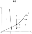
- Fig. 1 shows a pT phase diagram of water in which the three different states of matter solid S, liquid L and gaseous V are separated by drawn as a line phase boundaries.
- the static pressure p in the liquid is lowered, for example as a result of a rotation of a ship's propeller.
- the static pressure p decreases to the point where it reaches the boiling point curve SPK at the second state point P2
- steam cavitation starts even with a further drop in the pressure p, for example, up to the third state point P3, persists.
- Fig. 2 shows a plan view of a ship propeller 1, which comprises a propeller hub 2 and a plurality of propeller blades 3 attached thereto.
- the propeller 1 with the propeller blades 3 is brought in the operation of the propeller 1 in the water 5 by a shaft 4 for rotation.
- the shaft 4 protrudes through a sealed with a seal 10 against ingress of water 5 opening in a ship's skin 8 into the interior 9 of a ship's hull, where it can be rotated by a drive motor in rotation.
- the sound waves 7 emanating from the bubbles 6 reach a pressure sensor 11b arranged on a propeller blade 3.
- the sound waves 7 also strike the ship's skin 8 and stimulate them to vibrate.
- These vibrations can be detected by a vibration sensor 11c in contact with the ship's skin 8.
- the sound waves 7 hit the propeller 1 and cause it to vibrate.
- these vibrations are also detectable by a vibration sensor 11 c, which is in contact with the shaft 4.
- Fig. 3 shows a signal processing chain consisting of a sensor 11, a signal processing unit 12 and a control unit 13.
- the sensor 11 is one of the in Fig. 2 illustrated sensors 11a, 11b and 11c.
- the sensor 11 detects a noise caused by the air bubbles 6 associated with the gas and pseudocavitation, it sends a corresponding measurement signal 14 to the signal processing unit 12. It is possible for the sensor 11 to first send a measurement signal 14 to the signal processing unit 12 when the sound pressure level of the noise exceeds a predetermined threshold. However, it is also possible for the sensor 11 to generate measuring signals 14 independently of the sound pressure level of the noise, which it sends to the signal processing unit 12. In this case, an evaluation or filtering of the measurement signals 14 can be carried out by the signal processing unit 12.
- the signal transmission from the sensor 11 to the signal processing unit 12 is preferably conducted via a cable, for example via a conductor wire, since a wireless transmission by means of electromagnetic waves in the water may be subject to a relatively high absorption attenuation. If the Sensor is arranged on the rotating propeller, the electrical connection can be maintained by means arranged for example in the propeller hub sliding contacts.
- the signal processing unit 12 receives a measurement signal 14 that corresponds to a noise having a minimum sound pressure level, it generates data 15 relating to a change in the static pressure in the fluid.
- the data 15 may be in the form of a flag variable which simply indicates whether noise has been detected.
- the data 15 may include information about a sound level, a waveform, a frequency, and other characteristics of the noise.
- the data 15 may also include output data for output on an output device, e.g. include a screen or speaker to inform a user of the detected noise.
- the data 15 generated by the signal processing unit 12 includes input data for a control unit 13 which corresponds to the input data e.g. in a motor driving the shaft 4, a speed reduction or, in the case of a control device actuating the propeller blades 3, causes a change in the angle of attack of the propeller blades 3.
- Fig. 4 shows as a preferred embodiment of the present invention, a control circuit for operating a marine propeller.
- the sensor 11 may be one of the in Fig. 2 represented sensors 11a, 11b and 11c act.
- box 31 it is checked whether the sensor has detected a noise caused by gas cavitation and / or pseudo cavitation in the water.
- An assignment of a measured noise to a gas cavitation and / or pseudo cavitation may be e.g. based on characteristic properties of the measured value, such as frequencies, amplitudes, waveform, etc. In this way, a noise caused by gas cavitation and / or pseudo-cavitation can be distinguished from other noises.
- test in box 31 shows that the sensor has detected a noise in the water caused by gas cavitation and / or pseudo-cavitation Y
- a predetermined threshold e.g. based on a sound level or a vibration amplitude. If so, field 34 is reached in which a control signal 35 is generated, e.g. a command to be sent to a motor for reducing a rotational speed of the propeller or an instruction to be sent to an actuator for reducing an angle of attack of the propeller blades. Since the high volume of the noise indicates that there is a risk of entering the area of steam cavitation, these measures must increase the static pressure and thus reduce the thrust of the propeller. In parallel, the loop 36 returns to the field 30 so that a new measurement can take place.
- a control signal 35 e.g. a command to be sent to a motor for reducing a rotational speed of the propeller or an instruction to be sent to an actuator for reducing an angle of attack of the propeller blades. Since the high volume of the noise indicates
- a control signal 37 is generated in field 33, for example a command to increase the speed of the propeller or a command to be transmitted to the actuating device Command to increase the angle of attack of the propeller blades. Since the low volume of the noise indicates that there is still no danger of getting into the area of steam cavitation, these measures can further increase the thrust of the propeller and thus further increase the static pressure be lowered. In parallel, the loop 38 returns to the field 30 so that a new measurement can take place.
- test in box 31 shows that the sensor has detected no noise in the water caused by gas cavitation and / or pseudo-cavitation, then it is possible to proceed directly to box 33.
Landscapes
- Engineering & Computer Science (AREA)
- Chemical & Material Sciences (AREA)
- Combustion & Propulsion (AREA)
- Mechanical Engineering (AREA)
- Ocean & Marine Engineering (AREA)
- Remote Sensing (AREA)
- Radar, Positioning & Navigation (AREA)
- Aviation & Aerospace Engineering (AREA)
- Structures Of Non-Positive Displacement Pumps (AREA)
- Exhaust Silencers (AREA)
- Measuring Fluid Pressure (AREA)
- Investigating Or Analyzing Materials By The Use Of Ultrasonic Waves (AREA)
- Toys (AREA)
- Arrangements For Transmission Of Measured Signals (AREA)
Claims (5)
- Procédé pour faire fonctionner une hélice ( 1 ) de bateau, comprenant les stades suivants :- on détecte au moyen d'un capteur ( 11 ) un bruit provoqué par une cavitation de gaz et/ou une pseudo-cavitation sur un corps ( 1, 4, 8 ) solide, le bruit provoqué par la cavitation de gaz et/ou par la pseudo-cavitation étant mesuré acoustiquement sur le corps solide servant de conducteur acoustique ;- on transmet un signal ( 14 ) de mesure du capteur ( 11 ) par un procédé de transmission sans contact du capteur ( 11 ) à une unité ( 12 ) de traitement du signal ; et- on produit des instructions de commande par l'unité ( 12 ) de traitement du signal et en fonction du signal ( 14 ) de mesure reçu pour modifier la vitesse de rotation de l'hélice par un moteur d'entraînement et/ou pour modifier l'angle d'attaque de pale de l'hélice ( 1 ) du bateau par un moteur de réglage.
- Procédé suivant la revendication 1, dans lequel le corps ( 1, 4, 8 ) solide est l'hélice ( 1 ) du bateau et/ou un arbre ( 4 ) d'hélice servant à entraîner l'hélice ( 4 ) du bateau et/ou un bordé ( 8 ) du bateau.
- Procédé suivant la revendication 1 ou 2, dans lequel le procédé de transmission sans contact utilise des ondes électromagnétiques, de préférence dans le domaine radio ou dans le domaine optique.
- Dispositif pour faire fonctionner une hélice ( 1 ) de bateau, comprenant une unité ( 11 ) formant capteur, une unité de transmission du signal et une unité ( 12 ) de traitement du signal, le capteur ( 11 ) pouvant détecter sur un corps ( 1, 4, 8 ) solide un bruit provoqué par cavitation de gaz et/ou par pseudo-cavitation, caractérisé en ce que le bruit provoqué par cavitation de gaz et/ou par pseudo-cavitation est mesuré acoustiquement sur le corps solide servant de conducteur acoustique, l'unité de transmission du signal est propre à transmettre sans contact un signal ( 14 ) de mesure du capteur ( 11 ) à une unité ( 12 ) de traitement du signal et l'unité ( 12 ) de traitement du signal est propre en fonction du signal ( 14 ) de mesure reçu à produire des instructions de commande d'un moteur d'entraînement ou d'un moteur de réglage pour modifier la vitesse de rotation de l'hélice et/ou l'angle d'attaque de pale de l'hélice ( 1 ) du bateau.
- Dispositif suivant la revendication 4, caractérisé en ce que l'unité ( 11 ) formant capteur peut être montée sur un bâtiment de navigation, notamment sur l'hélice ( 1 ) d'un bateau et/ou sur un arbre ( 4 ) servant à l'entraînement de l'hélice ( 1 ) et/ou sur la coque d'un bâtiment de navigation.
Applications Claiming Priority (2)
| Application Number | Priority Date | Filing Date | Title |
|---|---|---|---|
| DE201210201539 DE102012201539A1 (de) | 2012-02-02 | 2012-02-02 | Gewinnen von Daten über einen Zustand einer Flüssigkeit |
| PCT/EP2013/051636 WO2013113681A1 (fr) | 2012-02-02 | 2013-01-29 | Procédé permettant de faire fonctionner une hélice marine |
Publications (2)
| Publication Number | Publication Date |
|---|---|
| EP2809574A1 EP2809574A1 (fr) | 2014-12-10 |
| EP2809574B1 true EP2809574B1 (fr) | 2016-03-23 |
Family
ID=47633048
Family Applications (1)
| Application Number | Title | Priority Date | Filing Date |
|---|---|---|---|
| EP13702427.9A Not-in-force EP2809574B1 (fr) | 2012-02-02 | 2013-01-29 | Procédé permettant de faire fonctionner une hélice marine |
Country Status (6)
| Country | Link |
|---|---|
| EP (1) | EP2809574B1 (fr) |
| KR (1) | KR101643833B1 (fr) |
| CN (1) | CN104093628B (fr) |
| AU (1) | AU2013214319B2 (fr) |
| DE (1) | DE102012201539A1 (fr) |
| WO (1) | WO2013113681A1 (fr) |
Cited By (1)
| Publication number | Priority date | Publication date | Assignee | Title |
|---|---|---|---|---|
| WO2023041421A1 (fr) * | 2021-09-16 | 2023-03-23 | Thyssenkrupp Marine Systems Gmbh | Prévention de cavitation, indépendamment de la position, au niveau d'une hélice |
Families Citing this family (15)
| Publication number | Priority date | Publication date | Assignee | Title |
|---|---|---|---|---|
| EP2634084A1 (fr) * | 2012-02-29 | 2013-09-04 | ABB Oy | Agencement et procédé pour navire |
| CN104374544A (zh) * | 2014-12-10 | 2015-02-25 | 中国人民解放军海军工程大学 | 螺旋桨脉动压力非对称测量装置 |
| EP3263441A1 (fr) | 2016-06-28 | 2018-01-03 | ABB Schweiz AG | Commande de mouvement d'arbre d'hélice |
| KR101879515B1 (ko) * | 2016-12-19 | 2018-07-18 | 한국해양과학기술원 | 쌍축선의 실시간 진동 정보와 프로펠러 회전각 조절을 통한 변동압력 저감 방법 |
| KR101884534B1 (ko) * | 2016-12-19 | 2018-08-01 | 한국해양과학기술원 | 쌍축선의 프로펠러 회전각 조절을 통한 선체 변동압력 저감 방법 |
| JP6758210B2 (ja) * | 2017-01-31 | 2020-09-23 | 三菱重工業株式会社 | ダクト装置および船舶 |
| JP7198770B2 (ja) * | 2017-04-21 | 2023-01-04 | ニューサウス イノベーションズ ピーティーワイ リミテッド | キャビテーションの防止 |
| GB201707565D0 (en) * | 2017-05-11 | 2017-06-28 | Oscar Propulsion Ltd | Cavitation and noise reduction |
| KR102561811B1 (ko) * | 2018-10-08 | 2023-07-31 | 한화오션 주식회사 | 트윈스케그 선박의 프로펠러 제어 장치 |
| CN112129536B (zh) * | 2020-08-24 | 2023-04-07 | 孙勇 | 帆船赛事机械动力检测仪 |
| KR102449485B1 (ko) * | 2022-06-24 | 2022-09-29 | 김동현 | 복수의 블레이드가 세그먼트 타입으로 장착되어 내구성이 향상되고 교체비용을 절약할 수 있으며 운행 중 블레이드의 파손을 감지할 수 있는 선박용 프로펠러 |
| KR102449486B1 (ko) * | 2022-06-24 | 2022-09-29 | 김동현 | 갈바닉 효과에 의한 허브의 부식이 방지되고 운행 중 블레이드의 파손을 감지할 수 있는 선박용 프로펠러 |
| CN116353779B (zh) * | 2023-04-23 | 2025-11-18 | 江苏科技大学 | 一种适用于极地破冰船的辅助破冰系统 |
| KR102610005B1 (ko) * | 2023-09-01 | 2023-12-05 | 주식회사 모쓰 | 캐비테이션 저감을 위한 선박용 프로펠러 회전속도 제어 방법 |
| KR102629766B1 (ko) * | 2023-09-01 | 2024-01-29 | 주식회사 모쓰 | 캐비테이션 저감을 위한 선박용 프로펠러 회전속도 제어 장치 |
Family Cites Families (14)
| Publication number | Priority date | Publication date | Assignee | Title |
|---|---|---|---|---|
| DE48278C (de) * | 1970-07-17 | E. CA-REZ in Brüssel, Nr. 72 Rue du Marais | Neuerung bei dem Verfahren zur Darstellung von Ammoniumnitrat durch Umsetzen von Bariumnitrat mit Ammoniumsulfat | |
| DE3236815C2 (de) * | 1982-10-05 | 1985-09-19 | Klaus Dipl.-Ing.(FH) 3200 Hildesheim Metzger | Überwachungs- und Kontrolleinrichtung an Rohrleitungen zum Transport von Flüssigkeiten |
| JPH0659864B2 (ja) * | 1985-04-08 | 1994-08-10 | 三井造船株式会社 | 水中音の計測装置 |
| JP2592999B2 (ja) * | 1991-01-10 | 1997-03-19 | 沖電気工業株式会社 | キャビテーション雑音検出方法 |
| DE19517289A1 (de) * | 1995-05-11 | 1996-11-14 | Klein Schanzlin & Becker Ag | Überwachungssystem zur Feststellung einer Kavitationsintensität |
| EP1286882A1 (fr) * | 2000-05-05 | 2003-03-05 | Saunders, Amanda Maria | Tunnel anti-cavitation tunnel pour h lices de navires |
| US20040090195A1 (en) | 2001-06-11 | 2004-05-13 | Motsenbocker Marvin A. | Efficient control, monitoring and energy devices for vehicles such as watercraft |
| US7443079B2 (en) * | 2004-09-17 | 2008-10-28 | Product Systems Incorporated | Method and apparatus for cavitation threshold characterization and control |
| KR20050073437A (ko) * | 2005-06-22 | 2005-07-13 | 정찬희 | 프로펠러에 있어서 캐비테이션 저감방법 및 수단 |
| US20100056924A1 (en) * | 2006-11-20 | 2010-03-04 | Koninklijke Philips Electronics N.V. | Control and display of ultrasonic microbubble cavitation |
| GB2451438B (en) * | 2007-07-27 | 2011-06-08 | Secretary Trade Ind Brit | Cavitation detection |
| DE202008006069U1 (de) * | 2008-03-10 | 2008-07-17 | Becker Marine Systems Gmbh & Co. Kg | Vorrichtung zur Verringerung des Antriebsleistungsbedarfes eines Schiffes |
| KR101180579B1 (ko) * | 2009-08-24 | 2012-09-06 | 주식회사 디.에스.케이 | 가변피치 프로펠러의 공기방출관의 자동제어 시스템 |
| US8441956B2 (en) * | 2010-01-29 | 2013-05-14 | Honda Motor Co., Ltd. | Marine wireless communication system |
-
2012
- 2012-02-02 DE DE201210201539 patent/DE102012201539A1/de not_active Ceased
-
2013
- 2013-01-29 AU AU2013214319A patent/AU2013214319B2/en not_active Ceased
- 2013-01-29 CN CN201380008038.7A patent/CN104093628B/zh not_active Expired - Fee Related
- 2013-01-29 EP EP13702427.9A patent/EP2809574B1/fr not_active Not-in-force
- 2013-01-29 WO PCT/EP2013/051636 patent/WO2013113681A1/fr not_active Ceased
- 2013-01-29 KR KR1020147021405A patent/KR101643833B1/ko not_active Expired - Fee Related
Cited By (1)
| Publication number | Priority date | Publication date | Assignee | Title |
|---|---|---|---|---|
| WO2023041421A1 (fr) * | 2021-09-16 | 2023-03-23 | Thyssenkrupp Marine Systems Gmbh | Prévention de cavitation, indépendamment de la position, au niveau d'une hélice |
Also Published As
| Publication number | Publication date |
|---|---|
| AU2013214319A1 (en) | 2014-08-07 |
| WO2013113681A1 (fr) | 2013-08-08 |
| AU2013214319B2 (en) | 2015-07-23 |
| CN104093628B (zh) | 2017-06-13 |
| KR20140107664A (ko) | 2014-09-04 |
| CN104093628A (zh) | 2014-10-08 |
| KR101643833B1 (ko) | 2016-07-28 |
| EP2809574A1 (fr) | 2014-12-10 |
| DE102012201539A1 (de) | 2013-08-08 |
Similar Documents
| Publication | Publication Date | Title |
|---|---|---|
| EP2809574B1 (fr) | Procédé permettant de faire fonctionner une hélice marine | |
| EP3801276B1 (fr) | Procédé pour la détermination d'une vitesse d'écoulement d'un fluide s'écoulant dans un système de support vasculaire implanté et système de support vasculaire implantable | |
| EP2616785B1 (fr) | Navire équipé d'un rotor à effet magnus et dispositif de mesure de force | |
| DE102013227196A1 (de) | Sensor mit drei Modi zum Bestimmen einer Temperatur, eines Pegels und einer Konzentration eines Fluids | |
| DE2502020A1 (de) | Verfahren zum positionieren eines wasserfahrzeugs | |
| EP0417225A1 (fr) | Procede et dispositif de reduction du bruit emis par les sous-marins immerges. | |
| EP0742372B1 (fr) | Système de surveillance pour détecter l'intensité de la cavitation | |
| EP2876041A1 (fr) | Agencement de détermination d'une force agissant sur un gouvernail | |
| DE102021207842A1 (de) | Ausstiegswarnvorrichtung und -verfahren für einen insassen | |
| DE69830293T2 (de) | Verfahren zur Anzeige von Planarströmung | |
| DE112015004928T5 (de) | Schwimmende Unterwasser-Meeresströmungsstromerzeugungsvorrichtung | |
| EP3889553B1 (fr) | Procédé et dispositif de détection d'une cavitation lors d'un passage d'un liquide à travers un élément de régulation | |
| Tani et al. | Cavitation tunnel tests for “The Princess Royal” model propeller behind a 2-dimensional wake screen | |
| WO2023041421A1 (fr) | Prévention de cavitation, indépendamment de la position, au niveau d'une hélice | |
| DE2134825C2 (de) | Kavitationsmeßvorrichtung | |
| DE102018101126A1 (de) | System und Verfahren zum Reduzieren von pulsierendem Windgeräusch | |
| DE10223196A1 (de) | Verfahren und Einrichtung zum Transferieren medizinisch wirksamer Stoffe in Zellen | |
| WO2014016110A1 (fr) | Procédé pour déterminer une distribution de tailles de bulles et dispositif de mesure | |
| DE112014000290T5 (de) | Akustik-Messvorrichtung | |
| DE102014113600A1 (de) | Verfahren und Vorrichtung zum Öffnen eines Flügelelements eines Kraftfahrzeugs, sowie Kraftfahrzeug | |
| DE102012106233A1 (de) | Pendelanzeiger | |
| EP2202145B1 (fr) | Diagnose d'entraînements navals | |
| DE102014118035A1 (de) | Verfahren zum Erkennen einer Abschattung einer Sensoreinrichtung eines Kraftfahrzeugs durch ein Objekt, Recheneinrichtung, Fahrerassistenzsystem sowie Kraftfahrzeug | |
| DE102019127859A1 (de) | Positionsbestimmung eines Objekts mittels Ultraschall | |
| WO2021018451A1 (fr) | Procédé et appareil de détection d'au moins une immersion partielle d'un véhicule automobile |
Legal Events
| Date | Code | Title | Description |
|---|---|---|---|
| PUAI | Public reference made under article 153(3) epc to a published international application that has entered the european phase |
Free format text: ORIGINAL CODE: 0009012 |
|
| 17P | Request for examination filed |
Effective date: 20140728 |
|
| AK | Designated contracting states |
Kind code of ref document: A1 Designated state(s): AL AT BE BG CH CY CZ DE DK EE ES FI FR GB GR HR HU IE IS IT LI LT LU LV MC MK MT NL NO PL PT RO RS SE SI SK SM TR |
|
| AX | Request for extension of the european patent |
Extension state: BA ME |
|
| DAX | Request for extension of the european patent (deleted) | ||
| GRAP | Despatch of communication of intention to grant a patent |
Free format text: ORIGINAL CODE: EPIDOSNIGR1 |
|
| INTG | Intention to grant announced |
Effective date: 20150907 |
|
| GRAS | Grant fee paid |
Free format text: ORIGINAL CODE: EPIDOSNIGR3 |
|
| GRAA | (expected) grant |
Free format text: ORIGINAL CODE: 0009210 |
|
| AK | Designated contracting states |
Kind code of ref document: B1 Designated state(s): AL AT BE BG CH CY CZ DE DK EE ES FI FR GB GR HR HU IE IS IT LI LT LU LV MC MK MT NL NO PL PT RO RS SE SI SK SM TR |
|
| REG | Reference to a national code |
Ref country code: GB Ref legal event code: FG4D Free format text: NOT ENGLISH |
|
| REG | Reference to a national code |
Ref country code: CH Ref legal event code: EP |
|
| REG | Reference to a national code |
Ref country code: AT Ref legal event code: REF Ref document number: 782869 Country of ref document: AT Kind code of ref document: T Effective date: 20160415 |
|
| REG | Reference to a national code |
Ref country code: IE Ref legal event code: FG4D Free format text: LANGUAGE OF EP DOCUMENT: GERMAN |
|
| REG | Reference to a national code |
Ref country code: DE Ref legal event code: R096 Ref document number: 502013002283 Country of ref document: DE |
|
| REG | Reference to a national code |
Ref country code: NL Ref legal event code: FP |
|
| REG | Reference to a national code |
Ref country code: NO Ref legal event code: T2 Effective date: 20160323 Ref country code: LT Ref legal event code: MG4D |
|
| PG25 | Lapsed in a contracting state [announced via postgrant information from national office to epo] |
Ref country code: GR Free format text: LAPSE BECAUSE OF FAILURE TO SUBMIT A TRANSLATION OF THE DESCRIPTION OR TO PAY THE FEE WITHIN THE PRESCRIBED TIME-LIMIT Effective date: 20160624 Ref country code: HR Free format text: LAPSE BECAUSE OF FAILURE TO SUBMIT A TRANSLATION OF THE DESCRIPTION OR TO PAY THE FEE WITHIN THE PRESCRIBED TIME-LIMIT Effective date: 20160323 |
|
| PG25 | Lapsed in a contracting state [announced via postgrant information from national office to epo] |
Ref country code: RS Free format text: LAPSE BECAUSE OF FAILURE TO SUBMIT A TRANSLATION OF THE DESCRIPTION OR TO PAY THE FEE WITHIN THE PRESCRIBED TIME-LIMIT Effective date: 20160323 Ref country code: SE Free format text: LAPSE BECAUSE OF FAILURE TO SUBMIT A TRANSLATION OF THE DESCRIPTION OR TO PAY THE FEE WITHIN THE PRESCRIBED TIME-LIMIT Effective date: 20160323 Ref country code: LT Free format text: LAPSE BECAUSE OF FAILURE TO SUBMIT A TRANSLATION OF THE DESCRIPTION OR TO PAY THE FEE WITHIN THE PRESCRIBED TIME-LIMIT Effective date: 20160323 Ref country code: LV Free format text: LAPSE BECAUSE OF FAILURE TO SUBMIT A TRANSLATION OF THE DESCRIPTION OR TO PAY THE FEE WITHIN THE PRESCRIBED TIME-LIMIT Effective date: 20160323 |
|
| PG25 | Lapsed in a contracting state [announced via postgrant information from national office to epo] |
Ref country code: PL Free format text: LAPSE BECAUSE OF FAILURE TO SUBMIT A TRANSLATION OF THE DESCRIPTION OR TO PAY THE FEE WITHIN THE PRESCRIBED TIME-LIMIT Effective date: 20160323 Ref country code: IS Free format text: LAPSE BECAUSE OF FAILURE TO SUBMIT A TRANSLATION OF THE DESCRIPTION OR TO PAY THE FEE WITHIN THE PRESCRIBED TIME-LIMIT Effective date: 20160723 Ref country code: EE Free format text: LAPSE BECAUSE OF FAILURE TO SUBMIT A TRANSLATION OF THE DESCRIPTION OR TO PAY THE FEE WITHIN THE PRESCRIBED TIME-LIMIT Effective date: 20160323 |
|
| PG25 | Lapsed in a contracting state [announced via postgrant information from national office to epo] |
Ref country code: SM Free format text: LAPSE BECAUSE OF FAILURE TO SUBMIT A TRANSLATION OF THE DESCRIPTION OR TO PAY THE FEE WITHIN THE PRESCRIBED TIME-LIMIT Effective date: 20160323 Ref country code: PT Free format text: LAPSE BECAUSE OF FAILURE TO SUBMIT A TRANSLATION OF THE DESCRIPTION OR TO PAY THE FEE WITHIN THE PRESCRIBED TIME-LIMIT Effective date: 20160725 Ref country code: SK Free format text: LAPSE BECAUSE OF FAILURE TO SUBMIT A TRANSLATION OF THE DESCRIPTION OR TO PAY THE FEE WITHIN THE PRESCRIBED TIME-LIMIT Effective date: 20160323 Ref country code: CZ Free format text: LAPSE BECAUSE OF FAILURE TO SUBMIT A TRANSLATION OF THE DESCRIPTION OR TO PAY THE FEE WITHIN THE PRESCRIBED TIME-LIMIT Effective date: 20160323 Ref country code: ES Free format text: LAPSE BECAUSE OF FAILURE TO SUBMIT A TRANSLATION OF THE DESCRIPTION OR TO PAY THE FEE WITHIN THE PRESCRIBED TIME-LIMIT Effective date: 20160323 Ref country code: RO Free format text: LAPSE BECAUSE OF FAILURE TO SUBMIT A TRANSLATION OF THE DESCRIPTION OR TO PAY THE FEE WITHIN THE PRESCRIBED TIME-LIMIT Effective date: 20160323 |
|
| PG25 | Lapsed in a contracting state [announced via postgrant information from national office to epo] |
Ref country code: IT Free format text: LAPSE BECAUSE OF FAILURE TO SUBMIT A TRANSLATION OF THE DESCRIPTION OR TO PAY THE FEE WITHIN THE PRESCRIBED TIME-LIMIT Effective date: 20160323 |
|
| REG | Reference to a national code |
Ref country code: DE Ref legal event code: R097 Ref document number: 502013002283 Country of ref document: DE |
|
| PLBE | No opposition filed within time limit |
Free format text: ORIGINAL CODE: 0009261 |
|
| STAA | Information on the status of an ep patent application or granted ep patent |
Free format text: STATUS: NO OPPOSITION FILED WITHIN TIME LIMIT |
|
| PG25 | Lapsed in a contracting state [announced via postgrant information from national office to epo] |
Ref country code: DK Free format text: LAPSE BECAUSE OF FAILURE TO SUBMIT A TRANSLATION OF THE DESCRIPTION OR TO PAY THE FEE WITHIN THE PRESCRIBED TIME-LIMIT Effective date: 20160323 |
|
| PG25 | Lapsed in a contracting state [announced via postgrant information from national office to epo] |
Ref country code: BG Free format text: LAPSE BECAUSE OF FAILURE TO SUBMIT A TRANSLATION OF THE DESCRIPTION OR TO PAY THE FEE WITHIN THE PRESCRIBED TIME-LIMIT Effective date: 20160623 |
|
| 26N | No opposition filed |
Effective date: 20170102 |
|
| PG25 | Lapsed in a contracting state [announced via postgrant information from national office to epo] |
Ref country code: SI Free format text: LAPSE BECAUSE OF FAILURE TO SUBMIT A TRANSLATION OF THE DESCRIPTION OR TO PAY THE FEE WITHIN THE PRESCRIBED TIME-LIMIT Effective date: 20160323 Ref country code: BE Free format text: LAPSE BECAUSE OF NON-PAYMENT OF DUE FEES Effective date: 20170131 |
|
| REG | Reference to a national code |
Ref country code: CH Ref legal event code: PL |
|
| PG25 | Lapsed in a contracting state [announced via postgrant information from national office to epo] |
Ref country code: MC Free format text: LAPSE BECAUSE OF FAILURE TO SUBMIT A TRANSLATION OF THE DESCRIPTION OR TO PAY THE FEE WITHIN THE PRESCRIBED TIME-LIMIT Effective date: 20160323 |
|
| REG | Reference to a national code |
Ref country code: FR Ref legal event code: ST Effective date: 20170929 |
|
| PG25 | Lapsed in a contracting state [announced via postgrant information from national office to epo] |
Ref country code: FR Free format text: LAPSE BECAUSE OF NON-PAYMENT OF DUE FEES Effective date: 20170131 Ref country code: CH Free format text: LAPSE BECAUSE OF NON-PAYMENT OF DUE FEES Effective date: 20170131 Ref country code: LI Free format text: LAPSE BECAUSE OF NON-PAYMENT OF DUE FEES Effective date: 20170131 |
|
| REG | Reference to a national code |
Ref country code: IE Ref legal event code: MM4A |
|
| PG25 | Lapsed in a contracting state [announced via postgrant information from national office to epo] |
Ref country code: LU Free format text: LAPSE BECAUSE OF NON-PAYMENT OF DUE FEES Effective date: 20170129 |
|
| REG | Reference to a national code |
Ref country code: BE Ref legal event code: MM Effective date: 20170131 |
|
| PG25 | Lapsed in a contracting state [announced via postgrant information from national office to epo] |
Ref country code: IE Free format text: LAPSE BECAUSE OF NON-PAYMENT OF DUE FEES Effective date: 20170129 |
|
| PG25 | Lapsed in a contracting state [announced via postgrant information from national office to epo] |
Ref country code: MT Free format text: LAPSE BECAUSE OF FAILURE TO SUBMIT A TRANSLATION OF THE DESCRIPTION OR TO PAY THE FEE WITHIN THE PRESCRIBED TIME-LIMIT Effective date: 20160323 |
|
| PG25 | Lapsed in a contracting state [announced via postgrant information from national office to epo] |
Ref country code: AL Free format text: LAPSE BECAUSE OF FAILURE TO SUBMIT A TRANSLATION OF THE DESCRIPTION OR TO PAY THE FEE WITHIN THE PRESCRIBED TIME-LIMIT Effective date: 20160323 |
|
| REG | Reference to a national code |
Ref country code: AT Ref legal event code: MM01 Ref document number: 782869 Country of ref document: AT Kind code of ref document: T Effective date: 20180129 |
|
| PG25 | Lapsed in a contracting state [announced via postgrant information from national office to epo] |
Ref country code: AT Free format text: LAPSE BECAUSE OF NON-PAYMENT OF DUE FEES Effective date: 20180129 |
|
| PG25 | Lapsed in a contracting state [announced via postgrant information from national office to epo] |
Ref country code: HU Free format text: LAPSE BECAUSE OF FAILURE TO SUBMIT A TRANSLATION OF THE DESCRIPTION OR TO PAY THE FEE WITHIN THE PRESCRIBED TIME-LIMIT; INVALID AB INITIO Effective date: 20130129 |
|
| PG25 | Lapsed in a contracting state [announced via postgrant information from national office to epo] |
Ref country code: CY Free format text: LAPSE BECAUSE OF FAILURE TO SUBMIT A TRANSLATION OF THE DESCRIPTION OR TO PAY THE FEE WITHIN THE PRESCRIBED TIME-LIMIT Effective date: 20160323 |
|
| PG25 | Lapsed in a contracting state [announced via postgrant information from national office to epo] |
Ref country code: MK Free format text: LAPSE BECAUSE OF FAILURE TO SUBMIT A TRANSLATION OF THE DESCRIPTION OR TO PAY THE FEE WITHIN THE PRESCRIBED TIME-LIMIT Effective date: 20160323 |
|
| PG25 | Lapsed in a contracting state [announced via postgrant information from national office to epo] |
Ref country code: TR Free format text: LAPSE BECAUSE OF FAILURE TO SUBMIT A TRANSLATION OF THE DESCRIPTION OR TO PAY THE FEE WITHIN THE PRESCRIBED TIME-LIMIT Effective date: 20160323 |
|
| REG | Reference to a national code |
Ref country code: DE Ref legal event code: R081 Ref document number: 502013002283 Country of ref document: DE Owner name: SIEMENS ENERGY GLOBAL GMBH & CO. KG, DE Free format text: FORMER OWNER: SIEMENS AKTIENGESELLSCHAFT, 80333 MUENCHEN, DE |
|
| PGFP | Annual fee paid to national office [announced via postgrant information from national office to epo] |
Ref country code: FI Payment date: 20210121 Year of fee payment: 9 Ref country code: NO Payment date: 20210111 Year of fee payment: 9 Ref country code: NL Payment date: 20210104 Year of fee payment: 9 |
|
| PGFP | Annual fee paid to national office [announced via postgrant information from national office to epo] |
Ref country code: GB Payment date: 20210202 Year of fee payment: 9 Ref country code: DE Payment date: 20210319 Year of fee payment: 9 |
|
| REG | Reference to a national code |
Ref country code: DE Ref legal event code: R119 Ref document number: 502013002283 Country of ref document: DE |
|
| REG | Reference to a national code |
Ref country code: FI Ref legal event code: MAE |
|
| REG | Reference to a national code |
Ref country code: NO Ref legal event code: MMEP |
|
| REG | Reference to a national code |
Ref country code: NL Ref legal event code: MM Effective date: 20220201 |
|
| GBPC | Gb: european patent ceased through non-payment of renewal fee |
Effective date: 20220129 |
|
| PG25 | Lapsed in a contracting state [announced via postgrant information from national office to epo] |
Ref country code: NO Free format text: LAPSE BECAUSE OF NON-PAYMENT OF DUE FEES Effective date: 20220131 Ref country code: NL Free format text: LAPSE BECAUSE OF NON-PAYMENT OF DUE FEES Effective date: 20220201 Ref country code: GB Free format text: LAPSE BECAUSE OF NON-PAYMENT OF DUE FEES Effective date: 20220129 Ref country code: FI Free format text: LAPSE BECAUSE OF NON-PAYMENT OF DUE FEES Effective date: 20220129 Ref country code: DE Free format text: LAPSE BECAUSE OF NON-PAYMENT OF DUE FEES Effective date: 20220802 |