EP2634084A1 - Agencement et procédé pour navire - Google Patents
Agencement et procédé pour navire Download PDFInfo
- Publication number
- EP2634084A1 EP2634084A1 EP12157439.6A EP12157439A EP2634084A1 EP 2634084 A1 EP2634084 A1 EP 2634084A1 EP 12157439 A EP12157439 A EP 12157439A EP 2634084 A1 EP2634084 A1 EP 2634084A1
- Authority
- EP
- European Patent Office
- Prior art keywords
- propeller
- ship
- situated
- oscillation sensor
- support structure
- Prior art date
- Legal status (The legal status is an assumption and is not a legal conclusion. Google has not performed a legal analysis and makes no representation as to the accuracy of the status listed.)
- Withdrawn
Links
- 238000000034 method Methods 0.000 title claims description 7
- 230000010355 oscillation Effects 0.000 claims abstract description 50
- 230000005540 biological transmission Effects 0.000 claims abstract description 13
- 241001544487 Macromiidae Species 0.000 claims description 3
- 239000003949 liquefied natural gas Substances 0.000 claims description 3
- 230000001276 controlling effect Effects 0.000 claims 1
- 230000001105 regulatory effect Effects 0.000 claims 1
- XLYOFNOQVPJJNP-UHFFFAOYSA-N water Substances O XLYOFNOQVPJJNP-UHFFFAOYSA-N 0.000 description 13
- 239000000969 carrier Substances 0.000 description 2
- 230000006698 induction Effects 0.000 description 2
- 238000002347 injection Methods 0.000 description 2
- 239000007924 injection Substances 0.000 description 2
- 238000005259 measurement Methods 0.000 description 2
- 230000001902 propagating effect Effects 0.000 description 2
- 239000003381 stabilizer Substances 0.000 description 2
- 230000001360 synchronised effect Effects 0.000 description 2
- 230000001133 acceleration Effects 0.000 description 1
- 230000007423 decrease Effects 0.000 description 1
- 238000013461 design Methods 0.000 description 1
- 238000001514 detection method Methods 0.000 description 1
- 230000003993 interaction Effects 0.000 description 1
- 239000007788 liquid Substances 0.000 description 1
- 238000012986 modification Methods 0.000 description 1
- 230000004048 modification Effects 0.000 description 1
- 230000002265 prevention Effects 0.000 description 1
- 238000012545 processing Methods 0.000 description 1
- 230000005855 radiation Effects 0.000 description 1
- 230000035945 sensitivity Effects 0.000 description 1
Images


Classifications
-
- B—PERFORMING OPERATIONS; TRANSPORTING
- B63—SHIPS OR OTHER WATERBORNE VESSELS; RELATED EQUIPMENT
- B63B—SHIPS OR OTHER WATERBORNE VESSELS; EQUIPMENT FOR SHIPPING
- B63B17/00—Vessels parts, details, or accessories, not otherwise provided for
-
- B—PERFORMING OPERATIONS; TRANSPORTING
- B63—SHIPS OR OTHER WATERBORNE VESSELS; RELATED EQUIPMENT
- B63H—MARINE PROPULSION OR STEERING
- B63H1/00—Propulsive elements directly acting on water
- B63H1/02—Propulsive elements directly acting on water of rotary type
- B63H1/12—Propulsive elements directly acting on water of rotary type with rotation axis substantially in propulsive direction
- B63H1/14—Propellers
- B63H1/18—Propellers with means for diminishing cavitation, e.g. supercavitation
-
- B—PERFORMING OPERATIONS; TRANSPORTING
- B63—SHIPS OR OTHER WATERBORNE VESSELS; RELATED EQUIPMENT
- B63H—MARINE PROPULSION OR STEERING
- B63H21/00—Use of propulsion power plant or units on vessels
- B63H21/21—Control means for engine or transmission, specially adapted for use on marine vessels
-
- B—PERFORMING OPERATIONS; TRANSPORTING
- B63—SHIPS OR OTHER WATERBORNE VESSELS; RELATED EQUIPMENT
- B63H—MARINE PROPULSION OR STEERING
- B63H23/00—Transmitting power from propulsion power plant to propulsive elements
-
- B—PERFORMING OPERATIONS; TRANSPORTING
- B63—SHIPS OR OTHER WATERBORNE VESSELS; RELATED EQUIPMENT
- B63H—MARINE PROPULSION OR STEERING
- B63H25/00—Steering; Slowing-down otherwise than by use of propulsive elements; Dynamic anchoring, i.e. positioning vessels by means of main or auxiliary propulsive elements
-
- B—PERFORMING OPERATIONS; TRANSPORTING
- B63—SHIPS OR OTHER WATERBORNE VESSELS; RELATED EQUIPMENT
- B63H—MARINE PROPULSION OR STEERING
- B63H25/00—Steering; Slowing-down otherwise than by use of propulsive elements; Dynamic anchoring, i.e. positioning vessels by means of main or auxiliary propulsive elements
- B63H25/06—Steering by rudders
-
- B—PERFORMING OPERATIONS; TRANSPORTING
- B63—SHIPS OR OTHER WATERBORNE VESSELS; RELATED EQUIPMENT
- B63H—MARINE PROPULSION OR STEERING
- B63H21/00—Use of propulsion power plant or units on vessels
- B63H21/21—Control means for engine or transmission, specially adapted for use on marine vessels
- B63H2021/216—Control means for engine or transmission, specially adapted for use on marine vessels using electric control means
Definitions
- the invention relates to an arrangement in a ship according to the preamble of claim 1.
- the invention also relates to a method in a ship according to the preamble of claim 12.
- the arrangement and the method can be used in a ship comprising a hull, at least one propulsion engine, transmission means, at least one propeller connected via the transmission means to the at least one propulsion engine and a support structure comprising an upper portion being supported at the hull, a lower portion, and a front edge, a control unit for controlling the at least one propulsion engine.
- the ship can have only one propulsion engine or two or more propulsion engines situated at the stern of the ship.
- the propeller can comprise a single propeller or two contra-rotating propellers.
- the arrangement is suitable to be used especially in large ships e.g. cruisers, tankers transporting oil or liquefied natural gas, vehicle carriers, container ships and ferries.
- JP patent publication No. 2004182096 discloses a pod-type propulsion apparatus comprising a support structure being pivotably attached to the hull of a ship and a chamber attached to the support structure.
- the chamber comprises a motor being connected to a first end of a shaft, the second opposite end of the shaft protruding from the front end of the chamber and being connected to a propeller.
- the rotation angle of the support structure is limited when the speed of the ship increases in order to prevent cavitation.
- RU patent publication No. 2009957 discloses a device to reduce cavitation in a ship.
- the propeller at the stern of the ship is connected via a shaft to a motor within the hull of the ship.
- a cavitational noise sensor is located on the hull of the ship.
- An oscillation frequency control block for the flexible casings is connected in series with the noise sensor.
- the propeller shaft is fitted with a collector with brushes.
- the sensor generates a signal which is proportional to the acoustic radiations and feeds it as an input signal to the oscillation frequency control block.
- the oscillation frequency control block in turn generates a return signal to the drives for the flexible oscillation casings in order to reduce cavitational noise to the minimum.
- JP patent publication No. 09136694 discloses automatic speed control of a water jet pump used in a ship.
- a pressure sensor detects the delivery pressure of the water jet pump when the ship is moving.
- a calculator calculates the number of revolutions that can be applied to the water jet pump in order to avoid cavitation generation in water current based on the output signal of the pressure detector.
- a signal selector compares the calculated number of revolutions and the number of revolutions indicated by a steering control unit. The signal selector outputs a control signal to a drive motor of the water jet pump by selecting the signal that indicates the smaller number of revolutions.
- JP patent publication 09109991 discloses a cavitation prevention type ship fin stabilizer.
- the stabilizer includes a fin being pivotably supported to the hull through a shaft.
- a fin driving mechanism adjusts wing angle of the fin by turning the shaft.
- a water exhaust nozzle at the lower rear edge of the fin controls cavitation generation of the fin while cruising.
- a feed water pump supplies water and discharges water from the exhaust nozzle.
- a water injection controller controls the water injection from the exhaust nozzle by controlling the feed pump based on the noise detection signal of the microphone.
- Cavitation occurs when liquid changes its phase into vapour at a certain flow region where local pressure is very low due to high local velocities.
- At least four different cavitation types relating to a rotating propeller in water can be distinguished: a) tip vortex from the suction side, which is regarded as normal operation until a certain level is exceeded, b) sheet cavitation at suction side, c) tip vortex from the pressure side, d) bubble cavitation.
- the control bridge is at the stern of the ship i.e. 200 to 400 meters ahead of the aft in a big ship.
- the control bridge is also 15-40 meters above sea level. This means that the captain or navigating officer sitting on the navigation bridge do not normally feel or hear cavitation caused by the propellers at the aft of the ship. There is thus a need to make the captain and/or the navigating officer aware of situations where worse degree cavitation is emerging. Such situations might typically occur when the ship is suddenly accelerated with full power or when the propulsion unit and/or the ship is turned at big turning angels.
- the obj ect of the invention is an arrangement and method to manage situations where cavitation occurs in a ship.
- the method in a ship according to the invention is characterized by the features in the characterizing portion of claim 12.
- the arrangement in a ship according to the invention comprises a hull, at least one propulsion unit comprising a propulsion engine, transmission means, at least one propeller connected via the transmission means to the propulsion engine, and an oscillation sensor situated in the vicinity of the at least one propeller in order to sense oscillations caused by cavitation of the at least one propeller.
- the arrangement comprises further a control unit for controlling the at least one propulsion engine, said oscillation sensor being connected to the control unit, whereby the output signal of the oscillation sensor is analyzed in the control unit in order to determine whether a worse degree cavitation is emerging, and indicate that a worse degree cavitation is emerging on a display unit at the navigation bridge and/or regulate the rotation speed and/or the power of the at least one propulsion engine when worse degree cavitation is emerging.
- control unit sends a warning to a display unit at the navigation bridge and/or controls the speed and/or the power of the propulsion engine.
- the amount of tuning parameters in the system is limited to a minimum.
- the only tuning parameters are sensitivity in the propeller blade frequency, the type of burst and the amplitude.
- the signal processing of the raw measurements is also rather simple, which means that the indication of worse case cavitation will be fast.
- the speed ramps of the propulsion unit are normally relative low, which means that there is plenty of time to react before more severe cavitation emerges.
- First stage tip vortex cavitation is normal in operation e.g. in the case the ship drives at full speed.
- First stage tip vortex is also normally taken into account in hydrodynamic design and the operation efficiency of the propeller is not harmfully affected by first stage tip vortex.
- the cavitation gets worse, it will be harmful for the whole propulsion mechanics and may cause instant or long run damage.
- a worse class cavitation will result in a collapse of the efficiency of the propeller, which decreases the maneuverability of the ship dramatically.
- the best position of the oscillation sensor for sensing the tip vortex of the propeller is on a support structure situated behind the propeller in the driving direction of the ship at a place where the tip vortex 'rope' hits the support structure.
- the support structure is behind the propeller in a normal pulling type propulsion unit i.e. in a propulsion unit where the propeller is at the front end of the chamber.
- the support structure creates a different density in the hydrodynamic environment as the propeller blade passes in front of the support structure.
- the tip vortex and the support structure affect together.
- the interaction between the tip vortex and the support structure will create propeller blade frequency bursts when the tip vortex gets worse. This point is the borderline to start actions in propulsion control for avoiding more severe cavitation.
- the invention can advantageously be used in large ships e.g. cruisers, tankers transporting oil or liquefied natural gas, vehicle carriers, container ships and ferries.
- the power of the propulsion unit in such large ships is in the order of at least 1 MW.
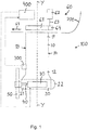
- Figure 1 shows an arrangement according to the invention in a ship with a pod propulsion unit.
- the arrangement comprises a propulsion unit 100 situated at the stern of the ship.
- the propulsion unit 100 comprises a support structure 10, a chamber 20, a propulsion engine comprising a first electric motor 30, a shaft 40, and a propeller 50.
- the support structure 10 has an upper portion 11, a lower portion 12, a front edge 13 and a rear edge 14.
- the upper portion 11 of the hollow support structure 10 is pivotably attached to the hull 200 of the ship.
- the chamber 20 is stationary attached to the lower portion 12 of the hollow support structure 10.
- the shaft 40 has a first end which is connected to the first electric motor 30 and a second end protruding from the front end 21 of the chamber 20 and being connected to the propeller 50.
- the propeller 50 is thus situated at the front end 21 of the chamber 20.
- the first electric motor 30 can be an induction motor or a synchronous motor.
- the propeller 50 can comprise a single propeller or two contra-rotating propellers.
- the driving direction of the sip is shown by the arrow
- the propulsion unit 100 comprises further a turning mechanism 60 for turning the propulsion unit 100 in relation to the hull 200 of the ship around a turning axis Y-Y.
- the turning mechanism 60 is situated within the hull 200 of the ship and comprises a gear rim 61 and a second electric motor 62.
- the shaft 63 of the second electric motor 62 is connected to a pinion gear 64 and the pinion gear 64 is connected to the circumference of the gear rim 61.
- the upper portion 11 of the support structure 10 is connected to the gear rim 61.
- the second electric motor 62 will thus rotate the pinion gear 63, which rotates the gear rim 61, which rotates the support structure 10 and thereby the propulsion unit 100.
- the second electric motor 62 can be an induction motor or a synchronous motor. There can naturally be two or more second electric motors 62 situated around the circumference of the gear rim 61.
- the arrangement comprises also a control unit 400 for controlling at least the first electric motor 30 and alternatively also the second 62 electric motor.
- the control unit 400 will control the first 30 and the second 62 electric motors based on the commands from the navigation bridge.
- the rotation speed of the electric motors 30, 62 can be controlled e.g. by frequency converters.
- the arrangement for cavitation indication comprises further an oscillation sensor 300 being situated on the front edge 13 of the support structure 10.
- the oscillation sensor 300 is situated on the front edge 13 of the support structure 10 at a height corresponding to the position of the tip of the propeller 50 blade in the situation when the tip of the propeller 50 blade during the rotational movement is passing in front of the front edge 13 of the support structure 10.
- the oscillation sensor 300 is connected to the control unit 400. This position of the oscillation sensor 300 is optimal in view of sensing especially tip vortex created by the rotating propeller 50.
- Figure 2 shows an arrangement according to the invention in a ship comprising a rudderpod unit.
- the arrangement comprises a propulsion unit 100 situated at the stern of the ship.
- the propulsion unit 100 comprises a support structure 10, a chamber 20, a propulsion engine comprising a first electric motor 30, a shaft 40, a propeller 50, and a rudder 70.
- This arrangement corresponds to the pod arrangement of figure 1 except for the rudder 70 and the fact that the support structure 10 is in the rudderpod stationary supported at the hull 200 of the ship.
- the rudder 70 is pivotably supported around a turning axis Y-Y.
- FIG. 3 shows an arrangement according to the invention in a ship comprising a conventional axial propulsion unit.
- the propulsion unit 100 comprises a propulsion engine 30 within the hull 200 of the ship, a shaft 40 having a first end connected to the propulsion engine 30 and a second end extending through an opening at the rear end of the hull 200 and being connected to a propeller 50 situated outside the hull 200.
- the propulsion engine 30 could be e.g. a diesel engine or an electric motor.
- the rudder 70 is situated after the propeller 50 in the driving direction S1 of the ship.
- the rudder 70 is further pivotably supported around a turning axis Y-Y.
- An oscillation sensor 300 is situated on the front edge 71 of the support structure 70 i.e. the rudder 70 at a height corresponding to the position of the tip of the propeller 50 blade in the situation when the tip of the propeller 50 blade during the rotational movement is passing in front of the front edge 71 of the rudder 70.
- the oscillation sensor 300A could alternatively be attached to the bottom of the hull 200 of the ship as also shown in the figure. The position of the oscillation sensor 300A on the hull 200 would in such case be in a radial direction above the tip of the blade of the propeller 50.
- the oscillation sensor 300 is attached to a support structure, which is situated behind the propeller 50 in the driving direction of the ship.
- the oscillation sensor 300 will in such a position sense effectively especially tip vortex of the propeller 50.
- a suitable support structure to attach the oscillation sensor 300 is e.g. the support structure for the pod or a rudder, but it could be any support structure situated behind the propeller 50 in the driving direction S1 of the ship.
- a separate support structure is needed behind the pod for the oscillation sensor 300.
- the propeller 50 could be formed of a single propeller or of two contra-rotating propellers.
- the oscillation sensor 300, 300A could be e.g. a pressure sensor, an acoustic sensor, or an acceleration sensor.
- the optimal position is at a base height position corresponding to the height of the tip of the blade of the propeller 50 when the tip of the blade is in an uppermost position.
- the allowed vertical deviation V1 from the base height position is equal to or less than ⁇ 25% of the diameter D1 of the propeller 50.
- An oscillation sensor 300 situated on a support structure 10, 70 after the propeller 50 measures cavitation propagating backwards from the propeller 50.
- the base longitudinal position is exactly above the tip of the propeller 50 blade when the tip of the blade is in an uppermost position.
- the allowed horizontal deviation H1 of the base longitudinal position is equal to or less than 50% of the diameter D1 of the propeller 50.
- An oscillation sensor 300A situated in a radial position above the propeller 50 measures cavitation propagating in the radial direction from the propeller 50.
- the oscillation sensor 300, 300A must be positioned so that it is sensitive to cavitation emerging from the propeller 50.
- the control unit 400 could be a separate unit or it could be integrated into some other control unit in the ship.
- the invention could also be implemented in a ship having two or more propulsion units.
- a ship provided with two propulsion units at the aft of the ship would need an oscillation sensor for each propeller and a control circuit for each propulsion motor.
Landscapes
- Chemical & Material Sciences (AREA)
- Engineering & Computer Science (AREA)
- Combustion & Propulsion (AREA)
- Mechanical Engineering (AREA)
- Ocean & Marine Engineering (AREA)
- Vibration Prevention Devices (AREA)
- Control Of Vehicle Engines Or Engines For Specific Uses (AREA)
Priority Applications (10)
| Application Number | Priority Date | Filing Date | Title |
|---|---|---|---|
| EP12157439.6A EP2634084A1 (fr) | 2012-02-29 | 2012-02-29 | Agencement et procédé pour navire |
| SG11201405194TA SG11201405194TA (en) | 2012-02-29 | 2013-02-28 | Arrangement and method in a ship |
| PCT/EP2013/054045 WO2013127928A1 (fr) | 2012-02-29 | 2013-02-28 | Agencement et procédé dans un navire |
| AU2013224970A AU2013224970A1 (en) | 2012-02-29 | 2013-02-28 | Arrangement and method in a ship |
| RU2014138807A RU2014138807A (ru) | 2012-02-29 | 2013-02-28 | Установка и способ на судне |
| CN201380011725.4A CN104136317A (zh) | 2012-02-29 | 2013-02-28 | 在船舶中的组件和方法 |
| US14/381,283 US20150100185A1 (en) | 2012-02-29 | 2013-02-28 | Arrangement and method in a ship |
| KR20147026954A KR20140129294A (ko) | 2012-02-29 | 2013-02-28 | 선박에서의 장치 및 방법 |
| JP2014559217A JP2015508734A (ja) | 2012-02-29 | 2013-02-28 | 船舶における装置および方法 |
| CA2865734A CA2865734A1 (fr) | 2012-02-29 | 2013-02-28 | Agencement et procede dans un navire |
Applications Claiming Priority (1)
| Application Number | Priority Date | Filing Date | Title |
|---|---|---|---|
| EP12157439.6A EP2634084A1 (fr) | 2012-02-29 | 2012-02-29 | Agencement et procédé pour navire |
Publications (1)
| Publication Number | Publication Date |
|---|---|
| EP2634084A1 true EP2634084A1 (fr) | 2013-09-04 |
Family
ID=47845965
Family Applications (1)
| Application Number | Title | Priority Date | Filing Date |
|---|---|---|---|
| EP12157439.6A Withdrawn EP2634084A1 (fr) | 2012-02-29 | 2012-02-29 | Agencement et procédé pour navire |
Country Status (10)
| Country | Link |
|---|---|
| US (1) | US20150100185A1 (fr) |
| EP (1) | EP2634084A1 (fr) |
| JP (1) | JP2015508734A (fr) |
| KR (1) | KR20140129294A (fr) |
| CN (1) | CN104136317A (fr) |
| AU (1) | AU2013224970A1 (fr) |
| CA (1) | CA2865734A1 (fr) |
| RU (1) | RU2014138807A (fr) |
| SG (1) | SG11201405194TA (fr) |
| WO (1) | WO2013127928A1 (fr) |
Cited By (4)
| Publication number | Priority date | Publication date | Assignee | Title |
|---|---|---|---|---|
| EP3263441A1 (fr) * | 2016-06-28 | 2018-01-03 | ABB Schweiz AG | Commande de mouvement d'arbre d'hélice |
| WO2018033656A1 (fr) * | 2016-08-16 | 2018-02-22 | Técnicas Y Servicios De Ingenieria, S.L. | Dispositif non intrusif et procédé de détection de la cavitation dans un navire |
| CN109501998A (zh) * | 2018-11-23 | 2019-03-22 | 武汉船用机械有限责任公司 | 一种船舶停航状态下的舵机保护方法 |
| CN119659910A (zh) * | 2024-11-27 | 2025-03-21 | 中国船舶集团有限公司第七一一研究所 | 一种船用车钟及船舶控制系统 |
Families Citing this family (9)
| Publication number | Priority date | Publication date | Assignee | Title |
|---|---|---|---|---|
| US9545987B1 (en) | 2014-05-02 | 2017-01-17 | Brunswick Corporation | Traction control systems and methods for marine vessels |
| CN105015753B (zh) * | 2015-07-01 | 2017-08-22 | 胡景威 | 一种船舵 |
| KR102328363B1 (ko) * | 2015-07-09 | 2021-11-17 | 대우조선해양 주식회사 | 선박용 추진기 상태 모니터링 장치 및 이를 사용한 선박용 추진기 상태 모니터링 방법 |
| EP3458355B1 (fr) * | 2016-05-18 | 2023-07-05 | ABB Oy | Procédé et agencement de commande pour supprimer des vibrations d'une unité de propulsion d'un navire |
| CN107662694A (zh) * | 2016-07-28 | 2018-02-06 | 株式会社Lgm | 双舷外马达船舶位置控制系统 |
| DE102016220441A1 (de) * | 2016-10-19 | 2018-04-19 | Robert Bosch Gmbh | Vorrichtung und Verfahren zum Steuern einer Brennkraftmaschine eines Wasserfahrzeugs |
| CN110789698A (zh) * | 2018-08-01 | 2020-02-14 | 西门子股份公司 | 空泡监测系统和吊舱驱动器 |
| KR102561811B1 (ko) * | 2018-10-08 | 2023-07-31 | 한화오션 주식회사 | 트윈스케그 선박의 프로펠러 제어 장치 |
| KR102355264B1 (ko) * | 2020-06-02 | 2022-01-25 | 주식회사 하버맥스 | 진동센서 및 음향센서를 이용한 선박 원격 관리 시스템 및 방법 |
Citations (10)
| Publication number | Priority date | Publication date | Assignee | Title |
|---|---|---|---|---|
| DE4213635A1 (de) * | 1991-04-24 | 1992-10-29 | Mitsubishi Electric Corp | Steuergeraet fuer einen aussenbordschiffsmotor |
| RU2009957C1 (ru) | 1991-04-26 | 1994-03-30 | Халиуллин Юрий Михайлович | Способ снижения кавитации гребного винта и устройство для снижения кавитации гребного винта |
| JPH09109991A (ja) | 1995-10-17 | 1997-04-28 | Mitsubishi Heavy Ind Ltd | キャビテーション防止型舶用フィンスタビライザ |
| JPH09136694A (ja) | 1995-11-14 | 1997-05-27 | Mitsubishi Heavy Ind Ltd | ウオータジェットポンプの回転数自動制御装置 |
| US20020185046A1 (en) * | 2001-06-11 | 2002-12-12 | Motsenbocker Marvin A. | Monitoring and control of watercraft propulsion efficiency |
| US20030060094A1 (en) * | 2001-06-11 | 2003-03-27 | Motsenbocker Marvin A. | Efficient motors and controls for watercraft |
| JP2004182096A (ja) | 2002-12-03 | 2004-07-02 | Mitsubishi Heavy Ind Ltd | 船舶、船舶の航行装置、船舶の舵角制御装置および船舶の舵角制御方法 |
| US20070017284A1 (en) * | 2005-07-25 | 2007-01-25 | Emerson Electric Co. | Cavitation detection device and method |
| WO2008155448A1 (fr) * | 2007-06-21 | 2008-12-24 | Abb Oy | Procédé et appareil pour commander l'entraînement par propulsion de navire |
| WO2013113681A1 (fr) * | 2012-02-02 | 2013-08-08 | Siemens Aktiengesellschaft | Procédé permettant de faire fonctionner une hélice marine |
Family Cites Families (6)
| Publication number | Priority date | Publication date | Assignee | Title |
|---|---|---|---|---|
| JPS60176895A (ja) * | 1984-02-23 | 1985-09-10 | Mitsubishi Heavy Ind Ltd | プロペラ雑音制御装置 |
| JP2654948B2 (ja) * | 1987-07-31 | 1997-09-17 | スズキ株式会社 | 船外機の音声アラーム出力装置 |
| SE459249B (sv) * | 1987-12-09 | 1989-06-19 | Kamewa Ab | Kombinerad roder- och propelleranordning |
| CN1338413A (zh) * | 2001-05-23 | 2002-03-06 | 佟宪良 | 一种提高螺旋推进装置效率的方法 |
| US20040090195A1 (en) * | 2001-06-11 | 2004-05-13 | Motsenbocker Marvin A. | Efficient control, monitoring and energy devices for vehicles such as watercraft |
| JP2004082930A (ja) * | 2002-08-28 | 2004-03-18 | Mitsubishi Heavy Ind Ltd | アジマス型推進器およびこれを備えた船舶 |
-
2012
- 2012-02-29 EP EP12157439.6A patent/EP2634084A1/fr not_active Withdrawn
-
2013
- 2013-02-28 AU AU2013224970A patent/AU2013224970A1/en not_active Abandoned
- 2013-02-28 SG SG11201405194TA patent/SG11201405194TA/en unknown
- 2013-02-28 CN CN201380011725.4A patent/CN104136317A/zh active Pending
- 2013-02-28 RU RU2014138807A patent/RU2014138807A/ru unknown
- 2013-02-28 KR KR20147026954A patent/KR20140129294A/ko not_active Ceased
- 2013-02-28 JP JP2014559217A patent/JP2015508734A/ja active Pending
- 2013-02-28 US US14/381,283 patent/US20150100185A1/en not_active Abandoned
- 2013-02-28 CA CA2865734A patent/CA2865734A1/fr not_active Abandoned
- 2013-02-28 WO PCT/EP2013/054045 patent/WO2013127928A1/fr not_active Ceased
Patent Citations (10)
| Publication number | Priority date | Publication date | Assignee | Title |
|---|---|---|---|---|
| DE4213635A1 (de) * | 1991-04-24 | 1992-10-29 | Mitsubishi Electric Corp | Steuergeraet fuer einen aussenbordschiffsmotor |
| RU2009957C1 (ru) | 1991-04-26 | 1994-03-30 | Халиуллин Юрий Михайлович | Способ снижения кавитации гребного винта и устройство для снижения кавитации гребного винта |
| JPH09109991A (ja) | 1995-10-17 | 1997-04-28 | Mitsubishi Heavy Ind Ltd | キャビテーション防止型舶用フィンスタビライザ |
| JPH09136694A (ja) | 1995-11-14 | 1997-05-27 | Mitsubishi Heavy Ind Ltd | ウオータジェットポンプの回転数自動制御装置 |
| US20020185046A1 (en) * | 2001-06-11 | 2002-12-12 | Motsenbocker Marvin A. | Monitoring and control of watercraft propulsion efficiency |
| US20030060094A1 (en) * | 2001-06-11 | 2003-03-27 | Motsenbocker Marvin A. | Efficient motors and controls for watercraft |
| JP2004182096A (ja) | 2002-12-03 | 2004-07-02 | Mitsubishi Heavy Ind Ltd | 船舶、船舶の航行装置、船舶の舵角制御装置および船舶の舵角制御方法 |
| US20070017284A1 (en) * | 2005-07-25 | 2007-01-25 | Emerson Electric Co. | Cavitation detection device and method |
| WO2008155448A1 (fr) * | 2007-06-21 | 2008-12-24 | Abb Oy | Procédé et appareil pour commander l'entraînement par propulsion de navire |
| WO2013113681A1 (fr) * | 2012-02-02 | 2013-08-08 | Siemens Aktiengesellschaft | Procédé permettant de faire fonctionner une hélice marine |
Cited By (8)
| Publication number | Priority date | Publication date | Assignee | Title |
|---|---|---|---|---|
| EP3263441A1 (fr) * | 2016-06-28 | 2018-01-03 | ABB Schweiz AG | Commande de mouvement d'arbre d'hélice |
| WO2018001685A1 (fr) * | 2016-06-28 | 2018-01-04 | Abb Schweiz Ag | Commande de mouvement d'un arbre d'hélice |
| US20190263492A1 (en) * | 2016-06-28 | 2019-08-29 | Abb Schweiz Ag | Control Of Propeller Shaft Movement |
| US10953968B2 (en) | 2016-06-28 | 2021-03-23 | Abb Schweiz Ag | Control of propeller shaft movement |
| WO2018033656A1 (fr) * | 2016-08-16 | 2018-02-22 | Técnicas Y Servicios De Ingenieria, S.L. | Dispositif non intrusif et procédé de détection de la cavitation dans un navire |
| CN109501998A (zh) * | 2018-11-23 | 2019-03-22 | 武汉船用机械有限责任公司 | 一种船舶停航状态下的舵机保护方法 |
| CN109501998B (zh) * | 2018-11-23 | 2020-05-19 | 武汉船用机械有限责任公司 | 一种船舶停航状态下的舵机保护方法 |
| CN119659910A (zh) * | 2024-11-27 | 2025-03-21 | 中国船舶集团有限公司第七一一研究所 | 一种船用车钟及船舶控制系统 |
Also Published As
| Publication number | Publication date |
|---|---|
| CA2865734A1 (fr) | 2013-09-06 |
| CN104136317A (zh) | 2014-11-05 |
| US20150100185A1 (en) | 2015-04-09 |
| RU2014138807A (ru) | 2016-04-20 |
| AU2013224970A1 (en) | 2014-09-25 |
| SG11201405194TA (en) | 2015-03-30 |
| JP2015508734A (ja) | 2015-03-23 |
| KR20140129294A (ko) | 2014-11-06 |
| WO2013127928A1 (fr) | 2013-09-06 |
Similar Documents
| Publication | Publication Date | Title |
|---|---|---|
| EP2634084A1 (fr) | Agencement et procédé pour navire | |
| US10137971B2 (en) | Systems and methods for automatically controlling attitude of a marine vessel with trim devices | |
| US11718372B2 (en) | Boat having an improved ability to get on plane and improved method of getting a boat on plane | |
| US20190023368A1 (en) | Systems and methods for automatically controlling attitude of a marine vessel with trim devices | |
| US7585195B2 (en) | Propulsion and steering unit for a waterborne vessel | |
| KR20130064803A (ko) | 매그너스 로터 및 힘 측정 장치를 포함한 선박 | |
| JP2009202644A (ja) | 船舶の推進制御装置 | |
| KR101577195B1 (ko) | 큰 직경의 스크루 프로펠러를 선박에 제공하는 방법 및 큰 직경의 스크루 프로펠러를 갖는 선박 | |
| EP1966039B1 (fr) | Systeme de propulsion a propulseur semi-immerge de navires a deplacement et a semi-deplacement | |
| CN120322374A (zh) | 船速控制系统和搭载了该系统的船舶 | |
| KR102407626B1 (ko) | 고속소형선의 선외기 틸팅각 자동조절장치 | |
| KR101971853B1 (ko) | 역추진형 선박 감속 장치 | |
| Jürgens et al. | New hydrodynamic aspects of double-ended ferries with Voith Schneider Propeller | |
| EP4608714A1 (fr) | Système d'entraînement marin comprenant un ensemble intercepteur | |
| US1578647A (en) | Propelling system for ships | |
| KR20230155902A (ko) | 포드 추진기 캐비테이션 시험 장치 | |
| TR2022003993A2 (tr) | Kavitasyon kontrollü dümensiz bir sevk sistemi. | |
| TWM467616U (zh) | 船的動力裝置 |
Legal Events
| Date | Code | Title | Description |
|---|---|---|---|
| PUAI | Public reference made under article 153(3) epc to a published international application that has entered the european phase |
Free format text: ORIGINAL CODE: 0009012 |
|
| AK | Designated contracting states |
Kind code of ref document: A1 Designated state(s): AL AT BE BG CH CY CZ DE DK EE ES FI FR GB GR HR HU IE IS IT LI LT LU LV MC MK MT NL NO PL PT RO RS SE SI SK SM TR |
|
| AX | Request for extension of the european patent |
Extension state: BA ME |
|
| 17P | Request for examination filed |
Effective date: 20140205 |
|
| RBV | Designated contracting states (corrected) |
Designated state(s): AL AT BE BG CH CY CZ DE DK EE ES FI FR GB GR HR HU IE IS IT LI LT LU LV MC MK MT NL NO PL PT RO RS SE SI SK SM TR |
|
| 17Q | First examination report despatched |
Effective date: 20140509 |
|
| STAA | Information on the status of an ep patent application or granted ep patent |
Free format text: STATUS: THE APPLICATION IS DEEMED TO BE WITHDRAWN |
|
| 18D | Application deemed to be withdrawn |
Effective date: 20160901 |