EP2809946B1 - Kletterroboter für masten - Google Patents
Kletterroboter für masten Download PDFInfo
- Publication number
- EP2809946B1 EP2809946B1 EP13705098.5A EP13705098A EP2809946B1 EP 2809946 B1 EP2809946 B1 EP 2809946B1 EP 13705098 A EP13705098 A EP 13705098A EP 2809946 B1 EP2809946 B1 EP 2809946B1
- Authority
- EP
- European Patent Office
- Prior art keywords
- band
- mast
- tower
- climbing robot
- band element
- Prior art date
- Legal status (The legal status is an assumption and is not a legal conclusion. Google has not performed a legal analysis and makes no representation as to the accuracy of the status listed.)
- Not-in-force
Links
Images




Classifications
-
- E—FIXED CONSTRUCTIONS
- E04—BUILDING
- E04G—SCAFFOLDING; FORMS; SHUTTERING; BUILDING IMPLEMENTS OR AIDS, OR THEIR USE; HANDLING BUILDING MATERIALS ON THE SITE; REPAIRING, BREAKING-UP OR OTHER WORK ON EXISTING BUILDINGS
- E04G3/00—Scaffolds essentially supported by building constructions, e.g. adjustable in height
- E04G3/24—Scaffolds essentially supported by building constructions, e.g. adjustable in height specially adapted for particular parts of buildings or for buildings of particular shape, e.g. chimney stacks or pylons
- E04G3/243—Scaffolds essentially supported by building constructions, e.g. adjustable in height specially adapted for particular parts of buildings or for buildings of particular shape, e.g. chimney stacks or pylons following the outside contour of a building
-
- B—PERFORMING OPERATIONS; TRANSPORTING
- B62—LAND VEHICLES FOR TRAVELLING OTHERWISE THAN ON RAILS
- B62D—MOTOR VEHICLES; TRAILERS
- B62D57/00—Vehicles characterised by having other propulsion or other ground- engaging means than wheels or endless track, alone or in addition to wheels or endless track
- B62D57/02—Vehicles characterised by having other propulsion or other ground- engaging means than wheels or endless track, alone or in addition to wheels or endless track with ground-engaging propulsion means, e.g. walking members
- B62D57/024—Vehicles characterised by having other propulsion or other ground- engaging means than wheels or endless track, alone or in addition to wheels or endless track with ground-engaging propulsion means, e.g. walking members specially adapted for moving on inclined or vertical surfaces
-
- E—FIXED CONSTRUCTIONS
- E04—BUILDING
- E04G—SCAFFOLDING; FORMS; SHUTTERING; BUILDING IMPLEMENTS OR AIDS, OR THEIR USE; HANDLING BUILDING MATERIALS ON THE SITE; REPAIRING, BREAKING-UP OR OTHER WORK ON EXISTING BUILDINGS
- E04G3/00—Scaffolds essentially supported by building constructions, e.g. adjustable in height
- E04G3/28—Mobile scaffolds; Scaffolds with mobile platforms
-
- F—MECHANICAL ENGINEERING; LIGHTING; HEATING; WEAPONS; BLASTING
- F03—MACHINES OR ENGINES FOR LIQUIDS; WIND, SPRING, OR WEIGHT MOTORS; PRODUCING MECHANICAL POWER OR A REACTIVE PROPULSIVE THRUST, NOT OTHERWISE PROVIDED FOR
- F03D—WIND MOTORS
- F03D17/00—Monitoring or testing of wind motors, e.g. diagnostics
-
- F—MECHANICAL ENGINEERING; LIGHTING; HEATING; WEAPONS; BLASTING
- F03—MACHINES OR ENGINES FOR LIQUIDS; WIND, SPRING, OR WEIGHT MOTORS; PRODUCING MECHANICAL POWER OR A REACTIVE PROPULSIVE THRUST, NOT OTHERWISE PROVIDED FOR
- F03D—WIND MOTORS
- F03D80/00—Details, components or accessories not provided for in groups F03D1/00 - F03D17/00
- F03D80/50—Maintenance or repair
-
- F—MECHANICAL ENGINEERING; LIGHTING; HEATING; WEAPONS; BLASTING
- F05—INDEXING SCHEMES RELATING TO ENGINES OR PUMPS IN VARIOUS SUBCLASSES OF CLASSES F01-F04
- F05B—INDEXING SCHEME RELATING TO WIND, SPRING, WEIGHT, INERTIA OR LIKE MOTORS, TO MACHINES OR ENGINES FOR LIQUIDS COVERED BY SUBCLASSES F03B, F03D AND F03G
- F05B2230/00—Manufacture
- F05B2230/80—Repairing, retrofitting or upgrading methods
-
- F—MECHANICAL ENGINEERING; LIGHTING; HEATING; WEAPONS; BLASTING
- F05—INDEXING SCHEMES RELATING TO ENGINES OR PUMPS IN VARIOUS SUBCLASSES OF CLASSES F01-F04
- F05B—INDEXING SCHEME RELATING TO WIND, SPRING, WEIGHT, INERTIA OR LIKE MOTORS, TO MACHINES OR ENGINES FOR LIQUIDS COVERED BY SUBCLASSES F03B, F03D AND F03G
- F05B2240/00—Components
- F05B2240/90—Mounting on supporting structures or systems
- F05B2240/91—Mounting on supporting structures or systems on a stationary structure
- F05B2240/912—Mounting on supporting structures or systems on a stationary structure on a tower
-
- Y—GENERAL TAGGING OF NEW TECHNOLOGICAL DEVELOPMENTS; GENERAL TAGGING OF CROSS-SECTIONAL TECHNOLOGIES SPANNING OVER SEVERAL SECTIONS OF THE IPC; TECHNICAL SUBJECTS COVERED BY FORMER USPC CROSS-REFERENCE ART COLLECTIONS [XRACs] AND DIGESTS
- Y02—TECHNOLOGIES OR APPLICATIONS FOR MITIGATION OR ADAPTATION AGAINST CLIMATE CHANGE
- Y02E—REDUCTION OF GREENHOUSE GAS [GHG] EMISSIONS, RELATED TO ENERGY GENERATION, TRANSMISSION OR DISTRIBUTION
- Y02E10/00—Energy generation through renewable energy sources
- Y02E10/70—Wind energy
- Y02E10/72—Wind turbines with rotation axis in wind direction
-
- Y—GENERAL TAGGING OF NEW TECHNOLOGICAL DEVELOPMENTS; GENERAL TAGGING OF CROSS-SECTIONAL TECHNOLOGIES SPANNING OVER SEVERAL SECTIONS OF THE IPC; TECHNICAL SUBJECTS COVERED BY FORMER USPC CROSS-REFERENCE ART COLLECTIONS [XRACs] AND DIGESTS
- Y02—TECHNOLOGIES OR APPLICATIONS FOR MITIGATION OR ADAPTATION AGAINST CLIMATE CHANGE
- Y02E—REDUCTION OF GREENHOUSE GAS [GHG] EMISSIONS, RELATED TO ENERGY GENERATION, TRANSMISSION OR DISTRIBUTION
- Y02E10/00—Energy generation through renewable energy sources
- Y02E10/70—Wind energy
- Y02E10/728—Onshore wind turbines
-
- Y—GENERAL TAGGING OF NEW TECHNOLOGICAL DEVELOPMENTS; GENERAL TAGGING OF CROSS-SECTIONAL TECHNOLOGIES SPANNING OVER SEVERAL SECTIONS OF THE IPC; TECHNICAL SUBJECTS COVERED BY FORMER USPC CROSS-REFERENCE ART COLLECTIONS [XRACs] AND DIGESTS
- Y02—TECHNOLOGIES OR APPLICATIONS FOR MITIGATION OR ADAPTATION AGAINST CLIMATE CHANGE
- Y02P—CLIMATE CHANGE MITIGATION TECHNOLOGIES IN THE PRODUCTION OR PROCESSING OF GOODS
- Y02P70/00—Climate change mitigation technologies in the production process for final industrial or consumer products
- Y02P70/50—Manufacturing or production processes characterised by the final manufactured product
Definitions
- the invention relates to a climbing robot for masts, in particular for wind turbines, comprising at least a first support device and at least one second support device, wherein the distance of the support devices to each other by means of at least one linear drive in the vertical direction is changeable and each support device comprises at least one clamping device by means of which the respective Carrying device on the mast fixed and detachable from the mast, wherein at least a portion of the tensioning devices, preferably each of the tensioning devices comprises at least one band member extending between two arranged on the support attachment or attachment points and flexibly around a mast / tower herumlegbar in the circumferential direction and can be applied to the lateral surface and at least one clamping drive comprises, with which the length of the at least one band element between the investment or attachment points is enlarged and reduced in size.
- a climbing robot of this generic type can be used, for example, in wind turbines to climb up or down on the mast (possibly also referred to as a tower) of a wind turbine, for example for maintenance purposes.
- the application is not limited to wind turbines and their masts.
- a climbing robot according to the invention can instead climb on any mast, regardless of what is carried by the mast or what kind of mast it is.
- Wind turbines have become an important part of our energy supply. Wind power technology, like all other technologies (e.g., aerospace, aerospace or automotive, etc.), is subject to specific design, production, operation and maintenance arrangements.
- the requirement of periodic inspection of the rotor blades is not limited to repairing the visible damage, but also to identify, evaluate and repair any structural changes such as cracks or delamination below the surface (paint) to ensure safe operation up to next inspection can be guaranteed.
- working conditions must be created which enable the use of suitable testing and repair methods (NDT, ZFP, etc.). It is important to create a working condition at the wind turbines, So that many operations performed in a repair hall of the time can be carried out suitably regardless of the weather conditions.
- a climbing robot of the aforementioned generic type is from the publication WO 2006/077358 A1 known.
- jaws are clamped by means of winches operated by tension cables to a mast.
- the holding forces are significantly exerted on the jaws on the mast and only partially on the voltage applied to the peripheral region of the mast tensioning cables.
- the tensioning cables When climbing, the tensioning cables must be lifted off the mast with the clamping jaws.
- the clamping device is formed here by traverses, which are mutually displaceable and with which clamping beams / clamps are pressed at several points against the mast surface to generate adhesive forces between climbing robot and mast.
- the climbing robot has its application only at certain predetermined mast diameters and otherwise would have to be redesigned in the dimensions and that the holding forces in this case with only 4 distributed around the circumference of a mast clamping beams / clamping claws is applied ,
- the object of the invention is to provide a climbing robot, which has a high versatility, high security and stability and can be used on a variety of different masts or towers. Furthermore, it is the task in a simple way to move the band elements along a mast / tower.
- a climbing robot of the type mentioned in which at least one trolley or sliding carriage is arranged on a band member, in particular a respective band member, in particular distributed over the circumference several trolleys or sliding carriage are arranged, with / a band element at a release of the tension of the mast .- / tower surface can be lifted.
- Essential in this embodiment of a climbing robot is that the holding forces are applied not only "punctually" with a few clamping beams / clamps on the peripheral surface of a mast or tower, but that the forces are introduced over a substantial part of the entire circumference , which is achieved in that in the circumferential direction flexible, eg bendable or articulated adjustable band elements are placed around the mast or tower. Due to the flexibility, therefore, a band element of a tensioning device according to the invention attaches to the lateral surface of a mast or tower.
- This also has the advantage that a climbing robot according to the invention does not have to be adapted with regard to the concrete cross-sectional shape of the mast or tower, because such an adaptation in each individual case automatically due to the flexibility of the band elements. As a result, it is also easily possible to climb masts whose cross section changes along the extension, for example, is conical and changes in diameter.
- the enclosed with a climbing robot according to the invention cross-section in which a mast or tower rests when climbing, resulting between the respective band elements and the support devices.
- the support devices are used in a strained state of the mast or tower shell surface, wherein further starting from a Anlenk- or attachment point on a support device, a band element is wrapped around the mast / tower and is guided back to a Anlenk- or attachment point to the support device.
- the largest part of the total enclosed by supporting device and band elements / n cross section is therefore formed by the band member, so that the forces acting to be applied by substantially larger areas on the mast / tower than in the prior art.
- the acting surface is given by the height of a band member and the length of the contact between the band member and mast / tower surface, as well as the surface in which rests a respective support member. The static friction is thus significantly increased compared to the prior art.
- a tensioning of a carrying device of the climbing robot can take place in that the length of one or more band elements is shortened with a tensioning drive, in particular the effectively acting length of a band element between the articulation or attachment points, in particular so that thereby the tower / mast assigning inner surface of a respective Bandements is used on the lateral surface of the tower / mast and contacted them. Accordingly, the forces necessary for holding are preferably applied predominantly by the direct contact between the band element and the lateral surface.
- such an aforementioned articulation or attachment point e.g. be formed directly by a drive or a part thereof, e.g. by a winding roll, a deflection roller or the like.
- At least one tensioning drive is arranged in the interior of a carrying device.
- the support device can thus form an enclosure of the at least one tensioning drive or comprise such an enclosure.
- the respective band element extends through the recesses into the interior of the carrying device, and is tensioned or relieved or relaxed in the interior by the at least one tensioning drive.
- With the at least one tensioning drive thus lying outside the support device length of the band element is increased or reduced.
- Behind such an aforementioned recess can lie here a pivot point in the interior of the support device.
- the recess may be formed by a sliding sleeve, through which a band element can slide, if necessary. Even investment is free.
- the basic climbing function is effected by attaching a carrying device with the at least one tensioning device to the mast / tower by bracing, in particular thus reducing the length of the at least one band element.
- the non-strained, thus loose mast / tower support device is moved with at least one linear drive in the desired direction of movement, ie up or down.
- the just-shifted support device is fixed by tension and solved the previously strained support device.
- the then just solved carrying device can with the at least one linear drive in the desired direction of movement be tracked.
- there is a kind of stepping drive in which the supporting devices alternately clamped, loosened and linearly displaced.
- the linear displacement can be done by at least one linear drive with which the vertical distance between the at least two support devices, in particular between a minimum and maximum position can be changed.
- a drive may be formed as a spindle drive with a threaded spindle, wherein the spindle is rotated by a motor in a support device and the other support device is fixed to a nut running on the spindle.
- Such a spindle may preferably be self-locking.
- the drive can also be formed by a hydraulically or pneumatically operating cylinder-piston unit, which is alternately pressurized and relieved.
- rack drives are possible or other drive designs that cause a linear movement in the vertical direction between the support devices.
- a band element of a carrier device is connected on one side in a stationary manner to the carrier device and the other end or another region is loosely attached, that is to say that a drive acts or acts on this loose end / region, to build or release the tension.
- This structurally simple embodiment has only the disadvantage that, during a tensioning and loosening process, the climbing robot runs around the mast / tower. This could be counteracted in the sum of all bracing and dissolution processes when the band elements of the various support devices are fixedly secured on different sides and thus the running around in the two support devices is in opposite directions. Likewise, a compensation could be achieved if two band elements are provided in the tensioning device on a support device, which have their stationary and movable ends on opposite sides.
- a band element in particular in the interior of a support device has two band areas or two band ends, which acts on a common drive, in particular by pulling / pushing or unwinding / unwinding of the band member or in each case a separate drive acts, in particular by pulling / pushing or winding / unwinding of the band element.
- each band element of a carrier device can have its own drive or its own drives, but it can also be provided that all band elements have a drive in the case of several band elements on a carrier device or all the band elements have common drives on their band ends / band regions located on the same side ,
- running around can also be deliberately created if only one area / end is driven by the two basically drivable areas / ends in the case of a current bracing or detachment step.
- a common drive When the tape ends / tape portions are driven by a common drive, this may e.g. be realized with a reversible clutch, with the e.g. is adjustable by control, whether the common drive acts on the one or the other of the two band areas / band ends or both at the same time.
- the drives can e.g. Driving gears whose teeth engage in recesses of the band members to apply tensile or shear forces and thus to effect a tightening or loosening.
- a constructive simple embodiment is obtained when at least one winding roller is driven with the at least one tensioning drive, on which the respective band element is wound to create a distortion or unwound to produce a release.
- both band ends can be wound up and unwound on a common winding roll in one embodiment. It can also be provided to provide a separate winding roller for each end of the tape, in particular wherein the two winding rollers have a common or separate clamping drives, as mentioned above.
- the band is deflected in each case in front of the band area or the band end on which acts the at least one drive in its extension direction at a respective deflection point, in particular in the interior of the support device ,
- a pulley are used for this diversion.
- This embodiment has the advantage that a smaller distance, in particular a smaller distance in the circumferential direction of the mast / tower, can be realized between two deflection rollers assigned to the respective belt areas / belt ends than between the winding rollers or other drive elements for tensioning / releasing.
- a respective support device has at least two abutment elements spaced apart in the circumferential direction of a mast / tower, by means of which a support device in a Clamping on the outer mast / tower surface can be supported.
- These abutment elements may e.g. Have contact surfaces, e.g. tangentially to the mast or tower surface can be applied. It may also be provided that the abutment surfaces are curved, e.g. form as a partial cylinder surface.
- each of the abutment elements is movable in the direction of the mast / tower surface and back, in particular that all are movable simultaneously.
- the abutment elements may comprise at least one, e.g. have a common drive or separate drives, with which the contact elements of a support device in the direction of the mast / tower are movable and retractable.
- a support device is detached from the tower / mast to move it with the at least one linear drive in the vertical direction, so before moving with the at least one drive of the abutment elements they are pulled away from the mast / tower surface, so that a support device in their vertical movement to mast / tower is free of investment.
- the abutment element can then be set against the surface of the mast / turret by a movement directed towards it.
- the distance of the abutment elements in the circumferential direction of the mast / tower is greater than the distance of the deflection of the band element in a combination of the relevant embodiments.
- two band elements of different support devices can be connected by means of controllable, variable in length linear actuators, in particular on a pioneer of the supporting devices side of a mast / tower.
- a band element of a currently not strained support device can be secured against slipping on the mast / tower in the direction of gravity, as it is additionally attached to the variable in length linear drive on a band elements that is currently braced and thus fixed to the mast / tower.
- the dissolved support device is moved in the vertical direction by driving the linear drive connecting the support devices, it is also possible to actuate the linear drives connecting the belt elements of the various support devices so that they are synchronous with each other and with the at least one linear drive of the support devices change, so reduce or increase depending on the direction of movement.
- the maximum of the support devices remote tape element areas are supported against gravity and moved in the direction of movement of the loose support device.
- At least one trolley or sliding carriage is arranged on a respective band member, in particular distributed over the circumference several trolleys or Gleitwagen are arranged with / a band element in a release of the tension of the mast .- / tower surface is lifted ,
- Such a lifting of the region of a band element, in which such a carriage is arranged can for example be carried out by a constant application of force, which pulls the band member to the car when the tension is released in the band member.
- a loosened and lifted band element can then be easily moved along the mast / tower, preferably only the respective car on the mast / tower surface rolls or slides.
- a trolley or sliding carriage may e.g. a bridge element which bridges a band element in the vertical direction and with its two ends by means there mounted rollers or sliding blocks on a mast / tower surface can be applied / created, wherein the mast / tower facing side of the bridge element by means of a tension spring connected to the band member is.
- This compound can e.g. be generated by a sleeve to which the tension spring is attached and in which the band element rests.
- the climbing function of a climbing robot according to the invention is already ensured when two support devices are arranged one above the other in the vertical direction. A more stable arrangement can be achieved if the two support device are arranged interlaced.
- At least one of the two supporting devices comprises at least two mutually vertically spaced and interconnected support members, each of the support elements has at least one clamping device and between two such support members, the other of the two support devices completely or at least one of several in vertical Direction spaced apart and interconnected support members is arranged.
- two support elements of one of the support devices can be interconnected by vertical rails, on which the other support device or one of several support elements of the other support device is guided.
- a band element which can be used here, may be formed, for example, as a link band with a plurality of band members, which are pivotally connected to each other about a vertical axis, for example, a chain or a flat band of a metal or a fiber-plastic composite or particularly preferred as a textile tape, in particular a belt.
- a textile tape element has the advantage that flexibility is achieved not only in the circumferential direction by the interweaving of the individual ribbon fibers, but also in the vertical direction.
- Such a textile tape element can thus be particularly well on masts or towers create that are conically shaped in the vertical direction, as can easily adjust to a textile band member around the lower peripheral area another mast / tower contacting circumferential length so at the top.
- a textile tape element thus forms easily on a conicity. This is particularly advantageous in wind turbines, which usually have conical towers.
- FIG. 1 shows an overview of the possible application of a climbing robot according to the invention with an attached maintenance hall in a wind turbine with a mast 1 or tower 1, where the climbing robot stride, ie non-continuously climb up or down, for example, to maintenance on a rotor blade second to be able to make.
- the Figures 2 and 3 show the climbing robot 3 and the maintenance hall 4 in more detail.
- the climbing robot 3 comprises a first support devices 5 and a second support device 6.
- the first support device 5 is divided into two support elements 5A and 5B which are vertically spaced and connected by guide rails 7 on which the support device 6 is guided between the support elements 5A and 5B can be moved up and down with a linear drive 8.
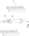
- This linear drive 8 is in FIG. 4 shown in more detail and comprises a spindle 8A, which can be rotated by a motor which is attached to both sides of the support device 5.
- the spindle carries a nut 8 B, which is connected to the support device 6.
- motor spindle rotation the mother and support device 6 is moved between two end positions. In this case, the support device 6 is guided in or on the vertical rails 7, which connect the two support elements of the support device 5 at the outer edges.
- the supporting device 5 comprises two clamping devices of a plurality of components, wherein a clamping device is arranged on the upper support element 5A and one on the lower support element 5B.
- the support device 6 also has two tensioning devices.
- Each clamping device comprises a band element 9.
- Each band element can - like FIG. 1 shows - are wrapped around the outer circumference of a mast 1 and is at least in the clamped state of this.
- the band ends of each band element 9 are formed by recesses and disposed therein sliding sleeve 10 is guided in the interior of a support device 5/6 and up there each end on its own winding roll 11 or unwound.
- the band member 9 is deflected in its direction by means of a guide roller 27.
- the pulleys have a smaller distance than the winding rollers.
- the support devices in turn each have contact elements 12, which in FIG. 8 are shown and their surfaces 12A can create here tangetial to the surface of a mast / tower.
- Prismatic bodies 12B have on one of their prism surfaces the contact surface 12A or abutment surfaces 12A and are here by a drive from the support device 5/6 pushed towards the mast or pulled away from this.
- push rods 12C can be used, to which a drive couples.
- the movement of the climbing robot is carried out such that one of the support devices 5/6 is braced on the mast / tower 1 by extending the contact elements in the direction of the mast and winding the band members 9 of this support device, thereby reducing the area enclosed by the band member 9 cross-section and so fixed a mast is enclosed.
- bracing the other support device is achieved by unwinding the tape from the winding rollers 11 and retracting the contact elements 12th
- linear drive 8 With the linear drive 8, the dissolved support device is moved relative to the fixed support device linearly in the vertical direction up or down.
- linear drives 13 are extended or extended, which the band elements. 9 connect various support devices.
- the linear drives 13 are preferably arranged only in the side facing away from the support devices 5/6 cross-sectional halves.
- the shifted support device is then braced and solved the previously strained and tracked in the same way.
- FIG. 7 shows a possible mechanism of a drive of the winding rollers 11.
- the winding shafts may have a latching mechanism 15A which is free-running only in one direction of rotation, namely that which causes a tension of a band element 9.
- a latching element 15B which blocks the reverse rotation of the shaft 15, is disengaged by means of an actuator (not shown here). This ensures that in the event of a power failure an existing tension will not be released.
- FIG. 9 shows a trolley 17, which is distributed in multiple identical design on the band member 9 distributed over the circumference of the mast.
- a portion of the band member 9 is received and the sleeve 18, thus the band member 9 is secured via a tension spring 20 to a bridge member 19 that the band member 9 bridges vertically, the ends of which have rollers on the surface of the mast / tower when a support device with the loosened belt element 9 is moved.
Landscapes
- Engineering & Computer Science (AREA)
- Architecture (AREA)
- Mechanical Engineering (AREA)
- Combustion & Propulsion (AREA)
- Chemical & Material Sciences (AREA)
- Structural Engineering (AREA)
- Civil Engineering (AREA)
- Sustainable Development (AREA)
- Life Sciences & Earth Sciences (AREA)
- Sustainable Energy (AREA)
- General Engineering & Computer Science (AREA)
- Transportation (AREA)
- Wind Motors (AREA)
Description
- Die Erfindung betrifft einen Kletterroboter für Masten, insbesondere für Windkraftanlagen, umfassend wenigstens eine erste Tragvorrichtung und wenigstens eine zweite Tragvorrichtung, wobei der Abstand der Tragvorrichtungen zueinander mittels wenigstens eines Linearantriebs in vertikaler Richtung änderbar ist und jede Tragvorrichtung wenigstens eine Spannvorrichtung umfasst, mittels der die jeweilige Tragvorrichtung am Mast festspannbar und vom Mast lösbar ist, wobei zumindest ein Teil der Spannvorrichtungen, bevorzugt jede der Spannvorrichtungen wenigstens ein Bandelement umfasst, das sich zwischen zwei an der Tragvorrichtung angeordneten Anlage- oder Befestigungsstellen erstreckt und in Umfangsrichtung flexibel um einen Mast/Turm herumlegbar und an dessen Mantelfläche anlegbar ist und wenigstens einen Spannantrieb umfasst, mit dem die Länge des wenigstens einen Bandelementes zwischen den Anlage- oder Befestigungsstellen vergrößerbar und verkleinerbar ist.
- Ein Kletterroboter dieser gattungsgemäßen Art kann z.B. bei Windkraftanlagen zum Einsatz kommen, um an dem Mast (ggfs. auch als Turm bezeichnet) einer Windkraftanlage herauf- oder herabzuklettern, z.B. zu Wartungszwecken. Erfindungsgemäß ist die Anwendung jedoch nicht auf Windkraftanlagen und deren Masten beschränkt. Ein erfindungsgemäßer Kletterroboter kann vielmehr an jeglichem Mast klettern, unabhängig davon, was von dem Mast getragen ist oder um was für einen Mast es sich handelt.
- Sofern demnach im Folgenden die Anwendung der Erfindung hinsichtlich Kletterroboter am Beispiel einer Windkraftanlage beschrieben wird, ist dies nicht als Einschränkung zu verstehen, sondern nur als mögliches, stellvertretend auch für andere Anwendungsfälle genanntes Beispiel zu sehen.
- Windkraftanlagen sind zu einem wichtigen Bestandteil unserer Energieversorgung geworden. Die Windkrafttechnologie unterliegt wie alle anderen Technologien (z.B. Luftfahrt, Raumfahrt oder Automobil etc.) bestimmten Anordnungen hinsichtlich Entwicklung, Produktion, Betrieb und Instandhaltung.
- Dabei wird dem sicheren Betrieb und der sicheren Instandhaltung besondere Aufmerksamkeit gewidmet. Hier sind insbesondere die periodischen Inspektionen der Rotorblätter und der Windtürme (Masten) zu nennen. Gleiche oder ähnliche Anforderungen gelten auch für andere Anlagenarten. Um diese Inspektionen ausführen zu können, braucht die Industrie bestimmte Anlagen, die alle Anforderungen von Funktionssicherheit bis Wirtschaftlichkeit der Instandhaltung als Komplettlösung erfüllen können.
- Die Anforderung der Wirtschaft und Technologie ist, möglichst viele Arbeitsschritte in einem Arbeitsgang am Ort des Betriebs, kostengünstig, schnell, präzise und sicher zu erledigen. Die dazu notwendigen heutigen Hilfsmittel eignen sich bisher nicht für einen solchen Vor-Ort-Einsatz. Unser Ansatz mit dieser Lösung ist genau diese Anforderungen mit diesem Kletterroboter zu erfüllen.
- Die Anforderung der periodischen Inspektion der Rotorblätter begrenzt sich nicht nur darauf, die sichtbaren Schäden zu beheben, sondern auch alle strukturellen Veränderungen wie Risse oder Delamination unter der Oberfläche (Lack) zu erkennen, bewerten und bei Bedarf zu beheben, damit ein sicherer Betrieb bis zur nächsten Inspektion gewährleistet werden kann. Um diesen Anforderungen zu genügen, müssen Arbeitsbedingung geschaffen werden, die den Einsatz geeigneter Prüfungs- und Reparaturmethoden (NDT, ZFP etc.) ermöglichen. Dabei ist wichtig an den Windkraftanlagen eine Arbeitsbedingung zu schaffen, damit viele Arbeitsschritte, die der Zeit in einer Reparaturhalle ausgeführt werden, Vorort zweckdienlich unabhängig der Wetterbedingungen durchgeführt werden können.
- Heute kann weder eine zerstörungsfreie Prüfung (ZFP) (None Destructive Testing (NDT)) noch eine Rotorblattreparatur am Windrad vollständig durchgeführt werden. Um aber den Kostendruck der Betreiber von Windkraftanlagen in einem wirtschaftlich effizienten Rahmen zu halten, müssen unbedingt die Ausfallzeiten minimiert werden. Das kann nur mit einer umfassenden Lösung für die Inspektion- und Reparatur an den Windkraftanlagen ermöglicht werden.
- Die periodisch geforderte Inspektion von Rotorblättern oder von Windkrafttürmen nach DIN EN 61400-23 (VDE 0127-23) verlangt aber eine lückenlose Untersuchung des Rotors auf weitere Schäden, die möglicherweise produktionsbedingt oder durch dynamische Belastung und häufig durch Betriebsvibration auftreten können. Die ZFP am Rotorblatt erweist sich durchaus schwierig aber wie in der Dissertation von Frau Dr.-Dipl.-Geophys. Anne Jüngert beschrieben, gibt es Möglichkeiten ZFP am Blatt durchführen zu können.
- Ein Kletterroboter der eingangs genannten gattungsgemäßen Art ist aus der Publikation
WO 2006/077358 A1 bekannt. Hier werden Spannbacken mittels durch Winden betätigten Spannseilen an einem Mast verspannt. Die Haltekräfte werden maßgeblich über die Spannbacken auf den Mast ausgeübt und nur zum Teil über die am Umfangsbereich des Mastes anliegenden Spannseile. Beim Klettern müssen die Spannseile mit den Spannbacken vom Mast abgehoben werden. - Ein weiterer Kletterroboter ist aus der Veröffentlichung
DE 10 2005 053 782 B4 bekannt. Die Spannvorrichtung wird hier durch Traversen gebildet, die gegeneinander verschiebbar sind und mit denen Spannträger / Spannpratzen an mehreren Stellen gegen die Mastoberfläche gedrückt werden, um Haftkräfte zwischen Kletterroboter und Mast zu erzeugen. - Hier ist es als nachteilig zu bewerten, dass der Kletterroboter sein Einsatzgebiet nur bei bestimmten vorgegebenen Mastdurchmessern hat und ansonsten in den Dimensionen umkonstruiert werden müsste und dass die haltenden Kräfte in diesem Fall mit jeweils nur 4 um den Umfang eines Mastes verteilten Spannträgern / Spannpratzen aufgebracht wird.
- Aufgabe der Erfindung ist es einen Kletterroboter bereit zu stellen, der eine hohe Einsatzflexibilität aufweist, hohe Sicherheit und Stabilität aufweist und an einer Vielzahl unterschiedlicher Masten oder Türme zum Einsatz kommen kann. Weiterhin ist es die Aufgabe auf eine einfache Weise die Bandelemente längs eines Mastes / Turmes zu verschieben.
- Gelöst wird die Aufgabe erfindungsgemäß mit einem Kletterroboter der eingangs genannten Art, bei dem an einem Bandelement, insbesondere einem jeweiligen Bandelement wenigstens ein Rollwagen oder Gleitwagen angeordnet ist, insbesondere über den Umfang verteilt mehrere Rollwagen oder Gleitwagen angeordnet sind, mit dem/denen ein Bandelement bei einem Lösen der Verspannung von der Mast.-/Turmoberfläche abhebbar ist.
- Wesentlich bei dieser Ausführung eines Kletterroboters ist es, dass die haltenden Kräfte nicht nur "punktuell" mit ein paar wenigen Spannträgern / Spannpratzen auf die Umfangsfläche eines Mastes oder eines Turmes aufgebracht werden, sondern, dass die Kräfte über einen wesentlichen Teil des gesamten Umfangs eingeleitet werden, was dadurch erzielt wird, dass in Umfangsrichtung flexible, also z.B. biegbare oder gelenkig verstellbare Bandelemente um den Mast oder Turm herum gelegt werden. Aufgrund der Flexibilität legt sich demnach ein Bandelement einer erfindungsgemäßen Spannvorrichtung an die Mantelfläche eines Mastes oder Turmes an.
- Dies hat auch den Vorteil, dass ein erfindungsgemäßer Kletterroboter nicht hinsichtlich der konkreten Querschnittsform des Mastes oder Turmes angepasst werden muss, weil eine solche Anpassung im jeweiligen Einzelfall automatisch aufgrund der Flexibilität der Bandelemente erfolgt. Hierdurch ist es auch problemlos möglich, an Masten zu klettern, deren Querschnitt sich entlang der Erstreckung ändert, z.B. konisch ist und im Durchmesser ändert.
- Der mit einem erfindungsgemäßen Kletterroboter umschlossene Querschnitt, in dem ein Mast oder Turm beim Klettern einliegt, ergibt sich zwischen den jeweiligen Bandelementen und den Tragvorrichtungen. Hierbei werden die Tragvorrichtungen in einen verspannten Zustand an die Mast- oder Turmmantelfläche herangezogen, wobei weiterhin ausgehend von einer Anlenk- oder Befestigungsstelle an einer Tragvorrichtung ein Bandelement um den Mast/Turm herumgelegt wird und wieder an einer Anlenk- oder Befestigungsstelle zur Tragvorrichtung geführt wird.
- Der größte Teil des insgesamt durch Tragvorrichtung und Bandelemente/n umschlossenen Querschnitts wird demnach vom Bandelement gebildet, so dass die wirkenden Kräfte zum Halten durch wesentlich größere Flächen auf den Mast/Turm aufgebracht werden als im Stand der Technik. Hier ist die wirkende Fläche gegeben durch die Höhe eines Bandelementes und die Länge des Kontaktes zwischen Bandelement und Mast/Turmoberfläche, sowie die Fläche, in der ein jeweiliges Tragelement anliegt. Die Haftreibung wird demnach gegenüber dem Stand der Technik signifikant erhöht.
- Eine Verspannung einer Tragvorrichtung des Kletterroboters kann dadurch erfolgen, dass mit einem Spannantrieb die Länge eines oder mehrerer Bandelemente verkürzt wird, insbesondere die effektiv wirkende Länge eines Bandelementes zwischen den Anlenk- oder Befestigungsstellen, insbesondere so dass hierdurch die dem Turm / Mast zuweisende Innenfläche eines jeweiligen Bandelementes an die Mantelfläche des Turmes / Mastes herangezogen wird und diese kontaktiert. Bevorzugt werden demnach die zum Halten notwendigen Kräfte überwiegend durch den direkten Kontakt zwischen Bandelement und Mantelfläche aufgebracht.
- Bei einer Tragvorrichtung, bei welcher der wenigstens eine Spannantrieb außerhalb der Tragvorrichtung liegt, also z.B. nicht eingehaust ist, kann eine solche vorgenannte Anlenk- oder Befestigungsstelle z.B. direkt durch ein Antrieb oder einen Teil davon gebildet werden, z.B. durch eine Wickelrolle, eine Umlenkrolle oder ähnliches.
- Es kann in einer bevorzugten Ausführung auch vorgesehen sein, dass wenigstens ein Spannantrieb im Inneren einer Tragvorrichtung angeordnet ist. Die Tragvorrichtung kann somit eine Einhäusung des wenigstens einen Spannantriebs bilden oder eine solche Einhäusung umfassen. Es werden sodann für jedes Bandelement zwei Ausnehmungen vorgesehen sein, an denen ein Bandelement in die Tragvorrichtung ein- bzw. aus dieser austritt. Das jeweiliges Bandelement reicht durch die Ausnehmungen in das Innere der Tragvorrichtung hinein, und wird im inneren durch den wenigstens einen Spannantrieb gespannt oder entlastet bzw. entspannt. Mit dem wenigstens einen Spannantrieb wird somit die außerhalb der Tragvorrichtung liegende Länge des Bandelementes vergrößerbar oder verkleinerbar. Hinter einer solchen vorgenannte Ausnehmung kann hier eine Anlenkstelle im Inneren der Tragvorrichtung liegen. Die Ausnehmung kann durch eine Gleithülse gebildet sein, durch die ein Bandelement hindurchgleiten kann, ggfs. sogar anlagefrei ist.
- Die grundsätzliche Kletterfunktion wird dadurch bewirkt, dass eine Tragvorrichtung mit der wenigstens einen Spannvorrichtung am Mast/Turm durch Verspannung, insbesondere somit Längenverringerung des wenigstens einen Bandelementes befestigt wird. Die nicht verspannte, somit zum Mast/Turm lose Tragvorrichtung wird mit wenigstens einem Linearantrieb in die gewünschte Bewegungsrichtung verschoben, also nach oben oder nach unten. Nach dieser Verschiebung wird die gerade verschobene Tragvorrichtung durch Verspannung befestigt und die zuvor verspannte Tragvorrichtung gelöst. Die dann gerade gelöste Tragvorrichtung kann mit dem wenigstens einen Linearantrieb in der gewünschten Bewegungsrichtung nachgeführt werden. Somit ergibt sich eine Art Schreitantrieb, bei dem die Tragvorrichtungen wechselweise verspannt, gelöst und linear verschoben werden.
- Die lineare Verschiebung kann durch wenigstens einen linearen Antrieb erfolgen mit dem der vertikale Abstand zwischen den wenigstens zwei Tragvorrichtungen, insbesondere zwischen einer Minimal- und Maximalstellung geändert werden kann. Beispielsweise kann ein solcher Antrieb als ein Spindelantrieb mit einer Gewindespindel ausgebildet sein, wobei die Spindel durch einen Motor in einer Tragvorrichtung gedreht wird und die andere Tragvorrichtung an einer auf der Spindel laufenden Mutter befestigt ist. Eine solche Spindel kann bevorzugt selbsthemmend sein. Der Antrieb kann auch durch ein hydraulisch oder pneumatisch arbeitendes Zylinder-Kolben-Aggregat ausgebildet sein, das abwechselnd mit Druck beaufschlagt und entlastet wird. Ebenso sind Zahnstangenantriebe möglich oder sonstige Antriebs-Ausführungen, die eine lineare Bewegung in vertikaler Richtung zwischen den Tragvorrichtungen bewirken.
- In einer einfachsten Ausführung kann es vorgesehen sein, dass ein Bandelement einer Tragvorrichtung einseitig ortsfest mit der Tragvorrichtung verbunden ist und das anderen Ende oder ein anderer Bereich lose befestigt ist, das heißt, dass an diesem losen Ende / Bereich ein Antrieb wirkt bzw. angreift, um die Spannung aufzubauen oder zu lösen. Diese konstruktiv einfache Ausgestaltung hat lediglich den Nachteil dass bei einem Verspannungs- und Lösungsvorgang der Kletterroboter um die Mast/Turm herumläuft. Dem könnte in der Summe aller Verspannungs- und Lösungsvorgänge entgegen gewirkt werden, wenn die Bandelemente der verschiedenen Tragvorrichtungen an verschiedenen Seiten ortfest befestigt sind und sich somit das Herumlaufen bei den beiden Tragvorrichtungen gegenläufig ist. Ebenso könnte eine Kompensation erzielt werden, wenn an einer Tragvorrichtung zwei Bandelemente in der Spannvorrichtung vorgesehen sind, die an gegenüberliegenden Seiten ihre ortsfesten und beweglichen Enden haben.
- In besonders bevorzugter Ausgestaltung kann es vorgesehen sein, dass ein Bandelement, insbesondere im Inneren einer Tragvorrichtung zwei Bandbereiche oder zwei Bandenden aufweist, an denen ein gemeinsamer Antrieb wirkt, insbesondere durch ein Ziehen/Schieben oder Auf-/Abwickeln des Bandelementes oder jeweils ein separater Antrieb wirkt, insbesondere durch ein Ziehen/Schieben oder Auf-/Abwickeln des Bandelementes. Hierbei kann jedes Bandelement einer Tragvorrichtung seinen eigenen Antrieb bzw. seine eigenen Antriebe aufweisen, es kann jedoch auch vorgesehen sein, dass bei mehreren Bandelementen an einer Tragvorrichtung alle Bandelemente einen Antrieb haben oder alle Bandelemente an ihren auf gleicher Seite liegenden Bandenden / Bandbereichen gemeinsame Antriebe haben.
- Bei den vorgenannten Ausführungen, bei denen beide Bandbereiche bzw. Bandenden eines Bandelements angetrieben sind, kann bewirkt werden, dass an den beiden Enden gleichzeitig die Verspannung erzeugt oder gelöst wird. Ein Herumlaufen des Kletterroboters um den Mast / Turm wird so verhindert.
- Ein Herumlaufen kann jedoch auch bewusst erzeugt werden, wenn von den beiden grundsätzlich antreibbaren Bereichen /Enden bei einem aktuellen Verspannungs- oder Lösungsschritt nur ein Bereich / Ende angetrieben wird.
- Wenn die Bandenden / Bandbereiche durch einen gemeinsamer Antrieb angetrieben werden, kann dies z.B. mit einer umschaltbaren Kupplung realisiert werden, mit der z.B. durch Ansteuerung einstellbar ist, ob der gemeinsame Antrieb an dem einem oder anderen der beiden Bandbereiche / Bandenden oder an beiden gleichzeitig wirkt.
- Bei separaten Antrieben für die Bandenden / Bandbereiche eines Bandelementes hingegen kann nur einer der Antriebe angesteuert werden, um ein Herumlaufen um den Mast zu bewirken, ansonsten jedoch arbeiten beide Antriebe synchron.
- Die Antriebe können z.B. Zahnräder antreiben, deren Zähne in Ausnehmungen der Bandelemente eingreifen, um Zug- oder Schubkräfte aufzubringen und so ein Spannen oder Lösen zu bewirken.
- Eine konstruktive einfache Ausgestaltung ergibt sich, wenn mit dem wenigstens einen Spannantrieb wenigstens eine Wickelrolle angetrieben wird, auf der das jeweilige Bandelement aufgewickelt wird, um ein Verspannen zu erzeugen oder abgewickelt wird, um ein Lösen zu erzeugen.
- Bei zwei angetriebenen Bandenden eines Bandelementes können in einer Ausführung beide Bandenden auf einer gemeinsamen Wickelrolle auf- und abgewickelt werden. Es kann auch vorgesehen sein, für jedes Bandende eine eigene Wickelrolle vorzusehen, insbesondere wobei die beiden Wickelrollen einen gemeinsamen oder getrennte Spannantriebe haben, wie zuvor erwähnt.
- In einer bevorzugten Weiterbildung, insbesondere der Ausführungen mit Wickelrollen kann es vorgesehen sein, dass das Band jeweils vor dem Bandbereich oder dem Bandende, an dem der wenigstens eine Antrieb wirkt, in seiner Erstreckungsrichtung an einer jeweiligen Umlenkstelle, insbesondere im Inneren der Tragvorrichtung, umgelenkt ist. Für diese Umlenkung kann z.B. eine Umlenkrolle zum Einsatz kommen.
- Diese Ausführung hat den Vorteil, dass zwischen zwei den jeweiligen Bandbereichen / Bandenden zugeordneten Umlenkrollen ein kleinerer Abstand, insbesondere ein kleinerer Abstand in Umfangsrichtung des Mastes / Turmes realisierbar ist als zwischen den Wickelrollen oder sonstigen Antriebselemente zum Spannen / Lösen.
- Es kann so bewirkt werden, dass der von einem Bandelement zwischen den Umlenkstellen umschlossene Querschnitt über mehr als 300 Grad, bevorzugt mehr als 330 Grad geschlossen ist. Ein Bandelement kann daher mit dieser Weiterbildung über eine größere Länge am Umfang eines Mastes oder Turmes anliegen.
- Um eine sichere und definierte Anlage einer jeweiligen Tragvorrichtung an seiner zu einem Mast/Turm weisenden Seite bei einer Verspannung zu erzielen kann es vorgesehen sein, dass eine jeweilige Tragvorrichtung wenigstens zwei in Umfangsrichtung eines Mastes/Turmes beabstandete Anlageelemente aufweist, mittels denen eine Tragvorrichtung bei einem Spannvorgang an der äußeren Mast-/Turmfläche abstützbar ist. Diese Anlageelemente können z.B. Anlageflächen haben, die z.B. tangential an die Mast- oder Turmoberfläche anlegbar sind. Ebenso kann es vorgesehen sein, die Anlageflächen gekrümmt, z.B. als Teilzylinderfläche auszubilden.
- In einer Weiterbildung kann es hier vorgesehen sein, dass jedes der Anlageelemente in Richtung auf die Mast-/Turmoberfläche und zurück bewegbar ist, insbesondere dass alle gleichzeitig bewegbar sind. Für diese Bewegungsmöglichkeit können die Anlageelemente wenigstens einen, z.B. einen gemeinsamen Antrieb oder auch getrennte Antriebe aufweisen, mit denen die Anlageelemente von einer Tragvorrichtung in Richtung zum Mast / Turm bewegbar und zurückziehbar sind.
- Z.B. wenn eine Tragvorrichtung vom Turm / Mast gelöst wird, um diese mit dem wenigstens einen Linearantrieb in der vertikalen Richtung zu bewegen, können so vor der Bewegung mit dem wenigstens einen Antrieb der Anlageelemente diese von der Mast- / Turmoberfläche weggezogen werden, so dass eine Tragvorrichtung bei ihrer vertikalen Bewegung zum Mast / Turm anlagefrei ist. Vor oder während einer Verspannung können die Anlageelement sodann an die Oberfläche des Mastes / Turm durch eine darauf zugerichtete Bewegung angestellt werden.
- Es kann hier weiterhin vorgesehen sein dass der Abstand der Anlageelemente in Umfangsrichtung des Mastes/Turmes größer ist als der Abstand der Umlenkstellen des Bandelementes bei einer Kombination der diesbezüglichen Ausführungsvarianten.
- In bevorzugter Weiterbildung, die mit jeder der vorgenannten Ausführungen kombinierbar ist können zwei Bandelemente verschiedener Tragvorrichtungen mittels ansteuerbarer, in der Länge änderbarer Linearantriebe verbunden sein, insbesondere auf einer von den Tragvorrichtungen wegweisenden Seite eines Mastes/Turmes. Ein Bandelement einer aktuell nicht verspannten Tragvorrichtung kann so gegen den Herabrutschen am Mast / Turm in Schwerkraftrichtung gesichert werden, da es über den in der Länge änderbaren Linearantrieb zusätzlich an einem Bandelemente befestigt ist, dass aktuell verspannt und somit am Mast / Turm fest ist.
- Wird die gelöste Tragvorrichtung in vertikaler Richtung bewegt durch eine Ansteuerung des die Tragvorrichtungen verbindenden Linearantriebs, so kann gleichzeitig auch eine Ansteuerung des oder der die Bandelemente der verschiedenen Tragvorrichtungen verbindenden Linearantriebe erfolgen, so dass diese ihre Länge synchron zueinander und zu dem wenigstens einen Linearanrieb der Tragvorrichtungen ändern, also verringern oder vergrößern je nach Bewegungsrichtung. So werden auch die maximal von den Tragvorrichtungen entfernten Bandelementbereiche gegen die Schwerkraft gestützt und in Bewegungsrichtung der losen Tragvorrichtung mitbewegt.
- Erfindungsgemäß ist es vorgesehen, dass an einem jeweiligen Bandelement wenigstens ein Rollwagen oder Gleitwagen angeordnet ist, insbesondere über den Umfang verteilt mehrere Rollwagen oder Gleitwagen angeordnet sind, mit dem/denen ein Bandelement bei einem Lösen der Verspannung von der Mast.-/Turmoberfläche abhebbar ist. Ein solches Abheben des Bereiches eines Bandelementes, in welchem ein solcher Wagen angeordnet ist, kann z.B. durch eine konstante Kraftbeaufschlagung erfolgen, welche das Bandelement zum Wagen zieht, wenn die Verspannung im Bandelement gelöst wird. Ein gelöstes und abgehobenes Bandelement kann sodann einfacher längs des Mastes / Turmes verschoben werden, wobei bevorzugt nur der jeweilige Wagen auf der Mast-/Turmoberfläche rollt oder gleitet.
- Ein Rollwagen oder Gleitwagen kann z.B. ein Brückenelement aufweisen, welches ein Bandelement in vertikaler Richtung überbrückt und mit seinen beiden Enden mittels dort angebrachter Rollen oder Gleitsteinen an eine Mast-/Turmoberfläche anlegbar/angelegt ist, wobei die zum Mast/Turm weisende Seite des Brückenelementes mittels einer Zugfeder mit dem Bandelement verbunden ist. Diese Verbindung kann z.B. erzeugt sein durch eine Hülse, an der die Zugfeder befestigt ist und in der das Bandelement einliegt.
- Die Kletterfunktion eines erfindungsgemäßen Kletterroboters ist bereits dann sichergestellt, wenn zwei Tragvorrichtungen in vertikaler Richtung übereinander angeordnet sind. Ein stabilere Anordnung kann erzielt werden, wenn die beiden Tragvorrichtung ineinander verschränkt angeordnet sind.
- Dies kann z.B. dadurch erzielt werden, dass wenigstens eine der beiden Tragvorrichtungen wenigstens zwei in vertikaler Richtung zueinander beabstandete und untereinander verbundene Tragelemente aufweist, wobei jedes der Tragelemente wenigstens eine Spannvorrichtung aufweist und zwischen zwei solchen Tragelementen die andere der beiden Tragvorrichtungen vollständig oder mit zumindest einem von mehreren in vertikaler Richtung zueinander beabstandeten und untereinander verbundenen Tragelementen angeordnet ist.
- Beispielsweise können dabei zwei Tragelemente von einer der Tragvorrichtungen durch vertikale Schienen miteinander verbunden sind, an denen die andere Tragvorrichtung oder eines von mehreren Tragelementen der anderen Tragvorrichtung geführt ist.
- Ein Bandelement, welches hier zum Einsatz kommen kann, kann z.B. ausgebildet sein als ein Gliederband mit mehreren Bandgliedern, die um eine vertikale Achse schwenkbar miteinander verbunden sind, z.B. auch eine Kette oder durch ein Flachband aus einem Metall oder einem Faser-Kunststoff-Verbund oder besonders bevorzugt als ein textiles Band, insbesondere ein Gurt.
- Ein textiles Bandelement hat den Vorteil, dass durch die Verwebung der einzelnen Bandfasern eine Flexibilität nicht nur in Umfangsrichtung erreicht wird, sondern auch in vertikaler Richtung. Ein solches textiles Bandelement kann sich somit besonders gut auch an Masten oder Türme anlegen, die in vertikaler Richtung konisch geformt sind, da sich an einem textilen Bandelement um unteren Umfangsbereich problemlos eine andere den Mast / Turm kontaktierende Umfangslänge einstellen kann also am oberen Bereich. Ein textiles Bandelement formt sich somit an eine Konizität problemlos an. Dies ist besonders vorteilhaft bei Windkraftanlagen, die üblicherweise konische Türme haben.
- Ausführungsformen der Erfindung werden nachfolgend anhand von Figuren beschrieben. Es zeigen:
- Figur 1:
- eine Windkraftanlage mit einem erfindungsgemäßen Kletterroboter und einer daran befestigten mobilen Wartungshalle
- Figur 2:
- den Kletterroboter mit Wartungshalle in Aufsicht auf die Mast-/Turmseite
- Figuren 3:
- mehrere Ansichten des Kletterroboters mit Wartungshalle
- Figur 4:
- den Linearantrieb der Tragvorrichtungen
- Figuren 5:
- eine Spannvorrichtung eines von zwei Tragelementen der einen Tragvorrichtung
- Figuren 6:
- die Spannvorrichtungen der anderen Tragvorrichtung
- Figur 7:
- einen Antrieb einer Spannvorrichtung
- Figur 8:
- die Anlageelemente einer Tragvorrichtung
- Figur 9:
- einen an Bandelementen anbringbaren Rollwagen
- Die
Figur 1 zeigt in einer Übersicht die mögliche Anwendung eines erfindungsgemäßen Kletterroboters mit einer daran befestigten Wartungshalle bei einer Windkraftanlage mit einem Mast 1 bzw. Turm 1, an dem der Kletterroboter schreiten, d.h. nicht-kontinuierlich herauf- oder herabklettern kann, z.B. um Wartungsarbeiten an einem Rotorblatt 2 vornehmen zu können. - Die
Figuren 2 und3 zeigen den Kletterroboter 3 und die Wartungshalle 4 in detaillierterer Darstellung. - Der Kletterroboter 3 umfasst eine erste Tragvorrichtungen 5 und eine zweite Tragvorrichtung 6. Die erste Tragvorrichtung 5 ist unterteilt in zwei Tragelemente 5A und 5B die in vertikaler Richtung beabstandet und durch Führungsschienen 7 verbunden sind, an denen die Tragvorrichtung 6 geführt ist, die zwischen den Tragelementen 5A und 5B mit einem Linearantrieb 8 auf- und abbewegt werden kann. Dieser Linearantrieb 8 ist in
Figur 4 detaillierter dargestellt und umfasst eine Spindel 8A, die durch einen Motor gedreht werden kann die beidseits an der Tragvorrichtung 5 befestigt ist. Die Spindel trägt eine Mutter 8B, die mit der Tragvorrichtung 6 verbunden ist. Durch motorische Spindeldrehung wird die Mutter und Tragvorrichtung 6 verschoben zwischen zwei Endstellungen. Dabei ist die Tragvorrichtung 6 in oder an den vertikalen Schienen 7 geführt, die die beiden Tragelemente der Tragvorrichtung 5 an den äußeren Kanten verbinden. - Die Tragvorrichtung 5 umfasst zwei Spannvorrichtungen aus mehreren Bauelementen, wobei eine Spannvorrichtung an dem oberen Tragelement 5A und eine an dem unteren Tragelement 5B angeordnet ist. Die Tragvorrichtung 6 hat ebenso zwei Spannvorrichtungen.
- Gemäß den
Figuren 5 und6 umfasst jede Spannvorrichtung ein Bandelement 9. Jedes Bandelement kann - wieFigur 1 zeigt - um den äußeren Umfang eines Mastes 1 herumgelegt werden und liegt zumindest im verspannten Zustand an diesem an. Um das Erzeugen der Spannung sowie das Lösen der Spannung zu bewirken werden die Bandenden jedes Bandelementes 9 durch Ausnehmungen und darin angeordnete Gleithülsen 10 in das Innere einer Tragvorrichtung 5/6 geführt und dort jedes Ende auf einer eigenen Wickelrolle 11 auf- oder abgewickelt. - Örtlich zwischen einer Gleithülse 10 und einer Wickelrolle 11 wird das Bandelement 9 in seiner Richtung mittels einer Umlenkrolle 27 umgelenkt. Die Umlenkrollen haben einem geringeren Abstand als die Wickelrollen. Trotz der groß bauenden Wickelrollen 11 und der für deren Antrieb nötigen Bauteile kann so erreicht werden, dass ein Bandelement über einen Winkel α > 300 Grad am Umfang eines Mastes 1 anliegt, wie es
Figur 3 visualisiert. Hierdurch wird eine besonders große Kraftübertragungsfläche erzielt. - Die Tragvorrichtungen haben ihrerseits jeweils Anlageelemente 12, die in
Figur 8 gezeigt sind und deren Flächen 12A sich hier tangetial an die Oberfläche eines Mastes / Turm anlegen können. Prismenförmige Körper 12B weisen auf einer ihrer Prismenflächen die Anlagefläche 12A oder Anlageflächen 12A auf und sind hier durch einen Antrieb von der Tragvorrichtung 5/6 in Richtung zum Mast schiebbar oder von diesem wegziehbar. Hierfür können Schubstangen 12C verwendet werden, an denen ein Antrieb ankoppelt. - Die Bewegung des Kletterroboters erfolgt derart, dass eine der Tragvorrichtungen 5/6 am Mast / Turm 1 verspannt wird durch Ausfahren der Anlageelemente in Richtung zum Mast und Aufwickeln der Bandelemente 9 dieser Tragvorrichtung, wodurch der vom Bandelement 9 umschlossene Querschnitt verkleinert und so ein Mast fest umschlossen wird. Nach der Verspannung wird die andere Tragvorrichtung gelöst durch Abwickeln des Bandes von den Wickelrollen 11 und Einziehen der Anlageelemente 12.
- Mit dem Linearantrieb 8 wird die gelöste Tragvorrichtung relativ zur festen Tragvorrichtung linear in vertikaler Richtung nach oben oder unten verschoben. Dabei werden synchron zur Bewegungsweite der Tragvorrichtungen zueinander zusätzlich Linearantriebe 13 ein- oder ausgefahren, welche die Bandelemente 9 verschiedener Tragvorrichtungen verbinden. Hierdurch werden die losen Bandelemente 9 gegen die Schwerkraft in horizontaler Lage gehalten und mitbewegt. Die Linearantriebe 13 sind bevorzugt nur in der von den Tragvorrichtungen 5/6 abgewandter Querschnittshälften angeordnet.
- Die verschobene Tragvorrichtung wird sodann verspannt und die zuvor verspannte gelöst und in gleicher Weise nachgeführt.
- Die
Figur 7 zeigt eine mögliche Mechanik eines Antriebs der Wickelrollen 11. Mit einem Motor 14 werden über ein Getriebe zwei Wickelwellen 15 gleichzeitig angetrieben oder durch eine Kupplung 16 nur eine der Wickelwellen 15 an den Motor angekoppelt. Die Wickelwellen können einen Rastmechanismus 15A aufweisen, der nur in einer Drehrichtung freilaufend ist, nämlich derjenigen, die eine Verspannung eines Bandelementes 9 bewirkt. Für ein Lösen kann es vorgesehen sein, dass ein Rastelement 15B, welches die umgekehrte Drehung der Welle 15 blockiert, mittels eines Aktors (hier nicht gezeigt) außer Eingriff gebracht wird. So wird sichergestellt, dass bei einem Stromausfall eine bestehende Verspannung sich nicht löst. -
Figur 9 zeigt einen Rollwagen 17, der in mehrfacher gleicher Ausführung am Bandelement 9 über den Umfang des Mastes verteilt angebracht ist. In einer hier geschlitzten Haltehülse 18 ist ein Bereich des Bandelementes 9 aufgenommen und die Hülse 18, somit auch das Bandelement 9 über eine Zugfeder 20 an einer Brückenelement 19 befestigt, dass das Bandelement 9 vertikal überbrückt, wobei deren Enden Rollen aufweisen, die auf der Oberfläche des Mastes/ Turmes rollen, wenn eine Tragvorrichtung mit dem gelösten Bandelement 9 bewegt wird. - Bei Lösen und der nachlassenden Spannung im Bandelement 9 wird diese durch die ziehende Feder 20 von der Mastoberfläche abgezogen, so dass das Bandelement nur rollend weiterbewegt wird. Wird hingegen die Spannung durch Aufwickeln des Bandelementes mit den Wickelrollen 11 vergrößert, so wird das Bandelement gegen die Feder 20 auf die Manteloberfläche des Mastes / Turmes gezogen und liegt dort fest an, wobei die Feder 20 maximal gespannt ist für den nächsten Abziehvorgang.
Claims (15)
- Kletterroboter für Masten/Türme (1), insbesondere für Windkraftanlagen, umfassend wenigstens eine erste Tragvorrichtung (5) und wenigstens eine zweite Tragvorrichtung (6), wobei der Abstand der Tragvorrichtungen (5,6) zueinander mittels wenigstens eines Linearantriebs (7,8) in vertikaler Richtung änderbar ist und jede Tragvorrichtung (5,6) wenigstens eine Spannvorrichtung (9,10,11) umfasst, mittels der die jeweilige Tragvorrichtung (5,6) am Mast/Turm (1) festspannbar und vom Mast/Turm (1) lösbar ist, wobei zumindest ein Teil der Spannvorrichtungen (9,10,11), bevorzugt jede der Spannvorrichtungen (9,10,11) wenigstens ein Bandelement (9) umfasst, das sich zwischen zwei an der Tragvorrichtung (5,6) angeordneten Anlage- oder Befestigungsstellen (10,11) erstreckt und in Umfangsrichtung flexibel um einen Mast/Turm (1) herumlegbar und an dessen Mantelfläche anlegbar ist und wenigstens einen Spannantrieb (14) umfasst, mit dem die Länge des wenigstens einen Bandelementes (9) zwischen den Anlage- oder Befestigungsstellen (10,11) vergrößerbar und verkleinerbar ist, dadurch gekennzeichnet, dass an einem Bandelement (9), insbesondere einem jeweiligen Bandelement wenigstens ein Rollwagen (17) oder Gleitwagen angeordnet ist, insbesondere über den Umfang verteilt mehrere Rollwagen (17) oder Gleitwagen angeordnet sind, mit dem/denen ein Bandelement (9) bei einem Lösen der Verspannung von der Mast.-/Turmoberfläche abhebbar ist.
- Kletterroboter nach Anspruch 1, dadurch gekennzeichnet, dass ein Rollwagen (17) oder Gleitwagen ein Brückenelement (19) aufweist, das ein Bandelement (9) in vertikaler Richtung überbrückt und mit seinen beiden Enden mittels dort angebrachter Rollen oder Gleitsteinen an eine Mast-/Turmoberfläche anlegbar/angelegt ist und die zum Mast/Turm weisende Seite des Brückenelementes (19) mittels einer Zugfeder (20) mit dem Bandelement (9) verbunden ist, insbesondere mittels einer Hülse (18), an der die Zugfeder (20) befestigt ist und in der das Bandelement (9) einliegt.
- Kletterroboter nach einem der vorherigen Ansprüche, dadurch gekennzeichnet, dass die zum Halten wirkenden Kräfte auf den Mast/Turm (1) aufgebracht sind durch eine wirkende Fläche, die gegeben ist durch die Höhe eines jeweiligen Bandelementes und die Länge des Kontaktes zwischen jeweiligem Bandelement und Mast/Turmoberfläche, sowie die Fläche, in der eine jeweilige Tragvorrichtung am Mast/Turm (1) anliegt.
- Kletterroboter nach einem der vorherigen Ansprüche, dadurch gekennzeichnet, dass der wenigstens eine Spannantrieb (14) im Inneren einer Tragvorrichtung (5,6) angeordnet ist und ein jeweiliges Bandelement (9) durch Ausnehmungen in das Innere der Tragvorrichtung (5,6) hineinreicht, wobei mit dem wenigstens einen Spannantrieb (14) die außerhalb der Tragvorrichtung liegende Länge des Bandelementes (9) vergrößerbar oder verkleinerbar ist.
- Kletterroboter nach einem der vorherigen Ansprüche, dadurch gekennzeichnet, dass ein Bandelement (9), insbesondere im Inneren einer Tragvorrichtung (5,6) zwei Bandbereiche oder zwei Bandenden aufweist, an denena. ein gemeinsamer Antrieb (14) wirkt, insbesondere durch ein Ziehen/Schieben oder Auf-/Abwickeln des Bandelementes (9) oderb. jeweils ein separater Antrieb wirkt, insbesondere durch ein Ziehen/Schieben oder Auf-/Abwickeln des Bandelementes (9)insbesondere wobei jedes Bandelement (9) seinen eigenen Antrieb / seine eigenen Antriebe aufweist.
- Kletterroboter nach Anspruch 5, dadurch gekennzeichnet, dass ein gemeinsamer Antrieb (14) mittels einer umschaltbaren Kupplung (16) wahlweise an einem der beiden Bandbereiche / einem der beiden Bandenden oder an beiden gleichzeitig wirkt.
- Kletterroboter nach Anspruch 5 oder 6, dadurch gekennzeichnet, dass das Bandelement (9) jeweils vor dem Bandbereich oder dem Bandende, an dem der wenigstens eine Antrieb (14) wirkt, in seiner Erstreckungsrichtung an einer jeweiligen Umlenkstelle (27), insbesondere im Inneren der Tragvorrichtung (5,6), umgelenkt ist.
- Kletterroboter nach Anspruch 7, dadurch gekennzeichnet, dass der vom Bandelement (9) zwischen den Umlenkstellen (27) umschlossene Querschnitt des Turms/Mastes (1) über mehr als 300 Grad, bevorzugt mehr als 330 Grad geschlossen ist.
- Kletterroboter nach einem der vorherigen Ansprüche, dadurch gekennzeichnet, dass eine Tragvorrichtung (5,6) an seiner zu einem Mast/Turm (1) weisenden Seite wenigstens zwei in Umfangsrichtung eines Mastes/Turmes (1) beabstandete Anlageelemente (12) aufweist, mittels denen eine Tragvorrichtung (5,6) bei einem Spannvorgang an der äußeren Mast-/Turmfläche abstützbar ist.
- Kletterroboter nach Anspruch 9, dadurch gekennzeichnet, dass jedes der Anlageelemente (12), in Richtung auf die Mast-/Turmoberfläche und zurück bewegbar ist, insbesondere dass alle gleichzeitig bewegbar sind.
- Kletterroboter nach Anspruch 9 oder 10, dadurch gekennzeichnet, dass der Abstand der Anlageelemente (12) in Umfangsrichtung des Mastes/Turmes (1) größer ist als der Abstand der Umlenkstellen (27) des Bandelementes (9).
- Kletterroboter nach einem der vorherigen Ansprüche, dadurch gekennzeichnet, dass zwei Bandelemente (9) verschiedener Tragvorrichtungen (5,6) mittels ansteuerbarer, in der Länge änderbarer Linearantriebe (13) verbunden sind, insbesondere auf einer von den Tragvorrichtungen (5,6) wegweisenden Seite eines Mastes/Turmes (1).
- Kletterroboter nach einem der vorherigen Ansprüche, dadurch gekennzeichnet, dass wenigstens eine der beiden Tragvorrichtungen (5,6) wenigstens zwei in vertikaler Richtung zueinander beabstandete und untereinander verbundene Tragelemente (5A, 5B) aufweist, wobei jedes der Tragelemente (5A, 5B) wenigstens eine Spannvorrichtung (9,10,11) aufweist und zwischen zwei Tragelementen (5A, 5B) die andere der beiden Tragvorrichtungen (6) vollständig oder mit zumindest einem von mehreren in vertikaler Richtung zueinander beabstandeten und untereinander verbundenen Tragelementen angeordnet ist.
- Kletterroboter nach Anspruch 13, dadurch gekennzeichnet, dass zwei Tragelemente (5A, 5B) von einer der Tragvorrichtungen (5,6) durch vertikale Schienen (7) miteinander verbunden sind, an denen die andere Tragvorrichtung (6) oder eines von mehreren Tragelementen der anderen Tragvorrichtung (6) geführt ist.
- Kletterroboter nach einem der vorherigen Ansprüche, dadurch gekennzeichnet, dass ein Bandelement (9) ausgebildet ist als:c. ein Gliederband mit mehreren Bandgliedern, die um eine vertikale Achse schwenkbar miteinander verbunden sind oderd. ein Flachband aus einem Metall oder einem Faser-Kunststoff-Verbund odere. ein textiles Band, insbesondere ein Gurt
Priority Applications (1)
| Application Number | Priority Date | Filing Date | Title |
|---|---|---|---|
| EP15000598.1A EP2896823B1 (de) | 2012-01-31 | 2013-01-30 | Mobile wartungshalle für kletterroboter für masten |
Applications Claiming Priority (2)
| Application Number | Priority Date | Filing Date | Title |
|---|---|---|---|
| DE102012001725A DE102012001725A1 (de) | 2012-01-31 | 2012-01-31 | Kletterroboter für Masten |
| PCT/EP2013/000270 WO2013113494A2 (de) | 2012-01-31 | 2013-01-30 | Kletterroboter für masten |
Related Child Applications (2)
| Application Number | Title | Priority Date | Filing Date |
|---|---|---|---|
| EP15000598.1A Division-Into EP2896823B1 (de) | 2012-01-31 | 2013-01-30 | Mobile wartungshalle für kletterroboter für masten |
| EP15000598.1A Division EP2896823B1 (de) | 2012-01-31 | 2013-01-30 | Mobile wartungshalle für kletterroboter für masten |
Publications (2)
| Publication Number | Publication Date |
|---|---|
| EP2809946A2 EP2809946A2 (de) | 2014-12-10 |
| EP2809946B1 true EP2809946B1 (de) | 2018-03-07 |
Family
ID=47740890
Family Applications (2)
| Application Number | Title | Priority Date | Filing Date |
|---|---|---|---|
| EP15000598.1A Not-in-force EP2896823B1 (de) | 2012-01-31 | 2013-01-30 | Mobile wartungshalle für kletterroboter für masten |
| EP13705098.5A Not-in-force EP2809946B1 (de) | 2012-01-31 | 2013-01-30 | Kletterroboter für masten |
Family Applications Before (1)
| Application Number | Title | Priority Date | Filing Date |
|---|---|---|---|
| EP15000598.1A Not-in-force EP2896823B1 (de) | 2012-01-31 | 2013-01-30 | Mobile wartungshalle für kletterroboter für masten |
Country Status (5)
| Country | Link |
|---|---|
| US (1) | US9327784B2 (de) |
| EP (2) | EP2896823B1 (de) |
| DE (1) | DE102012001725A1 (de) |
| ES (1) | ES2672493T3 (de) |
| WO (1) | WO2013113494A2 (de) |
Cited By (1)
| Publication number | Priority date | Publication date | Assignee | Title |
|---|---|---|---|---|
| CN108516025A (zh) * | 2018-03-28 | 2018-09-11 | 李清花 | 一种自动爬杆装置 |
Families Citing this family (92)
| Publication number | Priority date | Publication date | Assignee | Title |
|---|---|---|---|---|
| CN103663309B (zh) * | 2013-11-12 | 2016-02-17 | 东莞市骏兴机械科技有限公司 | 卷型重物的电动伺服夹取移动系统 |
| CN103603774B (zh) * | 2013-11-18 | 2016-03-16 | 长春理工大学 | 一种风电自举升系统 |
| CN103692436B (zh) * | 2013-12-20 | 2016-05-04 | 马鞍山市力翔机械自动化科技有限公司 | 爬缆机器人 |
| CN103644084B (zh) * | 2013-12-23 | 2017-01-25 | 长春理工大学 | 一种分阶段举升方法 |
| ES2540790B1 (es) * | 2014-01-11 | 2016-04-20 | Cástor CASAS TOJO | Sistema de grúas autoescalables y autoajustables para aerogeneradores |
| US10384804B2 (en) * | 2015-04-14 | 2019-08-20 | ETAK Systems, LLC | Cell tower installation and maintenance systems and methods using robotic devices |
| CN105059415A (zh) * | 2015-08-06 | 2015-11-18 | 中国林业科学研究院林业新技术研究所 | 攀爬机器人 |
| CN105126316B (zh) * | 2015-09-20 | 2017-05-31 | 衢州妙凯节能科技有限公司 | 一种伸缩型管道攀爬机 |
| GB2542605B (en) * | 2015-09-25 | 2018-04-04 | Subsea 7 Ltd | Moving tools on offshore structures with a walking carriage |
| CN105253213A (zh) * | 2015-10-27 | 2016-01-20 | 昆明理工大学 | 一种爬杆机器人 |
| CN105345806B (zh) * | 2015-12-07 | 2017-10-27 | 中国石油大学(北京) | 自主升降监控机器人 |
| JP6154921B1 (ja) * | 2016-01-15 | 2017-06-28 | 日綜産業株式会社 | 風力発電装置におけるブレードのメンテナンス用ゴンドラ装置 |
| CN105947008B (zh) * | 2016-05-13 | 2018-02-16 | 陈奕冰 | 一种爬树机器人 |
| US10456906B2 (en) * | 2016-07-08 | 2019-10-29 | ETAK Systems, LLC | Mechanical tower climber for operations on cell towers |
| CN106112993B (zh) * | 2016-08-22 | 2018-02-06 | 常州信息职业技术学院 | 一种交替式爬杆机器人 |
| WO2018055217A1 (es) * | 2016-09-23 | 2018-03-29 | Leunamme Engineering S.L.U. | Procedimiento y equipo para la reposición de componentes de aerogeneradores |
| CN106347516B (zh) * | 2016-11-01 | 2024-03-26 | 新疆大学 | 一种气动爬杆机器人载物平台的设计 |
| CN108340364B (zh) * | 2017-01-24 | 2020-09-15 | 南京原觉信息科技有限公司 | 爬行机器装置与其部署方法 |
| CN106948593B (zh) * | 2017-02-28 | 2019-12-27 | 深圳市特辰科技股份有限公司 | 一种轮式机器人爬架 |
| CN107031747B (zh) * | 2017-03-28 | 2019-01-29 | 东南大学 | 一种变直径爬杆机器人 |
| WO2018184741A1 (en) * | 2017-04-05 | 2018-10-11 | Siemens Wind Power A/S | Parking assembly |
| WO2018204490A1 (en) * | 2017-05-02 | 2018-11-08 | Infrastructure Preservation Corporation | Robotic inspection system for high mast light poles |
| CN107472392B (zh) * | 2017-07-07 | 2023-04-07 | 武汉科技大学 | 一种轮式越障爬杆机器人 |
| CN107640242B (zh) * | 2017-09-21 | 2023-10-27 | 山东建筑大学 | 开合式结构的旋转载物平台和攀爬机器人 |
| US10919590B2 (en) * | 2017-09-21 | 2021-02-16 | Infrastructure Preservation Corporation | Robotic repair system for high mast light poles |
| CN107877426A (zh) * | 2017-12-14 | 2018-04-06 | 广东电网有限责任公司惠州供电局 | 一种杆塔倾斜监测专用传感器的夹具 |
| CN108252211B (zh) * | 2017-12-23 | 2024-03-26 | 香港中文大学(深圳) | 攀爬式检测机器人 |
| CN108644073B (zh) * | 2018-03-24 | 2020-03-13 | 北京工业大学 | 一种风力发电机塔筒的清洁机器人 |
| CN109455241B (zh) * | 2018-04-09 | 2020-09-29 | 国家电网公司 | 一种转位爬杆机构 |
| CN108725621A (zh) * | 2018-06-14 | 2018-11-02 | 广东珺桦能源科技有限公司 | 一种砍树机器人用的攀爬机构 |
| CN108555940B (zh) * | 2018-07-04 | 2020-07-07 | 南京原觉信息科技有限公司 | 爬行机器人及其爬杆结构 |
| CN108749945B (zh) * | 2018-07-27 | 2023-10-20 | 贵州电网有限责任公司 | 一种多功能电杆爬杆机器人 |
| CN108891499B (zh) * | 2018-07-27 | 2023-10-20 | 贵州电网有限责任公司 | 一种用于电杆爬杆机器人的夹紧装置 |
| CN109331431B (zh) * | 2018-09-21 | 2020-10-09 | 浙江宝纺印染有限公司 | 一种用于竖直杆稳定爬升运输的自动爬升装置 |
| CN109484505A (zh) * | 2018-11-21 | 2019-03-19 | 杨聪智 | 爬升单元及爬升装置 |
| CN109591906B (zh) * | 2019-01-28 | 2021-05-04 | 山东建筑大学 | 一种输电杆塔攀爬机器人控制系统及控制方法 |
| CN109895114B (zh) * | 2019-03-12 | 2024-02-27 | 广东机电职业技术学院 | 一种气动肌肉驱动的多边形结构的攀爬机器人 |
| CN109819798B (zh) * | 2019-03-15 | 2021-03-30 | 广西大学 | 一种利用自身重力增加爬升力的桉树修枝机 |
| CN110227241A (zh) * | 2019-04-28 | 2019-09-13 | 王清国 | 一种电力设施检修用电线杆攀爬工具 |
| CN110255430B (zh) * | 2019-06-20 | 2023-11-03 | 深圳市翠箓科技绿化工程有限公司 | 一种导轨攀爬机器人 |
| CN110254545B (zh) * | 2019-06-25 | 2024-07-23 | 北京史河科技有限公司 | 一种爬壁机器人 |
| US11117267B2 (en) | 2019-08-16 | 2021-09-14 | Google Llc | Robotic apparatus for operating on fixed frames |
| CN112524401B (zh) * | 2019-08-29 | 2024-04-30 | 临颍县爬杆机器人有限公司 | 一种收紧式载物平台 |
| CN112441153A (zh) * | 2019-08-29 | 2021-03-05 | 临颍县爬杆机器人有限公司 | 一种爬杆机器人 |
| ES3014258T3 (en) * | 2019-09-05 | 2025-04-21 | Pp Energy Aps | Blade access arrangement for a rotor blade of a wind power plant |
| CN110952443B (zh) * | 2019-11-21 | 2024-07-02 | 深圳市人工智能与机器人研究院 | 一种分体式缆索攀爬检测机器人 |
| CN110757319A (zh) * | 2019-11-25 | 2020-02-07 | 沈阳工业大学 | 具备爬行功能的立柱油漆自动清理打磨机 |
| CN111113441B (zh) * | 2019-12-13 | 2023-02-03 | 国网浙江嘉善县供电有限公司 | 一种带电作业机器人移动装置 |
| CN110893977B (zh) * | 2019-12-16 | 2021-06-04 | 华能山东发电有限公司众泰电厂 | 一种发电设备安装用配件运输装置 |
| CN111173692A (zh) * | 2019-12-31 | 2020-05-19 | 上海扩博智能技术有限公司 | 用于风机叶片的检修工具挂载装置 |
| CN111232080B (zh) * | 2020-03-12 | 2021-01-12 | 国网安徽省电力有限公司电力科学研究院 | 一种环抱式爬杆机器人 |
| CN111330895B (zh) * | 2020-04-07 | 2024-08-02 | 机械科学研究总院海西(福建)分院有限公司 | 一种高速路反光板自动清洗装置 |
| CN111661189B (zh) * | 2020-06-10 | 2021-08-13 | 邯郸职业技术学院 | 管道爬行机器人 |
| CN111688837B (zh) * | 2020-06-19 | 2021-11-23 | 重庆大学 | 一种基于主动夹紧装置的高速攀爬机器人 |
| CN111957017A (zh) * | 2020-08-28 | 2020-11-20 | 陈克俊 | 一种安装横担自动爬杆装置 |
| CN111976858B (zh) * | 2020-08-31 | 2022-04-15 | 国家电网有限公司 | 一种电力抢险辅助攀高机器人 |
| CN112356940B (zh) * | 2020-10-13 | 2023-01-06 | 国网安徽省电力有限公司 | 一种角钢塔用攀爬机器人 |
| CN112278107B (zh) * | 2020-10-13 | 2025-04-04 | 国网安徽省电力有限公司 | 一种攀爬机器人用夹爪 |
| CN112290448B (zh) * | 2020-10-16 | 2021-12-03 | 重庆浪尖智能科技研究院有限公司 | 攀爬机器人的攀爬方法 |
| EP3995693A1 (de) | 2020-11-10 | 2022-05-11 | PP Energy ApS | Temporäre einhausung für mindestens einen teil einer rotorschaufel |
| CN112536798B (zh) * | 2020-12-01 | 2022-09-20 | 黑龙江大学 | 一种高压输电主塔架爬行机器人 |
| CN112722102A (zh) * | 2020-12-03 | 2021-04-30 | 中国电力科学研究院有限公司 | 一种用于输电线路铁塔塔身攀爬机器人的环抱式足部 |
| CN112828499B (zh) * | 2020-12-30 | 2023-03-14 | 北京博清科技有限公司 | 焊接装置、其控制方法、控制装置、处理器和焊接系统 |
| CN112855475B (zh) * | 2021-01-12 | 2021-11-26 | 哈尔滨理工大学 | 一种可自动更换风力发电机主轴轴承的装置 |
| CN113428252B (zh) * | 2021-08-17 | 2022-07-12 | 深圳市人工智能与机器人研究院 | 一种缆索攀爬机器人 |
| CN113685698B (zh) * | 2021-09-26 | 2022-10-11 | 七腾机器人有限公司 | 一种同步带管道爬行机器人及周向转动方法 |
| CN113877161B (zh) * | 2021-10-15 | 2024-09-17 | 国网江苏省电力有限公司东海县供电分公司 | 重力自锁式电线杆载重攀爬机器人 |
| EP4441362B1 (de) * | 2021-12-01 | 2025-08-13 | Aerones Engineering, SIA | Wartungsvorrichtung für windkraftanlage |
| CN114313045B (zh) * | 2021-12-23 | 2023-12-26 | 中国科学院宁波材料技术与工程研究所 | 爬杆机器人 |
| CN113984806B (zh) * | 2021-12-29 | 2022-03-08 | 山东东研智能科技有限公司 | 一种压力管道环向焊接接头射线检测辅助装置 |
| ES3017139T3 (en) | 2022-01-24 | 2025-05-12 | Pp Energy Aps | Wind turbine blade maintenance platform |
| CN114670946B (zh) * | 2022-04-11 | 2023-07-25 | 南京邮电大学 | 一种攀爬机器人用行走机构 |
| CN117087782A (zh) * | 2022-05-13 | 2023-11-21 | 香港物流机械人研究中心有限公司 | 一种基于链式传动的爬杆机器人 |
| NL2032171B1 (en) * | 2022-06-15 | 2023-12-21 | Ampelmann Holding B V | A support structure, a wind turbine blade, a wind turbine and a method |
| CN115180038B (zh) * | 2022-06-24 | 2023-08-22 | 永康市光明送变电工程有限公司 | 一种用机器人攀爬避雷针的方式 |
| CN115234761A (zh) * | 2022-06-27 | 2022-10-25 | 河南高建工程管理有限公司 | 一种桥梁结构病害检测装置及其检测方法 |
| CN114803966B (zh) * | 2022-06-30 | 2022-11-11 | 山西省安装集团股份有限公司 | 一种用于风力发电机的塔筒攀爬装置 |
| CN115324848B (zh) * | 2022-08-23 | 2025-07-22 | 华能广西清洁能源有限公司 | 一种皮带式风力发电机塔筒外壁清洗装置 |
| CN115817518B (zh) * | 2022-12-15 | 2023-07-14 | 天津大学 | 一种用于风电塔筒爬行装置的多维安全控制装置及方法 |
| CN116692731B (zh) * | 2023-02-14 | 2026-03-03 | 杭州夸克电力科技有限公司 | 一种柱上断路器用多功能检测设备及检测方法 |
| CN116135691B (zh) * | 2023-04-18 | 2023-06-30 | 广东智能无人系统研究院(南沙) | 一种双模式水下结构清理检测机器人 |
| CN116424451A (zh) * | 2023-04-20 | 2023-07-14 | 河海大学 | 一种爬杆检测机器人 |
| CN116972275B (zh) * | 2023-07-14 | 2026-03-03 | 哈尔滨工业大学 | 一种带有强开功能的平行开合越障的磁传感器驱动装置 |
| CN116876339B (zh) * | 2023-07-31 | 2025-11-25 | 安徽省公路桥梁工程有限公司 | 城市轨道交通工程桥梁支座检修装置及其施工工艺 |
| CN121866403A (zh) * | 2023-09-20 | 2026-04-14 | 维斯塔斯风力系统有限公司 | 使用风力涡轮机转子或叶片维护工具的方法以及用于该方法的转子或叶片工具 |
| CN117404528B (zh) * | 2023-12-14 | 2024-03-29 | 临汾淼森能源工程有限公司 | 一种供热工程施工用管道固定装置 |
| CN118208031B (zh) * | 2024-05-21 | 2024-08-09 | 融亿建工集团有限公司 | 一种烟囱彩绘吊篮的安装装置 |
| CN119042088A (zh) * | 2024-08-13 | 2024-11-29 | 南通理工学院 | 用于风电发电机的变径塔筒爬升的环抱束缚系统 |
| CN119459914B (zh) * | 2024-10-09 | 2025-09-26 | 国网河南省电力公司商丘供电公司 | 一种电网爬杆作业机器人 |
| CN119636939B (zh) * | 2024-12-12 | 2025-10-28 | 重庆邮电大学 | 一种可伸缩柔性体攀爬装置 |
| CN120099874A (zh) * | 2025-05-08 | 2025-06-06 | 交通运输部公路科学研究所 | 一种变径墩柱攀爬机器人及工作方法 |
| CN120922264B (zh) * | 2025-10-14 | 2026-02-10 | 山东元开电气有限公司 | 一种智能电杆攀爬喷涂作业机器人及方法 |
Family Cites Families (17)
| Publication number | Priority date | Publication date | Assignee | Title |
|---|---|---|---|---|
| US350289A (en) * | 1886-10-05 | Thirds to thomas andrew porter | ||
| US2906365A (en) * | 1957-01-11 | 1959-09-29 | Arthur R Howard | Automatic scaffolding machine |
| GB1204587A (en) * | 1968-02-03 | 1970-09-09 | Robert Henry Jones | Stack climbing systems |
| JPH0696394B2 (ja) * | 1987-06-12 | 1994-11-30 | 動力炉・核燃料開発事業団 | スイング移動式配管群自動検査装置 |
| DE19909698C2 (de) * | 1998-09-22 | 2001-06-28 | Siebert Antonius J | Vorrichtung zur Durchführung von Reparatur- und Serviceleistungen insbesondere an Rotorblättern von Windkraftanlagen |
| DE29819391U1 (de) * | 1998-09-22 | 1999-02-11 | Robl, Klaus A., 59505 Bad Sassendorf | Vorrichtung zur Durchführung von Reparatur- und Serviceleistungen insbesondere an Rotorblättern von Windkraftanlagen |
| DE10118906B4 (de) * | 2001-05-25 | 2009-04-09 | Müller, Holger | Vorrichtung und Verfahren für die Beschichtung von Rotorblättern von Windkraftanlagen |
| DE102005053782B4 (de) * | 2004-11-09 | 2007-05-31 | Ebf Dresden Gmbh Forschung, Entwicklung, Erprobung | Selbstkletternde Vorrichtung |
| DE102005016931B3 (de) * | 2004-12-17 | 2006-05-11 | Carsten Paulsen | Reinigungsanlage für Türme von Windkraftanlagen |
| US8201787B2 (en) * | 2005-01-19 | 2012-06-19 | Iti Scotland Limited | Clamp, self-advancing climbing device, and method of coupling same to a tubular |
| FR2929228B1 (fr) * | 2008-03-28 | 2010-06-18 | Thales Sa | Robot grimpeur de poteau. |
| US20110031066A1 (en) * | 2009-08-04 | 2011-02-10 | General Electric Company | Tower climbing and servicing device |
| DE102010011365B4 (de) * | 2010-03-12 | 2016-01-21 | Andre Dochow | Wetterschutz für Arbeitsbühnen an Propellerblättern von Windkraftanlagen |
| US8944192B2 (en) * | 2010-04-20 | 2015-02-03 | Savannah River Nuclear Solutions, Llc | Robotic platform for traveling on vertical piping network |
| US8641374B2 (en) * | 2010-06-30 | 2014-02-04 | Vestas Wind Systems A/S | Cleaning and inspecting apparatus for wind turbine and related methods |
| WO2012044663A1 (en) * | 2010-09-30 | 2012-04-05 | Schlee Keith L | Multi-unit mobile robot |
| JP6170065B2 (ja) * | 2011-12-02 | 2017-07-26 | ヘリカル ロボティクス,リミティド ライアビリティ カンパニー | 移動ロボット |
-
2012
- 2012-01-31 DE DE102012001725A patent/DE102012001725A1/de not_active Withdrawn
-
2013
- 2013-01-30 EP EP15000598.1A patent/EP2896823B1/de not_active Not-in-force
- 2013-01-30 ES ES13705098.5T patent/ES2672493T3/es active Active
- 2013-01-30 EP EP13705098.5A patent/EP2809946B1/de not_active Not-in-force
- 2013-01-30 WO PCT/EP2013/000270 patent/WO2013113494A2/de not_active Ceased
- 2013-01-30 US US14/374,944 patent/US9327784B2/en not_active Expired - Fee Related
Cited By (1)
| Publication number | Priority date | Publication date | Assignee | Title |
|---|---|---|---|---|
| CN108516025A (zh) * | 2018-03-28 | 2018-09-11 | 李清花 | 一种自动爬杆装置 |
Also Published As
| Publication number | Publication date |
|---|---|
| WO2013113494A2 (de) | 2013-08-08 |
| WO2013113494A3 (de) | 2013-10-03 |
| EP2809946A2 (de) | 2014-12-10 |
| ES2672493T3 (es) | 2018-06-14 |
| EP2896823B1 (de) | 2018-05-16 |
| DE102012001725A1 (de) | 2013-08-01 |
| US9327784B2 (en) | 2016-05-03 |
| US20150090504A1 (en) | 2015-04-02 |
| EP2896823A1 (de) | 2015-07-22 |
Similar Documents
| Publication | Publication Date | Title |
|---|---|---|
| EP2809946B1 (de) | Kletterroboter für masten | |
| EP1677032B1 (de) | Planeten-Austauschverfahren und Montagebolzen | |
| EP2616714A1 (de) | Demontage eines getriebes einer windenergieanlage | |
| DE2527690C3 (de) | Bandhaspel zum Auf- und Abwickeln von Metallbändern | |
| WO2012095140A2 (de) | Anordnung von bauteilen einer windenergieanlage | |
| EP2870297B1 (de) | Fundament für windenergieanlagen | |
| EP3339635A1 (de) | Stahlturm für eine windenergieanlage sowie verfahren zur herstellung desselben | |
| DE202013105758U1 (de) | Halte-, Hebe- und Sicherungsvorrichtung zur Anbringung an hohen, turmartigen Bauwerken | |
| EP4013927B1 (de) | Montagetraverse und verfahren zum einziehen von kabelförmigen elementen, insbesondere von spanngliedern, entlang eines turms einer windenergieanlage | |
| EP2724052A1 (de) | Drehverbindung | |
| EP0773074A1 (de) | Horizontaler Bandspeicher | |
| DE1531202A1 (de) | Kippeinrichtung fuer Blechwickel u.dgl. | |
| EP2072683B1 (de) | Vorrichtung zur Bearbeitung eines Schrägseils einer Schrägseilbrücke | |
| CH705267B1 (de) | Vorrichtung zum Befestigen eines Zugelementes, insbesondere eines Zugseils. | |
| DE102017208136A1 (de) | Vorrichtung zum elektrischen Landanschluss eines Schiffes | |
| DE4204545C2 (de) | Greifer für einen Linearantrieb | |
| EP2948404B1 (de) | Hebe- und schwenkvorrichtung | |
| WO2015003694A1 (de) | Vorrichtung zur inspektion einer windkraftanlage | |
| WO2005108014A1 (de) | Verfahren zur demontage eines wälzlagers und vorrichtung zur durchführung des verfahrens | |
| EP2712985A1 (de) | Verfahren zum Erstellen eines Turms, insbesondere eines Turms für eine Windkraftanlage | |
| WO2018215088A1 (de) | Befahranlage zum befahren der oberflächen von masten oder rohren | |
| DE102018105276A1 (de) | Verfahren zum Einbringen von Spanngliedern in einen Turm, Montagevorrichtung, Abtrommelvorrichtung und Adaptervorrichtung | |
| EP4670863A1 (de) | Vorrichtung und verfahren zum anwickeln von bandförmigem walzgut auf einem dorn oder einer hülse einer haspeleinrichtung | |
| DE112014003094B4 (de) | Treibtrommeltrieb | |
| DE102018007120B3 (de) | Seilspannvorrichtung für Teleskopkrane |
Legal Events
| Date | Code | Title | Description |
|---|---|---|---|
| PUAI | Public reference made under article 153(3) epc to a published international application that has entered the european phase |
Free format text: ORIGINAL CODE: 0009012 |
|
| 17P | Request for examination filed |
Effective date: 20140801 |
|
| AK | Designated contracting states |
Kind code of ref document: A2 Designated state(s): AL AT BE BG CH CY CZ DE DK EE ES FI FR GB GR HR HU IE IS IT LI LT LU LV MC MK MT NL NO PL PT RO RS SE SI SK SM TR |
|
| AX | Request for extension of the european patent |
Extension state: BA ME |
|
| DAX | Request for extension of the european patent (deleted) | ||
| RIC1 | Information provided on ipc code assigned before grant |
Ipc: F03D 80/50 20160101ALI20170721BHEP Ipc: F03D 1/00 20060101AFI20170721BHEP Ipc: E04G 3/28 20060101ALI20170721BHEP Ipc: E04G 3/24 20060101ALI20170721BHEP Ipc: F03D 17/00 20160101ALI20170721BHEP Ipc: B62D 57/024 20060101ALI20170721BHEP |
|
| GRAP | Despatch of communication of intention to grant a patent |
Free format text: ORIGINAL CODE: EPIDOSNIGR1 |
|
| STAA | Information on the status of an ep patent application or granted ep patent |
Free format text: STATUS: GRANT OF PATENT IS INTENDED |
|
| INTG | Intention to grant announced |
Effective date: 20170915 |
|
| GRAS | Grant fee paid |
Free format text: ORIGINAL CODE: EPIDOSNIGR3 |
|
| GRAA | (expected) grant |
Free format text: ORIGINAL CODE: 0009210 |
|
| STAA | Information on the status of an ep patent application or granted ep patent |
Free format text: STATUS: THE PATENT HAS BEEN GRANTED |
|
| AK | Designated contracting states |
Kind code of ref document: B1 Designated state(s): AL AT BE BG CH CY CZ DE DK EE ES FI FR GB GR HR HU IE IS IT LI LT LU LV MC MK MT NL NO PL PT RO RS SE SI SK SM TR |
|
| REG | Reference to a national code |
Ref country code: GB Ref legal event code: FG4D Free format text: NOT ENGLISH |
|
| REG | Reference to a national code |
Ref country code: CH Ref legal event code: EP Ref country code: AT Ref legal event code: REF Ref document number: 976841 Country of ref document: AT Kind code of ref document: T Effective date: 20180315 |
|
| REG | Reference to a national code |
Ref country code: DE Ref legal event code: R096 Ref document number: 502013009603 Country of ref document: DE |
|
| REG | Reference to a national code |
Ref country code: IE Ref legal event code: FG4D Free format text: LANGUAGE OF EP DOCUMENT: GERMAN |
|
| REG | Reference to a national code |
Ref country code: ES Ref legal event code: FG2A Ref document number: 2672493 Country of ref document: ES Kind code of ref document: T3 Effective date: 20180614 |
|
| REG | Reference to a national code |
Ref country code: NL Ref legal event code: MP Effective date: 20180307 |
|
| REG | Reference to a national code |
Ref country code: LT Ref legal event code: MG4D |
|
| PG25 | Lapsed in a contracting state [announced via postgrant information from national office to epo] |
Ref country code: LT Free format text: LAPSE BECAUSE OF FAILURE TO SUBMIT A TRANSLATION OF THE DESCRIPTION OR TO PAY THE FEE WITHIN THE PRESCRIBED TIME-LIMIT Effective date: 20180307 Ref country code: CY Free format text: LAPSE BECAUSE OF FAILURE TO SUBMIT A TRANSLATION OF THE DESCRIPTION OR TO PAY THE FEE WITHIN THE PRESCRIBED TIME-LIMIT Effective date: 20180307 Ref country code: HR Free format text: LAPSE BECAUSE OF FAILURE TO SUBMIT A TRANSLATION OF THE DESCRIPTION OR TO PAY THE FEE WITHIN THE PRESCRIBED TIME-LIMIT Effective date: 20180307 Ref country code: FI Free format text: LAPSE BECAUSE OF FAILURE TO SUBMIT A TRANSLATION OF THE DESCRIPTION OR TO PAY THE FEE WITHIN THE PRESCRIBED TIME-LIMIT Effective date: 20180307 Ref country code: NO Free format text: LAPSE BECAUSE OF FAILURE TO SUBMIT A TRANSLATION OF THE DESCRIPTION OR TO PAY THE FEE WITHIN THE PRESCRIBED TIME-LIMIT Effective date: 20180607 |
|
| PG25 | Lapsed in a contracting state [announced via postgrant information from national office to epo] |
Ref country code: RS Free format text: LAPSE BECAUSE OF FAILURE TO SUBMIT A TRANSLATION OF THE DESCRIPTION OR TO PAY THE FEE WITHIN THE PRESCRIBED TIME-LIMIT Effective date: 20180307 Ref country code: BG Free format text: LAPSE BECAUSE OF FAILURE TO SUBMIT A TRANSLATION OF THE DESCRIPTION OR TO PAY THE FEE WITHIN THE PRESCRIBED TIME-LIMIT Effective date: 20180607 Ref country code: GR Free format text: LAPSE BECAUSE OF FAILURE TO SUBMIT A TRANSLATION OF THE DESCRIPTION OR TO PAY THE FEE WITHIN THE PRESCRIBED TIME-LIMIT Effective date: 20180608 Ref country code: LV Free format text: LAPSE BECAUSE OF FAILURE TO SUBMIT A TRANSLATION OF THE DESCRIPTION OR TO PAY THE FEE WITHIN THE PRESCRIBED TIME-LIMIT Effective date: 20180307 Ref country code: SE Free format text: LAPSE BECAUSE OF FAILURE TO SUBMIT A TRANSLATION OF THE DESCRIPTION OR TO PAY THE FEE WITHIN THE PRESCRIBED TIME-LIMIT Effective date: 20180307 |
|
| PG25 | Lapsed in a contracting state [announced via postgrant information from national office to epo] |
Ref country code: MT Free format text: LAPSE BECAUSE OF FAILURE TO SUBMIT A TRANSLATION OF THE DESCRIPTION OR TO PAY THE FEE WITHIN THE PRESCRIBED TIME-LIMIT Effective date: 20180307 |
|
| PG25 | Lapsed in a contracting state [announced via postgrant information from national office to epo] |
Ref country code: AL Free format text: LAPSE BECAUSE OF FAILURE TO SUBMIT A TRANSLATION OF THE DESCRIPTION OR TO PAY THE FEE WITHIN THE PRESCRIBED TIME-LIMIT Effective date: 20180307 Ref country code: NL Free format text: LAPSE BECAUSE OF FAILURE TO SUBMIT A TRANSLATION OF THE DESCRIPTION OR TO PAY THE FEE WITHIN THE PRESCRIBED TIME-LIMIT Effective date: 20180307 Ref country code: PL Free format text: LAPSE BECAUSE OF FAILURE TO SUBMIT A TRANSLATION OF THE DESCRIPTION OR TO PAY THE FEE WITHIN THE PRESCRIBED TIME-LIMIT Effective date: 20180307 Ref country code: RO Free format text: LAPSE BECAUSE OF FAILURE TO SUBMIT A TRANSLATION OF THE DESCRIPTION OR TO PAY THE FEE WITHIN THE PRESCRIBED TIME-LIMIT Effective date: 20180307 Ref country code: EE Free format text: LAPSE BECAUSE OF FAILURE TO SUBMIT A TRANSLATION OF THE DESCRIPTION OR TO PAY THE FEE WITHIN THE PRESCRIBED TIME-LIMIT Effective date: 20180307 |
|
| PG25 | Lapsed in a contracting state [announced via postgrant information from national office to epo] |
Ref country code: SK Free format text: LAPSE BECAUSE OF FAILURE TO SUBMIT A TRANSLATION OF THE DESCRIPTION OR TO PAY THE FEE WITHIN THE PRESCRIBED TIME-LIMIT Effective date: 20180307 Ref country code: CZ Free format text: LAPSE BECAUSE OF FAILURE TO SUBMIT A TRANSLATION OF THE DESCRIPTION OR TO PAY THE FEE WITHIN THE PRESCRIBED TIME-LIMIT Effective date: 20180307 Ref country code: SM Free format text: LAPSE BECAUSE OF FAILURE TO SUBMIT A TRANSLATION OF THE DESCRIPTION OR TO PAY THE FEE WITHIN THE PRESCRIBED TIME-LIMIT Effective date: 20180307 |
|
| REG | Reference to a national code |
Ref country code: DE Ref legal event code: R097 Ref document number: 502013009603 Country of ref document: DE |
|
| PG25 | Lapsed in a contracting state [announced via postgrant information from national office to epo] |
Ref country code: PT Free format text: LAPSE BECAUSE OF FAILURE TO SUBMIT A TRANSLATION OF THE DESCRIPTION OR TO PAY THE FEE WITHIN THE PRESCRIBED TIME-LIMIT Effective date: 20180709 |
|
| PLBE | No opposition filed within time limit |
Free format text: ORIGINAL CODE: 0009261 |
|
| STAA | Information on the status of an ep patent application or granted ep patent |
Free format text: STATUS: NO OPPOSITION FILED WITHIN TIME LIMIT |
|
| PG25 | Lapsed in a contracting state [announced via postgrant information from national office to epo] |
Ref country code: DK Free format text: LAPSE BECAUSE OF FAILURE TO SUBMIT A TRANSLATION OF THE DESCRIPTION OR TO PAY THE FEE WITHIN THE PRESCRIBED TIME-LIMIT Effective date: 20180307 |
|
| 26N | No opposition filed |
Effective date: 20181210 |
|
| PG25 | Lapsed in a contracting state [announced via postgrant information from national office to epo] |
Ref country code: IT Free format text: LAPSE BECAUSE OF FAILURE TO SUBMIT A TRANSLATION OF THE DESCRIPTION OR TO PAY THE FEE WITHIN THE PRESCRIBED TIME-LIMIT Effective date: 20180307 Ref country code: SI Free format text: LAPSE BECAUSE OF FAILURE TO SUBMIT A TRANSLATION OF THE DESCRIPTION OR TO PAY THE FEE WITHIN THE PRESCRIBED TIME-LIMIT Effective date: 20180307 |
|
| PG25 | Lapsed in a contracting state [announced via postgrant information from national office to epo] |
Ref country code: MC Free format text: LAPSE BECAUSE OF FAILURE TO SUBMIT A TRANSLATION OF THE DESCRIPTION OR TO PAY THE FEE WITHIN THE PRESCRIBED TIME-LIMIT Effective date: 20180307 |
|
| REG | Reference to a national code |
Ref country code: CH Ref legal event code: PL |
|
| PG25 | Lapsed in a contracting state [announced via postgrant information from national office to epo] |
Ref country code: LU Free format text: LAPSE BECAUSE OF NON-PAYMENT OF DUE FEES Effective date: 20190130 |
|
| REG | Reference to a national code |
Ref country code: BE Ref legal event code: MM Effective date: 20190131 |
|
| REG | Reference to a national code |
Ref country code: IE Ref legal event code: MM4A |
|
| PG25 | Lapsed in a contracting state [announced via postgrant information from national office to epo] |
Ref country code: FR Free format text: LAPSE BECAUSE OF NON-PAYMENT OF DUE FEES Effective date: 20190131 |
|
| PG25 | Lapsed in a contracting state [announced via postgrant information from national office to epo] |
Ref country code: BE Free format text: LAPSE BECAUSE OF NON-PAYMENT OF DUE FEES Effective date: 20190131 |
|
| PG25 | Lapsed in a contracting state [announced via postgrant information from national office to epo] |
Ref country code: CH Free format text: LAPSE BECAUSE OF NON-PAYMENT OF DUE FEES Effective date: 20190131 Ref country code: LI Free format text: LAPSE BECAUSE OF NON-PAYMENT OF DUE FEES Effective date: 20190131 |
|
| PG25 | Lapsed in a contracting state [announced via postgrant information from national office to epo] |
Ref country code: IE Free format text: LAPSE BECAUSE OF NON-PAYMENT OF DUE FEES Effective date: 20190130 |
|
| REG | Reference to a national code |
Ref country code: AT Ref legal event code: MM01 Ref document number: 976841 Country of ref document: AT Kind code of ref document: T Effective date: 20190130 |
|
| PG25 | Lapsed in a contracting state [announced via postgrant information from national office to epo] |
Ref country code: TR Free format text: LAPSE BECAUSE OF FAILURE TO SUBMIT A TRANSLATION OF THE DESCRIPTION OR TO PAY THE FEE WITHIN THE PRESCRIBED TIME-LIMIT Effective date: 20180307 |
|
| PG25 | Lapsed in a contracting state [announced via postgrant information from national office to epo] |
Ref country code: AT Free format text: LAPSE BECAUSE OF NON-PAYMENT OF DUE FEES Effective date: 20190130 |
|
| PG25 | Lapsed in a contracting state [announced via postgrant information from national office to epo] |
Ref country code: IS Free format text: LAPSE BECAUSE OF FAILURE TO SUBMIT A TRANSLATION OF THE DESCRIPTION OR TO PAY THE FEE WITHIN THE PRESCRIBED TIME-LIMIT Effective date: 20180707 |
|
| PG25 | Lapsed in a contracting state [announced via postgrant information from national office to epo] |
Ref country code: HU Free format text: LAPSE BECAUSE OF FAILURE TO SUBMIT A TRANSLATION OF THE DESCRIPTION OR TO PAY THE FEE WITHIN THE PRESCRIBED TIME-LIMIT; INVALID AB INITIO Effective date: 20130130 |
|
| PG25 | Lapsed in a contracting state [announced via postgrant information from national office to epo] |
Ref country code: MK Free format text: LAPSE BECAUSE OF FAILURE TO SUBMIT A TRANSLATION OF THE DESCRIPTION OR TO PAY THE FEE WITHIN THE PRESCRIBED TIME-LIMIT Effective date: 20180307 |
|
| PGFP | Annual fee paid to national office [announced via postgrant information from national office to epo] |
Ref country code: ES Payment date: 20230216 Year of fee payment: 11 |
|
| PGFP | Annual fee paid to national office [announced via postgrant information from national office to epo] |
Ref country code: GB Payment date: 20230124 Year of fee payment: 11 |
|
| PGFP | Annual fee paid to national office [announced via postgrant information from national office to epo] |
Ref country code: DE Payment date: 20240119 Year of fee payment: 12 |
|
| GBPC | Gb: european patent ceased through non-payment of renewal fee |
Effective date: 20240130 |
|
| PG25 | Lapsed in a contracting state [announced via postgrant information from national office to epo] |
Ref country code: GB Free format text: LAPSE BECAUSE OF NON-PAYMENT OF DUE FEES Effective date: 20240130 |
|
| PG25 | Lapsed in a contracting state [announced via postgrant information from national office to epo] |
Ref country code: GB Free format text: LAPSE BECAUSE OF NON-PAYMENT OF DUE FEES Effective date: 20240130 |
|
| REG | Reference to a national code |
Ref country code: ES Ref legal event code: FD2A Effective date: 20250303 |
|
| PG25 | Lapsed in a contracting state [announced via postgrant information from national office to epo] |
Ref country code: ES Free format text: LAPSE BECAUSE OF NON-PAYMENT OF DUE FEES Effective date: 20240131 |
|
| REG | Reference to a national code |
Ref country code: DE Ref legal event code: R119 Ref document number: 502013009603 Country of ref document: DE |
|
| PG25 | Lapsed in a contracting state [announced via postgrant information from national office to epo] |
Ref country code: DE Free format text: LAPSE BECAUSE OF NON-PAYMENT OF DUE FEES Effective date: 20250801 |