US9327784B2 - Climbing robot for masts - Google Patents
Climbing robot for masts Download PDFInfo
- Publication number
- US9327784B2 US9327784B2 US14/374,944 US201314374944A US9327784B2 US 9327784 B2 US9327784 B2 US 9327784B2 US 201314374944 A US201314374944 A US 201314374944A US 9327784 B2 US9327784 B2 US 9327784B2
- Authority
- US
- United States
- Prior art keywords
- load
- belt
- mast
- bearing assembly
- bearing
- Prior art date
- Legal status (The legal status is an assumption and is not a legal conclusion. Google has not performed a legal analysis and makes no representation as to the accuracy of the status listed.)
- Expired - Fee Related
Links
Images




Classifications
-
- B—PERFORMING OPERATIONS; TRANSPORTING
- B62—LAND VEHICLES FOR TRAVELLING OTHERWISE THAN ON RAILS
- B62D—MOTOR VEHICLES; TRAILERS
- B62D57/00—Vehicles characterised by having other propulsion or other ground- engaging means than wheels or endless track, alone or in addition to wheels or endless track
- B62D57/02—Vehicles characterised by having other propulsion or other ground- engaging means than wheels or endless track, alone or in addition to wheels or endless track with ground-engaging propulsion means, e.g. walking members
- B62D57/024—Vehicles characterised by having other propulsion or other ground- engaging means than wheels or endless track, alone or in addition to wheels or endless track with ground-engaging propulsion means, e.g. walking members specially adapted for moving on inclined or vertical surfaces
-
- E—FIXED CONSTRUCTIONS
- E04—BUILDING
- E04G—SCAFFOLDING; FORMS; SHUTTERING; BUILDING IMPLEMENTS OR AIDS, OR THEIR USE; HANDLING BUILDING MATERIALS ON THE SITE; REPAIRING, BREAKING-UP OR OTHER WORK ON EXISTING BUILDINGS
- E04G3/00—Scaffolds essentially supported by building constructions, e.g. adjustable in height
- E04G3/24—Scaffolds essentially supported by building constructions, e.g. adjustable in height specially adapted for particular parts of buildings or for buildings of particular shape, e.g. chimney stacks or pylons
- E04G3/243—Scaffolds essentially supported by building constructions, e.g. adjustable in height specially adapted for particular parts of buildings or for buildings of particular shape, e.g. chimney stacks or pylons following the outside contour of a building
-
- E—FIXED CONSTRUCTIONS
- E04—BUILDING
- E04G—SCAFFOLDING; FORMS; SHUTTERING; BUILDING IMPLEMENTS OR AIDS, OR THEIR USE; HANDLING BUILDING MATERIALS ON THE SITE; REPAIRING, BREAKING-UP OR OTHER WORK ON EXISTING BUILDINGS
- E04G3/00—Scaffolds essentially supported by building constructions, e.g. adjustable in height
- E04G3/28—Mobile scaffolds; Scaffolds with mobile platforms
-
- F03D1/003—
-
- F03D11/0091—
-
- F—MECHANICAL ENGINEERING; LIGHTING; HEATING; WEAPONS; BLASTING
- F03—MACHINES OR ENGINES FOR LIQUIDS; WIND, SPRING, OR WEIGHT MOTORS; PRODUCING MECHANICAL POWER OR A REACTIVE PROPULSIVE THRUST, NOT OTHERWISE PROVIDED FOR
- F03D—WIND MOTORS
- F03D17/00—Monitoring or testing of wind motors, e.g. diagnostics
-
- F—MECHANICAL ENGINEERING; LIGHTING; HEATING; WEAPONS; BLASTING
- F03—MACHINES OR ENGINES FOR LIQUIDS; WIND, SPRING, OR WEIGHT MOTORS; PRODUCING MECHANICAL POWER OR A REACTIVE PROPULSIVE THRUST, NOT OTHERWISE PROVIDED FOR
- F03D—WIND MOTORS
- F03D80/00—Details, components or accessories not provided for in groups F03D1/00 - F03D17/00
- F03D80/50—Maintenance or repair
-
- F—MECHANICAL ENGINEERING; LIGHTING; HEATING; WEAPONS; BLASTING
- F05—INDEXING SCHEMES RELATING TO ENGINES OR PUMPS IN VARIOUS SUBCLASSES OF CLASSES F01-F04
- F05B—INDEXING SCHEME RELATING TO WIND, SPRING, WEIGHT, INERTIA OR LIKE MOTORS, TO MACHINES OR ENGINES FOR LIQUIDS COVERED BY SUBCLASSES F03B, F03D AND F03G
- F05B2230/00—Manufacture
- F05B2230/80—Repairing, retrofitting or upgrading methods
-
- F—MECHANICAL ENGINEERING; LIGHTING; HEATING; WEAPONS; BLASTING
- F05—INDEXING SCHEMES RELATING TO ENGINES OR PUMPS IN VARIOUS SUBCLASSES OF CLASSES F01-F04
- F05B—INDEXING SCHEME RELATING TO WIND, SPRING, WEIGHT, INERTIA OR LIKE MOTORS, TO MACHINES OR ENGINES FOR LIQUIDS COVERED BY SUBCLASSES F03B, F03D AND F03G
- F05B2240/00—Components
- F05B2240/90—Mounting on supporting structures or systems
- F05B2240/91—Mounting on supporting structures or systems on a stationary structure
- F05B2240/912—Mounting on supporting structures or systems on a stationary structure on a tower
-
- Y—GENERAL TAGGING OF NEW TECHNOLOGICAL DEVELOPMENTS; GENERAL TAGGING OF CROSS-SECTIONAL TECHNOLOGIES SPANNING OVER SEVERAL SECTIONS OF THE IPC; TECHNICAL SUBJECTS COVERED BY FORMER USPC CROSS-REFERENCE ART COLLECTIONS [XRACs] AND DIGESTS
- Y02—TECHNOLOGIES OR APPLICATIONS FOR MITIGATION OR ADAPTATION AGAINST CLIMATE CHANGE
- Y02E—REDUCTION OF GREENHOUSE GAS [GHG] EMISSIONS, RELATED TO ENERGY GENERATION, TRANSMISSION OR DISTRIBUTION
- Y02E10/00—Energy generation through renewable energy sources
- Y02E10/70—Wind energy
- Y02E10/72—Wind turbines with rotation axis in wind direction
-
- Y—GENERAL TAGGING OF NEW TECHNOLOGICAL DEVELOPMENTS; GENERAL TAGGING OF CROSS-SECTIONAL TECHNOLOGIES SPANNING OVER SEVERAL SECTIONS OF THE IPC; TECHNICAL SUBJECTS COVERED BY FORMER USPC CROSS-REFERENCE ART COLLECTIONS [XRACs] AND DIGESTS
- Y02—TECHNOLOGIES OR APPLICATIONS FOR MITIGATION OR ADAPTATION AGAINST CLIMATE CHANGE
- Y02E—REDUCTION OF GREENHOUSE GAS [GHG] EMISSIONS, RELATED TO ENERGY GENERATION, TRANSMISSION OR DISTRIBUTION
- Y02E10/00—Energy generation through renewable energy sources
- Y02E10/70—Wind energy
- Y02E10/728—Onshore wind turbines
-
- Y—GENERAL TAGGING OF NEW TECHNOLOGICAL DEVELOPMENTS; GENERAL TAGGING OF CROSS-SECTIONAL TECHNOLOGIES SPANNING OVER SEVERAL SECTIONS OF THE IPC; TECHNICAL SUBJECTS COVERED BY FORMER USPC CROSS-REFERENCE ART COLLECTIONS [XRACs] AND DIGESTS
- Y02—TECHNOLOGIES OR APPLICATIONS FOR MITIGATION OR ADAPTATION AGAINST CLIMATE CHANGE
- Y02P—CLIMATE CHANGE MITIGATION TECHNOLOGIES IN THE PRODUCTION OR PROCESSING OF GOODS
- Y02P70/00—Climate change mitigation technologies in the production process for final industrial or consumer products
- Y02P70/50—Manufacturing or production processes characterised by the final manufactured product
-
- Y02P70/523—
Definitions
- the invention relates to a mast-climbing robot, particularly for wind turbines, comprising at least one first load-bearing assembly and at least one second load-bearing assembly, where a vertical spacing between the load-bearing assemblies can be changed by at least one linear actuator and each load-bearing assembly comprises a respective clamp that can firmly grip the mast and slide on the mast.
- the invention further relates to a mobile maintenance dock that can be fixed to a mast-climbing robot.
- a climbing robot of this generic type can be used, for example, in wind turbines in order to climb up and down the mast (also referred to as a tower), for example for maintenance-related purposes.
- the application is not limited to wind turbines and their masts. Rather, a climbing robot according to the invention can climb any mast, regardless of what is supported by the mast and what type of mast it is.
- the maintenance dock which will be described further below, can also be used in one possible application in order to perform maintenance on wind turbines, particularly on their rotor blades.
- the application is not limited to wind turbines. Rather, any device, particularly any device supported by masts, can be maintained by a maintenance dock as described below.
- Wind turbines have become an important component of our power supply. Like all other technologies (for example aviation, astronautics, automobile, etc.), wind-power technology is subject to certain regulations with respect to development, production, operation and maintenance.
- the requirement of the periodic inspection of the rotor blades is not limited merely to remedying visible damage, but rather to recognize, evaluate and remedy, as needed, all structural changes such as cracks or delamination under the (paint) surface as well so that safe operation can be ensured until the next inspection.
- work conditions must be created that enable the use of suitable testing and repair methods (NDT, ZFP etc.). In doing so, it is important to create work conditions on the wind turbines that enable the many work steps that are currently carried out in a repair workshop to be carried out on site in an expedient manner independently of the weather conditions.
- NDT Non-Destructive Testing
- a climbing robot of the generic type cited at the outset is known, for example, from the publication DE 10 2005 053 782.
- the clamp is formed here by traverses that can be moved opposite each other and pressed with their clamping brackets or jaws at several places against the mast surface in order to generate adhesive forces between climbing robot and mast.
- the climbing robot can only be used in areas in which there are certain prescribed mast diameters and would otherwise have to have its dimensions reworked, and that the retaining forces are applied in this case with only four clamping brackets or jaws arranged around the periphery of a mast.
- every one of the clamps comprises at least one belt that extends between two bearing or attachment points arranged on the load-bearing assembly and can engage flexibly circumferentially around a mast or tower and comprises at least one clamping actuator with which the length of the at least one belt can be increased and decreased between bearing or attachment points.
- the cross section inherent to the mast or tower enclosed during climbing by a climbing robot according to the invention is conformed to by the respective belts and the load-bearing assemblies.
- the load-bearing assemblies are pulled into a gripping position against the mast or tower outer surface, and a belt continues to be engaged around the mast or tower starting from a hinging or attachment point on a load-bearing assembly and is guided again to the load-bearing assembly on a hinging or attachment point.
- the majority of the cross section enclosed by the load-bearing assembly and belts is formed by the belt, so that the acting forces for retaining are applied by substantially larger surfaces to the mast or tower than in the prior art.
- the acting surface is determined by the height of a belt and the length of the contact between belt and mast or tower surface, as well as the area on which a respective load-bearing assembly is bearing. The static friction is thus increased significantly compared to the prior art.
- the clamping of a load-bearing assembly of the climbing robot can be achieved by shortening the length of one or more belts with a clamping actuator, particularly the effectively acting length of a belt between the hinging or attachment points, particularly so that, as a result, the inner surface of a respective belt facing toward the tower or mast is pulled against the outer surface of the tower or mast and comes into contact with same.
- the required retaining forces are predominantly applied accordingly through direct contact between the belt and the outer surface.
- such an above-mentioned hinging or attachment point can be formed, for example, directly by an actuator or a portion thereof, for example by a winding roller, a guide roller, or the like.
- At least one clamping actuator is provided inside the load-bearing assembly.
- the load-bearing assembly can thus constitute the housing of the at least one clamping actuator or comprise such a housing.
- Two ports are then provided where each belt enters or exits the load-bearing assembly.
- the respective belt extends through the ports into the interior of the load-bearing assembly and is tensioned or released or relieved in the interior by the at least one clamping actuator.
- the at least one clamping actuator With the at least one clamping actuator, the length of the belt lying outside of the load-bearing assembly can thus be increased or decreased.
- a hinge point can lie inside the load-bearing assembly behind such a port.
- the port can be formed by a sliding sleeve through which a belt can slide, optionally even in a contact-free manner.
- the basic climbing function is achieved as follows: A load-bearing assembly is locked by the respective clamp to the mast or tower, particularly by reduction of the length of the at least one belt.
- the load-bearing assembly that is not clamped which is to say the one that is loose with respect to the mast or tower, is moved by at least one linear actuator in the desired direction of movement, i.e., up or down. After this movement, the just-moved load-bearing assembly is clamped and the previously clamped load-bearing assembly is released.
- the load-bearing assembly that was just released can then be moved in the desired direction of movement by the respective linear actuator. This results in a kind of stepping actuator in which the load-bearing assemblies are alternatingly clamped, released and moved linearly.
- the linear movement can be achieved by at least one linear actuator, with which the vertical spacing between the load-bearing assemblies, particularly a minimum and maximum position, can be changed.
- an actuator can be a threaded spindle that is rotated by a motor in one load-bearing assembly and the other load-bearing assembly is attached to a nut running on the spindle.
- Such a spindle can preferably be self-locking.
- the actuator can also be a hydraulic or pneumatic cylinder/piston assembly that is alternatingly pressurized and released.
- Rack and pinion actuators are also possible, as well as other actuator designs that linearly and vertically move the load-bearing assemblies.
- a belt of a load-bearing assembly is fixed at one end or region to the load-bearing assembly and the other end or another region is loosely attached, i.e., an actuator acts or engages on this loose end or to build up or release tension in it.
- This structurally simple design merely has the drawback that the climbing robot moves around the mast or tower during clamping and releasing. This could be compensated for over the sum of all clamping and releasing actions if the belts of the different load-bearing assemblies are fixed at different sides and the two load-bearing assemblies move around in opposite directions. Compensation could also be achieved if two belts are provided in the clamp on one load-bearing assembly that have their stationary and moveable ends on opposite sides.
- a belt has two belt regions or ends, particularly inside a load-bearing assembly, that are acted upon by a common actuator, particularly by a pulling or pushing or winding and unwinding of the belt.
- each belt of a load-bearing assembly can have its own actuator or actuators; however, when there are several belts on a load-bearing assembly, all of the belts have one actuator or all of the belts have common actuators on their belt ends or parts lying on the same side.
- tension can be generated or released simultaneously at both ends. This prevents the climbing robot from moving around the mast or tower.
- the climbing robot can also be made to move around intentionally, however, if only one region or end is actuated during a current clamping or releasing step, even though both regions or ends could be actuated in principle.
- the belt ends or regions are moved by a common actuator, this can be achieved, for example, with a switchable coupling with which it can be set using a control whether the common actuator acts on one or the other of the two belt regions or ends or on both simultaneously.
- the actuators can drive toothed wheels, for example, whose teeth engage in recesses of the belts in order to apply pulling or pushing forces, thus bringing about a clamping or releasing.
- One structurally simple embodiment is achieved if at least one winding roller is actuated with the at least one clamping actuator, and the respective belt is wound onto it in order to produce tension or unwound in order to release it.
- both belt ends can be wound onto and off a common winding roller.
- a separate winding roller can also be provided for each belt end, particularly if the two winding rollers have a common clamping actuator or common clamping actuators, as mentioned previously.
- the belt is deflected lengthwise at a respective deflection point before the belt region or the belt end on which the at least one actuator is acting, particularly inside the load-bearing assembly.
- a guide roller can be used, for example, for this deflection.
- This embodiment offers the advantage that a shorter spacing can be implemented between two guide rollers associated with the respective belt regions or ends, particularly a shorter spacing in the circumferential direction of the mast or tower, than between the winding rollers or other actuator elements for clamping or releasing.
- the cross section enclosed by a belt between the deflection points is greater than 300°, preferably greater than 330°. This way, a belt can therefore rest against the periphery of a mast or tower over a greater length.
- each load-bearing assembly has at least two circumferentially spaced bearing elements by means of which it can be supported during a clamping action on the outer mast or tower surface.
- These bearing elements can, for example, have grip faces that can engage radially inward against the mast or tower surface, for example.
- the grip faces can also be curved, for example formed as a part-cylindrical surface.
- each of the bearing elements can be moved radially inward against the mast or tower surface and out, particularly that all of them can be moved simultaneously.
- the bearing elements can have at least one actuator, such as a common actuator, or they can also have separate actuators with which the bearing elements can be moved from a load-bearing assembly in the direction toward the mast or tower and retracted.
- a load-bearing assembly when a load-bearing assembly is released from the tower or mast in order to move it with the at least one linear actuator in the vertical direction, it can be pulled away from the mast or tower surface before the movement with the at least one actuator of the bearing elements, so that a load-bearing assembly is disengaged from the mast or tower during its vertical movement. Before or during clamping, the bearing element can then be engaged on the surface of the mast or tower by movement toward it.
- the circumferential spacing of the bearing elements is greater than the spacing of the deflection points of the belt.
- two belts of different load-bearing assemblies can be connected by controllable linear actuators that can be changed in length, particularly on a side of a mast or tower facing away from the load-bearing assemblies.
- a belt of a currently unclamped load-bearing assembly can thus be secured against sliding downward on the mast or tower in the direction of gravity, since it is also fastened via the linear actuator that is changeable in length to a belt that is currently clamped and hence fixed on the mast or tower.
- the linear actuators connecting the belt or belts of the other load-bearing assemblies can also be actuated simultaneously, so that they change in length synchronously with respect to each other and to the at least one linear actuator of the load-bearing assemblies, which is to say their lengths decrease or increase depending on the direction of movement. In this way, even the belt regions that are farthest removed from the load-bearing assemblies are supported against gravity and moved along in the direction of movement of the loose load-bearing assembly.
- At least one trolley or sliding carriage is mounted on the belt, particularly several dollies or sliding carriages be distributed over the periphery with which a belt can be lifted from the mast or tower surface upon release of the clamping.
- a lifting-off of a region of a belt in which such a carriage is arranged can be achieved, for example, by a constant force load that pulls the belt radially to the carriage when the clamping action of the belt is released.
- a released and lifted-off belt can then be moved more easily along the mast or tower, it being preferred that only the carriage rolls or slides on the mast or tower surface.
- a trolley or sliding carriage can, for example, have an element that bridges over a belt in the vertical direction that can be or is engaged with both of its ends on a mast or tower surface by rollers or slide blocks arranged on the latter, with the side of the bridge element facing toward the mast or tower being connected to the belt by a tension spring.
- This connection can be produced, for example, by a sleeve to which the tension spring is attached and in which the belt is arranged.
- the climbing function of a climbing robot according to the invention is already ensured if two load-bearing assemblies are arranged over one another in the vertical direction. A more stable arrangement can be achieved if the two load-bearing assemblies are arranged so as to be interlaced with each other.
- At least one of the two load-bearing assemblies with at least two parts vertically spaced with respect to each other and connected to each other, with each of the parts having at least one clamp, and with the other of the two load-bearing assemblies being arranged between two such parts completely or with at least one of several load-bearing assembly parts spaced apart from each other in the vertical direction and connected to each other.
- two load-bearing assembly parts of one of the load-bearing assemblies can be connected to each other by vertical rails on which the other load-bearing assembly or one of several load-bearing assembly parts of the other load-bearing assembly is guided.
- the belt that can be used here can be embodied, for example, as a link belt with several belt members that are connected to each other so as to swivel about a vertical axis, or, for example, also as a chain or as a flat belt made of a metal or fiber plastic composite or, especially preferably, as a textile band, particularly a belt.
- a textile belt offers the advantage that, as a result of the weaving of the individual belt fibers, flexibility is achieved not only in the circumferential direction, but also in the vertical direction.
- Such a textile belt can therefore lie especially well against masts or towers that have a conical shape in the vertical direction, since another circumferential length contacting the mast or tower can adapt without difficulty to a textile belt around the lower circumferential region, i.e. on the upper region.
- a textile belt therefore adapts without difficulty to taper. This is especially advantageous in wind turbines, which usually have frustoconically tapered towers.
- a mobile maintenance dock with at least one support beam that can be attached to a mast-climbing robots, particularly to a climbing robot of the previously described type, and with at least one dock shell that is attached to the at least one support beam such that it can be moved in at least one, particularly in at least two, preferably mutually perpendicular directions.
- Such a maintenance dock can be fastened with the at least one beam to a climbing robot and raised, thus enabling maintenance work to be performed in the dock that could otherwise only be performed in a stationary workshop.
- the at least one dock shell provides protection from wind and weather.
- the at least one dock shell can, due to its movability, be moved toward a rotor blade.
- the dock shell can be dimensioned such that the surface of the rotor blade closes the dock shell. This is facilitated especially well if the at least one dock shell is attached to the at least one support beam so as to be moveable in three mutually perpendicular directions.
- the at least one dock shell can preferably be modified such that it is cut away at two ends vertically spaced from each other.
- a vertically hanging wind turbine rotor blade can be received especially well in these cutouts; after which the dock shell is moved toward the rotor blade.
- Such cutouts can be adapted in its contour, when viewed from above or below, to the aerodynamic profile of a rotor blade.
- At least one seal element can be arranged at the ends of the cutout that can rest in a sealing manner against the contour of a maintenance object, such as a wind turbine rotor blade.
- the at least one seal element can, for example, be slidably mounted, for example on telescoping actuators. The seal element can thus be pushed against the contour.
- the seal element can be pumped up.
- it can be for this purpose a hollow member that can be pumped up with a fluid, particularly a hose element.
- it can adapt positively to a wind turbine rotor blade contour or also to the contour of another maintenance object and seal the dock from the influence of weather and wind. Provision can also be made to combine mobility and inflatability.
- One preferred embodiment of the mobile maintenance dock which can be combined with all of the previously mentioned embodiments, is that it has two dock shells, particularly identically shaped dock shells, that have openings that face each other horizontally, with at least one of the dock shells, preferably both dock shells, being fastened to at least one support beam so as to be moveable in at least two directions.
- the two docks can thus complement each other to form a complete dock when moved together, thus enclosing a maintenance object that passes through them, for example, in the case of a wind turbine rotor blade.
- the opening of a dock shell can also be larger than a wind turbine rotor blade, since the dock shell need not absolutely be closed already by the rotor blade, but rather this weather-tight closing can also be achieved later by the second dock shell.
- the recesses in both dock shells and hence the cross section remaining between the dock shells and the enclosed rotor can be closed by inflatable hollow elements.
- a robot arm moveable on multiple axes can be provided in order to perform maintenance work or inspections.
- Such a robot arm can be moved along the surface of the maintenance object, particularly of a wind turbine rotor blade, by a rail system that is located on the inner periphery of the at least one dock shell.
- Rail systems that are inside both dock shells can be coupled to each other by moving the shells together, so that a robot arm or also another maintenance device guided on the rail system can be moved from one dock shell to the other.
- FIG. 1 shows a wind turbine with a climbing robot according to the invention and a mobile maintenance dock according to the invention attached thereto;
- FIG. 2 is a top view of the climbing robot with maintenance dock
- FIG. 3 has several views of the climbing robot with maintenance dock
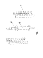
- FIG. 4 shows the linear actuator of the load-bearing assemblies
- FIG. 5 shows a clamp of one of the two load-bearing assembly parts
- FIG. 6 shows the clamp of the other load-bearing assembly
- FIG. 7 shows an actuator of a clamp
- FIG. 8 shows the bearing elements of a load-bearing assembly
- FIG. 9 shows a trolley that can be mounted on belts.
- FIG. 1 shows an overview of the possible application of a climbing robot according to the invention and a maintenance dock according to the invention attached thereto in a wind turbine with a mast or tower 1 on which the climbing robot can step, which is to say climb up or down discontinuously, for example in order to perform maintenance work on a rotor blade 2 .
- FIGS. 2 and 3 show the climbing robot 3 and the maintenance dock 4 in greater detail.
- the climbing robot 3 comprises a first load-bearing assembly 5 and a second load-bearing assembly 6 .
- the first load-bearing assembly 5 is subdivided into two load-bearing assembly parts 5 A and 5 B that are vertically spaced and connected by guide rails 7 on which the load-bearing assembly 6 can be moved up and down between the load-bearing assembly parts 5 A and 5 B by a linear actuator 8 .
- This linear actuator 8 is shown in greater detail in FIG. 4 and comprises a spindle 8 A that can be rotated by a motor attached at both ends of the load-bearing assembly 5 .
- the spindle bears a nut 8 B that is connected to the load-bearing assembly 6 .
- the load-bearing assembly 6 is guided in or on the vertical rails 7 that connect the two load-bearing assembly parts of the load-bearing assembly 5 between their confronting edges.
- the load-bearing assembly 5 comprises two clamps consisting of several components, with a clamp being arranged on the upper load-bearing assembly part 5 A and one being arranged on the lower load-bearing assembly part 5 B.
- the load-bearing assembly 6 also has two clamps.
- each clamp comprises a belt 9 .
- Each belt can—as shown in FIG. 1 —engage around the outer periphery of a mast 1 and bears against same at least in the gripping position.
- the ends of each belt 9 are guided through recesses and slide sleeves 10 therein into the interior of a load-bearing assembly 5 or 6 , and each end is wound onto or unwound from its own winding roller 11 .
- a respective deflecting roller 27 shifts the belt 9 lengthwise between each sliding sleeve 10 and winding roller 11 .
- the deflecting rollers are spaced more closely than the winding rollers.
- each belt can bear against the circumference of a mast 1 over an angle ⁇ >300° as shown in FIG. 3 . This results in an especially large load transmission surface.
- each of the load-bearing assemblies has bearing elements 12 shown in FIG. 8 and having surfaces 12 A that can bear radially inward against the surface of a mast or tower.
- Prism-shaped bodies 12 B form the grip faces 12 A and can be pressed from the load-bearing assembly 5 or 6 toward the mast or pulled away from it by an actuator.
- push rods 12 C can be used to which an actuator is coupled.
- the movement of the climbing robot occurs such that one of the load-bearing assemblies 5 or 6 on the mast or tower 1 is locked by gripping the bearing elements against the mast through winding-up of the respective belts 9 , as a result of which the cross-sectional area defined within the belt 9 is reduced, thus firmly enclosing a mast.
- the other load-bearing assembly is released by unwinding of the respective belt from the respective winding rollers 11 and retraction of the bearing elements 12 .
- the linear actuator 8 then moves the released load-bearing assembly linearly vertically up or down relative to the fixed load-bearing assembly.
- Linear actuators 13 that connect the belts 9 of different load-bearing assemblies are also extended or retracted synchronously to the width of motion of the load-bearing assemblies with respect to each other. As a result, the loose belts 9 are held against gravity in a horizontal position and moved along.
- the linear actuators 13 are preferably only arranged in the cross-sectional halves facing away from the load-bearing assemblies 5 or 6 .
- the moved load-bearing assembly is then clamped, and the previously clamped one is released and moved along in the same way.
- FIG. 7 shows one possible mechanism of an actuator of the winding rollers 11 .
- a motor 14 synchronously rotates two winding shafts 15 via a gear unit, or only one of the winding shafts 15 is coupled with the motor by a coupling 16 .
- the winding shafts can have a locking mechanism 15 A that only permits rotation one direction of rotation, namely that which brings about a clamping of a belt 9 .
- a locking element 15 B that blocks the reverse rotation of the shaft 15 is disengaged by an actuator (not shown here). In this way, it is ensured that an existing gripping position is not released in the event of a power outage.
- FIG. 9 shows a trolley 17 that is mounted in multiple, equal design on the belt 9 , distributed over the periphery of the mast. Part of the belt 9 passes through a slotted retaining sleeve 18 . and the sleeve 18 and the belt 9 are attached to a bridge element 19 via a tension spring 20 with the element 19 bridging vertically over the belt 9 and bearing at ends via rollers on the surface of the mast or tower when a load-bearing assembly is moved with the released belt 9 .
- the belt 9 When the belt 9 is released and the tension therein decreases, it is pulled off the mast surface by the tension spring 20 , so that the belt is moved further only by rolling. In contrast, if the tension is increased by winding up the belt with the winding rollers 11 , then the belt is pulled against the spring 20 onto the outer surface of the mast or tower and bears firmly against it with the spring 20 being maximally tensioned for the next retraction.
- the maintenance dock shown in FIGS. 2 and 3 comprises two dock shells 21 A and 21 B whose openings face each other.
- each dock shell is attached to two support beams 22 (here horizontal, for example) and can be moved in guide rails 23 in two mutually perpendicular directions.
- the support beams are fastened on the outer corners of the load-bearing assembly parts 5 A and 5 B.
- These load-bearing assemblies 5 A, 5 B, which are connected by guide rails 7 to a single load-bearing assembly 5 can thus form an assembly platform, for example, for the support beams of the maintenance dock that are shown here.
- the height of the shells can be adjusted here with the climbing robot, with the spacing from the mast and spacing of the shells 21 A and 21 B from each other or from a rotor blade 2 being possible by moving the shells 21 A and 21 B in the rails 23 .
- the shells 21 A and 21 B have vertically spaced cutouts 24 at the edges with which the cross section of a vertically hanging rotor blade can be enclosed when the shells are moved together.
- the remaining residual cross section can optionally be closed by inflating a bladder in the edges of the recesses 24 .
- Rails 25 are arranged inside the shells 21 A and 21 B with which a maintenance device 26 can be moved relative to the maintenance object, a rotor blade 2 in this case.
- a measuring element that detects the movement of the dock shells can be provided, and the actuators can be controlled on the basis of its signal.
Landscapes
- Engineering & Computer Science (AREA)
- Architecture (AREA)
- Mechanical Engineering (AREA)
- Combustion & Propulsion (AREA)
- Chemical & Material Sciences (AREA)
- Structural Engineering (AREA)
- Civil Engineering (AREA)
- Sustainable Development (AREA)
- Life Sciences & Earth Sciences (AREA)
- Sustainable Energy (AREA)
- General Engineering & Computer Science (AREA)
- Transportation (AREA)
- Wind Motors (AREA)
Applications Claiming Priority (4)
| Application Number | Priority Date | Filing Date | Title |
|---|---|---|---|
| DE102012001725A DE102012001725A1 (de) | 2012-01-31 | 2012-01-31 | Kletterroboter für Masten |
| DE102012001725 | 2012-01-31 | ||
| DE102012001725.1 | 2012-01-31 | ||
| PCT/EP2013/000270 WO2013113494A2 (de) | 2012-01-31 | 2013-01-30 | Kletterroboter für masten |
Publications (2)
| Publication Number | Publication Date |
|---|---|
| US20150090504A1 US20150090504A1 (en) | 2015-04-02 |
| US9327784B2 true US9327784B2 (en) | 2016-05-03 |
Family
ID=47740890
Family Applications (1)
| Application Number | Title | Priority Date | Filing Date |
|---|---|---|---|
| US14/374,944 Expired - Fee Related US9327784B2 (en) | 2012-01-31 | 2013-01-30 | Climbing robot for masts |
Country Status (5)
| Country | Link |
|---|---|
| US (1) | US9327784B2 (de) |
| EP (2) | EP2896823B1 (de) |
| DE (1) | DE102012001725A1 (de) |
| ES (1) | ES2672493T3 (de) |
| WO (1) | WO2013113494A2 (de) |
Cited By (8)
| Publication number | Priority date | Publication date | Assignee | Title |
|---|---|---|---|---|
| CN106948593A (zh) * | 2017-02-28 | 2017-07-14 | 深圳市特辰科技股份有限公司 | 一种轮式机器人爬架 |
| US20180009102A1 (en) * | 2016-07-08 | 2018-01-11 | ETAK Systems, LLC | Mechanical tower climber for operations on cell towers |
| US20180274332A1 (en) * | 2015-09-25 | 2018-09-27 | Subsea 7 Limited | Moving Tools on Offshore Structures with a Walking Carriage |
| CN109331431A (zh) * | 2018-09-21 | 2019-02-15 | 合肥尚伍信息科技有限公司 | 一种用于竖直杆稳定爬升运输的自动爬升装置 |
| CN109591906A (zh) * | 2019-01-28 | 2019-04-09 | 山东建筑大学 | 一种输电杆塔攀爬机器人控制系统及控制方法 |
| US20190134824A1 (en) * | 2017-09-21 | 2019-05-09 | Infrastructure Preservation Corporation | Robotic repair system for high mast light poles |
| US11117267B2 (en) | 2019-08-16 | 2021-09-14 | Google Llc | Robotic apparatus for operating on fixed frames |
| US11808250B2 (en) * | 2016-09-23 | 2023-11-07 | Leunamme Engineering S.L.U. | Method and equipment for replacing wind turbine components |
Families Citing this family (85)
| Publication number | Priority date | Publication date | Assignee | Title |
|---|---|---|---|---|
| CN103663309B (zh) * | 2013-11-12 | 2016-02-17 | 东莞市骏兴机械科技有限公司 | 卷型重物的电动伺服夹取移动系统 |
| CN103603774B (zh) * | 2013-11-18 | 2016-03-16 | 长春理工大学 | 一种风电自举升系统 |
| CN103692436B (zh) * | 2013-12-20 | 2016-05-04 | 马鞍山市力翔机械自动化科技有限公司 | 爬缆机器人 |
| CN103644084B (zh) * | 2013-12-23 | 2017-01-25 | 长春理工大学 | 一种分阶段举升方法 |
| ES2540790B1 (es) * | 2014-01-11 | 2016-04-20 | Cástor CASAS TOJO | Sistema de grúas autoescalables y autoajustables para aerogeneradores |
| US10384804B2 (en) * | 2015-04-14 | 2019-08-20 | ETAK Systems, LLC | Cell tower installation and maintenance systems and methods using robotic devices |
| CN105059415A (zh) * | 2015-08-06 | 2015-11-18 | 中国林业科学研究院林业新技术研究所 | 攀爬机器人 |
| CN105126316B (zh) * | 2015-09-20 | 2017-05-31 | 衢州妙凯节能科技有限公司 | 一种伸缩型管道攀爬机 |
| CN105253213A (zh) * | 2015-10-27 | 2016-01-20 | 昆明理工大学 | 一种爬杆机器人 |
| CN105345806B (zh) * | 2015-12-07 | 2017-10-27 | 中国石油大学(北京) | 自主升降监控机器人 |
| JP6154921B1 (ja) * | 2016-01-15 | 2017-06-28 | 日綜産業株式会社 | 風力発電装置におけるブレードのメンテナンス用ゴンドラ装置 |
| CN105947008B (zh) * | 2016-05-13 | 2018-02-16 | 陈奕冰 | 一种爬树机器人 |
| CN106112993B (zh) * | 2016-08-22 | 2018-02-06 | 常州信息职业技术学院 | 一种交替式爬杆机器人 |
| CN106347516B (zh) * | 2016-11-01 | 2024-03-26 | 新疆大学 | 一种气动爬杆机器人载物平台的设计 |
| CN108340364B (zh) * | 2017-01-24 | 2020-09-15 | 南京原觉信息科技有限公司 | 爬行机器装置与其部署方法 |
| CN107031747B (zh) * | 2017-03-28 | 2019-01-29 | 东南大学 | 一种变直径爬杆机器人 |
| WO2018184741A1 (en) * | 2017-04-05 | 2018-10-11 | Siemens Wind Power A/S | Parking assembly |
| WO2018204490A1 (en) * | 2017-05-02 | 2018-11-08 | Infrastructure Preservation Corporation | Robotic inspection system for high mast light poles |
| CN107472392B (zh) * | 2017-07-07 | 2023-04-07 | 武汉科技大学 | 一种轮式越障爬杆机器人 |
| CN107640242B (zh) * | 2017-09-21 | 2023-10-27 | 山东建筑大学 | 开合式结构的旋转载物平台和攀爬机器人 |
| CN107877426A (zh) * | 2017-12-14 | 2018-04-06 | 广东电网有限责任公司惠州供电局 | 一种杆塔倾斜监测专用传感器的夹具 |
| CN108252211B (zh) * | 2017-12-23 | 2024-03-26 | 香港中文大学(深圳) | 攀爬式检测机器人 |
| CN108644073B (zh) * | 2018-03-24 | 2020-03-13 | 北京工业大学 | 一种风力发电机塔筒的清洁机器人 |
| CN108516025A (zh) * | 2018-03-28 | 2018-09-11 | 李清花 | 一种自动爬杆装置 |
| CN109455241B (zh) * | 2018-04-09 | 2020-09-29 | 国家电网公司 | 一种转位爬杆机构 |
| CN108725621A (zh) * | 2018-06-14 | 2018-11-02 | 广东珺桦能源科技有限公司 | 一种砍树机器人用的攀爬机构 |
| CN108555940B (zh) * | 2018-07-04 | 2020-07-07 | 南京原觉信息科技有限公司 | 爬行机器人及其爬杆结构 |
| CN108749945B (zh) * | 2018-07-27 | 2023-10-20 | 贵州电网有限责任公司 | 一种多功能电杆爬杆机器人 |
| CN108891499B (zh) * | 2018-07-27 | 2023-10-20 | 贵州电网有限责任公司 | 一种用于电杆爬杆机器人的夹紧装置 |
| CN109484505A (zh) * | 2018-11-21 | 2019-03-19 | 杨聪智 | 爬升单元及爬升装置 |
| CN109895114B (zh) * | 2019-03-12 | 2024-02-27 | 广东机电职业技术学院 | 一种气动肌肉驱动的多边形结构的攀爬机器人 |
| CN109819798B (zh) * | 2019-03-15 | 2021-03-30 | 广西大学 | 一种利用自身重力增加爬升力的桉树修枝机 |
| CN110227241A (zh) * | 2019-04-28 | 2019-09-13 | 王清国 | 一种电力设施检修用电线杆攀爬工具 |
| CN110255430B (zh) * | 2019-06-20 | 2023-11-03 | 深圳市翠箓科技绿化工程有限公司 | 一种导轨攀爬机器人 |
| CN110254545B (zh) * | 2019-06-25 | 2024-07-23 | 北京史河科技有限公司 | 一种爬壁机器人 |
| CN112524401B (zh) * | 2019-08-29 | 2024-04-30 | 临颍县爬杆机器人有限公司 | 一种收紧式载物平台 |
| CN112441153A (zh) * | 2019-08-29 | 2021-03-05 | 临颍县爬杆机器人有限公司 | 一种爬杆机器人 |
| ES3014258T3 (en) * | 2019-09-05 | 2025-04-21 | Pp Energy Aps | Blade access arrangement for a rotor blade of a wind power plant |
| CN110952443B (zh) * | 2019-11-21 | 2024-07-02 | 深圳市人工智能与机器人研究院 | 一种分体式缆索攀爬检测机器人 |
| CN110757319A (zh) * | 2019-11-25 | 2020-02-07 | 沈阳工业大学 | 具备爬行功能的立柱油漆自动清理打磨机 |
| CN111113441B (zh) * | 2019-12-13 | 2023-02-03 | 国网浙江嘉善县供电有限公司 | 一种带电作业机器人移动装置 |
| CN110893977B (zh) * | 2019-12-16 | 2021-06-04 | 华能山东发电有限公司众泰电厂 | 一种发电设备安装用配件运输装置 |
| CN111173692A (zh) * | 2019-12-31 | 2020-05-19 | 上海扩博智能技术有限公司 | 用于风机叶片的检修工具挂载装置 |
| CN111232080B (zh) * | 2020-03-12 | 2021-01-12 | 国网安徽省电力有限公司电力科学研究院 | 一种环抱式爬杆机器人 |
| CN111330895B (zh) * | 2020-04-07 | 2024-08-02 | 机械科学研究总院海西(福建)分院有限公司 | 一种高速路反光板自动清洗装置 |
| CN111661189B (zh) * | 2020-06-10 | 2021-08-13 | 邯郸职业技术学院 | 管道爬行机器人 |
| CN111688837B (zh) * | 2020-06-19 | 2021-11-23 | 重庆大学 | 一种基于主动夹紧装置的高速攀爬机器人 |
| CN111957017A (zh) * | 2020-08-28 | 2020-11-20 | 陈克俊 | 一种安装横担自动爬杆装置 |
| CN111976858B (zh) * | 2020-08-31 | 2022-04-15 | 国家电网有限公司 | 一种电力抢险辅助攀高机器人 |
| CN112356940B (zh) * | 2020-10-13 | 2023-01-06 | 国网安徽省电力有限公司 | 一种角钢塔用攀爬机器人 |
| CN112278107B (zh) * | 2020-10-13 | 2025-04-04 | 国网安徽省电力有限公司 | 一种攀爬机器人用夹爪 |
| CN112290448B (zh) * | 2020-10-16 | 2021-12-03 | 重庆浪尖智能科技研究院有限公司 | 攀爬机器人的攀爬方法 |
| EP3995693A1 (de) | 2020-11-10 | 2022-05-11 | PP Energy ApS | Temporäre einhausung für mindestens einen teil einer rotorschaufel |
| CN112536798B (zh) * | 2020-12-01 | 2022-09-20 | 黑龙江大学 | 一种高压输电主塔架爬行机器人 |
| CN112722102A (zh) * | 2020-12-03 | 2021-04-30 | 中国电力科学研究院有限公司 | 一种用于输电线路铁塔塔身攀爬机器人的环抱式足部 |
| CN112828499B (zh) * | 2020-12-30 | 2023-03-14 | 北京博清科技有限公司 | 焊接装置、其控制方法、控制装置、处理器和焊接系统 |
| CN112855475B (zh) * | 2021-01-12 | 2021-11-26 | 哈尔滨理工大学 | 一种可自动更换风力发电机主轴轴承的装置 |
| CN113428252B (zh) * | 2021-08-17 | 2022-07-12 | 深圳市人工智能与机器人研究院 | 一种缆索攀爬机器人 |
| CN113685698B (zh) * | 2021-09-26 | 2022-10-11 | 七腾机器人有限公司 | 一种同步带管道爬行机器人及周向转动方法 |
| CN113877161B (zh) * | 2021-10-15 | 2024-09-17 | 国网江苏省电力有限公司东海县供电分公司 | 重力自锁式电线杆载重攀爬机器人 |
| EP4441362B1 (de) * | 2021-12-01 | 2025-08-13 | Aerones Engineering, SIA | Wartungsvorrichtung für windkraftanlage |
| CN114313045B (zh) * | 2021-12-23 | 2023-12-26 | 中国科学院宁波材料技术与工程研究所 | 爬杆机器人 |
| CN113984806B (zh) * | 2021-12-29 | 2022-03-08 | 山东东研智能科技有限公司 | 一种压力管道环向焊接接头射线检测辅助装置 |
| ES3017139T3 (en) | 2022-01-24 | 2025-05-12 | Pp Energy Aps | Wind turbine blade maintenance platform |
| CN114670946B (zh) * | 2022-04-11 | 2023-07-25 | 南京邮电大学 | 一种攀爬机器人用行走机构 |
| CN117087782A (zh) * | 2022-05-13 | 2023-11-21 | 香港物流机械人研究中心有限公司 | 一种基于链式传动的爬杆机器人 |
| NL2032171B1 (en) * | 2022-06-15 | 2023-12-21 | Ampelmann Holding B V | A support structure, a wind turbine blade, a wind turbine and a method |
| CN115180038B (zh) * | 2022-06-24 | 2023-08-22 | 永康市光明送变电工程有限公司 | 一种用机器人攀爬避雷针的方式 |
| CN115234761A (zh) * | 2022-06-27 | 2022-10-25 | 河南高建工程管理有限公司 | 一种桥梁结构病害检测装置及其检测方法 |
| CN114803966B (zh) * | 2022-06-30 | 2022-11-11 | 山西省安装集团股份有限公司 | 一种用于风力发电机的塔筒攀爬装置 |
| CN115324848B (zh) * | 2022-08-23 | 2025-07-22 | 华能广西清洁能源有限公司 | 一种皮带式风力发电机塔筒外壁清洗装置 |
| CN115817518B (zh) * | 2022-12-15 | 2023-07-14 | 天津大学 | 一种用于风电塔筒爬行装置的多维安全控制装置及方法 |
| CN116692731B (zh) * | 2023-02-14 | 2026-03-03 | 杭州夸克电力科技有限公司 | 一种柱上断路器用多功能检测设备及检测方法 |
| CN116135691B (zh) * | 2023-04-18 | 2023-06-30 | 广东智能无人系统研究院(南沙) | 一种双模式水下结构清理检测机器人 |
| CN116424451A (zh) * | 2023-04-20 | 2023-07-14 | 河海大学 | 一种爬杆检测机器人 |
| CN116972275B (zh) * | 2023-07-14 | 2026-03-03 | 哈尔滨工业大学 | 一种带有强开功能的平行开合越障的磁传感器驱动装置 |
| CN116876339B (zh) * | 2023-07-31 | 2025-11-25 | 安徽省公路桥梁工程有限公司 | 城市轨道交通工程桥梁支座检修装置及其施工工艺 |
| CN121866403A (zh) * | 2023-09-20 | 2026-04-14 | 维斯塔斯风力系统有限公司 | 使用风力涡轮机转子或叶片维护工具的方法以及用于该方法的转子或叶片工具 |
| CN117404528B (zh) * | 2023-12-14 | 2024-03-29 | 临汾淼森能源工程有限公司 | 一种供热工程施工用管道固定装置 |
| CN118208031B (zh) * | 2024-05-21 | 2024-08-09 | 融亿建工集团有限公司 | 一种烟囱彩绘吊篮的安装装置 |
| CN119042088A (zh) * | 2024-08-13 | 2024-11-29 | 南通理工学院 | 用于风电发电机的变径塔筒爬升的环抱束缚系统 |
| CN119459914B (zh) * | 2024-10-09 | 2025-09-26 | 国网河南省电力公司商丘供电公司 | 一种电网爬杆作业机器人 |
| CN119636939B (zh) * | 2024-12-12 | 2025-10-28 | 重庆邮电大学 | 一种可伸缩柔性体攀爬装置 |
| CN120099874A (zh) * | 2025-05-08 | 2025-06-06 | 交通运输部公路科学研究所 | 一种变径墩柱攀爬机器人及工作方法 |
| CN120922264B (zh) * | 2025-10-14 | 2026-02-10 | 山东元开电气有限公司 | 一种智能电杆攀爬喷涂作业机器人及方法 |
Citations (13)
| Publication number | Priority date | Publication date | Assignee | Title |
|---|---|---|---|---|
| US350289A (en) | 1886-10-05 | Thirds to thomas andrew porter | ||
| US2906365A (en) | 1957-01-11 | 1959-09-29 | Arthur R Howard | Automatic scaffolding machine |
| US3586127A (en) | 1968-02-03 | 1971-06-22 | Robert H Jones | Stack-climbing systems |
| US4893512A (en) * | 1987-06-12 | 1990-01-16 | Doryokuro Kakunenryo Kaihatsu Jigyodan | Swinging-type automatic examination apparatus for piping |
| DE19909698A1 (de) | 1998-09-22 | 2000-04-13 | Siebert Antonius J | Vorrichtung zur Durchführung von Reparatur- und Serviceleistungen insbesondere an Rotorblättern von Windkraftanlagen |
| DE102005016931B3 (de) | 2004-12-17 | 2006-05-11 | Carsten Paulsen | Reinigungsanlage für Türme von Windkraftanlagen |
| DE102005053782A1 (de) | 2004-11-09 | 2006-06-22 | Ebf Dresden Gmbh Forschung, Entwicklung, Erprobung | Selbstkletternde Vorrichtung |
| US20110031066A1 (en) | 2009-08-04 | 2011-02-10 | General Electric Company | Tower climbing and servicing device |
| US20110100734A1 (en) * | 2008-03-28 | 2011-05-05 | Thales | Robot for Climbing Posts |
| US20120103705A1 (en) * | 2010-09-30 | 2012-05-03 | Schlee Keith L | Multi-unit mobile robot |
| US8201787B2 (en) | 2005-01-19 | 2012-06-19 | Iti Scotland Limited | Clamp, self-advancing climbing device, and method of coupling same to a tubular |
| US20130140801A1 (en) * | 2011-12-02 | 2013-06-06 | Helical Robotics, Llc | Mobile robot |
| US8944192B2 (en) * | 2010-04-20 | 2015-02-03 | Savannah River Nuclear Solutions, Llc | Robotic platform for traveling on vertical piping network |
Family Cites Families (4)
| Publication number | Priority date | Publication date | Assignee | Title |
|---|---|---|---|---|
| DE29819391U1 (de) * | 1998-09-22 | 1999-02-11 | Robl, Klaus A., 59505 Bad Sassendorf | Vorrichtung zur Durchführung von Reparatur- und Serviceleistungen insbesondere an Rotorblättern von Windkraftanlagen |
| DE10118906B4 (de) * | 2001-05-25 | 2009-04-09 | Müller, Holger | Vorrichtung und Verfahren für die Beschichtung von Rotorblättern von Windkraftanlagen |
| DE102010011365B4 (de) * | 2010-03-12 | 2016-01-21 | Andre Dochow | Wetterschutz für Arbeitsbühnen an Propellerblättern von Windkraftanlagen |
| US8641374B2 (en) * | 2010-06-30 | 2014-02-04 | Vestas Wind Systems A/S | Cleaning and inspecting apparatus for wind turbine and related methods |
-
2012
- 2012-01-31 DE DE102012001725A patent/DE102012001725A1/de not_active Withdrawn
-
2013
- 2013-01-30 EP EP15000598.1A patent/EP2896823B1/de not_active Not-in-force
- 2013-01-30 ES ES13705098.5T patent/ES2672493T3/es active Active
- 2013-01-30 EP EP13705098.5A patent/EP2809946B1/de not_active Not-in-force
- 2013-01-30 WO PCT/EP2013/000270 patent/WO2013113494A2/de not_active Ceased
- 2013-01-30 US US14/374,944 patent/US9327784B2/en not_active Expired - Fee Related
Patent Citations (13)
| Publication number | Priority date | Publication date | Assignee | Title |
|---|---|---|---|---|
| US350289A (en) | 1886-10-05 | Thirds to thomas andrew porter | ||
| US2906365A (en) | 1957-01-11 | 1959-09-29 | Arthur R Howard | Automatic scaffolding machine |
| US3586127A (en) | 1968-02-03 | 1971-06-22 | Robert H Jones | Stack-climbing systems |
| US4893512A (en) * | 1987-06-12 | 1990-01-16 | Doryokuro Kakunenryo Kaihatsu Jigyodan | Swinging-type automatic examination apparatus for piping |
| DE19909698A1 (de) | 1998-09-22 | 2000-04-13 | Siebert Antonius J | Vorrichtung zur Durchführung von Reparatur- und Serviceleistungen insbesondere an Rotorblättern von Windkraftanlagen |
| DE102005053782A1 (de) | 2004-11-09 | 2006-06-22 | Ebf Dresden Gmbh Forschung, Entwicklung, Erprobung | Selbstkletternde Vorrichtung |
| DE102005016931B3 (de) | 2004-12-17 | 2006-05-11 | Carsten Paulsen | Reinigungsanlage für Türme von Windkraftanlagen |
| US8201787B2 (en) | 2005-01-19 | 2012-06-19 | Iti Scotland Limited | Clamp, self-advancing climbing device, and method of coupling same to a tubular |
| US20110100734A1 (en) * | 2008-03-28 | 2011-05-05 | Thales | Robot for Climbing Posts |
| US20110031066A1 (en) | 2009-08-04 | 2011-02-10 | General Electric Company | Tower climbing and servicing device |
| US8944192B2 (en) * | 2010-04-20 | 2015-02-03 | Savannah River Nuclear Solutions, Llc | Robotic platform for traveling on vertical piping network |
| US20120103705A1 (en) * | 2010-09-30 | 2012-05-03 | Schlee Keith L | Multi-unit mobile robot |
| US20130140801A1 (en) * | 2011-12-02 | 2013-06-06 | Helical Robotics, Llc | Mobile robot |
Cited By (14)
| Publication number | Priority date | Publication date | Assignee | Title |
|---|---|---|---|---|
| US20180274332A1 (en) * | 2015-09-25 | 2018-09-27 | Subsea 7 Limited | Moving Tools on Offshore Structures with a Walking Carriage |
| US10590745B2 (en) * | 2015-09-25 | 2020-03-17 | Subsea 7 Limited | Moving tools on offshore structures with a walking carriage |
| US20180009102A1 (en) * | 2016-07-08 | 2018-01-11 | ETAK Systems, LLC | Mechanical tower climber for operations on cell towers |
| US10456906B2 (en) * | 2016-07-08 | 2019-10-29 | ETAK Systems, LLC | Mechanical tower climber for operations on cell towers |
| US11808250B2 (en) * | 2016-09-23 | 2023-11-07 | Leunamme Engineering S.L.U. | Method and equipment for replacing wind turbine components |
| CN106948593B (zh) * | 2017-02-28 | 2019-12-27 | 深圳市特辰科技股份有限公司 | 一种轮式机器人爬架 |
| CN106948593A (zh) * | 2017-02-28 | 2017-07-14 | 深圳市特辰科技股份有限公司 | 一种轮式机器人爬架 |
| US10919590B2 (en) * | 2017-09-21 | 2021-02-16 | Infrastructure Preservation Corporation | Robotic repair system for high mast light poles |
| US20190134824A1 (en) * | 2017-09-21 | 2019-05-09 | Infrastructure Preservation Corporation | Robotic repair system for high mast light poles |
| CN109331431A (zh) * | 2018-09-21 | 2019-02-15 | 合肥尚伍信息科技有限公司 | 一种用于竖直杆稳定爬升运输的自动爬升装置 |
| CN109591906A (zh) * | 2019-01-28 | 2019-04-09 | 山东建筑大学 | 一种输电杆塔攀爬机器人控制系统及控制方法 |
| US11117267B2 (en) | 2019-08-16 | 2021-09-14 | Google Llc | Robotic apparatus for operating on fixed frames |
| US11745358B2 (en) | 2019-08-16 | 2023-09-05 | Google Llc | Robotic apparatus for operating on fixed frames |
| US12005571B2 (en) | 2019-08-16 | 2024-06-11 | Google Llc | Robotic apparatus for operating on fixed frames |
Also Published As
| Publication number | Publication date |
|---|---|
| WO2013113494A2 (de) | 2013-08-08 |
| WO2013113494A3 (de) | 2013-10-03 |
| EP2809946A2 (de) | 2014-12-10 |
| ES2672493T3 (es) | 2018-06-14 |
| EP2809946B1 (de) | 2018-03-07 |
| EP2896823B1 (de) | 2018-05-16 |
| DE102012001725A1 (de) | 2013-08-01 |
| US20150090504A1 (en) | 2015-04-02 |
| EP2896823A1 (de) | 2015-07-22 |
Similar Documents
| Publication | Publication Date | Title |
|---|---|---|
| US9327784B2 (en) | Climbing robot for masts | |
| DE102013002886B3 (de) | Vorrichtung zur Befahrung von Türmen und/oder turmartigen Bauwerken, insbesondere von Windkraftanlagen | |
| US9809308B2 (en) | Load transport and restraining devices and methods for restraining loads | |
| US9022332B2 (en) | Clamping system and self advancing support platform | |
| US10494235B2 (en) | Crane system and an associated method thereof | |
| US9260875B2 (en) | Support arrangement of a wind turbine tower | |
| US20170234165A1 (en) | Gas turbine engine package and corresponding method | |
| KR101487311B1 (ko) | 관체 외주면 도장유닛 | |
| EP3299615B1 (de) | System zur montage/demontage von schaufeln in windturbinen | |
| EP2771160B1 (de) | Vorrichtung und verfahren zur herstellung von länglichen produkten wie z. b. windturbinenschaufeln | |
| CN116544845A (zh) | 一种导线间隔棒自动安装机器人 | |
| WO2015090282A1 (de) | Halte-, hebe- und sicherungsvorrichtung zur anbringung an hohen, turmartigen bauwerken | |
| KR20170103683A (ko) | 기어 시스템의 수축 요소를 핸들링하기 위한 호이스트 툴 | |
| US9188007B2 (en) | Gas turbine shaft bearing system service tool and bearing system service method | |
| US10982459B2 (en) | Rotating a long vessel | |
| WO2015003694A1 (de) | Vorrichtung zur inspektion einer windkraftanlage | |
| CN118208628B (zh) | 一种可变直径的复合管道外缺陷环形修补装置 | |
| CN215848291U (zh) | 伸缩工作手臂 | |
| CN205169938U (zh) | 塑料薄膜收卷系统 | |
| US20180186102A1 (en) | A pipe forming assembly and method of use | |
| CN116553443A (zh) | 高空作业装置 | |
| WO2018215088A1 (de) | Befahranlage zum befahren der oberflächen von masten oder rohren | |
| WO2005005822A1 (en) | Apparatus and method for clamping friction surfaces to a tubular structure | |
| CN121134503A (zh) | 一种用于风电机组运维的吊装设备 | |
| CN223225576U (zh) | 一种收放卷胀轴装置 |
Legal Events
| Date | Code | Title | Description |
|---|---|---|---|
| AS | Assignment |
Owner name: FACHHOCHSCHULE AACHEN, GERMANY Free format text: ASSIGNMENT OF ASSIGNORS INTEREST;ASSIGNORS:BAGHERI, MOHSEN;DAHMANN, PETER;REEL/FRAME:033599/0288 Effective date: 20140821 |
|
| STCF | Information on status: patent grant |
Free format text: PATENTED CASE |
|
| MAFP | Maintenance fee payment |
Free format text: PAYMENT OF MAINTENANCE FEE, 4TH YR, SMALL ENTITY (ORIGINAL EVENT CODE: M2551); ENTITY STATUS OF PATENT OWNER: SMALL ENTITY Year of fee payment: 4 |
|
| FEPP | Fee payment procedure |
Free format text: ENTITY STATUS SET TO SMALL (ORIGINAL EVENT CODE: SMAL); ENTITY STATUS OF PATENT OWNER: SMALL ENTITY |
|
| FEPP | Fee payment procedure |
Free format text: MAINTENANCE FEE REMINDER MAILED (ORIGINAL EVENT CODE: REM.); ENTITY STATUS OF PATENT OWNER: SMALL ENTITY |
|
| LAPS | Lapse for failure to pay maintenance fees |
Free format text: PATENT EXPIRED FOR FAILURE TO PAY MAINTENANCE FEES (ORIGINAL EVENT CODE: EXP.); ENTITY STATUS OF PATENT OWNER: SMALL ENTITY |
|
| STCH | Information on status: patent discontinuation |
Free format text: PATENT EXPIRED DUE TO NONPAYMENT OF MAINTENANCE FEES UNDER 37 CFR 1.362 |
|
| FP | Lapsed due to failure to pay maintenance fee |
Effective date: 20240503 |