EP2810091B1 - Dispositif de compensation d'interférences électromagnétiques pendant des mesures biomagnétiques - Google Patents
Dispositif de compensation d'interférences électromagnétiques pendant des mesures biomagnétiques Download PDFInfo
- Publication number
- EP2810091B1 EP2810091B1 EP12867179.9A EP12867179A EP2810091B1 EP 2810091 B1 EP2810091 B1 EP 2810091B1 EP 12867179 A EP12867179 A EP 12867179A EP 2810091 B1 EP2810091 B1 EP 2810091B1
- Authority
- EP
- European Patent Office
- Prior art keywords
- compensation elements
- compensation
- measuring device
- electromagnetic interferences
- biomagnetic
- Prior art date
- Legal status (The legal status is an assumption and is not a legal conclusion. Google has not performed a legal analysis and makes no representation as to the accuracy of the status listed.)
- Not-in-force
Links
- 238000005259 measurement Methods 0.000 title claims description 14
- 208000032365 Electromagnetic interference Diseases 0.000 title claims description 7
- 230000005291 magnetic effect Effects 0.000 claims description 27
- 239000007788 liquid Substances 0.000 claims description 6
- 230000008878 coupling Effects 0.000 claims description 5
- 238000010168 coupling process Methods 0.000 claims description 5
- 238000005859 coupling reaction Methods 0.000 claims description 5
- 239000002887 superconductor Substances 0.000 claims description 4
- 238000006073 displacement reaction Methods 0.000 claims description 3
- 230000001939 inductive effect Effects 0.000 claims description 3
- 239000004020 conductor Substances 0.000 claims description 2
- 238000000034 method Methods 0.000 description 8
- 230000009467 reduction Effects 0.000 description 7
- IJGRMHOSHXDMSA-UHFFFAOYSA-N Atomic nitrogen Chemical compound N#N IJGRMHOSHXDMSA-UHFFFAOYSA-N 0.000 description 6
- 241000238366 Cephalopoda Species 0.000 description 6
- 238000001816 cooling Methods 0.000 description 6
- 230000008901 benefit Effects 0.000 description 5
- 230000005294 ferromagnetic effect Effects 0.000 description 4
- 230000006698 induction Effects 0.000 description 4
- 239000000463 material Substances 0.000 description 4
- 238000005086 pumping Methods 0.000 description 4
- 239000000126 substance Substances 0.000 description 4
- 230000001965 increasing effect Effects 0.000 description 3
- 238000004519 manufacturing process Methods 0.000 description 3
- 230000007246 mechanism Effects 0.000 description 3
- 229910052757 nitrogen Inorganic materials 0.000 description 3
- 230000003287 optical effect Effects 0.000 description 3
- 230000001629 suppression Effects 0.000 description 3
- 230000003313 weakening effect Effects 0.000 description 3
- RYGMFSIKBFXOCR-UHFFFAOYSA-N Copper Chemical compound [Cu] RYGMFSIKBFXOCR-UHFFFAOYSA-N 0.000 description 2
- 230000001447 compensatory effect Effects 0.000 description 2
- 229910052802 copper Inorganic materials 0.000 description 2
- 239000010949 copper Substances 0.000 description 2
- 238000013461 design Methods 0.000 description 2
- 238000005516 engineering process Methods 0.000 description 2
- 238000011160 research Methods 0.000 description 2
- 230000035945 sensitivity Effects 0.000 description 2
- 229920002430 Fibre-reinforced plastic Polymers 0.000 description 1
- 102100026450 POU domain, class 3, transcription factor 4 Human genes 0.000 description 1
- 101710133389 POU domain, class 3, transcription factor 4 Proteins 0.000 description 1
- 206010041235 Snoring Diseases 0.000 description 1
- 229910052782 aluminium Inorganic materials 0.000 description 1
- XAGFODPZIPBFFR-UHFFFAOYSA-N aluminium Chemical compound [Al] XAGFODPZIPBFFR-UHFFFAOYSA-N 0.000 description 1
- 230000003321 amplification Effects 0.000 description 1
- 230000002238 attenuated effect Effects 0.000 description 1
- 230000008859 change Effects 0.000 description 1
- 238000013016 damping Methods 0.000 description 1
- 230000007547 defect Effects 0.000 description 1
- 230000001419 dependent effect Effects 0.000 description 1
- 239000003989 dielectric material Substances 0.000 description 1
- 230000000694 effects Effects 0.000 description 1
- 230000005672 electromagnetic field Effects 0.000 description 1
- 230000005674 electromagnetic induction Effects 0.000 description 1
- JBKVHLHDHHXQEQ-UHFFFAOYSA-N epsilon-caprolactam Chemical compound O=C1CCCCCN1 JBKVHLHDHHXQEQ-UHFFFAOYSA-N 0.000 description 1
- 239000011151 fibre-reinforced plastic Substances 0.000 description 1
- 239000011152 fibreglass Substances 0.000 description 1
- 239000001307 helium Substances 0.000 description 1
- 229910052734 helium Inorganic materials 0.000 description 1
- SWQJXJOGLNCZEY-UHFFFAOYSA-N helium atom Chemical compound [He] SWQJXJOGLNCZEY-UHFFFAOYSA-N 0.000 description 1
- 230000002452 interceptive effect Effects 0.000 description 1
- 238000011835 investigation Methods 0.000 description 1
- 238000005404 magnetometry Methods 0.000 description 1
- 229910052751 metal Inorganic materials 0.000 description 1
- 239000002184 metal Substances 0.000 description 1
- 238000010295 mobile communication Methods 0.000 description 1
- 229910052758 niobium Inorganic materials 0.000 description 1
- 239000010955 niobium Substances 0.000 description 1
- GUCVJGMIXFAOAE-UHFFFAOYSA-N niobium atom Chemical compound [Nb] GUCVJGMIXFAOAE-UHFFFAOYSA-N 0.000 description 1
- 238000003199 nucleic acid amplification method Methods 0.000 description 1
- 230000035515 penetration Effects 0.000 description 1
- 230000008569 process Effects 0.000 description 1
- 230000001681 protective effect Effects 0.000 description 1
- 239000003507 refrigerant Substances 0.000 description 1
- 230000001105 regulatory effect Effects 0.000 description 1
- 238000001228 spectrum Methods 0.000 description 1
- 230000036962 time dependent Effects 0.000 description 1
- 230000007704 transition Effects 0.000 description 1
Images

Classifications
-
- G—PHYSICS
- G01—MEASURING; TESTING
- G01N—INVESTIGATING OR ANALYSING MATERIALS BY DETERMINING THEIR CHEMICAL OR PHYSICAL PROPERTIES
- G01N27/00—Investigating or analysing materials by the use of electric, electrochemical, or magnetic means
- G01N27/72—Investigating or analysing materials by the use of electric, electrochemical, or magnetic means by investigating magnetic variables
-
- G—PHYSICS
- G01—MEASURING; TESTING
- G01R—MEASURING ELECTRIC VARIABLES; MEASURING MAGNETIC VARIABLES
- G01R1/00—Details of instruments or arrangements of the types included in groups G01R5/00 - G01R13/00 and G01R31/00
- G01R1/02—General constructional details
- G01R1/18—Screening arrangements against electric or magnetic fields, e.g. against earth's field
-
- G—PHYSICS
- G01—MEASURING; TESTING
- G01R—MEASURING ELECTRIC VARIABLES; MEASURING MAGNETIC VARIABLES
- G01R33/00—Arrangements or instruments for measuring magnetic variables
- G01R33/007—Environmental aspects, e.g. temperature variations, radiation, stray fields
- G01R33/0076—Protection, e.g. with housings against stray fields
-
- G—PHYSICS
- G01—MEASURING; TESTING
- G01R—MEASURING ELECTRIC VARIABLES; MEASURING MAGNETIC VARIABLES
- G01R33/00—Arrangements or instruments for measuring magnetic variables
- G01R33/02—Measuring direction or magnitude of magnetic fields or magnetic flux
- G01R33/025—Compensating stray fields
-
- G—PHYSICS
- G01—MEASURING; TESTING
- G01R—MEASURING ELECTRIC VARIABLES; MEASURING MAGNETIC VARIABLES
- G01R33/00—Arrangements or instruments for measuring magnetic variables
- G01R33/12—Measuring magnetic properties of articles or specimens of solids or fluids
- G01R33/1269—Measuring magnetic properties of articles or specimens of solids or fluids of molecules labeled with magnetic beads
Definitions
- the invention relates to the technical field of protection of high-sensitive measuring equipment against external interferences and could be used for protection against electromagnetic noises of systems, like magnetocardiographic complexes operated at unshielded premises.
- magnetometers such as superconductive quantum interference detectors (SQUIDs), optically pumping magnetometers or magnetoresistive sensors.
- SQUIDs superconductive quantum interference detectors
- magnetometers are characterized by high magnetic field resolution in the range of pico-femto Tesla.
- useful magnetic signal spectrum of biological objects for example, of the human heart
- the interference level under which normal performance of magnetometers is still survived, typically should not exceed 0.1 nT.
- ENSS includes several magnetometers with rather low sensitivity (reference channels) with separate electronics, placed among gradiometer (signal) channels.
- Reference channels use magnetometers with lower sensitivity than ones in signal channels.
- reference channels record MF of interferences in 3 orthogonal projections and form a reference vector magnetometer (RVM).
- RVM reference vector magnetometer
- Output signals of RVM are inverted, scaled and mixed with outputs of signal channels. For example, if interference X-signal at the RVM output is higher (lower) than the interference X-signal at the output of signal channel, RVM signal is amplified (attenuated) and subtracted from the signal at the output of signal channel.
- FR 2 512 965 A1 discloses compensation apparatus for balancing a second-order gradiometer for performing biomagnetic measurements.
- the second-order gradiometer comprises three coils and the compensation apparatus comprises a support for the coils that is subdivided into two elements. Means are provided for allowing the two elements to be moved by a small distance relative to each other.
- US 2004/106863 A1 discloses a magnetic shield having a cylindrical ferromagnetic substance having openings on both ends and two superconducting loops housed in the respective insides of superconducting loop containers.
- the superconducting loops are constructed of high T c superconducting wire.
- the two superconducting loops have semicircle shapes and are arranged in the x-direction so as to be symmetrical with respect to an axis of the cylindrical ferromagnetic substance.
- the superconducting loop containers are arranged in the insides near both open ends of the cylindrical ferromagnetic substance with supports.
- the superconducting loops are arranged to be vertical to the axis of the cylindrical ferromagnetic substance.
- the superconducting loops are cooled by liquid nitrogen or a refrigerator.
- TRALSHAWALA N ET AL "Reduction of ambient magnetic field noise for high-Tc SQUID applications", IEEE TRANSACTIONS ON APPLIED SUPERCONDUCTIVITY, IEEE SERVICE CENTER, LOS ALAMITOS, CA, US, vol. 7, no. 2, 1 June 1997, pages 2890-2893, XP011501061, ISSN: 1051-8223, DOI: 10.1109/77.621897 discloses the result of investigations on ambience noise reduction using localised high T c passive magnetic shields.
- WORDENWEBER R ET AL "Reduction of low-frequency noise in high-Tc SQUIDs by artificial defects"
- PHYSICA C NORTH-HOLLAND PUBLISHING
- AMSTERDAM AMSTERDAM
- disclosed devices instead of using reference magnetometers to register interference MF in three orthogonal directions X, Y, Z, disclosed devices use at least three rings of conductive materials (including superconductors), which are also orthogonally and close to the input antenna of biomagnetic metering device.
- Invention is based on the task of improving design of the device for passive compensation of electromagnetic interferences in measurement of biomagnetic signals at a high level of external electromagnetic interference and lack of magnetic and/or electromagnetic shielding or active noise compensation, in order of its simplification and cheapening, implementation of regulated compensation for, electromagnetic interference without necessity of device cooling to cryogenic temperatures, as well as using other types of biomagnetic metering devices instead of superconducting SQUID-magnetometers.
- the principle of passive compensation is following: electromagnetic or variable magnetic interference due to the phenomenon of electromagnetic induction generates eddy currents in the compensation element. These currents generate MF around this element, with direction opposite to the interference MF direction. Compensatory MF, which is the MFs vector sum of all 3 elements, enters the metering input, where it is added to the MF of interference. Amplitude and direction of the total compensation MP vector varies depending on position of the compensation elements relative to the metering device.
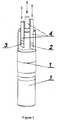
- Fig.1 Relative position scheme of 3 short-circuited rings and measuring device for biomagnetic fields is shown in Fig.1 , which illustrates the principle of the invention.
- Compensation rings 1-3 are arranged in 3 mutually orthogonal planes, which make it possible to compensate magnetic interference independently of its direction. All rings are located directly near the metering device 5 in order to provide penetration of induced MF almost without weakening inside the metering device or inside its sensor or input antenna, if any.
- compensation procedure elements are alternatively shifted up and down to control the level of interference on the meter output in absence of valid signal.
- compensation field becomes approximately equal in amplitude and opposite in direction to the MF of interference.
- the amplitude of interference MF at the measuring device input and signal amplitude at its output would reach a minimum.
- the basic implementation device also includes a separate mechanisms 4 (see. Fig. 1 ) for independent movement of each compensation ring relative to the metering device.
- the mechanisms consist of fastening elements, up and down shift elements and elements for fixing of the compensation rings in positions that provide minimum MF amplitude of the interference at the metering input. Parts of the mechanism provide frequent adjustment and fixing of rings according to changes of noise conditions in the measuring area.
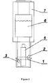
- cryostat 7 for biomagnetic measuring device is made permeable to low-frequency MF - magneto-transparent therefore manufactured of dielectrics, such as non-magnetic fiberglass.
- compensation rings 1-3 are fixed at cryostat surface or close to it, ensuring their temperature equal to ambient temperature, i.e. room temperature. According to the invention all compensation rings have only inductive coupling with the metering antenna when under the influence of induced currents MF enters the metering device, which compensates the interference MF.
- Fig.3 represents the version with cryogenic meter, for example, SQUID magnetometer, 5 , and all rings 1-3 are placed inside the cryostat near the input metering antenna 8 .
- Advantage of this option is possibility to increase current in the rings due to a decrease in their resistance by cooling, and to increase the amplitude of compensatory MF by reducing distance to the metering antenna.
- Drawback it's much harder to implement moving and fixing of rings inside the cryostat.
- At least one compensation element is manufactured of superconductive materials. Then the resistance of the ring may decrease to zero if the temperature inside the cryostat is lower than the superconductor's transition temperature to the superconductive state.
- Advantage of this option no damping of induced currents with frequency increasing, which allows compensation for a wide frequency range. Limitation of this implementation - it makes sense only for cryogenic metering device, placed in a cryostat.
- At least one additional compensation element that is placed in space so that it matches a particular spatial component of the field gradient.
- Number of additional elements depends on the number of said components, which are registered by the metering device, or the number of interference gradient components that should be compensated.
- device is used to compensate interference MF at the input of multi-channel meter. Thereat optimum position of the compensation elements is determined by the minimum amplitude of interference MF in several or the most of channels, by minimum of average amplitude of the interference MF in all channels, or in other way. But the principal difference of proposed device is that it is common to all channels, unlike of other such systems, for example ENSS systems, manufactured separately for each channel.
- the device compensation is combined with another noise reduction methods, for example, with ENSS, electromagnetic shielding or with any other means.
- ENSS e.g., ENSS
- electromagnetic shielding e.g., electromagnetic shielding
- any other means e.g., electromagnetic shielding, electromagnetic shielding or with any other means.
- Proposed device is industrially applicable and could be easily manufactured, because it is made of industrially developed materials (copper, niobium or other metal wire, kaprolon, textolite, various fiber-reinforced plastics) and based on standard technological processes. Its application field - ultrasensitive biomagnetometry, including magnetocardiography, susceptometry or other branch, scientific biomedical research, low-temperature physics and technology.
Landscapes
- Physics & Mathematics (AREA)
- General Physics & Mathematics (AREA)
- Condensed Matter Physics & Semiconductors (AREA)
- Health & Medical Sciences (AREA)
- Chemical & Material Sciences (AREA)
- Toxicology (AREA)
- Environmental & Geological Engineering (AREA)
- Spectroscopy & Molecular Physics (AREA)
- Engineering & Computer Science (AREA)
- Life Sciences & Earth Sciences (AREA)
- Electrochemistry (AREA)
- Chemical Kinetics & Catalysis (AREA)
- Analytical Chemistry (AREA)
- Biochemistry (AREA)
- General Health & Medical Sciences (AREA)
- Immunology (AREA)
- Pathology (AREA)
- Measuring Magnetic Variables (AREA)
- Measurement And Recording Of Electrical Phenomena And Electrical Characteristics Of The Living Body (AREA)
Claims (5)
- Dispositif de compensation d'interférences électromagnétiques pendant des mesures biomagnétiques à un niveau élevé d'interférences électromagnétiques externes, comprenant :un dispositif de mesure (5) de signaux biomagnétiques, etun moyen de compensation desdites interférences électromagnétiques, caractérisé en ce que :le dispositif de mesure (5) est conçu pour enregistrer trois composantes des signaux biomagnétiques, comprenant trois projections du vecteur champ magnétique et/ou son gradient spatial de premier ordre ou d'ordre supérieur,le dispositif de compensation d'interférences électromagnétiques comprend au moins trois éléments de compensation (1 à 3) et un moyen permettant de déplacer (4) les éléments de compensation (1 à 3),les éléments de compensation (1 à 3) comprennent chacun un contour court-circuité de forme arbitraire et sont fabriqués de matériaux électriquement conducteurs,les éléments de compensation (1 à 3) sont conçus de manière qu'ils ne présentent qu'un couplage inductif avec le dispositif de mesure (5) et pas de couplage galvanique,les éléments de compensation (1 à 3) comprennent trois éléments de compensation (1 à 3) placés autour du dispositif de mesure (5) dans l'espace, de manière que chaque projection du champ magnétique ou du gradient de champ satisfait au moins un élément,les moyens de déplacement (4) comprennent un moyen de décalage permettant de décaler, un moyen de maintien permettant de maintenir et un moyen de fixation permettant la fixation d'éléments de compensation (1 à 3),les moyens de déplacement (4) sont conçus pour effectuer un déplacement répété et une fixation des éléments de compensation (1 à 3) pour changer des conditions d'interférence à l'emplacement du dispositif de mesure (5),lesdits moyens de décalage, maintien et fixation sont mis en oeuvre pour un mouvement indépendant d'éléments de compensation individuels (1 à 3), etlesdits moyens de fixation sont conçus pour permettre la fixation des éléments de compensation (1 à 3) dans des positions avec une amplitude minimale d'interférences électromagnétiques lors d'une entrée du dispositif de mesure (5).
- Dispositif selon la revendication 1, caractérisé en ce que :le dispositif de mesure (4) est positionné à l'intérieur d'un refroidisseur et refroidi à l'aide de liquides cryogéniques ou d'un quelconque autre moyen, etles éléments de compensation (1 à 3) et les moyens de déplacement (4) sont placés à l'extérieur du refroidisseur.
- Dispositif selon la revendication 1, caractérisé en ce que le dispositif de mesure (4) est positionné à l'intérieur d'un refroidisseur et refroidi à l'aide de liquides cryogéniques ou de tout autre moyen, et au moins un élément de compensation (1 à 3) est placé à l'intérieur du refroidisseur.
- Dispositif selon l'une quelconque des revendications 1 à 3, dans lequel au moins un des éléments de compensation (1 à 3) est constitué à partir de superconducteurs.
- Dispositif selon l'une quelconque des revendications 1 à 4, dans lequel les trois éléments de compensation (1 à 3) sont agencés dans trois plans mutuellement perpendiculaires correspondant auxdites trois projections.
Applications Claiming Priority (2)
| Application Number | Priority Date | Filing Date | Title |
|---|---|---|---|
| UAA201201075A UA102163C2 (ru) | 2012-02-02 | 2012-02-02 | Устройство для компенсации электромагнитных помех при измерениях биомагнитных сигналов |
| PCT/UA2012/000049 WO2013115749A1 (fr) | 2012-02-02 | 2012-05-17 | Dispositif de compensation d'interférences électromagnétiques pendant des mesures biomagnétiques |
Publications (3)
| Publication Number | Publication Date |
|---|---|
| EP2810091A1 EP2810091A1 (fr) | 2014-12-10 |
| EP2810091A4 EP2810091A4 (fr) | 2016-07-13 |
| EP2810091B1 true EP2810091B1 (fr) | 2019-04-10 |
Family
ID=48905620
Family Applications (1)
| Application Number | Title | Priority Date | Filing Date |
|---|---|---|---|
| EP12867179.9A Not-in-force EP2810091B1 (fr) | 2012-02-02 | 2012-05-17 | Dispositif de compensation d'interférences électromagnétiques pendant des mesures biomagnétiques |
Country Status (6)
| Country | Link |
|---|---|
| US (1) | US9804125B2 (fr) |
| EP (1) | EP2810091B1 (fr) |
| JP (1) | JP6228931B2 (fr) |
| CN (1) | CN104220890B (fr) |
| UA (1) | UA102163C2 (fr) |
| WO (1) | WO2013115749A1 (fr) |
Families Citing this family (3)
| Publication number | Priority date | Publication date | Assignee | Title |
|---|---|---|---|---|
| US10331604B2 (en) * | 2017-05-17 | 2019-06-25 | Microchip Technology Incorporated | USB host-to-host auto-switching |
| CN109307847B (zh) * | 2018-11-06 | 2021-01-05 | 哈尔滨工程大学 | 一种磁体的二阶欧拉反演法 |
| EP4041066A4 (fr) * | 2019-10-09 | 2023-10-11 | University of Washington | Systèmes, dispositifs et procédés d'annulation de référence servant à déterminer des caractéristiques de tissu in vitro |
Family Cites Families (21)
| Publication number | Priority date | Publication date | Assignee | Title |
|---|---|---|---|---|
| US3311821A (en) | 1962-12-11 | 1967-03-28 | Canadair Ltd | Apparatus for automatically compensating the output of a magnetic field sensing device for the effects of interfering magnetic fields |
| US3976938A (en) * | 1974-12-09 | 1976-08-24 | Superconducting Technology, Inc. | Superconducting magnetic sensor with improved balancing system |
| IT1171429B (it) | 1981-07-31 | 1987-06-10 | Consiglio Nazionale Ricerche | Perfezionamento nei dispositivo per misure biomagnetiche utilizzanti gradiometri a seconda derivata |
| DE3207708C2 (de) | 1982-03-04 | 1984-12-20 | Ludwig-Bärtels, Gisela, 7400 Tübingen | Magnetisches Entstörgerät zur Reduzierung von magnetischen Störfeldern durch Kompensation |
| DE3785181D1 (de) * | 1986-12-09 | 1993-05-06 | Siemens Ag | Biomagnetische messeinrichtung. |
| JPH0738871Y2 (ja) | 1987-01-29 | 1995-09-06 | 理化学研究所 | 磁界勾配センサーコイルの補償装置 |
| EP0359864B1 (fr) | 1988-09-23 | 1993-12-01 | Siemens Aktiengesellschaft | Dispositif et procédé de mesure de champs magnétiques faibles, dépendant de la position et du temps |
| CA2008009C (fr) * | 1989-01-20 | 1994-05-03 | Hajime Hayashi | Appareil pour mesurer les champs magnetiques tres faibles |
| US5122744A (en) | 1990-10-09 | 1992-06-16 | Ibm Corporation | Gradiometer having a magnetometer which cancels background magnetic field from other magnetometers |
| US5844996A (en) | 1993-02-04 | 1998-12-01 | Sleep Solutions, Inc. | Active electronic noise suppression system and method for reducing snoring noise |
| FR2722299B1 (fr) | 1994-07-05 | 1996-08-14 | Sextant Avionique | Procede de compensation des perturbations eletromagnetiques dues a des elements magnetiques et conducteurs mobiles, applique notamment a un viseur de casque |
| FI112399B (fi) * | 1998-08-28 | 2003-11-28 | Neuromag Oy | Menetelmä ja laite taustahäiriön poistamiseksi monikanavaisista ilmaisinasetelmista |
| JP3379488B2 (ja) * | 1999-09-14 | 2003-02-24 | 株式会社日立製作所 | 磁場計測装置 |
| KR100400755B1 (ko) | 2001-11-08 | 2003-10-08 | 엘지전자 주식회사 | 보조센서에 의한 squid 센서 |
| JP4110950B2 (ja) | 2002-11-29 | 2008-07-02 | 株式会社日立製作所 | 磁気シールド装置及び生体磁場計測装置 |
| AU2005251456B2 (en) * | 2004-06-10 | 2009-06-18 | Unilever Plc | Apparatus and method for reducing interference |
| CN100573186C (zh) * | 2005-03-18 | 2009-12-23 | 西北工业大学 | 一种用于目标追踪的红外定位方法及其装置 |
| JP5005256B2 (ja) * | 2005-11-28 | 2012-08-22 | 株式会社日立ハイテクノロジーズ | 磁場計測システム及び光ポンピング磁束計 |
| JP5086779B2 (ja) | 2007-11-26 | 2012-11-28 | 株式会社日立製作所 | 磁気検出コイルおよび磁場計測装置 |
| JP5322780B2 (ja) * | 2009-06-01 | 2013-10-23 | 三菱電機株式会社 | 超電導マグネット装置 |
| CN201852927U (zh) * | 2010-09-08 | 2011-06-01 | 佛山科学技术学院 | 基于LabVIEW的三线圈微特斯拉磁场测量仪 |
-
2012
- 2012-02-02 UA UAA201201075A patent/UA102163C2/ru unknown
- 2012-05-17 US US14/375,480 patent/US9804125B2/en not_active Expired - Fee Related
- 2012-05-17 CN CN201280068804.4A patent/CN104220890B/zh not_active Expired - Fee Related
- 2012-05-17 EP EP12867179.9A patent/EP2810091B1/fr not_active Not-in-force
- 2012-05-17 JP JP2014555536A patent/JP6228931B2/ja not_active Expired - Fee Related
- 2012-05-17 WO PCT/UA2012/000049 patent/WO2013115749A1/fr not_active Ceased
Non-Patent Citations (1)
| Title |
|---|
| None * |
Also Published As
| Publication number | Publication date |
|---|---|
| EP2810091A1 (fr) | 2014-12-10 |
| JP2015511143A (ja) | 2015-04-16 |
| UA102163C2 (ru) | 2013-06-10 |
| WO2013115749A1 (fr) | 2013-08-08 |
| CN104220890B (zh) | 2017-06-09 |
| US20150008909A1 (en) | 2015-01-08 |
| US9804125B2 (en) | 2017-10-31 |
| JP6228931B2 (ja) | 2017-11-08 |
| CN104220890A (zh) | 2014-12-17 |
| EP2810091A4 (fr) | 2016-07-13 |
Similar Documents
| Publication | Publication Date | Title |
|---|---|---|
| EP0481211A2 (fr) | Gradiomètre ayant un magnétomètre pour la compensation de fond du champ magnétique des autres magnétomètres | |
| Platzek et al. | Active shielding to reduce low frequency disturbances in direct current near biomagnetic measurements | |
| US20150369887A1 (en) | Methods and apparatuses related to instrumentation for magnetic relaxometry measurements | |
| Storm et al. | A modular, extendible and field-tolerant multichannel vector magnetometer based on current sensor SQUIDs | |
| Stolz et al. | Long baseline LTS SQUID gradiometers with sub-μ m sized Josephson junctions | |
| US9804125B2 (en) | Device for compensating electromagnetic interferences during biomagnetic measurements | |
| Wu et al. | Calibration method for planar SQUID gradiometers based on the magnetic gradient tensor components | |
| Malmivuo et al. | Improvement of the properties of an eddy current magnetic shield with active compensation | |
| ES3021462T3 (en) | Low-noise rf detection and acquisition squid-based system and equipment including this system | |
| Liu et al. | Design and test of a magnetic-field compensation coil without interference with the door of a magnetically shielded room | |
| Swithenby | SQUIDS and their applications in the measurement of weak magnetic fields | |
| Garachtchenko et al. | Baseline distance optimization for SQUID gradiometers | |
| Fagaly | A SQUID-based method to measure drift and maintain stability in superconducting magnets | |
| Resmer et al. | Development of an active magnetic screen to allow a biomagnetometer to be used in an unshielded environment | |
| Gu et al. | Open magnetic shielding by superconducting technology | |
| Zhao et al. | Optimal Design of a Bi-planar coil with a High-uniformity Magnetic Field | |
| JP2006184116A (ja) | 磁気検出装置 | |
| Kang et al. | Simple simulation method for investigating the performance of a SQUID gradiometer corresponding to a baseline length | |
| Yang et al. | Optimization of pick-up coils for weakly damped SQUID gradiometers | |
| CN106772141A (zh) | 基于squid磁强计的工频噪声抑制装置 | |
| Yang et al. | A modeling method for synthetic SQUID gradiometer with optimized baseline in magnetocardiography measurement | |
| Skakala et al. | Active compensation for ambient magnetic noise in the unshielded environment | |
| Faley et al. | Sensitive HTS DC-SQUID gradiometers for magnetic evaluation applications | |
| Wang et al. | Performance of DC SQUID second-order axial gradiometer response to radio frequency interference | |
| Oyama et al. | Investigation of magnetic interference induced via gradient field coils for ultra-low-field MRI systems |
Legal Events
| Date | Code | Title | Description |
|---|---|---|---|
| PUAI | Public reference made under article 153(3) epc to a published international application that has entered the european phase |
Free format text: ORIGINAL CODE: 0009012 |
|
| 17P | Request for examination filed |
Effective date: 20140814 |
|
| AK | Designated contracting states |
Kind code of ref document: A1 Designated state(s): AL AT BE BG CH CY CZ DE DK EE ES FI FR GB GR HR HU IE IS IT LI LT LU LV MC MK MT NL NO PL PT RO RS SE SI SK SM TR |
|
| AX | Request for extension of the european patent |
Extension state: BA ME |
|
| DAX | Request for extension of the european patent (deleted) | ||
| RA4 | Supplementary search report drawn up and despatched (corrected) |
Effective date: 20160609 |
|
| RIC1 | Information provided on ipc code assigned before grant |
Ipc: G01R 1/18 20060101ALI20160603BHEP Ipc: G01R 33/02 20060101AFI20160603BHEP Ipc: G01R 33/00 20060101ALI20160603BHEP Ipc: G01R 33/025 20060101ALI20160603BHEP Ipc: G01N 27/72 20060101ALI20160603BHEP Ipc: G01R 33/12 20060101ALI20160603BHEP |
|
| GRAP | Despatch of communication of intention to grant a patent |
Free format text: ORIGINAL CODE: EPIDOSNIGR1 |
|
| STAA | Information on the status of an ep patent application or granted ep patent |
Free format text: STATUS: GRANT OF PATENT IS INTENDED |
|
| INTG | Intention to grant announced |
Effective date: 20190102 |
|
| GRAS | Grant fee paid |
Free format text: ORIGINAL CODE: EPIDOSNIGR3 |
|
| GRAA | (expected) grant |
Free format text: ORIGINAL CODE: 0009210 |
|
| STAA | Information on the status of an ep patent application or granted ep patent |
Free format text: STATUS: THE PATENT HAS BEEN GRANTED |
|
| AK | Designated contracting states |
Kind code of ref document: B1 Designated state(s): AL AT BE BG CH CY CZ DE DK EE ES FI FR GB GR HR HU IE IS IT LI LT LU LV MC MK MT NL NO PL PT RO RS SE SI SK SM TR |
|
| REG | Reference to a national code |
Ref country code: GB Ref legal event code: FG4D |
|
| REG | Reference to a national code |
Ref country code: CH Ref legal event code: EP Ref country code: AT Ref legal event code: REF Ref document number: 1119451 Country of ref document: AT Kind code of ref document: T Effective date: 20190415 |
|
| REG | Reference to a national code |
Ref country code: IE Ref legal event code: FG4D |
|
| REG | Reference to a national code |
Ref country code: DE Ref legal event code: R096 Ref document number: 602012058957 Country of ref document: DE |
|
| REG | Reference to a national code |
Ref country code: NL Ref legal event code: MP Effective date: 20190410 |
|
| REG | Reference to a national code |
Ref country code: LT Ref legal event code: MG4D |
|
| REG | Reference to a national code |
Ref country code: AT Ref legal event code: MK05 Ref document number: 1119451 Country of ref document: AT Kind code of ref document: T Effective date: 20190410 |
|
| PG25 | Lapsed in a contracting state [announced via postgrant information from national office to epo] |
Ref country code: NL Free format text: LAPSE BECAUSE OF FAILURE TO SUBMIT A TRANSLATION OF THE DESCRIPTION OR TO PAY THE FEE WITHIN THE PRESCRIBED TIME-LIMIT Effective date: 20190410 |
|
| PG25 | Lapsed in a contracting state [announced via postgrant information from national office to epo] |
Ref country code: FI Free format text: LAPSE BECAUSE OF FAILURE TO SUBMIT A TRANSLATION OF THE DESCRIPTION OR TO PAY THE FEE WITHIN THE PRESCRIBED TIME-LIMIT Effective date: 20190410 Ref country code: SE Free format text: LAPSE BECAUSE OF FAILURE TO SUBMIT A TRANSLATION OF THE DESCRIPTION OR TO PAY THE FEE WITHIN THE PRESCRIBED TIME-LIMIT Effective date: 20190410 Ref country code: ES Free format text: LAPSE BECAUSE OF FAILURE TO SUBMIT A TRANSLATION OF THE DESCRIPTION OR TO PAY THE FEE WITHIN THE PRESCRIBED TIME-LIMIT Effective date: 20190410 Ref country code: LT Free format text: LAPSE BECAUSE OF FAILURE TO SUBMIT A TRANSLATION OF THE DESCRIPTION OR TO PAY THE FEE WITHIN THE PRESCRIBED TIME-LIMIT Effective date: 20190410 Ref country code: PT Free format text: LAPSE BECAUSE OF FAILURE TO SUBMIT A TRANSLATION OF THE DESCRIPTION OR TO PAY THE FEE WITHIN THE PRESCRIBED TIME-LIMIT Effective date: 20190910 Ref country code: AL Free format text: LAPSE BECAUSE OF FAILURE TO SUBMIT A TRANSLATION OF THE DESCRIPTION OR TO PAY THE FEE WITHIN THE PRESCRIBED TIME-LIMIT Effective date: 20190410 Ref country code: NO Free format text: LAPSE BECAUSE OF FAILURE TO SUBMIT A TRANSLATION OF THE DESCRIPTION OR TO PAY THE FEE WITHIN THE PRESCRIBED TIME-LIMIT Effective date: 20190710 Ref country code: HR Free format text: LAPSE BECAUSE OF FAILURE TO SUBMIT A TRANSLATION OF THE DESCRIPTION OR TO PAY THE FEE WITHIN THE PRESCRIBED TIME-LIMIT Effective date: 20190410 |
|
| PG25 | Lapsed in a contracting state [announced via postgrant information from national office to epo] |
Ref country code: PL Free format text: LAPSE BECAUSE OF FAILURE TO SUBMIT A TRANSLATION OF THE DESCRIPTION OR TO PAY THE FEE WITHIN THE PRESCRIBED TIME-LIMIT Effective date: 20190410 Ref country code: GR Free format text: LAPSE BECAUSE OF FAILURE TO SUBMIT A TRANSLATION OF THE DESCRIPTION OR TO PAY THE FEE WITHIN THE PRESCRIBED TIME-LIMIT Effective date: 20190711 Ref country code: LV Free format text: LAPSE BECAUSE OF FAILURE TO SUBMIT A TRANSLATION OF THE DESCRIPTION OR TO PAY THE FEE WITHIN THE PRESCRIBED TIME-LIMIT Effective date: 20190410 Ref country code: RS Free format text: LAPSE BECAUSE OF FAILURE TO SUBMIT A TRANSLATION OF THE DESCRIPTION OR TO PAY THE FEE WITHIN THE PRESCRIBED TIME-LIMIT Effective date: 20190410 Ref country code: BG Free format text: LAPSE BECAUSE OF FAILURE TO SUBMIT A TRANSLATION OF THE DESCRIPTION OR TO PAY THE FEE WITHIN THE PRESCRIBED TIME-LIMIT Effective date: 20190710 |
|
| REG | Reference to a national code |
Ref country code: DE Ref legal event code: R119 Ref document number: 602012058957 Country of ref document: DE |
|
| REG | Reference to a national code |
Ref country code: CH Ref legal event code: PL |
|
| PG25 | Lapsed in a contracting state [announced via postgrant information from national office to epo] |
Ref country code: AT Free format text: LAPSE BECAUSE OF FAILURE TO SUBMIT A TRANSLATION OF THE DESCRIPTION OR TO PAY THE FEE WITHIN THE PRESCRIBED TIME-LIMIT Effective date: 20190410 Ref country code: IS Free format text: LAPSE BECAUSE OF FAILURE TO SUBMIT A TRANSLATION OF THE DESCRIPTION OR TO PAY THE FEE WITHIN THE PRESCRIBED TIME-LIMIT Effective date: 20190810 |
|
| PG25 | Lapsed in a contracting state [announced via postgrant information from national office to epo] |
Ref country code: CZ Free format text: LAPSE BECAUSE OF FAILURE TO SUBMIT A TRANSLATION OF THE DESCRIPTION OR TO PAY THE FEE WITHIN THE PRESCRIBED TIME-LIMIT Effective date: 20190410 Ref country code: RO Free format text: LAPSE BECAUSE OF FAILURE TO SUBMIT A TRANSLATION OF THE DESCRIPTION OR TO PAY THE FEE WITHIN THE PRESCRIBED TIME-LIMIT Effective date: 20190410 Ref country code: DK Free format text: LAPSE BECAUSE OF FAILURE TO SUBMIT A TRANSLATION OF THE DESCRIPTION OR TO PAY THE FEE WITHIN THE PRESCRIBED TIME-LIMIT Effective date: 20190410 Ref country code: EE Free format text: LAPSE BECAUSE OF FAILURE TO SUBMIT A TRANSLATION OF THE DESCRIPTION OR TO PAY THE FEE WITHIN THE PRESCRIBED TIME-LIMIT Effective date: 20190410 Ref country code: MC Free format text: LAPSE BECAUSE OF FAILURE TO SUBMIT A TRANSLATION OF THE DESCRIPTION OR TO PAY THE FEE WITHIN THE PRESCRIBED TIME-LIMIT Effective date: 20190410 Ref country code: LI Free format text: LAPSE BECAUSE OF NON-PAYMENT OF DUE FEES Effective date: 20190531 Ref country code: SK Free format text: LAPSE BECAUSE OF FAILURE TO SUBMIT A TRANSLATION OF THE DESCRIPTION OR TO PAY THE FEE WITHIN THE PRESCRIBED TIME-LIMIT Effective date: 20190410 Ref country code: CH Free format text: LAPSE BECAUSE OF NON-PAYMENT OF DUE FEES Effective date: 20190531 |
|
| REG | Reference to a national code |
Ref country code: BE Ref legal event code: MM Effective date: 20190531 |
|
| PLBE | No opposition filed within time limit |
Free format text: ORIGINAL CODE: 0009261 |
|
| STAA | Information on the status of an ep patent application or granted ep patent |
Free format text: STATUS: NO OPPOSITION FILED WITHIN TIME LIMIT |
|
| PG25 | Lapsed in a contracting state [announced via postgrant information from national office to epo] |
Ref country code: SM Free format text: LAPSE BECAUSE OF FAILURE TO SUBMIT A TRANSLATION OF THE DESCRIPTION OR TO PAY THE FEE WITHIN THE PRESCRIBED TIME-LIMIT Effective date: 20190410 Ref country code: LU Free format text: LAPSE BECAUSE OF NON-PAYMENT OF DUE FEES Effective date: 20190517 |
|
| PGFP | Annual fee paid to national office [announced via postgrant information from national office to epo] |
Ref country code: IT Payment date: 20191219 Year of fee payment: 8 |
|
| 26N | No opposition filed |
Effective date: 20200113 |
|
| PG25 | Lapsed in a contracting state [announced via postgrant information from national office to epo] |
Ref country code: TR Free format text: LAPSE BECAUSE OF FAILURE TO SUBMIT A TRANSLATION OF THE DESCRIPTION OR TO PAY THE FEE WITHIN THE PRESCRIBED TIME-LIMIT Effective date: 20190410 |
|
| PG25 | Lapsed in a contracting state [announced via postgrant information from national office to epo] |
Ref country code: DE Free format text: LAPSE BECAUSE OF NON-PAYMENT OF DUE FEES Effective date: 20191203 Ref country code: IE Free format text: LAPSE BECAUSE OF NON-PAYMENT OF DUE FEES Effective date: 20190517 |
|
| PGFP | Annual fee paid to national office [announced via postgrant information from national office to epo] |
Ref country code: GB Payment date: 20191219 Year of fee payment: 8 |
|
| PG25 | Lapsed in a contracting state [announced via postgrant information from national office to epo] |
Ref country code: SI Free format text: LAPSE BECAUSE OF FAILURE TO SUBMIT A TRANSLATION OF THE DESCRIPTION OR TO PAY THE FEE WITHIN THE PRESCRIBED TIME-LIMIT Effective date: 20190410 Ref country code: BE Free format text: LAPSE BECAUSE OF NON-PAYMENT OF DUE FEES Effective date: 20190531 |
|
| PG25 | Lapsed in a contracting state [announced via postgrant information from national office to epo] |
Ref country code: FR Free format text: LAPSE BECAUSE OF NON-PAYMENT OF DUE FEES Effective date: 20190610 |
|
| GBPC | Gb: european patent ceased through non-payment of renewal fee |
Effective date: 20200517 |
|
| PG25 | Lapsed in a contracting state [announced via postgrant information from national office to epo] |
Ref country code: GB Free format text: LAPSE BECAUSE OF NON-PAYMENT OF DUE FEES Effective date: 20200517 |
|
| PG25 | Lapsed in a contracting state [announced via postgrant information from national office to epo] |
Ref country code: CY Free format text: LAPSE BECAUSE OF FAILURE TO SUBMIT A TRANSLATION OF THE DESCRIPTION OR TO PAY THE FEE WITHIN THE PRESCRIBED TIME-LIMIT Effective date: 20190410 |
|
| PG25 | Lapsed in a contracting state [announced via postgrant information from national office to epo] |
Ref country code: HU Free format text: LAPSE BECAUSE OF FAILURE TO SUBMIT A TRANSLATION OF THE DESCRIPTION OR TO PAY THE FEE WITHIN THE PRESCRIBED TIME-LIMIT; INVALID AB INITIO Effective date: 20120517 Ref country code: MT Free format text: LAPSE BECAUSE OF FAILURE TO SUBMIT A TRANSLATION OF THE DESCRIPTION OR TO PAY THE FEE WITHIN THE PRESCRIBED TIME-LIMIT Effective date: 20190410 |
|
| PG25 | Lapsed in a contracting state [announced via postgrant information from national office to epo] |
Ref country code: IT Free format text: LAPSE BECAUSE OF NON-PAYMENT OF DUE FEES Effective date: 20200517 |
|
| PG25 | Lapsed in a contracting state [announced via postgrant information from national office to epo] |
Ref country code: MK Free format text: LAPSE BECAUSE OF FAILURE TO SUBMIT A TRANSLATION OF THE DESCRIPTION OR TO PAY THE FEE WITHIN THE PRESCRIBED TIME-LIMIT Effective date: 20190410 |