EP2810332B1 - Elektrischer energiespeicher - Google Patents
Elektrischer energiespeicher Download PDFInfo
- Publication number
- EP2810332B1 EP2810332B1 EP13713775.8A EP13713775A EP2810332B1 EP 2810332 B1 EP2810332 B1 EP 2810332B1 EP 13713775 A EP13713775 A EP 13713775A EP 2810332 B1 EP2810332 B1 EP 2810332B1
- Authority
- EP
- European Patent Office
- Prior art keywords
- stack
- electrical energy
- reservoir
- water vapor
- energy store
- Prior art date
- Legal status (The legal status is an assumption and is not a legal conclusion. Google has not performed a legal analysis and makes no representation as to the accuracy of the status listed.)
- Active
Links
- XLYOFNOQVPJJNP-UHFFFAOYSA-N water Chemical compound O XLYOFNOQVPJJNP-UHFFFAOYSA-N 0.000 claims description 12
- 210000000352 storage cell Anatomy 0.000 claims 1
- 239000001257 hydrogen Substances 0.000 description 12
- 229910052739 hydrogen Inorganic materials 0.000 description 12
- 239000000203 mixture Substances 0.000 description 11
- 239000001301 oxygen Substances 0.000 description 11
- 229910052760 oxygen Inorganic materials 0.000 description 11
- 238000004146 energy storage Methods 0.000 description 10
- 238000000034 method Methods 0.000 description 9
- QVGXLLKOCUKJST-UHFFFAOYSA-N atomic oxygen Chemical compound [O] QVGXLLKOCUKJST-UHFFFAOYSA-N 0.000 description 8
- 239000007789 gas Substances 0.000 description 7
- XEEYBQQBJWHFJM-UHFFFAOYSA-N Iron Chemical compound [Fe] XEEYBQQBJWHFJM-UHFFFAOYSA-N 0.000 description 6
- 239000011232 storage material Substances 0.000 description 6
- 239000007784 solid electrolyte Substances 0.000 description 5
- IJGRMHOSHXDMSA-UHFFFAOYSA-N Atomic nitrogen Chemical compound N#N IJGRMHOSHXDMSA-UHFFFAOYSA-N 0.000 description 4
- UQSXHKLRYXJYBZ-UHFFFAOYSA-N Iron oxide Chemical compound [Fe]=O UQSXHKLRYXJYBZ-UHFFFAOYSA-N 0.000 description 4
- 238000006243 chemical reaction Methods 0.000 description 4
- 239000000463 material Substances 0.000 description 4
- UFHFLCQGNIYNRP-UHFFFAOYSA-N Hydrogen Chemical compound [H][H] UFHFLCQGNIYNRP-UHFFFAOYSA-N 0.000 description 3
- 238000010276 construction Methods 0.000 description 3
- 238000009792 diffusion process Methods 0.000 description 3
- 238000009413 insulation Methods 0.000 description 3
- 229910052742 iron Inorganic materials 0.000 description 3
- 238000004891 communication Methods 0.000 description 2
- 238000005338 heat storage Methods 0.000 description 2
- 229910052757 nitrogen Inorganic materials 0.000 description 2
- -1 oxygen ions Chemical class 0.000 description 2
- 239000011148 porous material Substances 0.000 description 2
- 238000005219 brazing Methods 0.000 description 1
- 239000000919 ceramic Substances 0.000 description 1
- 239000002131 composite material Substances 0.000 description 1
- 238000007599 discharging Methods 0.000 description 1
- 230000005611 electricity Effects 0.000 description 1
- 239000003792 electrolyte Substances 0.000 description 1
- 238000005516 engineering process Methods 0.000 description 1
- 239000011521 glass Substances 0.000 description 1
- 230000007246 mechanism Effects 0.000 description 1
- 239000002184 metal Substances 0.000 description 1
- 229910052751 metal Inorganic materials 0.000 description 1
- 229910044991 metal oxide Inorganic materials 0.000 description 1
- 150000004706 metal oxides Chemical class 0.000 description 1
- 230000003647 oxidation Effects 0.000 description 1
- 238000007254 oxidation reaction Methods 0.000 description 1
- 150000002926 oxygen Chemical class 0.000 description 1
- 239000007787 solid Substances 0.000 description 1
- 239000000126 substance Substances 0.000 description 1
- 239000010409 thin film Substances 0.000 description 1
- 230000007723 transport mechanism Effects 0.000 description 1
Images


Classifications
-
- H—ELECTRICITY
- H01—ELECTRIC ELEMENTS
- H01M—PROCESSES OR MEANS, e.g. BATTERIES, FOR THE DIRECT CONVERSION OF CHEMICAL ENERGY INTO ELECTRICAL ENERGY
- H01M12/00—Hybrid cells; Manufacture thereof
- H01M12/08—Hybrid cells; Manufacture thereof composed of a half-cell of a fuel-cell type and a half-cell of the secondary-cell type
-
- H—ELECTRICITY
- H01—ELECTRIC ELEMENTS
- H01M—PROCESSES OR MEANS, e.g. BATTERIES, FOR THE DIRECT CONVERSION OF CHEMICAL ENERGY INTO ELECTRICAL ENERGY
- H01M8/00—Fuel cells; Manufacture thereof
- H01M8/04—Auxiliary arrangements, e.g. for control of pressure or for circulation of fluids
- H01M8/04082—Arrangements for control of reactant parameters, e.g. pressure or concentration
- H01M8/04201—Reactant storage and supply, e.g. means for feeding, pipes
-
- H—ELECTRICITY
- H01—ELECTRIC ELEMENTS
- H01M—PROCESSES OR MEANS, e.g. BATTERIES, FOR THE DIRECT CONVERSION OF CHEMICAL ENERGY INTO ELECTRICAL ENERGY
- H01M8/00—Fuel cells; Manufacture thereof
- H01M8/24—Grouping of fuel cells, e.g. stacking of fuel cells
- H01M8/2465—Details of groupings of fuel cells
- H01M8/247—Arrangements for tightening a stack, for accommodation of a stack in a tank or for assembling different tanks
- H01M8/2475—Enclosures, casings or containers of fuel cell stacks
-
- H—ELECTRICITY
- H01—ELECTRIC ELEMENTS
- H01M—PROCESSES OR MEANS, e.g. BATTERIES, FOR THE DIRECT CONVERSION OF CHEMICAL ENERGY INTO ELECTRICAL ENERGY
- H01M8/00—Fuel cells; Manufacture thereof
- H01M8/10—Fuel cells with solid electrolytes
- H01M8/12—Fuel cells with solid electrolytes operating at high temperature, e.g. with stabilised ZrO2 electrolyte
- H01M2008/1293—Fuel cells with solid oxide electrolytes
-
- H—ELECTRICITY
- H01—ELECTRIC ELEMENTS
- H01M—PROCESSES OR MEANS, e.g. BATTERIES, FOR THE DIRECT CONVERSION OF CHEMICAL ENERGY INTO ELECTRICAL ENERGY
- H01M2300/00—Electrolytes
- H01M2300/0017—Non-aqueous electrolytes
- H01M2300/0065—Solid electrolytes
- H01M2300/0068—Solid electrolytes inorganic
- H01M2300/0071—Oxides
- H01M2300/0074—Ion conductive at high temperature
-
- H—ELECTRICITY
- H01—ELECTRIC ELEMENTS
- H01M—PROCESSES OR MEANS, e.g. BATTERIES, FOR THE DIRECT CONVERSION OF CHEMICAL ENERGY INTO ELECTRICAL ENERGY
- H01M8/00—Fuel cells; Manufacture thereof
- H01M8/04—Auxiliary arrangements, e.g. for control of pressure or for circulation of fluids
- H01M8/04007—Auxiliary arrangements, e.g. for control of pressure or for circulation of fluids related to heat exchange
-
- H—ELECTRICITY
- H01—ELECTRIC ELEMENTS
- H01M—PROCESSES OR MEANS, e.g. BATTERIES, FOR THE DIRECT CONVERSION OF CHEMICAL ENERGY INTO ELECTRICAL ENERGY
- H01M8/00—Fuel cells; Manufacture thereof
- H01M8/06—Combination of fuel cells with means for production of reactants or for treatment of residues
- H01M8/0606—Combination of fuel cells with means for production of reactants or for treatment of residues with means for production of gaseous reactants
- H01M8/0656—Combination of fuel cells with means for production of reactants or for treatment of residues with means for production of gaseous reactants by electrochemical means
-
- H—ELECTRICITY
- H01—ELECTRIC ELEMENTS
- H01M—PROCESSES OR MEANS, e.g. BATTERIES, FOR THE DIRECT CONVERSION OF CHEMICAL ENERGY INTO ELECTRICAL ENERGY
- H01M8/00—Fuel cells; Manufacture thereof
- H01M8/18—Regenerative fuel cells, e.g. redox flow batteries or secondary fuel cells
-
- H—ELECTRICITY
- H01—ELECTRIC ELEMENTS
- H01M—PROCESSES OR MEANS, e.g. BATTERIES, FOR THE DIRECT CONVERSION OF CHEMICAL ENERGY INTO ELECTRICAL ENERGY
- H01M8/00—Fuel cells; Manufacture thereof
- H01M8/18—Regenerative fuel cells, e.g. redox flow batteries or secondary fuel cells
- H01M8/184—Regeneration by electrochemical means
-
- Y—GENERAL TAGGING OF NEW TECHNOLOGICAL DEVELOPMENTS; GENERAL TAGGING OF CROSS-SECTIONAL TECHNOLOGIES SPANNING OVER SEVERAL SECTIONS OF THE IPC; TECHNICAL SUBJECTS COVERED BY FORMER USPC CROSS-REFERENCE ART COLLECTIONS [XRACs] AND DIGESTS
- Y02—TECHNOLOGIES OR APPLICATIONS FOR MITIGATION OR ADAPTATION AGAINST CLIMATE CHANGE
- Y02E—REDUCTION OF GREENHOUSE GAS [GHG] EMISSIONS, RELATED TO ENERGY GENERATION, TRANSMISSION OR DISTRIBUTION
- Y02E60/00—Enabling technologies; Technologies with a potential or indirect contribution to GHG emissions mitigation
- Y02E60/10—Energy storage using batteries
-
- Y—GENERAL TAGGING OF NEW TECHNOLOGICAL DEVELOPMENTS; GENERAL TAGGING OF CROSS-SECTIONAL TECHNOLOGIES SPANNING OVER SEVERAL SECTIONS OF THE IPC; TECHNICAL SUBJECTS COVERED BY FORMER USPC CROSS-REFERENCE ART COLLECTIONS [XRACs] AND DIGESTS
- Y02—TECHNOLOGIES OR APPLICATIONS FOR MITIGATION OR ADAPTATION AGAINST CLIMATE CHANGE
- Y02E—REDUCTION OF GREENHOUSE GAS [GHG] EMISSIONS, RELATED TO ENERGY GENERATION, TRANSMISSION OR DISTRIBUTION
- Y02E60/00—Enabling technologies; Technologies with a potential or indirect contribution to GHG emissions mitigation
- Y02E60/30—Hydrogen technology
- Y02E60/50—Fuel cells
Definitions
- the invention relates to an electrical energy store according to claim 1.
- ROB Rechargeable Oxide Battery
- ROBs are usually operated at temperatures between 600 ° C and 800 ° C.
- oxygen which is supplied to a (positive) air electrode of the electric cell is converted into oxygen ions, transported by a solid electrolyte and brought to the opposite negative electrode.
- the object of the invention is therefore to provide an electrical energy storage based on a ROB, compared to the prior art, a cost-effective, assembly technology simple and temperature-resistant construction of an energy storage device with more than one stack guaranteed.
- the solution of the problem consists in an electrical energy storage according to the preamble of claim 1.
- the inventive electrical energy storage device according to claim 1 has more than one stack, each with at least one memory cell, in turn, an air electrode, which communicates with an air supply device, a negative Electrode and arranged in their immediate vicinity storage medium comprises. Therefore, the negative electrode will hereinafter be referred to as a memory-side or a short-term storage electrode.
- the storage electrode itself does not include the storage medium. Adjacent to the storage electrode are channels containing the porous storage medium and a hydrogen-water vapor mixture. Its composition is given in the unloaded state by the adjustment of the chemical equilibrium with the storage material and will vary more or less during loading and unloading depending on the load.
- the invention is characterized in that a reservoir with a steam-hydrogen mixture is provided, which is in direct communication with the channels. Any gas losses from leaks are compensated by the fact that the reservoir is in communication with a steam line, which maintains the pressure in the reservoir.
- a steam line which maintains the pressure in the reservoir.
- the described structure of the electrical energy storage is a technically simple solution, since different levels of the electrical energy storage can be set on top of each other, so that a so-called stack of several memory cells is formed.
- This can be placed in a simple manner in a steam-hydrogen reservoir, so that a complex supply of this gas to the individual cells can be waived.
- a stack on a wall wherein the channels are openly accessible to the storage medium to this wall.
- the steam-hydrogen mixture can get into the channels through the openings in the stack wall, for example by diffusion, when the stack is placed directly in the gas reservoir.
- the electrical energy store has several stacks, which in turn are surrounded by a common steam-hydrogen reservoir.
- a rechargeable oxide battery (ROB)
- a common structure of a ROB is that at a positive electrode 6, which is also referred to as an air electrode, a process gas, in particular air, is blown through a gas supply 20, wherein oxygen is extracted from the air.
- the oxygen passes in the form of oxygen ions O 2- through a voltage applied to the positive electrode solid electrolyte 7, to a negative electrode 10, which, as described also as a storage electrode is called. If a dense layer of the active storage material were present at the negative electrode 10, ie at the storage electrode, the charge capacity of the battery would be quickly exhausted.
- a storage medium 9 of porous material on the negative electrode 10 as the energy storage medium, which contains a functionally effective oxidizable material as an active storage material, preferably in the form of iron and iron oxide.
- the battery gaseous redox couple for example, H 2 / H 2 O
- the metal or the metal oxide iron / iron oxide
- This oxygen transport mechanism carried by the gaseous redox pair is called a shuttle mechanism.
- iron as an oxidizable material, ie as an active storage material, is that it has approximately the same rest voltage of about 1 V in its oxidation process, such as the redox couple H 2 / H 2 O at a partial pressure ratio of 1, otherwise results increased resistance to oxygen transport through the diffusing components of this redox couple.
- ROB Retrievity
- a small battery for stationary home use is also represented as a large-scale system for storing the energy of a power plant.
- FIG. 1 Several of the in FIG. 1 described memory cells 4 are combined into a so-called stack 2.
- the structure of a stack 2 and the arrangement of the memory cells 4 in the stack 2 is based on the exploded views in FIG FIG. 2 and FIG. 3 illustrated.
- FIG. 2 the construction of a stack is shown, which is viewed from above and is assembled in this order from bottom to top.
- the stack 2 initially comprises a bottom plate 24, if necessary composed of a plurality of individual plates, which in turn have functional structures and depressions, for example for air guidance. This composition of individual plates, which is not described here in detail, to the bottom plate 24, for example, by a brazing process.
- the base plate 24 has an air supply 20 and an air discharge 22. As already described, 24 non-visible channels for the supply of air are integrated here by the composition of individual plates in the bottom plate. Furthermore, the bottom plate 24 has centering pins 29, by means of which further components of the stack 2 can now be centered.
- a seal 26 which consists for example of a high temperature resistant glass frit, which seals the individual plates of the stack 2 at the operating temperatures of the battery.
- the next following plate is a so-called interconnector plate 27, which has two functionally effective sides.
- Seen lower side 34 are not shown here, air supply channels which adjoin the positive electrode 6 of a memory cell 4.
- the interconnector plate 27 On its upper side (memory side 32), the interconnector plate 27 has channels 12, into which the storage medium 9 is introduced.
- the top of the interconnector plate 27 in FIG. 2 has the same structure as the top of the base plate 24. Again, the channels 12 are provided for the introduction of the storage medium 9. This side with the channels 12 is respectively facing the storage electrode 10 of the memory cell 4.
- FIG. 2 another level of the sequence of electrode structure 25, seal 26 shown under a cover plate 28 to the overall structure of the stack 2.
- seal 26 shown under a cover plate 28 to the overall structure of the stack 2.
- a number of further levels of these components can follow, so that a stack usually has between 10 and more layers of memory cells 4.
- FIG. 3 is the same stack 2 that is in the FIG. 2 is described, shown in the opposite direction.
- the base plate 24 If one looks from below on the base plate 24, it follows again the electrode structure 25 and the seal 26.
- the interconnector plate 27 is now also visible from below, in which case the view is directed to the air side 34, which faces the air electrode (air side 34) ,
- four separate areas on the air side 34 are shown on the interconnector plate, which correspond to a division into four individual memory cells 4 per stack level (this division into four memory cells is to be regarded as purely exemplary).
- the memory cell 4 is thus composed in this example of a quarter of the surface of the respective interconnector plate or the base plate 24 and the cover plate 28 together.
- the respective cell 4 is formed by a sequence of the respective air side 34, seal 26, electrode structure 25 and again in each case a quarter of the memory side 32 of the base plate 24 or the interconnector plate 27.
- the air side 34 is supplied with air by the process gas by a stack-internal air distribution device 8 (also called a manifold), which is not shown here, which comprises a plurality of levels of the stack.
- FIG. 4 is a stack 2 according to FIGS. 2 and 3 shown in assembled form. It can be seen from the outside, the air supply 20 and the air discharge 22, by dashed lines, the arranged inside air distribution device 8 is shown schematically.
- the air distribution device 8 comprises both the air inlet 20, the air outlet 22 and unspecified channels in the base plate 24 and in the lateral region of the composite stack 2. Atmospherically separated from the channels 12 are arranged, which are located respectively on the memory side 32 of the base plate 24 and the interconnector plate 27.
- the channels 12 is, as in FIG. 5 can be seen closer, the storage medium 9 introduced.
- the channels 12 are openly accessible with respect to a stack wall 16.
- the stack 2 can thus, as the in FIG.
- the reservoir 14 preferably has an overpressure of the reaction pair H 2 / H 2 O of about 1-100 hPa. This ensures that in the event of a possible leakage of the reservoir 14, no nitrogen and oxygen from the outside penetrates into the reservoir 14, but that in this case rather harmless H 2 / H 2 O can escape from the reservoir, this loss due to current flow and a steam supply 30 via a valve 31 can be compensated. It would be equally possible instead of supplying pure water vapor, a hydrogen-steam mixture, or even pure hydrogen.
- the entire arrangement according to FIG. 5 with the stack 2 and the reservoir 14, which is enclosed by a thermal insulation 18, which is also referred to as a so-called hot box, is referred to as electrical energy storage 1.
- a central air supply 20 and a central air discharge 22 may be provided, whereby the individual stacks 2 are supplied by a corresponding line 20 with the process gas air.
- the operating temperature of the electrical energy storage prevails, which is usually between 600 ° C and 800 ° C.
- a latent heat storage which is not shown here, can be arranged in the hot box 18.
Landscapes
- Engineering & Computer Science (AREA)
- Manufacturing & Machinery (AREA)
- Chemical & Material Sciences (AREA)
- Chemical Kinetics & Catalysis (AREA)
- Electrochemistry (AREA)
- General Chemical & Material Sciences (AREA)
- Life Sciences & Earth Sciences (AREA)
- Sustainable Development (AREA)
- Sustainable Energy (AREA)
- Hybrid Cells (AREA)
Description
- Die Erfindung betrifft einen elektrischen Energiespeicher nach Anspruch 1.
- Zur Speicherung von überschüssigem elektrischem Strom, der beispielsweise bei der Stromerzeugung durch erneuerbare Energiequellen oder durch Kraftwerke anfällt, die im Bereich des optimalen Wirkungsgrades betrieben werden und für den temporär kein Bedarf im Netz besteht, werden verschiedene technische Alternativen angewandt. Eine davon ist die wieder aufladbare Metall-Luftbatterie (Rechargeable Oxide Battery, ROB). ROBs werden üblicherweise bei Temperaturen zwischen 600°C und 800°C betrieben. Hierbei wird Sauerstoff, der an einer (positiven) Luftelektrode der elektrischen Zelle zugeführt wird in Sauerstoffionen umgewandelt, durch einen Festkörperelektrolyten transportiert und zur gegenüberliegenden negativen Elektrode gebracht. Dort findet eine Reaktion mit einem gasförmigen Redoxpaar statt, die je nach Lade- oder Entladeprozess Elektronen aufnimmt oder abgibt, wobei der von dem gasförmigen Redoxpaar aufgenommene oder abgegebene Sauerstoff durch Diffusion der Komponenten des Redoxpaares auf ein poröses, also gasdurchlässiges und ebenfalls oxidierbares und reduzierbares Speichermedium übertragen wird. Aufgrund der hohen benötigten Temperaturen für diesen Prozess ist die Werkstoffauswahl für die verwendeten Zellenwerkstoffe und die Konstruktion der Zellenteile sowie die Anordnung des Speichermediums sehr komplex. Insbesondere leiden die einzelnen Komponenten nach mehreren Redoxzyklen, die bei den besagten Betriebstemperaturen betrieben werden. In der
DE 10 2011 078 116 A1 wird eine Rechargeable Oxide Battery mit der beschriebenen Wirkungsweise offenbart. - Aufgabe der Erfindung ist es daher, einen elektrischen Energiespeicher auf Basis einer ROB bereitzustellen, der gegenüber dem Stand der Technik einen kostengünstigen, montagetechnisch einfachen und temperaturbeständigen Aufbau eines Energiespeichers mit mehr als einem Stack gewährleistet.
- Die Lösung der Aufgabe besteht in einem elektrischen Energiespeicher nach dem Oberbegriff des Patentanspruchs 1. Der erfindungsgemäße elektrische Energiespeicher nach Patentanspruch 1 weist mehr als einen Stack mit jeweils mindestens einer Speicherzelle auf, die wiederum eine Luftelektrode, die mit einer Luftzufuhrvorrichtung in Verbindung steht , eine negative Elektrode und ein in ihrer unmittelbaren Nähe angeordnetes Speichermedium umfasst. Daher wird die negative Elektrode im Weiteren als speicherseitige oder kurz als Speicherelektrode. Die Speicherelektrode selbst umfasst nicht das Speichermedium. An die Speicherelektrode grenzen Kanäle an, die das poröse Speichermedium sowie ein Wasserstoff-Wasserdampf-Gemisch enthalten. Dessen Zusammensetzung ist im unbelasteten Zustand durch die Einstellung des chemischen Gleichgewichts mit dem Speichermaterial gegeben und wird davon beim Laden und Entladen je nach Belastung mehr oder weniger abweichen. Die Erfindung zeichnet sich dadurch aus, dass ein Reservoir mit einem Wasserdampf-Wasserstoff-Gemisch vorgesehen ist, das mit den Kanälen in direkter Verbindung steht. Etwaige Gasverluste durch Leckagen werden dabei dadurch ausgeglichen, dass das Reservoir mit einer Dampfleitung in Verbindung steht, die den Druck im Reservoir aufrecht erhält. Man könnte genauso gut an dieser Stelle Wasserstoff oder ein Gemisch aus Wasserdampf und Wasserstoff zuspeisen, da sich immer von selbst das zum Ladezustand des Speichers passende Gemisch einstellt.
- Der beschriebene Aufbau des elektrischen Energiespeichers ist eine technisch einfache Lösung, da verschiedene Ebenen des elektrischen Energiespeichers übereinander gesetzt werden können, so dass ein sogenannter Stack aus mehreren Speicherzellen entsteht. Dieser kann in einfacher Weise in einem Wasserdampf-Wasserstoff-Reservoir platziert werden, so dass auf eine aufwändige Zuführung dieses Gases zu den einzelnen Zellen verzichtet werden kann. In einer weiteren vorteilhaften Ausgestaltung der Erfindung weist ein Stack eine Wand auf, wobei die Kanäle mit dem Speichermedium zu dieser Wand hin offen zugänglich sind. Dadurch kann das Wasserdampf-Wasserstoff-Gemisch durch die Öffnungen in der Stack-Wand in die Kanäle z.B. durch Diffusion hineingelangen, wenn der Stack direkt im Gasreservoir platziert ist.
- Der elektrische Energiespeicher weist mehrere Stacks auf, die wiederum von einem gemeinsamen Wasserdampf-Wasserstoff-Reservoir umgeben sind.
- Dabei ist das Wasserdampf-Wasserstoff-Reservoir mit mehreren Stacks belegt, nach außen thermisch isoliert. Es bildet somit eine sogenannte Hotbox.
In dem Wasserdampf-Wasserstoff-Reservoir kann auch in vorteilhafter Weise ein Überdruck, bevorzugt im Hektopascalbereich (1 hPa-100 hPa) vorliegen. Dies gewährleistet, dass stets genügend Wasserdampf-Wasserstoff-Gemisch zur Reaktion zur Verfügung steht, und von außerhalb des Reservoirs bzw. der Hotbox die Einströmung oder Eindiffusion von Luft durch Leckagen behindert wird, was die Reaktion mit dem Speichermaterial durch den Eintrag von inertem Stickstoff negativ beeinflussen könnte.
Weitere Merkmale und weitere vorteilhafte Ausgestaltungsformen der Erfindung sind anhand der folgenden Figuren näher erläutert. Hierbei handelt es sich lediglich um beispielhafte Ausgestaltungsformen, die keine Einschränkung des Schutzumfangs darstellen.
Dabei zeigen: -
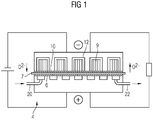
Figur 1 eine schematische Darstellung einer Zelle einer Rechargeable Oxide Battery, -
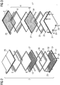
Figur 2 eine Explosionsdarstellung eines Stacks von oben betrachtet, -
Figur 3 eine Explosionsdarstellung des Stacks ausFigur 2 von unten betrachtet, -
Figur 4 einen Stack mit nach aussen offenen Kanälen für das Speichermedium, -
Figur 5 einen Stack in einem gasdichten mit Wasserdampf-Wasserstoff-Gemisch gefüllten Reservoir mit thermischer Isolierung und -
Figur 6 einen elektrischen Energiespeicher mit vier Stacks in einem Wasserdampf-Wasserstoff-Reservoir mit thermischer Isolierung. - Anhand von
Figur 1 soll zunächst schematisch die Wirkungsweise einer Rechargeable Oxide Batterie (ROB) beschrieben werden, insoweit dies für die vorliegende Beschreibung der Erfindung notwendig ist. Ein üblicher Aufbau einer ROB besteht darin, dass an einer positiven Elektrode 6, die auch als Luftelektrode bezeichnet wird, ein Prozessgas, insbesondere Luft, über eine Gaszufuhr 20 eingeblasen wird, wobei aus der Luft Sauerstoff entzogen wird. Der Sauerstoff gelangt in Form von Sauerstoffionen O2- durch einen an der positiven Elektrode anliegenden Feststoffelektrolyten 7, zu einer negativen Elektrode 10., die, wie beschrieben auch als Speicherelektrode bezeichnet wird. Würde nun an der negativen Elektrode 10 also an der Speicherelektrode eine dichte Schicht des aktiven Speichermaterials vorliegen, so würde die Ladekapazität der Batterie schnell erschöpft werden. - Aus diesem Grund ist es zweckmäßig, an der negativen Elektrode 10 als Energiespeichermedium ein Speichermedium 9 aus porösem Material einzusetzen, das ein funktional wirkendes oxidierbares Material als ein aktives Speichermaterial, bevorzugt in Form von Eisen und Eisenoxid enthält.
- Über ein, bei Betriebszustand der Batterie gasförmiges Redoxpaar, beispielsweise H2/H2O, wird der, in Form von O2- Ionen durch den Festkörperelektrolyten 7 transportierte Sauerstoff von der negativen Elektrode unter Zurücklassung der Elektronen durch Porenkanäle in dem porösen Speichermedium 9, in die Tiefe des aktiven Speichermaterials transportiert. Je nachdem ob ein Entlade- oder Ladevorgang vorliegt, wird das Metall bzw. das Metalloxid (Eisen/Eisenoxid) oxidiert oder reduziert und der hierfür benötigte Sauerstoff durch das gasförmige Redoxpaar H2/H2O angeliefert oder zum Festkörperelektrolyten 7 zurück transportiert. Dieser durch das gasförmige Redoxpaar getragene Sauerstoff-Transportmechanismus wird als Shuttle-Mechanismus bezeichnet.
- Der Vorteil des Eisens als oxidierbares Material, also als aktives Speichermaterial, besteht darin, dass es bei seinem Oxidationsprozess in etwa dieselbe Ruhespannung von etwa 1 V aufweist, wie das Redoxpaar H2/H2O bei einem Partialdruckverhältnis von 1, andernfalls ergibt sich ein erhöhter Widerstand für den Sauerstofftransport durch die diffundierenden Komponenten dieses Redoxpaares.
- Ein Vorteil der ROB besteht darin, dass sie durch Wiederholung ihrer kleinsten Einheit, nämlich der Speicherzelle 4 modular nahezu unbegrenzt erweiterbar ist. Somit ist eine kleine Batterie für den stationären Hausgebrauch ebenso darstellbar wie eine großtechnische Anlage zur Speicherung der Energie eines Kraftwerkes.
- Mehrere der in
Figur 1 beschriebenen Speicherzellen 4 sind zu einem sogenannten Stack 2 zusammengefasst. Der Aufbau eines Stacks 2 und die Anordnung der Speicherzellen 4 in dem Stack 2 ist anhand der Explosionsdarstellungen inFigur 2 und Figur 3 veranschaulicht. InFigur 2 ist der Aufbau eines Stacks dargestellt, der von oben betrachtet ist und hierbei in der Reihenfolge von unten nach oben zusammengesetzt wird. Der Stack 2 umfasst zunächst eine Bodenplatte 24, die gegebenenfalls aus mehreren Einzelplatten, die wiederum funktionale Strukturierungen und Vertiefungen beispielsweise zur Luftführung aufweisen, zusammengesetzt ist. Diese Zusammensetzung von Einzelplatten, die hier nicht näher beschrieben ist, zur Bodenplatte 24 erfolgt beispielsweise durch ein Hartlotverfahren. - Die Grundplatte 24 weist eine Luftzufuhr 20 sowie eine Luftabfuhr 22 auf. Wie bereits beschrieben, sind durch die Zusammensetzung von Einzelplatten in der Bodenplatte 24 hier nicht sichtbare Kanäle zur Luftzufuhr integriert. Ferner weist die Bodenplatte 24 Zentrierbolzen 29 auf, durch die nun weitere Komponenten des Stacks 2 zentriert aufgebracht werden können. Als nächste Schicht folgt eine Elektrodenstruktur 25, die insbesondere die bereits beschriebene positive Elektrode 6, den Festkörperelektrolyten 7 sowie die Speicherelektrode 10 umfasst. Hierbei handelt es sich um eine selbsttragende keramische Struktur, auf die die einzelnen funktionalen Bereiche wie die Elektroden bzw. Festkörperelektrolyt in einem Dünnschichtverfahren aufgebracht sind.
- Als weitere Schicht folgt eine Dichtung 26, die beispielsweise aus einer hochtemperaturbeständigen Glasfritte besteht, die die einzelnen Platten des Stacks 2 bei den Betriebstemperaturen der Batterie abdichtet. Die nächste folgende Platte ist eine sogenannte Interkonnektorplatte 27, die zwei funktional wirkende Seiten aufweist. An ihrer bezüglich
Figur 2 gesehenen unteren Seite 34 befinden sich die hier nicht näher dargestellten Luftzufuhrkanäle die an die positive Elektrode 6 einer Speicherzelle 4 grenzen. Auf ihrer Oberseite (Speicherseite 32) weist die Interkonnektorplatte 27 Kanäle 12 auf, in die das Speichermedium 9 eingebracht ist. Die Oberseite der Interkonnektorplatte 27 inFigur 2 weist dieselbe Struktur auf wie die Oberseite der Grundplatte 24. Auch hier sind die Kanäle 12 zur Einbringung des Speichermediums 9 vorgesehen. Diese Seite mit den Kanälen 12 ist jeweils der Speicherelektrode 10 der Speicherzelle 4 zugewandt. - Exemplarisch ist in
Figur 2 eine weitere Ebene der Folge von Elektrodenstruktur 25, Dichtung 26 unter einer Abschlussplatte 28 zum Gesamtaufbau des Stacks 2 dargestellt. Grundsätzlich können selbstverständlich noch eine Reihe weiterer Ebenen dieser Bauteile folgen, so dass ein Stack üblicherweise zwischen 10 und mehr Schichten von Speicherzellen 4 aufweist. - In
Figur 3 ist derselbe Stack 2, der in derFigur 2 beschrieben ist, in umgekehrter Blickrichtung dargestellt. InFigur 3 blickt man von unten auf die Grundplatte 24, es folgt wiederum die Elektrodenstruktur 25 und die Dichtung 26. Die Interkonnektorplatte 27 ist nun ebenfalls von unten sichtbar, wobei hierbei der Blick auf die Luftseite 34 gelenkt ist, die der Luftelektrode zugewandt ist (Luftseite 34). In diesem Beispiel sind auf der Interkonnektorplatte vier getrennte Bereiche auf der Luftseite 34 dargestellt, die einer Unterteilung in vier einzelne Speicherzellen 4 pro Stackebene entsprechen (wobei diese Unterteilung in vier Speicherzellen als rein exemplarisch anzusehen ist). Die Speicherzelle 4 setzt sich somit in diesem Beispiel aus einem Viertel der Fläche der jeweiligen Interkonnektorplatte bzw. der Grundplatte 24 bzw. der Deckplatte 28 zusammen. Ferner wird die jeweilige Zelle 4 durch eine Abfolge der jeweiligen Luftseite 34, Dichtung 26, Elektrodenstruktur 25 und wiederum jeweils ein Viertel der Speicherseite 32 der Grundplatte 24 bzw. der Interkonnektorplatte 27 gebildet. Die Luftseite 34 wird hierbei durch eine hier nicht näher dargestellte stackinterne Luftverteilungsvorrichtung 8 (auch Manifold genannt), die mehrere Ebenen des Stacks umfasst, mit dem Prozessgas Luft versorgt. - In
Figur 4 ist ein Stack 2 gemäßFigur 2 und 3 in zusammengebauter Form dargestellt. Es ist von außen die Luftzufuhr 20 sowie die Luftabfuhr 22 zu erkennen, durch gestrichelte Linien ist die im Inneren angeordnete Luftverteilungsvorrichtung 8 schematisch dargestellt. Die Luftverteilungsvorrichtung 8 umfasst dabei sowohl den Lufteinlass 20, den Luftauslass 22 sowie nicht näher benannte Kanäle in der Grundplatte 24 sowie im seitlichen Bereich des zusammengesetzten Stacks 2. Atmosphärisch getrennt davon sind die Kanäle 12 angeordnet, die sich jeweils auf der Speicherseite 32 der Grundplatte 24 bzw. der Interkonnektorplatte 27 befinden. In den Kanälen 12 ist, wie inFigur 5 näher zu erkennen ist, das Speichermedium 9 eingebracht. In der hier vorliegenden Ausgestaltungsform sind die Kanäle 12 bezüglich einer Stack-Wand 16 offen zugänglich. Der Stack 2 kann somit, wie das inFigur 5 schematisch dargestellt ist, in einen geschlossenen Raum gebracht werden, in dem wiederum eine H2/H2O-Atmosphäre herrscht. Dieser geschlossene Raum mit der H2/H2O-Atmosphäre wird als Reservoir 14 bezeichnet. Das Reservoir 14 weist dabei bevorzugt einen Überdruck des Reaktionspaares H2/H2O von etwa 1-100 hPa auf. Hiermit wird gewährleistet, dass bei einer möglichen Leckage des Reservoirs 14 kein Stickstoff und Sauerstoff von außen in das Reservoir 14 eindringt, sondern dass in diesem Fall eher in unschädlicher Weise H2/H2O aus dem Reservoir entweichen kann, wobei dieser Verlust durch Stromfluss und eine Wasserdampfzuführung 30 über ein Ventil 31 ausgeglichen werden kann. Es wäre ebenso gut möglich anstatt reinem Wasserdampf ein Wasserstoff-Wasserdampf-Gemisch zuzuführen, oder aber auch reinen Wasserstoff. Die gesamte Anordnung gemäßFigur 5 mit dem Stack 2 und dem Reservoir 14, das durch eine thermische Isolierung 18 umschlossen ist, die auch als sogenannte Hotbox bezeichnet wird, wird als elektrischer Energiespeicher 1 bezeichnet. - Hierbei sind auch komplexere elektrische Energiespeicher 1 zweckmäßig, in denen mehrere Stacks 2 angeordnet sind (
Figur 6 ). Hierbei kann eine zentrale Luftzufuhr 20 und eine zentrale Luftabfuhr 22 vorgesehen sein, wobei hierdurch die einzelnen Stacks 2 durch eine entsprechende Leitung 20 mit dem Prozessgas Luft versorgt werden. In der Hotbox 18 herrscht nahezu die Betriebstemperatur des elektrischen Energiespeichers vor, die üblicherweise zwischen 600°C und 800°C liegt. Grundsätzlich können in der Hotbox 18 auch noch weitere Anordnungen zur Wärmespeicherung beispielsweise ein Latentwärmespeicher, der hier nicht dargestellt ist, angeordnet sein.
Claims (6)
- Elektrischer Energiespeicher mit mehr als einem Stack (2) mit jeweils mindestens einer Speicherzelle (4), die wiederum eine Luftelektrode (6), die mit einer Luftzufuhrvorrichtung (8) in Verbindung steht und eine Speicherelektrode (10) umfasst wobei die Speicherelektrode (10) an Kanäle (12) angrenzt, die ein Speichermedium (9) und Wasserdampf enthalten, wobei ein Reservoir (14) an Wasserdampf vorgesehen ist, dass mit den Kanälen (12) in direkter Verbindung steht und das Wasserdampf-Reservoir (14) mehrere Stacks (2) umschließt.
- Elektrischer Energiespeicher nach Anspruch 1, dadurch gekennzeichnet, dass die Kanäle (12) zu einer Stack-Wand (16) hin offen zugänglich sind.
- Elektrischer Energiespeicher nach Anspruch 2, dadurch gekennzeichnet, dass das Wasserdampf-Reservoir (14) die Stack-Wand (16) umgibt an der die Kanäle (12) offen zugänglich sind.
- Elektrischer Energiespeicher nach einem der vorhergehenden Ansprüche, dadurch gekennzeichnet, dass das Wasserdampf-Reservoir (14) den gesamten Stack (2) umgibt.
- Elektrischer Energiespeicher nach einem der vorhergehenden Ansprüche, dadurch gekennzeichnet, dass das Wasserdampf-Reservoir (14) nach außen thermisch isoliert ist.
- Elektrischer Energiespeicher nach einem der vorhergehenden Ansprüche, dadurch gekennzeichnet, dass im Wasserdampf-Reservoir (14) ein Überdruck vorherrscht.
Applications Claiming Priority (2)
| Application Number | Priority Date | Filing Date | Title |
|---|---|---|---|
| DE201210205077 DE102012205077A1 (de) | 2012-03-12 | 2012-03-29 | Elektrischer Energiespeicher |
| PCT/EP2013/055680 WO2013143921A1 (de) | 2012-03-29 | 2013-03-19 | Elektrischer energiespeicher |
Publications (2)
| Publication Number | Publication Date |
|---|---|
| EP2810332A1 EP2810332A1 (de) | 2014-12-10 |
| EP2810332B1 true EP2810332B1 (de) | 2018-11-28 |
Family
ID=48045430
Family Applications (1)
| Application Number | Title | Priority Date | Filing Date |
|---|---|---|---|
| EP13713775.8A Active EP2810332B1 (de) | 2012-03-29 | 2013-03-19 | Elektrischer energiespeicher |
Country Status (4)
| Country | Link |
|---|---|
| EP (1) | EP2810332B1 (de) |
| JP (1) | JP5977432B2 (de) |
| CN (1) | CN104205462B (de) |
| WO (1) | WO2013143921A1 (de) |
Families Citing this family (3)
| Publication number | Priority date | Publication date | Assignee | Title |
|---|---|---|---|---|
| DE102012205077A1 (de) | 2012-03-12 | 2013-09-12 | Siemens Aktiengesellschaft | Elektrischer Energiespeicher |
| DE102012217290A1 (de) | 2012-09-25 | 2014-03-27 | Siemens Aktiengesellschaft | Elektrischer Energiespeicher |
| WO2015138790A1 (en) * | 2014-03-12 | 2015-09-17 | Hifunda Llc | Grid-scale solid state electrochemical energy storge systems |
Family Cites Families (9)
| Publication number | Priority date | Publication date | Assignee | Title |
|---|---|---|---|---|
| US5492777A (en) * | 1995-01-25 | 1996-02-20 | Westinghouse Electric Corporation | Electrochemical energy conversion and storage system |
| JP2009099491A (ja) * | 2007-10-19 | 2009-05-07 | Sharp Corp | 燃料電池システムおよび電子機器 |
| WO2010100749A1 (ja) * | 2009-03-06 | 2010-09-10 | トヨタ自動車株式会社 | 空気電池 |
| DE102009057720A1 (de) * | 2009-12-10 | 2011-06-16 | Siemens Aktiengesellschaft | Batterie und Verfahren zum Betreiben einer Batterie |
| JP5516735B2 (ja) * | 2010-07-15 | 2014-06-11 | コニカミノルタ株式会社 | 燃料電池 |
| DE102010027690A1 (de) * | 2010-07-20 | 2012-01-26 | Siemens Aktiengesellschaft | Energiespeichervorrichtung und Verfahren zum reversiblen Speichern von Energie |
| WO2012098945A1 (ja) * | 2011-01-20 | 2012-07-26 | コニカミノルタホールディングス株式会社 | 2次電池型燃料電池システム |
| JP5640884B2 (ja) * | 2011-05-06 | 2014-12-17 | コニカミノルタ株式会社 | 2次電池型燃料電池システム |
| DE102011078116A1 (de) * | 2011-06-27 | 2012-12-27 | Siemens Ag | Energiespeicher und Verfahren zum Laden oder Entladen eines Energiespeichers |
-
2013
- 2013-03-19 EP EP13713775.8A patent/EP2810332B1/de active Active
- 2013-03-19 CN CN201380015397.5A patent/CN104205462B/zh active Active
- 2013-03-19 WO PCT/EP2013/055680 patent/WO2013143921A1/de not_active Ceased
- 2013-03-19 JP JP2015502209A patent/JP5977432B2/ja active Active
Non-Patent Citations (1)
| Title |
|---|
| None * |
Also Published As
| Publication number | Publication date |
|---|---|
| EP2810332A1 (de) | 2014-12-10 |
| CN104205462B (zh) | 2017-01-18 |
| CN104205462A (zh) | 2014-12-10 |
| JP2015516651A (ja) | 2015-06-11 |
| WO2013143921A1 (de) | 2013-10-03 |
| JP5977432B2 (ja) | 2016-08-24 |
Similar Documents
| Publication | Publication Date | Title |
|---|---|---|
| EP2510573B1 (de) | Batterie | |
| EP2956981B1 (de) | Energiewandlerzelle mit elektrochemischer wandlereinheit | |
| EP2810332B1 (de) | Elektrischer energiespeicher | |
| EP2789038B1 (de) | Stack für einen elektrischen energiespeicher | |
| DE102012205077A1 (de) | Elektrischer Energiespeicher | |
| EP2885836B1 (de) | Elektrischer energiespeicher | |
| DE102011005599B4 (de) | Elektrischer Energiespeicher und Verfahren zum Betreiben eines elektrischen Energiespeichers | |
| EP2850676B1 (de) | Speicherstruktur einer elektrischen energiespeicherzelle | |
| WO2013110509A2 (de) | Elektrischer energiespeicher | |
| DE102012211318A1 (de) | Elektrischer Energiespeicher | |
| EP2850687B1 (de) | Elektrischer energiespeicher | |
| DE102015117087A1 (de) | Membranelektrodenanordnung und Brennstoffzellenbatterie | |
| DE102012213037A1 (de) | Speichereinrichtung für elektrische Energie, insbesondere Batterie oder Batteriezelle | |
| DE102012211322A1 (de) | Elektrischer Energiespeicher | |
| DE19819324A1 (de) | Verfahren zur Benetzung wenigstens einer der Oberflächen eines Elektrolyten in einer Brennstoffzelle | |
| DE102011077699B4 (de) | Verfahren zur Herstellung eines porösen Körpers und Zelle einer wieder aufladbaren Oxidbatterie | |
| DE102012223794A1 (de) | Wiederaufladbarer elektrischer Energiespeicher, insbesondere in Form eines Metalloxid-Luft-Energiespeichers, mit wenigstens einem wenigstens ein Speichermaterial zur Speicherung elektrischer Energie umfassenden Speicherelement | |
| EP4342013A1 (de) | Behandlung wasserstoffhaltiger und sauerstoffhaltiger restgase von brennstoffzellen | |
| DE102012204171A1 (de) | Speicherstruktur einer elektrischen Energiespeicherzelle | |
| DE102013020785A1 (de) | Fahrzeug mit mindestens einem Brennstoffzellenmodul sowie Verfahren zur Herstellung eines Fahrzeugs | |
| WO2014000991A1 (de) | Speicherstruktur einer elektrischen energiespeicherzelle |
Legal Events
| Date | Code | Title | Description |
|---|---|---|---|
| PUAI | Public reference made under article 153(3) epc to a published international application that has entered the european phase |
Free format text: ORIGINAL CODE: 0009012 |
|
| 17P | Request for examination filed |
Effective date: 20140902 |
|
| AK | Designated contracting states |
Kind code of ref document: A1 Designated state(s): AL AT BE BG CH CY CZ DE DK EE ES FI FR GB GR HR HU IE IS IT LI LT LU LV MC MK MT NL NO PL PT RO RS SE SI SK SM TR |
|
| AX | Request for extension of the european patent |
Extension state: BA ME |
|
| DAX | Request for extension of the european patent (deleted) | ||
| 17Q | First examination report despatched |
Effective date: 20161013 |
|
| STAA | Information on the status of an ep patent application or granted ep patent |
Free format text: STATUS: EXAMINATION IS IN PROGRESS |
|
| RAP1 | Party data changed (applicant data changed or rights of an application transferred) |
Owner name: SIEMENS AKTIENGESELLSCHAFT |
|
| REG | Reference to a national code |
Ref country code: DE Ref legal event code: R079 Ref document number: 502013011715 Country of ref document: DE Free format text: PREVIOUS MAIN CLASS: H01M0008240000 Ipc: H01M0012080000 |
|
| GRAP | Despatch of communication of intention to grant a patent |
Free format text: ORIGINAL CODE: EPIDOSNIGR1 |
|
| STAA | Information on the status of an ep patent application or granted ep patent |
Free format text: STATUS: GRANT OF PATENT IS INTENDED |
|
| INTG | Intention to grant announced |
Effective date: 20180720 |
|
| RIC1 | Information provided on ipc code assigned before grant |
Ipc: H01M 12/08 20060101AFI20180706BHEP Ipc: H01M 8/18 20060101ALN20180706BHEP Ipc: H01M 8/2475 20160101ALI20180706BHEP Ipc: H01M 8/04007 20160101ALN20180706BHEP Ipc: H01M 8/04082 20160101ALI20180706BHEP |
|
| GRAS | Grant fee paid |
Free format text: ORIGINAL CODE: EPIDOSNIGR3 |
|
| GRAA | (expected) grant |
Free format text: ORIGINAL CODE: 0009210 |
|
| STAA | Information on the status of an ep patent application or granted ep patent |
Free format text: STATUS: THE PATENT HAS BEEN GRANTED |
|
| AK | Designated contracting states |
Kind code of ref document: B1 Designated state(s): AL AT BE BG CH CY CZ DE DK EE ES FI FR GB GR HR HU IE IS IT LI LT LU LV MC MK MT NL NO PL PT RO RS SE SI SK SM TR |
|
| REG | Reference to a national code |
Ref country code: CH Ref legal event code: EP |
|
| REG | Reference to a national code |
Ref country code: AT Ref legal event code: REF Ref document number: 1071316 Country of ref document: AT Kind code of ref document: T Effective date: 20181215 |
|
| REG | Reference to a national code |
Ref country code: DE Ref legal event code: R096 Ref document number: 502013011715 Country of ref document: DE |
|
| REG | Reference to a national code |
Ref country code: IE Ref legal event code: FG4D Free format text: LANGUAGE OF EP DOCUMENT: GERMAN |
|
| REG | Reference to a national code |
Ref country code: NL Ref legal event code: MP Effective date: 20181128 |
|
| REG | Reference to a national code |
Ref country code: LT Ref legal event code: MG4D |
|
| PG25 | Lapsed in a contracting state [announced via postgrant information from national office to epo] |
Ref country code: LT Free format text: LAPSE BECAUSE OF FAILURE TO SUBMIT A TRANSLATION OF THE DESCRIPTION OR TO PAY THE FEE WITHIN THE PRESCRIBED TIME-LIMIT Effective date: 20181128 Ref country code: HR Free format text: LAPSE BECAUSE OF FAILURE TO SUBMIT A TRANSLATION OF THE DESCRIPTION OR TO PAY THE FEE WITHIN THE PRESCRIBED TIME-LIMIT Effective date: 20181128 Ref country code: NO Free format text: LAPSE BECAUSE OF FAILURE TO SUBMIT A TRANSLATION OF THE DESCRIPTION OR TO PAY THE FEE WITHIN THE PRESCRIBED TIME-LIMIT Effective date: 20190228 Ref country code: BG Free format text: LAPSE BECAUSE OF FAILURE TO SUBMIT A TRANSLATION OF THE DESCRIPTION OR TO PAY THE FEE WITHIN THE PRESCRIBED TIME-LIMIT Effective date: 20190228 Ref country code: IS Free format text: LAPSE BECAUSE OF FAILURE TO SUBMIT A TRANSLATION OF THE DESCRIPTION OR TO PAY THE FEE WITHIN THE PRESCRIBED TIME-LIMIT Effective date: 20190328 Ref country code: ES Free format text: LAPSE BECAUSE OF FAILURE TO SUBMIT A TRANSLATION OF THE DESCRIPTION OR TO PAY THE FEE WITHIN THE PRESCRIBED TIME-LIMIT Effective date: 20181128 Ref country code: FI Free format text: LAPSE BECAUSE OF FAILURE TO SUBMIT A TRANSLATION OF THE DESCRIPTION OR TO PAY THE FEE WITHIN THE PRESCRIBED TIME-LIMIT Effective date: 20181128 Ref country code: LV Free format text: LAPSE BECAUSE OF FAILURE TO SUBMIT A TRANSLATION OF THE DESCRIPTION OR TO PAY THE FEE WITHIN THE PRESCRIBED TIME-LIMIT Effective date: 20181128 |
|
| PG25 | Lapsed in a contracting state [announced via postgrant information from national office to epo] |
Ref country code: GR Free format text: LAPSE BECAUSE OF FAILURE TO SUBMIT A TRANSLATION OF THE DESCRIPTION OR TO PAY THE FEE WITHIN THE PRESCRIBED TIME-LIMIT Effective date: 20190301 Ref country code: RS Free format text: LAPSE BECAUSE OF FAILURE TO SUBMIT A TRANSLATION OF THE DESCRIPTION OR TO PAY THE FEE WITHIN THE PRESCRIBED TIME-LIMIT Effective date: 20181128 Ref country code: SE Free format text: LAPSE BECAUSE OF FAILURE TO SUBMIT A TRANSLATION OF THE DESCRIPTION OR TO PAY THE FEE WITHIN THE PRESCRIBED TIME-LIMIT Effective date: 20181128 Ref country code: AL Free format text: LAPSE BECAUSE OF FAILURE TO SUBMIT A TRANSLATION OF THE DESCRIPTION OR TO PAY THE FEE WITHIN THE PRESCRIBED TIME-LIMIT Effective date: 20181128 Ref country code: PT Free format text: LAPSE BECAUSE OF FAILURE TO SUBMIT A TRANSLATION OF THE DESCRIPTION OR TO PAY THE FEE WITHIN THE PRESCRIBED TIME-LIMIT Effective date: 20190328 |
|
| PG25 | Lapsed in a contracting state [announced via postgrant information from national office to epo] |
Ref country code: NL Free format text: LAPSE BECAUSE OF FAILURE TO SUBMIT A TRANSLATION OF THE DESCRIPTION OR TO PAY THE FEE WITHIN THE PRESCRIBED TIME-LIMIT Effective date: 20181128 |
|
| PG25 | Lapsed in a contracting state [announced via postgrant information from national office to epo] |
Ref country code: DK Free format text: LAPSE BECAUSE OF FAILURE TO SUBMIT A TRANSLATION OF THE DESCRIPTION OR TO PAY THE FEE WITHIN THE PRESCRIBED TIME-LIMIT Effective date: 20181128 Ref country code: PL Free format text: LAPSE BECAUSE OF FAILURE TO SUBMIT A TRANSLATION OF THE DESCRIPTION OR TO PAY THE FEE WITHIN THE PRESCRIBED TIME-LIMIT Effective date: 20181128 Ref country code: IT Free format text: LAPSE BECAUSE OF FAILURE TO SUBMIT A TRANSLATION OF THE DESCRIPTION OR TO PAY THE FEE WITHIN THE PRESCRIBED TIME-LIMIT Effective date: 20181128 Ref country code: CZ Free format text: LAPSE BECAUSE OF FAILURE TO SUBMIT A TRANSLATION OF THE DESCRIPTION OR TO PAY THE FEE WITHIN THE PRESCRIBED TIME-LIMIT Effective date: 20181128 |
|
| REG | Reference to a national code |
Ref country code: DE Ref legal event code: R097 Ref document number: 502013011715 Country of ref document: DE |
|
| PG25 | Lapsed in a contracting state [announced via postgrant information from national office to epo] |
Ref country code: RO Free format text: LAPSE BECAUSE OF FAILURE TO SUBMIT A TRANSLATION OF THE DESCRIPTION OR TO PAY THE FEE WITHIN THE PRESCRIBED TIME-LIMIT Effective date: 20181128 Ref country code: SM Free format text: LAPSE BECAUSE OF FAILURE TO SUBMIT A TRANSLATION OF THE DESCRIPTION OR TO PAY THE FEE WITHIN THE PRESCRIBED TIME-LIMIT Effective date: 20181128 Ref country code: EE Free format text: LAPSE BECAUSE OF FAILURE TO SUBMIT A TRANSLATION OF THE DESCRIPTION OR TO PAY THE FEE WITHIN THE PRESCRIBED TIME-LIMIT Effective date: 20181128 Ref country code: SK Free format text: LAPSE BECAUSE OF FAILURE TO SUBMIT A TRANSLATION OF THE DESCRIPTION OR TO PAY THE FEE WITHIN THE PRESCRIBED TIME-LIMIT Effective date: 20181128 |
|
| PLBE | No opposition filed within time limit |
Free format text: ORIGINAL CODE: 0009261 |
|
| STAA | Information on the status of an ep patent application or granted ep patent |
Free format text: STATUS: NO OPPOSITION FILED WITHIN TIME LIMIT |
|
| PG25 | Lapsed in a contracting state [announced via postgrant information from national office to epo] |
Ref country code: MC Free format text: LAPSE BECAUSE OF FAILURE TO SUBMIT A TRANSLATION OF THE DESCRIPTION OR TO PAY THE FEE WITHIN THE PRESCRIBED TIME-LIMIT Effective date: 20181128 Ref country code: SI Free format text: LAPSE BECAUSE OF FAILURE TO SUBMIT A TRANSLATION OF THE DESCRIPTION OR TO PAY THE FEE WITHIN THE PRESCRIBED TIME-LIMIT Effective date: 20181128 |
|
| REG | Reference to a national code |
Ref country code: CH Ref legal event code: PL |
|
| 26N | No opposition filed |
Effective date: 20190829 |
|
| PG25 | Lapsed in a contracting state [announced via postgrant information from national office to epo] |
Ref country code: LU Free format text: LAPSE BECAUSE OF NON-PAYMENT OF DUE FEES Effective date: 20190319 |
|
| REG | Reference to a national code |
Ref country code: BE Ref legal event code: MM Effective date: 20190331 |
|
| PG25 | Lapsed in a contracting state [announced via postgrant information from national office to epo] |
Ref country code: LI Free format text: LAPSE BECAUSE OF NON-PAYMENT OF DUE FEES Effective date: 20190331 Ref country code: CH Free format text: LAPSE BECAUSE OF NON-PAYMENT OF DUE FEES Effective date: 20190331 Ref country code: IE Free format text: LAPSE BECAUSE OF NON-PAYMENT OF DUE FEES Effective date: 20190319 |
|
| PG25 | Lapsed in a contracting state [announced via postgrant information from national office to epo] |
Ref country code: BE Free format text: LAPSE BECAUSE OF NON-PAYMENT OF DUE FEES Effective date: 20190331 |
|
| PG25 | Lapsed in a contracting state [announced via postgrant information from national office to epo] |
Ref country code: TR Free format text: LAPSE BECAUSE OF FAILURE TO SUBMIT A TRANSLATION OF THE DESCRIPTION OR TO PAY THE FEE WITHIN THE PRESCRIBED TIME-LIMIT Effective date: 20181128 |
|
| PG25 | Lapsed in a contracting state [announced via postgrant information from national office to epo] |
Ref country code: MT Free format text: LAPSE BECAUSE OF FAILURE TO SUBMIT A TRANSLATION OF THE DESCRIPTION OR TO PAY THE FEE WITHIN THE PRESCRIBED TIME-LIMIT Effective date: 20181128 |
|
| REG | Reference to a national code |
Ref country code: AT Ref legal event code: MM01 Ref document number: 1071316 Country of ref document: AT Kind code of ref document: T Effective date: 20190319 |
|
| PG25 | Lapsed in a contracting state [announced via postgrant information from national office to epo] |
Ref country code: AT Free format text: LAPSE BECAUSE OF NON-PAYMENT OF DUE FEES Effective date: 20190319 |
|
| REG | Reference to a national code |
Ref country code: DE Ref legal event code: R081 Ref document number: 502013011715 Country of ref document: DE Owner name: SIEMENS ENERGY GLOBAL GMBH & CO. KG, DE Free format text: FORMER OWNER: SIEMENS AKTIENGESELLSCHAFT, 80333 MUENCHEN, DE |
|
| PG25 | Lapsed in a contracting state [announced via postgrant information from national office to epo] |
Ref country code: CY Free format text: LAPSE BECAUSE OF FAILURE TO SUBMIT A TRANSLATION OF THE DESCRIPTION OR TO PAY THE FEE WITHIN THE PRESCRIBED TIME-LIMIT Effective date: 20181128 |
|
| PG25 | Lapsed in a contracting state [announced via postgrant information from national office to epo] |
Ref country code: HU Free format text: LAPSE BECAUSE OF FAILURE TO SUBMIT A TRANSLATION OF THE DESCRIPTION OR TO PAY THE FEE WITHIN THE PRESCRIBED TIME-LIMIT; INVALID AB INITIO Effective date: 20130319 |
|
| PG25 | Lapsed in a contracting state [announced via postgrant information from national office to epo] |
Ref country code: MK Free format text: LAPSE BECAUSE OF FAILURE TO SUBMIT A TRANSLATION OF THE DESCRIPTION OR TO PAY THE FEE WITHIN THE PRESCRIBED TIME-LIMIT Effective date: 20181128 |
|
| REG | Reference to a national code |
Ref country code: GB Ref legal event code: 732E Free format text: REGISTERED BETWEEN 20220908 AND 20220914 |
|
| PGFP | Annual fee paid to national office [announced via postgrant information from national office to epo] |
Ref country code: DE Payment date: 20250327 Year of fee payment: 13 |
|
| PGFP | Annual fee paid to national office [announced via postgrant information from national office to epo] |
Ref country code: FR Payment date: 20250324 Year of fee payment: 13 |
|
| PGFP | Annual fee paid to national office [announced via postgrant information from national office to epo] |
Ref country code: GB Payment date: 20250325 Year of fee payment: 13 |