EP2811175A1 - Einstellungs- und Verriegelungsmechanismus - Google Patents
Einstellungs- und Verriegelungsmechanismus Download PDFInfo
- Publication number
- EP2811175A1 EP2811175A1 EP14167695.7A EP14167695A EP2811175A1 EP 2811175 A1 EP2811175 A1 EP 2811175A1 EP 14167695 A EP14167695 A EP 14167695A EP 2811175 A1 EP2811175 A1 EP 2811175A1
- Authority
- EP
- European Patent Office
- Prior art keywords
- aperture
- arm
- locking mechanism
- valve
- adjustment mechanism
- Prior art date
- Legal status (The legal status is an assumption and is not a legal conclusion. Google has not performed a legal analysis and makes no representation as to the accuracy of the status listed.)
- Withdrawn
Links
- 230000007246 mechanism Effects 0.000 title claims abstract description 91
- 239000000446 fuel Substances 0.000 claims description 22
- 239000012530 fluid Substances 0.000 claims description 12
- 238000000034 method Methods 0.000 description 9
- 238000006073 displacement reaction Methods 0.000 description 4
- 230000001105 regulatory effect Effects 0.000 description 4
- 238000005516 engineering process Methods 0.000 description 3
- 230000013011 mating Effects 0.000 description 3
- KJLPSBMDOIVXSN-UHFFFAOYSA-N 4-[4-[2-[4-(3,4-dicarboxyphenoxy)phenyl]propan-2-yl]phenoxy]phthalic acid Chemical compound C=1C=C(OC=2C=C(C(C(O)=O)=CC=2)C(O)=O)C=CC=1C(C)(C)C(C=C1)=CC=C1OC1=CC=C(C(O)=O)C(C(O)=O)=C1 KJLPSBMDOIVXSN-UHFFFAOYSA-N 0.000 description 2
- 238000013461 design Methods 0.000 description 2
- 230000001360 synchronised effect Effects 0.000 description 2
- 230000005484 gravity Effects 0.000 description 1
- 239000000463 material Substances 0.000 description 1
- 238000005259 measurement Methods 0.000 description 1
- 238000012986 modification Methods 0.000 description 1
- 230000004048 modification Effects 0.000 description 1
- 238000012544 monitoring process Methods 0.000 description 1
- 230000000717 retained effect Effects 0.000 description 1
Images

Classifications
-
- F—MECHANICAL ENGINEERING; LIGHTING; HEATING; WEAPONS; BLASTING
- F16—ENGINEERING ELEMENTS AND UNITS; GENERAL MEASURES FOR PRODUCING AND MAINTAINING EFFECTIVE FUNCTIONING OF MACHINES OR INSTALLATIONS; THERMAL INSULATION IN GENERAL
- F16K—VALVES; TAPS; COCKS; ACTUATING-FLOATS; DEVICES FOR VENTING OR AERATING
- F16K35/00—Means to prevent accidental or unauthorised actuation
-
- F—MECHANICAL ENGINEERING; LIGHTING; HEATING; WEAPONS; BLASTING
- F02—COMBUSTION ENGINES; HOT-GAS OR COMBUSTION-PRODUCT ENGINE PLANTS
- F02C—GAS-TURBINE PLANTS; AIR INTAKES FOR JET-PROPULSION PLANTS; CONTROLLING FUEL SUPPLY IN AIR-BREATHING JET-PROPULSION PLANTS
- F02C7/00—Features, components parts, details or accessories, not provided for in, or of interest apart form groups F02C1/00 - F02C6/00; Air intakes for jet-propulsion plants
- F02C7/22—Fuel supply systems
- F02C7/232—Fuel valves; Draining valves or systems
-
- F—MECHANICAL ENGINEERING; LIGHTING; HEATING; WEAPONS; BLASTING
- F16—ENGINEERING ELEMENTS AND UNITS; GENERAL MEASURES FOR PRODUCING AND MAINTAINING EFFECTIVE FUNCTIONING OF MACHINES OR INSTALLATIONS; THERMAL INSULATION IN GENERAL
- F16B—DEVICES FOR FASTENING OR SECURING CONSTRUCTIONAL ELEMENTS OR MACHINE PARTS TOGETHER, e.g. NAILS, BOLTS, CIRCLIPS, CLAMPS, CLIPS OR WEDGES; JOINTS OR JOINTING
- F16B2/00—Friction-grip releasable fastenings
- F16B2/02—Clamps, i.e. with gripping action effected by positive means other than the inherent resistance to deformation of the material of the fastening
- F16B2/18—Clamps, i.e. with gripping action effected by positive means other than the inherent resistance to deformation of the material of the fastening using cams, levers, eccentrics, or toggles
Definitions
- This disclosure relates fluid delivery systems, and more particularly, to an assembly to facilitate the locking and adjustment of valve components for metering and control of fluid delivery systems.
- fuel delivery systems for aircraft gas turbine engines use a fixed positive displacement pump, such as a vane or gear pump, to pressurize fuel for subsequent delivery to the engine.
- the fixed positive displacement pump provides a flow whose volume is a function of the speed at which the pump is rotating.
- the relation of the change in volumetric output for a change in speed is linear in nature.
- the demand for fuel increases as the speed of the turbine increases, although when measured as a function of the percentage of pump output, demand for fuel is greatest at either low speeds (engine start) or at high speeds (take-off) and is lower during normal flight operation.
- the excess fuel output from the fixed positive displacement pump must be bypassed from the fuel control back to the input of the fixed positive displacement pump or to a fuel reservoir. Therefore, in order to provide the desired flow of fuel to the turbine and other components of the fuel system must be regulated through the use of valves including a metering valve.
- valves Operation of valves is based upon incompressible flow theory which states that flow through a valve is a function of the area of the valve opening multiplied by the square root of the product of the pressure drop across the valve multiplied by the specific gravity of the fluid.
- a pressure regulating valve controls pressure drop across the metering valve and compensates for temperature variations in the fuel. As a result, the flow though the metering valve can be precisely controlled by varying the area of the opening of the metering valve window.
- the flow out of the valves and/or pump(s) can be measured by a flow meter.
- the metered flow is calculated using a linear variable differential transformer "LVDT". This allows for measurement of the area of the metering window.
- the pressure drop across the window is maintained at a known value by the pressure regulating valve.
- the metered flow rate is then compared to the output flow rate to determine the presence of excess flow.
- the LVDT To calibrate the fuel control system to the fuel system, the LVDT must be adjusted to set a precise output ratio that corresponds to the mechanical window of the valve so that the electrical system is synchronized to flow through the valve.
- the calibration process requires a portion of the valve to be disassembled and specially designed tools are used to adjust the position of the LVDT. In some instances, one tool is used to make the adjustment to the LVDT and a second tool is used to lock down the LVDT. Unfortunately, locking down the LVDT tends to alter the just completed repositioning of the LVDT. Thus, the process of adjustment and locking down the LVDT must be repeated. The process is a repetitious trial and error process until a desired LVDT positioning is finally achieved. Because of its repetitious nature, the process of adjustment and locking down of the LVDT can be tedious and time consuming.
- a locking mechanism includes a connection portion, a first arm, a second arm, and a fastener.
- the first arm extends from the connection portion and defines a first aperture and a second aperture.
- the second arm extends from the connection portion and defines a third aperture.
- the first arm is spaced from the second arm by a notch.
- the fastener is adapted to extend through the first aperture and across the notch to abut the second arm.
- a valve includes a housing, a linear variable differential transformer, and a locking mechanism.
- the housing includes one or more ports for receiving a fluid.
- the linear variable differential transformer extends within the housing and has an adjustment mechanism with a rod.
- the locking mechanism is adapted to receive the rod and is configured as a hinge to apply a locking torsion force that is distributed over a plurality of threads of the rod.
- a fuel system for an engine includes a valve that has a linear variable differential transformer with an adjustment mechanism and a locking mechanism for retaining the adjustment mechanism.
- the adjustment mechanism includes a connection portion, a first arm, a second arm, and a fastener.
- the first arm extends from the connection portion and defines a first aperture and a second aperture.
- the second arm extends from the connection portion and defines a third aperture.
- the first arm is spaced from the second arm by a notch, and the second aperture and the third aperture receive the adjustment mechanism.
- the fastener is adapted to extend through the first aperture and across the notch to abut the second arm.
- the application discloses embodiments of a locking mechanism and an adjustment mechanism. Although described in reference to fluid systems such as fuel delivery systems for gas turbine engines, the disclosure is also applicable to other technologies, particularly technologies where precise adjustment and control of components is desired such as in the laser and optics industries.
- the locking mechanism is adapted to receive the adjustment mechanism in a threaded engagement and allows for movement of the adjustment mechanism relative thereto for calibration purposes.
- the locking mechanism includes a collar that is adapted as a hinge to apply a locking torsion force into the adjustment mechanism when a fastener is threaded into abutment with a portion the locking collar. The locking torsion force is distributed over a plurality of threads of the adjustment mechanism, which allows for a finer thread to be used.
- the finer thread allows for more precise adjustment of the adjustment mechanism and easier calibration of the LVDT. Additionally, due to the design of the collar, the application of the locking torsion force by the locking mechanism has minimal to no impact on the positioning of the adjustment mechanism. To make adjustments to calibrate the LVDT, personnel simply releases the locking torsion force by releasing the fastener from abutment with the collar, adjusts the adjustment mechanism to a desired position, and then tightens the fastener back into adjustment with the collar to generate the locking torsion force. Thus, personnel does not have to undergo a repetitious trial and error process to calibrate the LVDT. Additionally, the locking mechanism and adjustment mechanism allow a standard Allen wrench to be used, eliminating the need for special tooling from the calibration process.
- the LVDT 14 and the locking mechanism 16 extend within an interior of the hollow spool 18. Additionally, the locking mechanism 16 is mounted to the spool 18. The spool 18 is disposed within the hollow sleeve 20. The sleeve 20 is disposed between the housing 22 and the spool 18. The housing 22 defines the ports 24, allow fluid from the fuel system 12 to enter into and exit from the valve 10. The adjustment mechanism 26 extends from the remainder of the LVDT 14 and connects to the locking mechanism 16 in a manner that will be discussed subsequently.
- the valve 10 comprises one component of the fluid system 12. In the embodiment of FIG. 1 , the valve 10 meters flow of fluid to other components of the fluid system 12. Further discussion of fluid systems and valves for metering fuel to gas turbine engines is discussed in United States Patent Numbers 5,448,882 , 6,321,527 , 6,401,446 , and 6,682,016 .
- the movement of the spool 18 relative to the sleeve 20 and the housing 22 meters fluid system 12 flow through the valve 10.
- the movement of the spool 18 is controlled by other components such as a pressure regulating valve (not shown), which controls pressure drop across the valve 10 and compensates for temperature variations in the fuel. Movement of the adjustment mechanism 26 relative to the stationary portion 28 of the LVDT 14 allows the electrical system to be synchronized to flow through the valve 10.
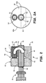
- the first arm 38 extends from the connection portion 36 and receives the fastener 32 and the helicoil 34 therein, in particular in the first aperture 44 that extends through first arm 38.
- the wall that defines the first aperture 44 has a plurality of threads.
- the first aperture 44 is adapted to receive and engage the helicoil 34, which includes a mating thread.
- the helicoil 34 is hollow and includes a thread on an internal portion.
- the hollow helicoil 34 is adapted to receive and engage with the fastener 32, which includes a mating external thread. In the locked position shown in FIG. 2 , the fastener 32 extends through the first aperture 44 and across the notch 42 to abut the second arm 40.
- the locking torsion force 52 is distributed over a plurality of threads of the rod 50.
- the distributed force allows for a finer thread to be used, which results in more precise adjustment of the adjustment mechanism 26 and easier calibration of the LVDT 14 ( FIG. 1 ).
- the application of the locking torsion force 52 by the locking mechanism 16 has minimal to no impact on the positioning of the adjustment mechanism 26. Thus, personnel do not have to undergo a repetitious trial and error process to calibrate the LVDT 14.
- the fastener 32 is backed out of abutment with the second arm 40. With the fastener 32 backed out of abutment, the rod 50 is then free to be moved by tooling relative to collar 30 to change the position of the adjustment mechanism 26 relative to the stationary portion 28 of the LVDT 14 ( FIG. 1 ).
Landscapes
- Engineering & Computer Science (AREA)
- General Engineering & Computer Science (AREA)
- Mechanical Engineering (AREA)
- Chemical & Material Sciences (AREA)
- Combustion & Propulsion (AREA)
- Control Of Turbines (AREA)
- Fuel-Injection Apparatus (AREA)
Applications Claiming Priority (1)
| Application Number | Priority Date | Filing Date | Title |
|---|---|---|---|
| US13/891,558 US20140332703A1 (en) | 2013-05-10 | 2013-05-10 | Adjustment and locking mechanisms |
Publications (1)
| Publication Number | Publication Date |
|---|---|
| EP2811175A1 true EP2811175A1 (de) | 2014-12-10 |
Family
ID=50685781
Family Applications (1)
| Application Number | Title | Priority Date | Filing Date |
|---|---|---|---|
| EP14167695.7A Withdrawn EP2811175A1 (de) | 2013-05-10 | 2014-05-09 | Einstellungs- und Verriegelungsmechanismus |
Country Status (2)
| Country | Link |
|---|---|
| US (1) | US20140332703A1 (de) |
| EP (1) | EP2811175A1 (de) |
Families Citing this family (3)
| Publication number | Priority date | Publication date | Assignee | Title |
|---|---|---|---|---|
| FR3019583B1 (fr) * | 2014-04-08 | 2019-09-13 | Safran Aircraft Engines | Isolation d'un reservoir de fluide combustible relativement a une partie aval de systeme d'alimentation pour turbomachine en cas d'incendie |
| US9416894B2 (en) * | 2014-06-25 | 2016-08-16 | Leo William Abel | Locking mechanism with visible status indication |
| US10858901B1 (en) * | 2018-02-20 | 2020-12-08 | Shazam Rahim | Remotely operated connecting assembly and method |
Citations (6)
| Publication number | Priority date | Publication date | Assignee | Title |
|---|---|---|---|---|
| US2863210A (en) * | 1952-07-30 | 1958-12-09 | Mccrosky Tool Corp | Locking devices |
| JPS51114550A (en) * | 1975-04-01 | 1976-10-08 | Mitachi Onkyo Seisakusho:Kk | Method for fixing adjusting nut, and lock nut |
| US5448882A (en) | 1993-12-14 | 1995-09-12 | United Technologies Corporation | Fuel metering system |
| US6321527B1 (en) | 1998-01-08 | 2001-11-27 | Hamilton Sundstrand Corporation | Bi-level fuel pressurizing system |
| US6401446B1 (en) | 2000-06-23 | 2002-06-11 | Hamilton Sundstrand Corporation | Valve apparatus for providing shutoff and overspeed protection in a gas turbine fuel system |
| US6682016B1 (en) | 2002-09-05 | 2004-01-27 | Hamilton Sundstrand | Thermal management valve with drop-tight shutoff of return to tank |
Family Cites Families (2)
| Publication number | Priority date | Publication date | Assignee | Title |
|---|---|---|---|---|
| US4635441A (en) * | 1985-05-07 | 1987-01-13 | Sundstrand Corporation | Power drive unit and control system therefor |
| US7654093B2 (en) * | 2005-09-26 | 2010-02-02 | Pratt & Whitney Canada Corp. | Method of adjusting a triggering clearance and a trigger |
-
2013
- 2013-05-10 US US13/891,558 patent/US20140332703A1/en not_active Abandoned
-
2014
- 2014-05-09 EP EP14167695.7A patent/EP2811175A1/de not_active Withdrawn
Patent Citations (6)
| Publication number | Priority date | Publication date | Assignee | Title |
|---|---|---|---|---|
| US2863210A (en) * | 1952-07-30 | 1958-12-09 | Mccrosky Tool Corp | Locking devices |
| JPS51114550A (en) * | 1975-04-01 | 1976-10-08 | Mitachi Onkyo Seisakusho:Kk | Method for fixing adjusting nut, and lock nut |
| US5448882A (en) | 1993-12-14 | 1995-09-12 | United Technologies Corporation | Fuel metering system |
| US6321527B1 (en) | 1998-01-08 | 2001-11-27 | Hamilton Sundstrand Corporation | Bi-level fuel pressurizing system |
| US6401446B1 (en) | 2000-06-23 | 2002-06-11 | Hamilton Sundstrand Corporation | Valve apparatus for providing shutoff and overspeed protection in a gas turbine fuel system |
| US6682016B1 (en) | 2002-09-05 | 2004-01-27 | Hamilton Sundstrand | Thermal management valve with drop-tight shutoff of return to tank |
Also Published As
| Publication number | Publication date |
|---|---|
| US20140332703A1 (en) | 2014-11-13 |
Similar Documents
| Publication | Publication Date | Title |
|---|---|---|
| US9567784B2 (en) | Hook latch fitted with a positioning device and a method for assembling such a latch | |
| EP2811175A1 (de) | Einstellungs- und Verriegelungsmechanismus | |
| EP2686138B1 (de) | Verfahren zum drehen eines drehbaren teils | |
| EP0703362B1 (de) | Verfahren zur Einstellung und Überprüfung des Durchflusses bei Ventilen | |
| DE2423300B2 (de) | Kraftbetätigtes Werkzeug mit ausgangsdrehmomentabhängiger selbsttätiger Abschaltung | |
| EP2209998B1 (de) | Vorgesteuerter wegeschieber, insbesondere zur steuerung eines stellzylinders einer turbomaschine | |
| DE69214068T2 (de) | Stellantrieb für eine Raketensteuerfläche | |
| EP3273015B1 (de) | Kalibriervorrichtung zur durchführung eines demontageverfahrens für gasturbinen | |
| DE10230004A1 (de) | Durchflussratensteuerventil | |
| EP3466806A1 (de) | Steuervorrichtung für einen hydraulischen verstellpropeller sowie verstellpropeller-einheit mit einer derartigen steuervorrichtung | |
| US20150096641A1 (en) | Flow regulating apparatus | |
| JP2008286794A (ja) | 圧力指示装置 | |
| DE1915824C3 (de) | Regelanlage für Gasturbinentriebwerke | |
| DE3044540A1 (de) | Druckuebertrager | |
| EP3492786B1 (de) | Druckentlastungsventil | |
| DE2653336C2 (de) | Vorrichtung zum Erfassen des Druckes in einer Strömungskammer | |
| SE508571C2 (sv) | Borrverktyg med ultraprecision för submikront bruk och förinställningssystem | |
| DE202022106934U1 (de) | Vorrichtung für eine Gasturbine | |
| US4177681A (en) | Apparatus for adjusting and locking a linear actuator | |
| DE69929650T2 (de) | Druckregler | |
| EP3220023B1 (de) | Wegeventil | |
| US3379167A (en) | Dispensing device | |
| EP3006163A1 (de) | Werkzeug zum setzen des zündkerzenelektrodenabstands | |
| DE2643607B1 (de) | Vorrichtung zur uebertragung und ermittlung des wahren schaufelanstellwinkels verstellbarer leitschaufeln einer turbomaschine, insbesondere eines gasturbinentriebwerks | |
| DE3830804C2 (de) |
Legal Events
| Date | Code | Title | Description |
|---|---|---|---|
| PUAI | Public reference made under article 153(3) epc to a published international application that has entered the european phase |
Free format text: ORIGINAL CODE: 0009012 |
|
| 17P | Request for examination filed |
Effective date: 20140509 |
|
| AK | Designated contracting states |
Kind code of ref document: A1 Designated state(s): AL AT BE BG CH CY CZ DE DK EE ES FI FR GB GR HR HU IE IS IT LI LT LU LV MC MK MT NL NO PL PT RO RS SE SI SK SM TR |
|
| AX | Request for extension of the european patent |
Extension state: BA ME |
|
| STAA | Information on the status of an ep patent application or granted ep patent |
Free format text: STATUS: THE APPLICATION IS DEEMED TO BE WITHDRAWN |
|
| 18D | Application deemed to be withdrawn |
Effective date: 20150611 |