EP2811198B1 - Ringförmige feder und verfahren zur herstellung davon - Google Patents
Ringförmige feder und verfahren zur herstellung davon Download PDFInfo
- Publication number
- EP2811198B1 EP2811198B1 EP13742940.3A EP13742940A EP2811198B1 EP 2811198 B1 EP2811198 B1 EP 2811198B1 EP 13742940 A EP13742940 A EP 13742940A EP 2811198 B1 EP2811198 B1 EP 2811198B1
- Authority
- EP
- European Patent Office
- Prior art keywords
- mass
- raw material
- ring
- welded
- welding
- Prior art date
- Legal status (The legal status is an assumption and is not a legal conclusion. Google has not performed a legal analysis and makes no representation as to the accuracy of the status listed.)
- Active
Links
Images
Classifications
-
- F—MECHANICAL ENGINEERING; LIGHTING; HEATING; WEAPONS; BLASTING
- F16—ENGINEERING ELEMENTS AND UNITS; GENERAL MEASURES FOR PRODUCING AND MAINTAINING EFFECTIVE FUNCTIONING OF MACHINES OR INSTALLATIONS; THERMAL INSULATION IN GENERAL
- F16F—SPRINGS; SHOCK-ABSORBERS; MEANS FOR DAMPING VIBRATION
- F16F1/00—Springs
- F16F1/02—Springs made of steel or other material having low internal friction; Wound, torsion, leaf, cup, ring or the like springs, the material of the spring not being relevant
- F16F1/34—Ring springs, i.e. annular bodies deformed radially due to axial load
-
- B—PERFORMING OPERATIONS; TRANSPORTING
- B21—MECHANICAL METAL-WORKING WITHOUT ESSENTIALLY REMOVING MATERIAL; PUNCHING METAL
- B21D—WORKING OR PROCESSING OF SHEET METAL OR METAL TUBES, RODS OR PROFILES WITHOUT ESSENTIALLY REMOVING MATERIAL; PUNCHING METAL
- B21D11/00—Bending not restricted to forms of material mentioned in only one of groups B21D5/00, B21D7/00, B21D9/00; Bending not provided for in groups B21D5/00 - B21D9/00; Twisting
- B21D11/10—Bending specially adapted to produce specific articles, e.g. leaf springs
-
- B—PERFORMING OPERATIONS; TRANSPORTING
- B21—MECHANICAL METAL-WORKING WITHOUT ESSENTIALLY REMOVING MATERIAL; PUNCHING METAL
- B21F—WORKING OR PROCESSING OF METAL WIRE
- B21F35/00—Making springs from wire
- B21F35/04—Making flat springs, e.g. sinus springs
-
- B—PERFORMING OPERATIONS; TRANSPORTING
- B23—MACHINE TOOLS; METAL-WORKING NOT OTHERWISE PROVIDED FOR
- B23K—SOLDERING OR UNSOLDERING; WELDING; CLADDING OR PLATING BY SOLDERING OR WELDING; CUTTING BY APPLYING HEAT LOCALLY, e.g. FLAME CUTTING; WORKING BY LASER BEAM
- B23K26/00—Working by laser beam, e.g. welding, cutting or boring
- B23K26/20—Bonding
- B23K26/21—Bonding by welding
- B23K26/24—Seam welding
- B23K26/26—Seam welding of rectilinear seams
-
- B—PERFORMING OPERATIONS; TRANSPORTING
- B23—MACHINE TOOLS; METAL-WORKING NOT OTHERWISE PROVIDED FOR
- B23K—SOLDERING OR UNSOLDERING; WELDING; CLADDING OR PLATING BY SOLDERING OR WELDING; CUTTING BY APPLYING HEAT LOCALLY, e.g. FLAME CUTTING; WORKING BY LASER BEAM
- B23K26/00—Working by laser beam, e.g. welding, cutting or boring
- B23K26/20—Bonding
- B23K26/32—Bonding taking account of the properties of the material involved
-
- B—PERFORMING OPERATIONS; TRANSPORTING
- B23—MACHINE TOOLS; METAL-WORKING NOT OTHERWISE PROVIDED FOR
- B23P—METAL-WORKING NOT OTHERWISE PROVIDED FOR; COMBINED OPERATIONS; UNIVERSAL MACHINE TOOLS
- B23P15/00—Making specific metal objects by operations not covered by a single other subclass or a group in this subclass
-
- C—CHEMISTRY; METALLURGY
- C21—METALLURGY OF IRON
- C21D—MODIFYING THE PHYSICAL STRUCTURE OF FERROUS METALS; GENERAL DEVICES FOR HEAT TREATMENT OF FERROUS OR NON-FERROUS METALS OR ALLOYS; MAKING METAL MALLEABLE, e.g. BY DECARBURISATION OR TEMPERING
- C21D6/00—Heat treatment of ferrous alloys
- C21D6/008—Heat treatment of ferrous alloys containing Si
-
- C—CHEMISTRY; METALLURGY
- C21—METALLURGY OF IRON
- C21D—MODIFYING THE PHYSICAL STRUCTURE OF FERROUS METALS; GENERAL DEVICES FOR HEAT TREATMENT OF FERROUS OR NON-FERROUS METALS OR ALLOYS; MAKING METAL MALLEABLE, e.g. BY DECARBURISATION OR TEMPERING
- C21D9/00—Heat treatment, e.g. annealing, hardening, quenching or tempering, adapted for particular articles; Furnaces therefor
- C21D9/02—Heat treatment, e.g. annealing, hardening, quenching or tempering, adapted for particular articles; Furnaces therefor for springs
-
- C—CHEMISTRY; METALLURGY
- C22—METALLURGY; FERROUS OR NON-FERROUS ALLOYS; TREATMENT OF ALLOYS OR NON-FERROUS METALS
- C22C—ALLOYS
- C22C38/00—Ferrous alloys, e.g. steel alloys
-
- C—CHEMISTRY; METALLURGY
- C22—METALLURGY; FERROUS OR NON-FERROUS ALLOYS; TREATMENT OF ALLOYS OR NON-FERROUS METALS
- C22C—ALLOYS
- C22C38/00—Ferrous alloys, e.g. steel alloys
- C22C38/02—Ferrous alloys, e.g. steel alloys containing silicon
-
- C—CHEMISTRY; METALLURGY
- C22—METALLURGY; FERROUS OR NON-FERROUS ALLOYS; TREATMENT OF ALLOYS OR NON-FERROUS METALS
- C22C—ALLOYS
- C22C38/00—Ferrous alloys, e.g. steel alloys
- C22C38/04—Ferrous alloys, e.g. steel alloys containing manganese
-
- C—CHEMISTRY; METALLURGY
- C22—METALLURGY; FERROUS OR NON-FERROUS ALLOYS; TREATMENT OF ALLOYS OR NON-FERROUS METALS
- C22C—ALLOYS
- C22C38/00—Ferrous alloys, e.g. steel alloys
- C22C38/08—Ferrous alloys, e.g. steel alloys containing nickel
-
- C—CHEMISTRY; METALLURGY
- C22—METALLURGY; FERROUS OR NON-FERROUS ALLOYS; TREATMENT OF ALLOYS OR NON-FERROUS METALS
- C22C—ALLOYS
- C22C38/00—Ferrous alloys, e.g. steel alloys
- C22C38/18—Ferrous alloys, e.g. steel alloys containing chromium
-
- C—CHEMISTRY; METALLURGY
- C22—METALLURGY; FERROUS OR NON-FERROUS ALLOYS; TREATMENT OF ALLOYS OR NON-FERROUS METALS
- C22C—ALLOYS
- C22C38/00—Ferrous alloys, e.g. steel alloys
- C22C38/18—Ferrous alloys, e.g. steel alloys containing chromium
- C22C38/34—Ferrous alloys, e.g. steel alloys containing chromium with more than 1.5% by weight of silicon
-
- C—CHEMISTRY; METALLURGY
- C22—METALLURGY; FERROUS OR NON-FERROUS ALLOYS; TREATMENT OF ALLOYS OR NON-FERROUS METALS
- C22C—ALLOYS
- C22C38/00—Ferrous alloys, e.g. steel alloys
- C22C38/18—Ferrous alloys, e.g. steel alloys containing chromium
- C22C38/38—Ferrous alloys, e.g. steel alloys containing chromium with more than 1.5% by weight of manganese
-
- F—MECHANICAL ENGINEERING; LIGHTING; HEATING; WEAPONS; BLASTING
- F16—ENGINEERING ELEMENTS AND UNITS; GENERAL MEASURES FOR PRODUCING AND MAINTAINING EFFECTIVE FUNCTIONING OF MACHINES OR INSTALLATIONS; THERMAL INSULATION IN GENERAL
- F16F—SPRINGS; SHOCK-ABSORBERS; MEANS FOR DAMPING VIBRATION
- F16F1/00—Springs
- F16F1/02—Springs made of steel or other material having low internal friction; Wound, torsion, leaf, cup, ring or the like springs, the material of the spring not being relevant
- F16F1/025—Springs made of steel or other material having low internal friction; Wound, torsion, leaf, cup, ring or the like springs, the material of the spring not being relevant characterised by having a particular shape
- F16F1/027—Planar, e.g. in sheet form; leaf springs
-
- B—PERFORMING OPERATIONS; TRANSPORTING
- B21—MECHANICAL METAL-WORKING WITHOUT ESSENTIALLY REMOVING MATERIAL; PUNCHING METAL
- B21D—WORKING OR PROCESSING OF SHEET METAL OR METAL TUBES, RODS OR PROFILES WITHOUT ESSENTIALLY REMOVING MATERIAL; PUNCHING METAL
- B21D53/00—Making other particular articles
- B21D53/16—Making other particular articles rings, e.g. barrel hoops
-
- B—PERFORMING OPERATIONS; TRANSPORTING
- B23—MACHINE TOOLS; METAL-WORKING NOT OTHERWISE PROVIDED FOR
- B23K—SOLDERING OR UNSOLDERING; WELDING; CLADDING OR PLATING BY SOLDERING OR WELDING; CUTTING BY APPLYING HEAT LOCALLY, e.g. FLAME CUTTING; WORKING BY LASER BEAM
- B23K2101/00—Articles made by soldering, welding or cutting
- B23K2101/32—Wires
-
- B—PERFORMING OPERATIONS; TRANSPORTING
- B23—MACHINE TOOLS; METAL-WORKING NOT OTHERWISE PROVIDED FOR
- B23K—SOLDERING OR UNSOLDERING; WELDING; CLADDING OR PLATING BY SOLDERING OR WELDING; CUTTING BY APPLYING HEAT LOCALLY, e.g. FLAME CUTTING; WORKING BY LASER BEAM
- B23K2103/00—Materials to be soldered, welded or cut
- B23K2103/02—Iron or ferrous alloys
- B23K2103/04—Steel or steel alloys
-
- B—PERFORMING OPERATIONS; TRANSPORTING
- B23—MACHINE TOOLS; METAL-WORKING NOT OTHERWISE PROVIDED FOR
- B23K—SOLDERING OR UNSOLDERING; WELDING; CLADDING OR PLATING BY SOLDERING OR WELDING; CUTTING BY APPLYING HEAT LOCALLY, e.g. FLAME CUTTING; WORKING BY LASER BEAM
- B23K2103/00—Materials to be soldered, welded or cut
- B23K2103/50—Inorganic materials other than metals or composite materials
-
- F—MECHANICAL ENGINEERING; LIGHTING; HEATING; WEAPONS; BLASTING
- F16—ENGINEERING ELEMENTS AND UNITS; GENERAL MEASURES FOR PRODUCING AND MAINTAINING EFFECTIVE FUNCTIONING OF MACHINES OR INSTALLATIONS; THERMAL INSULATION IN GENERAL
- F16F—SPRINGS; SHOCK-ABSORBERS; MEANS FOR DAMPING VIBRATION
- F16F2226/00—Manufacturing; Treatments
- F16F2226/04—Assembly or fixing methods; methods to form or fashion parts
- F16F2226/048—Welding
Definitions
- the present invention relates to a ring spring, such as a disk spring or a wave spring, and relates to a method for producing the same.
- the ring spring such as a disk spring and a wave spring, has been used for absorbing shocks that occur during engaging a clutch in a clutch device in transportation equipment, for example.
- a conventional method for producing the ring spring a blank having approximately a ring shape has been punched out of a tabular material by pressing processing; however, in this method, the yield ratio of the material was poor.
- a method to improve the yield ratio of the material a method is known in which edge parts of material formed in a ring shape by bending formation are welded (see Japanese Unexamined Patent Application Publications Nos. Hei 06 (1994)-106277 and 2001-225112 ).
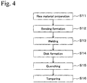
- a process shown in Fig. 4 is employed, for example.
- material is prepared (step S11), the material is formed in approximately a ring shape by bending formation (step S12), and the edge parts of the approximately ring shape material are mutually welded (step S13).
- step S13 ring material having no edge can be obtained.
- the ring material is processed to a disk shape (approximately cone shape) by cold forming (disk forming) so as to obtain disk spring material (step S14). Subsequently, by performing quenching and tempering of the disk spring material (steps S15 and S16) so as to obtain the disk spring.
- the welded part of the material becomes a welded metal part, and a circumferential part thereof becomes a welded heat-affected zone that is affected by heating during welding.
- a hardened region is formed at the welded metal part and a softened region is formed at the welded heat-affected zone, in order to keep strength necessary as a disk spring, it is necessary that quenching and tempering be performed on the disk spring material after cold forming.
- quenching and tempering are required and thereby increase the number of processes, production cost may be increased and the product may be expensive.
- US 2011/0006467 A1 discloses a disc spring formed out of a metal strip, which is bent to form a ring and having end parts, which are connected by means of electron beam welding.
- US 6,206,984 B1 discloses a non-heat treated wire or bar steel for springs, which have in its as-rolled state a tensile strength of 120-150 kgf/mm 2 and a bending breakage rate no higher than 15%.
- the composition of this wire or bar steel comprises Nb: 0.005-0.15 wt%, Ti: 0.01-0.1 wt%, B: 0.0005-0.01% wt%, Cr: 1.02-1.8 wt%, as well as more than 0% aluminum and Fe.
- an object of the present invention is to provide an inexpensive ring spring having high strength and a method for producing the same.
- the ring spring of the present invention is a ring spring which is formed to have no edge by welding both edges of raw material, and has a welded metal part which is formed at interface part of the both edges of the raw material, and a welded heat-affected zone which is formed circumference of the welded metal part and which is heated by welding, and the ring spring has a tensile strength of 1000 MPa or more and a composition as defined in the appended claim 1.
- the ring spring of the present invention is obtained by welding the two edge parts of the raw material, the ring spring has the welded metal part and the welded heat-affected zone.
- the ring spring has tensile strength of 1000 MPa or more in a condition in which it has the welded metal part and the welded heat-affected zone, which is a sufficient tensile strength for a disk spring and a wave spring for example, and therefore, quenching and tempering are not necessary.
- the ring spring of the present invention With respect to chemical components, the content of C should be decreased since a larger content of C may cause formation of a quenching hardened layer and decrease of toughness. However, in the case in which content of C is reduced, since strength may be decreased, it may be necessary to increase strength by action of solid-solution strengthening and miniaturization of crystal particles or the like, brought by adding an element other than C.
- the chemical components of the raw material consist of C: 0.10 to 0.30 mass%, Si: 0.50 to 2.10 mass%, Cr: 0.50 to 1.50 mass%, Mn: 1.0 to 2.0 mass%, P: 0.025 mass% or less, S: 0.025 mass% or less, Fe as a remainder and inevitable impurities.
- C is an important element to maintain strength of the welded part.
- Strength of the welded part may be insufficient in a case in which content of C is less than 0.10 %.
- content of C is more than 0.30 %, a hardened structure such as martensite or the like is increased, a quenched hardened layer is formed, and toughness is decreased. Therefore, in order to improve strength of the welded part and toughness, content of C is set within 0.10 to 0.30 %.
- Si is an important element to maintain strength of the welded part as an element to strengthen solid solution.
- Strength of the welded part may be insufficient in a case in which content of Si is less than 0.50 %.
- content of Si is more than 2.10 %, the effect of maintaining strength may be saturated and properties of welding may be degraded. Therefore, in order to improve strength of the welded part and property of welding, content of Si is set within 0.50 to 2.10 %.
- Cr is an effective element to increase strength of the welded part.
- Strength of the welded part may be insufficient in a case in which the content of C is less than 0.50 %.
- the content of C is more than 1.50 %, toughness is decreased. Therefore, in order to improve strength of the welded part and toughness, the content of Cr is set within 0.50 to 1.50 %.
- Mn is an effective element to prevent hot brittleness by S, in addition to improve strength as an element to strengthen a solid solution. Strength may be insufficient in a case in which the content of Mn is less than 1.0 %. On the other hand, in a case in which the content of Mn is more than 2.0 %, workability is decreased. Therefore, in order to improve strength and workability, the content of Mn is set within 1.0 to 2.0 %.
- the content of P be as low as possible, since a high content of P may cause deterioration of workability and welding property.
- the P content of 0.025 % or less can be acceptable in order to maintain workability and welding property in a ring spring.
- the content of S be as low as possible, since a high content of S may cause deterioration of ductility.
- the S content of 0.025 % or less can be acceptable in order to maintain ductility in a ring spring.
- At least one of Ni, Mo, Ti, V and Nb can be added.
- a steel material having carbon equivalent Ceq shown by below formula (1) of 0.5 to 0.75 mass% and hardness of 350 HV or more can be used, and the steel material can contain C: 0.30 mass% or less.
- "[ ]” means content (mass%) of each element.
- the carbon equivalent Ceq is set from 0.5 to 0.75 mass%. Furthermore, by limiting the hardness of the raw material (master material) at 350 HV or more, strength that is required for a material after welding can be effectively obtained.
- the welding start part of the welded metal part be formed at one of an outer circumferential part or inner circumferential part having higher tensile stress.
- a ring spring for example, a disk spring having a disk shape or a wave spring having a wavy shape consisting of a mountain part and a valley part can be mentioned.
- the wave spring it is desirable that the mountain part and the valley part, at which stress generation peaks, be formed at a position different from the welded metal part.
- a method for producing ring spring of the present invention includes steps of: a bending forming process in which raw material is formed in approximately a ring shape by bending forming, a welding process in which edge parts of the raw material of the approximately ring shape are mutually welded so as to obtain a raw material ring having no edge, in which in the welding process, a welded metal part is formed at an interface of the two edge parts of the raw material, and welded heat-affected zone which is heated by welding is formed around the welded metal part, and in which the ring spring has tensile strength of 1000 MPa or more and a composition as defined in the appended claim 1.
- the product can be strengthened and the cost can be reduced at the same time.
- 1A, 1B Raw material ring having no edge
- 2 wave spring
- 11 outer circumferential part
- 12 inner circumferential part
- 13 welded metal part
- 21 convex part
- 31 mountain part
- 32 valley part.
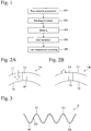
- Fig. 1 is the flow chart diagram showing the production processes of the method for producing the ring spring of one Embodiment of the present invention.
- raw material preparation step S1
- bending formation step S2
- welding step S3
- disk formation step S4
- low-temperature annealing step S5
- the raw material is prepared (step S1).
- a material that has tensile strength of 1000 MPa or more in a condition in which the ring spring obtained from the raw material has a welded metal part and a welded heat-affected zone is used.
- the raw material consists of C: 0.10 to 0.30 mass%, Si: 0.50 to 2.10 mass%, Cr: 0.50 to 1.50 mass%, Mn: 1.0 to 2.0 mass%, P: 0.025 mass% or less, S: 0.025 mass% or less, Fe as the remainder and inevitable impurities.
- C, Cr, and Mn more desirable content amounts are C: 0.15 to 0.25 mass%, Cr: 0.8 to 1.1 mass%, and Mn: 1.3 to 1.7 mass%.
- the raw material can be obtained for example, a material which is austenitized and then rapid-cooled, a material which is austenitized and then austempering-treated, or a material which is austenitized and then patenting-treated, is processed by wire drawing.
- a structure of the raw material wire material, tabular material, strip material or the like is used. In this case, kinds of structure such as elongated material, hoop material, coil material, and fixed scale material can be used.
- As a cross-sectional shape of the raw material it is not limited only to a square cross section, and other cross section such as trapezoid, ellipse or the like can be employed.
- the raw material ring is obtained (step S2).
- the raw material can be formed as a raw material ring having a disk shape (approximately cone shape) by performing disk formation and bending formation at the same time.
- a raw material ring having wavy shape consisting of mountain part and valley part can be made. In these cases, following disk formation or wavy shape formation of step S4 can be omitted.
- the raw material ring having no edge has the welded metal part that is formed at an interface of two edge parts of the raw material, and the welded heat-affected zone that is formed around the welded metal part and is heated during welding.
- Various methods can be employed as the welding method, and it is not limited in particular, but a laser welding is desirable. In the laser welding, since the emission spot is small, formation of the welded heat-affected zone can be reduced. A convex bead formed on the welded metal part can be removed if necessary.
- the disk spring In a case in which the disk spring is produced, for example, at a concave surface side in which tensile stress occurs during elastic deformation in order to lower the height along an axis line direction, it can be designed so that tensile stress of the outer circumferential part is higher than that of the inner circumferential part, or so that tensile stress of the inner circumferential part is higher than that of the outer circumferential part.
- the welding direction be determined as follows in view of the possibility of the occurrence of shrinkage by welding.
- Fig. 2A shows a raw material ring 1A that is used as a raw material of a disk spring in which tensile stress of outer circumferential part 11 is set higher than that of inner circumferential part 12.
- a direction arrow line direction
- welded metal part 13 is formed at facing part.
- shrinkage occurs at the inner circumferential part 12 in which tensile stress is low, thereby forming concave part 21, and the concave part is not formed at the outer circumferential part 11 having high tensile stress.
- FIG. 2B shows a raw material ring 1B that is used as a raw material of a disk spring in which tensile stress of inner circumferential part 12 is set higher than that of outer circumferential part 11.
- the raw material ring 1B when welding is performed along a direction (arrow line direction) from the inner circumferential part 12 to the outer circumferential part 11, shrinkage occurs at the outer circumferential part 11 in which tensile stress is low, thereby forming concave part 21, and concave part is not formed at the inner circumferential part 12 having high tensile stress. In this way, it is desirable that welding be performed from a circumferential part having high tensile stress to a circumferential part having low tensile stress.
- the approximately cone disk spring (ring spring) is obtained (step S4). Practically, by flattening the raw material ring having no edge into an approximately oblate condition having a certain thickness by hot or cold press forming, the approximately cone disk spring is obtained.
- the wave spring can be obtained by performing wavy formation by cold or hot pressing, instead of by disk formation. For example, in a case in which wave spring 2 shown in Fig. 3 is produced, it is desirable that mountain part 31 and valley part 32 be formed at a position different from the welded metal part 33.
- strain can be removed (step S5) by performing low-temperature annealing on the ring spring (disk spring or wave spring).
- the low-temperature annealing is performed at 250 °C for 60 minutes, for example. It should be noted that temperature or time for heating can be controlled, if necessary. In the case in which the ring spring is used in hot condition, low-temperature annealing is desirable since deformation can be controlled.
- the ring spring produced in this Embodiment is obtained by welding both edge parts of the raw material, and the ring spring has the welded metal part and the welded heat-affected zone.
- tensile strength is 1000 MPa or more in the condition in which the ring spring has the welded metal part and the welded heat-affected zone, being of sufficient tensile strength as a disk spring and a wave spring, quenching and tempering are not necessary. Therefore, production cost can be reduced. As a result, price of the product can be reduced. Furthermore, since quenching and tempering are not performed, as a result of preventing the product from being deformed, dimensional accuracy of the product can be improved.
- the present invention was explained as above by way of an Embodiment, but the present invention is not limited to the above Embodiment, and variations are possible.
- shot peening can be performed on the ring spring to obtain compressive residual stress and barrel polishing can be performed on the ring spring to improve surface cleanliness, if necessary.
- multiple convex parts can be arranged on an inner or outer circumferential part of the main body of the disk spring.
- a single disk spring can be used, or multiple disk springs can be used arranged in series or in parallel.
- disk springs can be welded in order to prevent misalignment of positions.
- disk springs were produced using kinds of raw materials each having chemical composition, carbon equivalent Ceq, (unit: mass%), hardness (unit: HV), and tensile strength (TS before welding, unit: MPa) shown in Table 1. Durability test of each disk spring was performed so that it could be determined whether it passed or failed the test.
- raw material width: 7 mm, thickness: 1.5 mm
- raw material rings outer diameter: 100 mm
- both edge parts of the raw material were brought into facing condition.
- the facing part was welded by laser so as to obtain a raw material ring having no edge, and a disk spring (free height: 2.5 mm) was produced by performing cold disk formation on the raw material ring.
- Conditions of production of the samples such as bending formation, laser welding, and disk formation were all the same except that chemical composition or like of the raw material were different, as shown in Table 1.
- Examples B, C, D, J, and K of the present invention that were produced using raw material having chemical composition, carbon equivalent, hardness and TS before welding within the range of the present invention as shown in Table 1 were not broken during the durability test and exhibited tensile strength of 1000 MPa or more, as shown in Table 2.
- Comparative Examples A, E, F, G, H, and I were broken during the durability test and exhibited tensile strength after welding of less than 1000 MPa.
- Comparative Examples A and G have content amount of C of less than 0.3 mass%; however, they were considered to be broken at the welded heat-affected part because hardness of the raw material (master material) was low, being less than 350 HV, and had originally low strength, and further decreased in strength by influence of heat.
- the ring spring that is produced using raw material having the chemical composition, carbon equivalent, hardness and tensile strength before welding within the range of the present invention exhibits high strength with a tensile strength of 1000 MPa or more even without performing quenching.
Landscapes
- Engineering & Computer Science (AREA)
- Chemical & Material Sciences (AREA)
- Mechanical Engineering (AREA)
- Materials Engineering (AREA)
- Metallurgy (AREA)
- Organic Chemistry (AREA)
- Physics & Mathematics (AREA)
- Optics & Photonics (AREA)
- General Engineering & Computer Science (AREA)
- Plasma & Fusion (AREA)
- Crystallography & Structural Chemistry (AREA)
- Thermal Sciences (AREA)
- Springs (AREA)
- Heat Treatment Of Articles (AREA)
Claims (5)
- Ringfeder, die ausgebildet ist, um keine Kante durch das Verschweißen zweier Kanten eines Rohmaterials aufzuweisen, enthaltend:einen geschweißten Metallabschnitt, der an einer Grenzfläche von zwei Kanten des Rohmaterials ausgebildet ist, undeinen geschweißten, wärmebeeinflussten Bereich, der am Umfang des geschweißten Metallabschnitts ausgebildet ist und durch Schweißen erhitzt wird,wobei die Zugfestigkeit 1000 MPa oder mehr beträgt,dadurch gekennzeichnet, dass das Rohmaterial aus C: 0,10 bis 0,30 Massen-%, Si: 0,50 bis 2,10 Massen-%, Cr: 0,50 bis 1,50 Massen-%, Mn: 1,0 bis 2,0 Massen-%, P: 0,025 Massen-% oder weniger, S: 0,025 Massen-% oder weniger, Fe als Rest und unvermeidbaren Verunreinigungen besteht und ein Kohlenstoffäquivalent Ceq, nachstehend ausgedrückt durch Formel (1), von 0,5 bis 0,75 Massen-% und eine Härte von 350 HV oder mehr aufweist, wobei die eckigen Klammern die Massen-% kennzeichnen, und wobei

- Ringfeder nach Anspruch 1, wobei ein Schweißstartabschnitt des geschweißten Metallabschnitts an entweder einem äußeren Umfangsabschnitt oder einem inneren Umfangsabschnitt mit einer höheren Zugfestigkeit als der andere ausgebildet ist.
- Ringfeder nach Anspruch 1 oder 2, wobei die Ringfeder eine Scheibenfeder mit einer Scheibenform oder eine Wellenfeder mit einer welligen Form bestehend aus einem Berg und einem Tal ist.
- Ringfeder nach Anspruch 3, wobei der Berg und das Tal an einer Position, die verschieden von dem geschweißten Metallabschnitt ist, ausgebildet sind.
- Verfahren zum Herstellen einer Ringfeder, wobei das Verfahren die Schritte enthält:einen Biegeformvorgang, in welchem das Rohmaterial in einer annähernden Ringform durch Biegeformen ausgebildet wird,einen Schweißvorgang, in welchem Kantenabschnitte des Rohmaterials der annähernden Ringform wechselseitig verschweißt werden, um einen Rohmaterialring ohne Kanten zu erhalten,wobei in dem Schweißvorgang ein geschweißter Metallabschnitt an einer Grenzfläche der zwei Kantenabschnitte des Rohmaterials ausgebildet wird, und ein geschweißter, wärmebeeinflusster Bereich, der durch Schweißen erhitzt wird, um den geschweißten Metallabschnitt herum ausgebildet wird, undwobei Ringfeder eine Zugfestigkeit von 1000 MPa oder mehr aufweist,dadurch gekennzeichnet, dass das Rohmaterial aus C: 0,10 bis 0,30 Massen-%, Si: 0,50 bis 2,10 Massen-%, Cr: 0,50 bis 1,50 Massen-%, Mn: 1,0 bis 2,0 Massen-%, P: 0,025 Massen-% oder weniger, S: 0,025 Massen-% oder weniger, Fe als Rest und unvermeidbaren Verunreinigungen besteht und ein Kohlenstoffäquivalent Ceq, nachstehend ausgedrückt durch Formel (1), von 0,5 bis 0,75 Massen-% und eine Härte von 350 HV oder mehr aufweist, wobei die eckigen Klammern die Massen-% kennzeichnen, und wobei

Applications Claiming Priority (2)
| Application Number | Priority Date | Filing Date | Title |
|---|---|---|---|
| JP2012019046 | 2012-01-31 | ||
| PCT/JP2013/052080 WO2013115266A1 (ja) | 2012-01-31 | 2013-01-30 | リング状ばねおよびその製造方法 |
Publications (3)
| Publication Number | Publication Date |
|---|---|
| EP2811198A1 EP2811198A1 (de) | 2014-12-10 |
| EP2811198A4 EP2811198A4 (de) | 2016-01-06 |
| EP2811198B1 true EP2811198B1 (de) | 2019-03-20 |
Family
ID=48905298
Family Applications (1)
| Application Number | Title | Priority Date | Filing Date |
|---|---|---|---|
| EP13742940.3A Active EP2811198B1 (de) | 2012-01-31 | 2013-01-30 | Ringförmige feder und verfahren zur herstellung davon |
Country Status (5)
| Country | Link |
|---|---|
| US (1) | US9593731B2 (de) |
| EP (1) | EP2811198B1 (de) |
| JP (1) | JP6033796B2 (de) |
| CN (1) | CN104081079B (de) |
| WO (1) | WO2013115266A1 (de) |
Families Citing this family (10)
| Publication number | Priority date | Publication date | Assignee | Title |
|---|---|---|---|---|
| CN104439976A (zh) * | 2014-12-02 | 2015-03-25 | 江阴吉爱倍万达精工有限公司 | 锻造压力机用碟形弹簧的加工工艺 |
| DE102016103571A1 (de) | 2016-02-29 | 2017-08-31 | Oetiker Schweiz Ag | Verfahren zum Herstellen eine geschweißten Rings |
| EP3592494B1 (de) * | 2017-03-09 | 2024-06-26 | Oetiker Schweiz AG | Verfahren zum herstellen eines geschweissten rings |
| DE102018104652A1 (de) * | 2018-03-01 | 2019-09-05 | Schaeffler Technologies AG & Co. KG | Herstellverfahren einer gewellten Federscheibe für eine Fliehkraftpendeleinrichtung; Fliehkraftpendeleinrichtung; Kupplungsscheibe sowie Antriebsstrang |
| CN108597255A (zh) * | 2018-05-30 | 2018-09-28 | 浙江工贸职业技术学院 | 一种英语时态教学装置 |
| CN109037300B (zh) * | 2018-08-29 | 2022-01-14 | 京东方科技集团股份有限公司 | 显示面板及具有其的显示装置 |
| CN114346131B (zh) * | 2021-12-31 | 2024-03-12 | 江苏三众弹性技术股份有限公司 | 一种钢丝制碟形弹簧的制造方法 |
| CN115502308A (zh) * | 2022-09-23 | 2022-12-23 | 湖北鑫宝马弹簧有限公司 | 一种单层波形弹簧及其加工方法 |
| CN116352263A (zh) * | 2023-02-27 | 2023-06-30 | 浙江美力科技股份有限公司 | 一种波形弹簧焊接辅助装置及焊接工艺方法 |
| CN116967717A (zh) * | 2023-08-03 | 2023-10-31 | 杭州富春弹簧有限公司 | 一种焊接碟簧及其成形方法 |
Family Cites Families (25)
| Publication number | Priority date | Publication date | Assignee | Title |
|---|---|---|---|---|
| JPH06106277A (ja) | 1992-09-22 | 1994-04-19 | Nitsupatsu Seimitsu Kogyo Kk | リング状皿ばねの製造方法 |
| US5346373A (en) * | 1993-06-17 | 1994-09-13 | White Consolidated Industries, Inc. | Refrigeration compressor having a spherical discharge valve |
| JPH08135706A (ja) * | 1994-11-14 | 1996-05-31 | Moritetsuku Steel Kk | 車輌用ウェーブスプリング及びその製造方法 |
| JPH1068049A (ja) * | 1995-07-19 | 1998-03-10 | Mitsui Eng & Shipbuild Co Ltd | 耐摩耗性鋼、内燃機関のシリンダ摺動部材及び輪バネ |
| JP3120049B2 (ja) * | 1996-03-12 | 2000-12-25 | 三菱製鋼株式会社 | コイルドウェーブスプリング及びその製造方法 |
| JP3409277B2 (ja) * | 1998-05-13 | 2003-05-26 | 株式会社神戸製鋼所 | 非調質ばね用圧延線状鋼または棒状鋼 |
| JP2001049337A (ja) * | 1999-08-05 | 2001-02-20 | Kobe Steel Ltd | 疲労強度に優れた高強度ばねの製造方法 |
| JP2001225112A (ja) * | 2000-02-17 | 2001-08-21 | Togo Seisakusho Corp | 皿ばねの製造方法 |
| JP4051999B2 (ja) * | 2001-06-19 | 2008-02-27 | Jfeスチール株式会社 | 形状凍結性と成形後の耐久疲労特性に優れた高張力熱延鋼板およびその製造方法 |
| JP2003329072A (ja) * | 2002-05-10 | 2003-11-19 | Nitsupatsu Seimitsu Kogyo Kk | 皿ばねの製造方法 |
| JP2004009126A (ja) * | 2002-06-11 | 2004-01-15 | Nippon Steel Corp | 中空スタビライザー用電縫溶接鋼管 |
| JP4443910B2 (ja) * | 2003-12-12 | 2010-03-31 | Jfeスチール株式会社 | 自動車構造部材用鋼材およびその製造方法 |
| JP4559959B2 (ja) * | 2004-11-30 | 2010-10-13 | 新日本製鐵株式会社 | 高強度ばね用鋼 |
| EP1820869B1 (de) | 2004-11-30 | 2015-10-07 | Nippon Steel & Sumitomo Metal Corporation | Wärmebehandelte Stahldraht für Feder Verwendung |
| KR100764253B1 (ko) * | 2005-01-28 | 2007-10-05 | 가부시키가이샤 고베 세이코쇼 | 내수소취화 특성이 우수한 고강도 스프링용 강 |
| DE102006003976A1 (de) | 2006-01-26 | 2007-08-09 | Muhr Und Bender Kg | Gefügter Federring |
| US7608155B2 (en) * | 2006-09-27 | 2009-10-27 | Nucor Corporation | High strength, hot dip coated, dual phase, steel sheet and method of manufacturing same |
| JP4664929B2 (ja) * | 2007-02-08 | 2011-04-06 | 株式会社神戸製鋼所 | 高強度マルテンサイト鋼 |
| DE102008015061A1 (de) * | 2008-03-19 | 2009-09-24 | Christian Bauer Gmbh & Co. Kg | Verfahren zur Oberflächenbehandlung einer Feder |
| JP5306845B2 (ja) * | 2009-02-12 | 2013-10-02 | Jfe条鋼株式会社 | 耐食性と低温靭性に優れた車両用高強度スタビライザ用鋼及びその製造方法とスタビライザ |
| JP5324311B2 (ja) * | 2009-05-15 | 2013-10-23 | 株式会社神戸製鋼所 | 高強度ばね用中空シームレスパイプ |
| JP5456396B2 (ja) * | 2009-07-13 | 2014-03-26 | 中央発條株式会社 | 皿ばね及びその製造方法 |
| JP2011052777A (ja) * | 2009-09-03 | 2011-03-17 | Chuo Spring Co Ltd | 皿ばねの製造方法 |
| JP6027302B2 (ja) * | 2009-12-22 | 2016-11-16 | 株式会社神戸製鋼所 | 高強度焼戻し省略ばね用鋼 |
| DE202011002271U1 (de) * | 2011-02-02 | 2011-04-28 | Scherdel Innotec Forschungs- Und Entwicklungs-Gmbh | Wellfeder |
-
2013
- 2013-01-30 US US14/374,320 patent/US9593731B2/en active Active
- 2013-01-30 WO PCT/JP2013/052080 patent/WO2013115266A1/ja not_active Ceased
- 2013-01-30 CN CN201380007482.7A patent/CN104081079B/zh active Active
- 2013-01-30 EP EP13742940.3A patent/EP2811198B1/de active Active
- 2013-01-30 JP JP2013556471A patent/JP6033796B2/ja active Active
Non-Patent Citations (1)
| Title |
|---|
| None * |
Also Published As
| Publication number | Publication date |
|---|---|
| CN104081079B (zh) | 2016-01-13 |
| JPWO2013115266A1 (ja) | 2015-05-11 |
| WO2013115266A1 (ja) | 2013-08-08 |
| US20140367902A1 (en) | 2014-12-18 |
| EP2811198A1 (de) | 2014-12-10 |
| EP2811198A4 (de) | 2016-01-06 |
| JP6033796B2 (ja) | 2016-11-30 |
| CN104081079A (zh) | 2014-10-01 |
| US9593731B2 (en) | 2017-03-14 |
Similar Documents
| Publication | Publication Date | Title |
|---|---|---|
| EP2811198B1 (de) | Ringförmige feder und verfahren zur herstellung davon | |
| RU2633409C2 (ru) | Способ точечной контактной сварки | |
| EP2743366B1 (de) | Kompressionsspulenfeder und herstellungsverfahren dafür | |
| JP4282731B2 (ja) | 疲労特性に優れた自動車足回り部品の製造方法 | |
| EP3128029B1 (de) | Stahlmaterial für hochgradig verformbare leitungsrohre mit hervorragenden reckalterungseigenschaften und anti-hic-eigenschaften, verfahren zur herstellung davon und geschweisstes stahlrohr | |
| EP2924131B1 (de) | Hochmanganhaltiger austenitischer edelstahl | |
| EP2180074A1 (de) | Hochfester niedriglegierter stahl mit hervorragender beständigkeit gegenüber versprödung in hochdruckwasserstoffumgebung und verfahren zur herstellung des stahls | |
| EP2843070A1 (de) | Stahl für eine mechanische struktur zur kaltbearbeitung und verfahren zur herstellung davon | |
| CN102439179A (zh) | 用于制造热轧钢带产品的方法,以及热轧钢带产品 | |
| CN103261451B (zh) | 安全气囊用钢管的制造方法 | |
| CN112368410B (zh) | 中空稳定器制造用电阻焊钢管、中空稳定器以及它们的制造方法 | |
| KR102315388B1 (ko) | 핫 스탬핑 부품, 및 이의 제조 방법 | |
| EP3018220B1 (de) | Verfahren zur herstellung eines kohlenstoffreichen widerstandsgeschweisstes stahlrohrs und automobilteil | |
| CN101501233A (zh) | 疲劳特性优异的汽车行走部件用钢材以及使用该钢材的汽车行走部件的制造方法 | |
| JPS648686B2 (de) | ||
| KR101296252B1 (ko) | 유볼트의 제조방법 | |
| EP3748027B1 (de) | Bolzen | |
| JP4801485B2 (ja) | 冷間鍛造部品、それを得るための製造方法および鋼材 | |
| KR101230137B1 (ko) | 오스테나이트계 스테인리스강의 용접방법 | |
| US20100108207A1 (en) | Manufacturing method of high strength ferritic/martensitic steels | |
| JP2000234150A (ja) | 板ばね用マルテンサイト系ステンレス冷間圧延鋼帯および板ばねの製造方法 | |
| KR101393444B1 (ko) | 유볼트 및 그 제조방법 | |
| KR20150059856A (ko) | 고강도 냉간 코일 스프링의 제조 방법 | |
| JPS583009B2 (ja) | 耐疲労性に優れたばね用ステンレス鋼の製造方法 | |
| JP2008150669A (ja) | 高強度鋼管の製造方法 |
Legal Events
| Date | Code | Title | Description |
|---|---|---|---|
| PUAI | Public reference made under article 153(3) epc to a published international application that has entered the european phase |
Free format text: ORIGINAL CODE: 0009012 |
|
| 17P | Request for examination filed |
Effective date: 20140901 |
|
| AK | Designated contracting states |
Kind code of ref document: A1 Designated state(s): AL AT BE BG CH CY CZ DE DK EE ES FI FR GB GR HR HU IE IS IT LI LT LU LV MC MK MT NL NO PL PT RO RS SE SI SK SM TR |
|
| AX | Request for extension of the european patent |
Extension state: BA ME |
|
| DAX | Request for extension of the european patent (deleted) | ||
| RA4 | Supplementary search report drawn up and despatched (corrected) |
Effective date: 20151203 |
|
| RIC1 | Information provided on ipc code assigned before grant |
Ipc: B21D 11/10 20060101ALI20151127BHEP Ipc: F16F 1/02 20060101ALI20151127BHEP Ipc: C21D 9/02 20060101ALI20151127BHEP Ipc: C22C 38/38 20060101ALI20151127BHEP Ipc: C22C 38/00 20060101ALI20151127BHEP Ipc: B21D 53/00 20060101ALI20151127BHEP Ipc: F16F 1/32 20060101AFI20151127BHEP |
|
| STAA | Information on the status of an ep patent application or granted ep patent |
Free format text: STATUS: REQUEST FOR EXAMINATION WAS MADE |
|
| R17P | Request for examination filed (corrected) |
Effective date: 20140901 |
|
| GRAP | Despatch of communication of intention to grant a patent |
Free format text: ORIGINAL CODE: EPIDOSNIGR1 |
|
| STAA | Information on the status of an ep patent application or granted ep patent |
Free format text: STATUS: GRANT OF PATENT IS INTENDED |
|
| RIC1 | Information provided on ipc code assigned before grant |
Ipc: C22C 38/18 20060101ALI20180830BHEP Ipc: C22C 38/04 20060101ALI20180830BHEP Ipc: C22C 38/02 20060101ALI20180830BHEP Ipc: B23K 103/04 20060101ALN20180830BHEP Ipc: C22C 38/08 20060101ALI20180830BHEP Ipc: C21D 9/02 20060101ALI20180830BHEP Ipc: C21D 6/00 20060101ALI20180830BHEP Ipc: C22C 38/38 20060101ALI20180830BHEP Ipc: B23K 103/00 20060101ALN20180830BHEP Ipc: B23K 101/32 20060101ALN20180830BHEP Ipc: B23K 26/32 20140101ALI20180830BHEP Ipc: F16F 1/02 20060101ALI20180830BHEP Ipc: C22C 38/34 20060101ALI20180830BHEP Ipc: B21D 11/10 20060101AFI20180830BHEP Ipc: B23P 15/00 20060101ALI20180830BHEP Ipc: B23K 26/26 20140101ALI20180830BHEP Ipc: B21D 53/16 20060101ALN20180830BHEP |
|
| INTG | Intention to grant announced |
Effective date: 20180914 |
|
| GRAS | Grant fee paid |
Free format text: ORIGINAL CODE: EPIDOSNIGR3 |
|
| GRAJ | Information related to disapproval of communication of intention to grant by the applicant or resumption of examination proceedings by the epo deleted |
Free format text: ORIGINAL CODE: EPIDOSDIGR1 |
|
| GRAL | Information related to payment of fee for publishing/printing deleted |
Free format text: ORIGINAL CODE: EPIDOSDIGR3 |
|
| STAA | Information on the status of an ep patent application or granted ep patent |
Free format text: STATUS: REQUEST FOR EXAMINATION WAS MADE |
|
| REG | Reference to a national code |
Ref country code: DE Ref legal event code: R079 Ref document number: 602013052607 Country of ref document: DE Free format text: PREVIOUS MAIN CLASS: F16F0001320000 Ipc: B21D0011100000 |
|
| GRAR | Information related to intention to grant a patent recorded |
Free format text: ORIGINAL CODE: EPIDOSNIGR71 |
|
| STAA | Information on the status of an ep patent application or granted ep patent |
Free format text: STATUS: GRANT OF PATENT IS INTENDED |
|
| GRAA | (expected) grant |
Free format text: ORIGINAL CODE: 0009210 |
|
| STAA | Information on the status of an ep patent application or granted ep patent |
Free format text: STATUS: THE PATENT HAS BEEN GRANTED |
|
| INTC | Intention to grant announced (deleted) | ||
| RIC1 | Information provided on ipc code assigned before grant |
Ipc: C22C 38/18 20060101ALI20190130BHEP Ipc: C22C 38/02 20060101ALI20190130BHEP Ipc: C21D 6/00 20060101ALI20190130BHEP Ipc: B23K 101/32 20060101ALN20190130BHEP Ipc: B23K 103/00 20060101ALN20190130BHEP Ipc: C22C 38/04 20060101ALI20190130BHEP Ipc: B21D 53/16 20060101ALN20190130BHEP Ipc: C21D 9/02 20060101ALI20190130BHEP Ipc: B23K 26/26 20140101ALI20190130BHEP Ipc: B23K 26/32 20140101ALI20190130BHEP Ipc: F16F 1/02 20060101ALI20190130BHEP Ipc: C22C 38/34 20060101ALI20190130BHEP Ipc: B23P 15/00 20060101ALI20190130BHEP Ipc: C22C 38/38 20060101ALI20190130BHEP Ipc: B23K 103/04 20060101ALN20190130BHEP Ipc: B21D 11/10 20060101AFI20190130BHEP Ipc: C22C 38/08 20060101ALI20190130BHEP |
|
| AK | Designated contracting states |
Kind code of ref document: B1 Designated state(s): AL AT BE BG CH CY CZ DE DK EE ES FI FR GB GR HR HU IE IS IT LI LT LU LV MC MK MT NL NO PL PT RO RS SE SI SK SM TR |
|
| INTG | Intention to grant announced |
Effective date: 20190208 |
|
| REG | Reference to a national code |
Ref country code: GB Ref legal event code: FG4D |
|
| RIN1 | Information on inventor provided before grant (corrected) |
Inventor name: TAKAHASHI, FUMIO Inventor name: TAKAMURA, NORITOSHI |
|
| REG | Reference to a national code |
Ref country code: CH Ref legal event code: EP |
|
| REG | Reference to a national code |
Ref country code: DE Ref legal event code: R096 Ref document number: 602013052607 Country of ref document: DE |
|
| REG | Reference to a national code |
Ref country code: AT Ref legal event code: REF Ref document number: 1110027 Country of ref document: AT Kind code of ref document: T Effective date: 20190415 |
|
| REG | Reference to a national code |
Ref country code: IE Ref legal event code: FG4D |
|
| REG | Reference to a national code |
Ref country code: NL Ref legal event code: MP Effective date: 20190320 |
|
| PG25 | Lapsed in a contracting state [announced via postgrant information from national office to epo] |
Ref country code: SE Free format text: LAPSE BECAUSE OF FAILURE TO SUBMIT A TRANSLATION OF THE DESCRIPTION OR TO PAY THE FEE WITHIN THE PRESCRIBED TIME-LIMIT Effective date: 20190320 Ref country code: LT Free format text: LAPSE BECAUSE OF FAILURE TO SUBMIT A TRANSLATION OF THE DESCRIPTION OR TO PAY THE FEE WITHIN THE PRESCRIBED TIME-LIMIT Effective date: 20190320 Ref country code: FI Free format text: LAPSE BECAUSE OF FAILURE TO SUBMIT A TRANSLATION OF THE DESCRIPTION OR TO PAY THE FEE WITHIN THE PRESCRIBED TIME-LIMIT Effective date: 20190320 Ref country code: NO Free format text: LAPSE BECAUSE OF FAILURE TO SUBMIT A TRANSLATION OF THE DESCRIPTION OR TO PAY THE FEE WITHIN THE PRESCRIBED TIME-LIMIT Effective date: 20190620 |
|
| REG | Reference to a national code |
Ref country code: LT Ref legal event code: MG4D |
|
| PG25 | Lapsed in a contracting state [announced via postgrant information from national office to epo] |
Ref country code: LV Free format text: LAPSE BECAUSE OF FAILURE TO SUBMIT A TRANSLATION OF THE DESCRIPTION OR TO PAY THE FEE WITHIN THE PRESCRIBED TIME-LIMIT Effective date: 20190320 Ref country code: GR Free format text: LAPSE BECAUSE OF FAILURE TO SUBMIT A TRANSLATION OF THE DESCRIPTION OR TO PAY THE FEE WITHIN THE PRESCRIBED TIME-LIMIT Effective date: 20190621 Ref country code: HR Free format text: LAPSE BECAUSE OF FAILURE TO SUBMIT A TRANSLATION OF THE DESCRIPTION OR TO PAY THE FEE WITHIN THE PRESCRIBED TIME-LIMIT Effective date: 20190320 Ref country code: RS Free format text: LAPSE BECAUSE OF FAILURE TO SUBMIT A TRANSLATION OF THE DESCRIPTION OR TO PAY THE FEE WITHIN THE PRESCRIBED TIME-LIMIT Effective date: 20190320 Ref country code: NL Free format text: LAPSE BECAUSE OF FAILURE TO SUBMIT A TRANSLATION OF THE DESCRIPTION OR TO PAY THE FEE WITHIN THE PRESCRIBED TIME-LIMIT Effective date: 20190320 Ref country code: BG Free format text: LAPSE BECAUSE OF FAILURE TO SUBMIT A TRANSLATION OF THE DESCRIPTION OR TO PAY THE FEE WITHIN THE PRESCRIBED TIME-LIMIT Effective date: 20190620 |
|
| REG | Reference to a national code |
Ref country code: AT Ref legal event code: MK05 Ref document number: 1110027 Country of ref document: AT Kind code of ref document: T Effective date: 20190320 |
|
| PG25 | Lapsed in a contracting state [announced via postgrant information from national office to epo] |
Ref country code: AL Free format text: LAPSE BECAUSE OF FAILURE TO SUBMIT A TRANSLATION OF THE DESCRIPTION OR TO PAY THE FEE WITHIN THE PRESCRIBED TIME-LIMIT Effective date: 20190320 Ref country code: PT Free format text: LAPSE BECAUSE OF FAILURE TO SUBMIT A TRANSLATION OF THE DESCRIPTION OR TO PAY THE FEE WITHIN THE PRESCRIBED TIME-LIMIT Effective date: 20190720 Ref country code: RO Free format text: LAPSE BECAUSE OF FAILURE TO SUBMIT A TRANSLATION OF THE DESCRIPTION OR TO PAY THE FEE WITHIN THE PRESCRIBED TIME-LIMIT Effective date: 20190320 Ref country code: ES Free format text: LAPSE BECAUSE OF FAILURE TO SUBMIT A TRANSLATION OF THE DESCRIPTION OR TO PAY THE FEE WITHIN THE PRESCRIBED TIME-LIMIT Effective date: 20190320 Ref country code: CZ Free format text: LAPSE BECAUSE OF FAILURE TO SUBMIT A TRANSLATION OF THE DESCRIPTION OR TO PAY THE FEE WITHIN THE PRESCRIBED TIME-LIMIT Effective date: 20190320 Ref country code: EE Free format text: LAPSE BECAUSE OF FAILURE TO SUBMIT A TRANSLATION OF THE DESCRIPTION OR TO PAY THE FEE WITHIN THE PRESCRIBED TIME-LIMIT Effective date: 20190320 Ref country code: IT Free format text: LAPSE BECAUSE OF FAILURE TO SUBMIT A TRANSLATION OF THE DESCRIPTION OR TO PAY THE FEE WITHIN THE PRESCRIBED TIME-LIMIT Effective date: 20190320 Ref country code: SK Free format text: LAPSE BECAUSE OF FAILURE TO SUBMIT A TRANSLATION OF THE DESCRIPTION OR TO PAY THE FEE WITHIN THE PRESCRIBED TIME-LIMIT Effective date: 20190320 |
|
| PG25 | Lapsed in a contracting state [announced via postgrant information from national office to epo] |
Ref country code: PL Free format text: LAPSE BECAUSE OF FAILURE TO SUBMIT A TRANSLATION OF THE DESCRIPTION OR TO PAY THE FEE WITHIN THE PRESCRIBED TIME-LIMIT Effective date: 20190320 Ref country code: SM Free format text: LAPSE BECAUSE OF FAILURE TO SUBMIT A TRANSLATION OF THE DESCRIPTION OR TO PAY THE FEE WITHIN THE PRESCRIBED TIME-LIMIT Effective date: 20190320 |
|
| PG25 | Lapsed in a contracting state [announced via postgrant information from national office to epo] |
Ref country code: IS Free format text: LAPSE BECAUSE OF FAILURE TO SUBMIT A TRANSLATION OF THE DESCRIPTION OR TO PAY THE FEE WITHIN THE PRESCRIBED TIME-LIMIT Effective date: 20190720 Ref country code: AT Free format text: LAPSE BECAUSE OF FAILURE TO SUBMIT A TRANSLATION OF THE DESCRIPTION OR TO PAY THE FEE WITHIN THE PRESCRIBED TIME-LIMIT Effective date: 20190320 |
|
| REG | Reference to a national code |
Ref country code: DE Ref legal event code: R097 Ref document number: 602013052607 Country of ref document: DE |
|
| PLBE | No opposition filed within time limit |
Free format text: ORIGINAL CODE: 0009261 |
|
| STAA | Information on the status of an ep patent application or granted ep patent |
Free format text: STATUS: NO OPPOSITION FILED WITHIN TIME LIMIT |
|
| PG25 | Lapsed in a contracting state [announced via postgrant information from national office to epo] |
Ref country code: DK Free format text: LAPSE BECAUSE OF FAILURE TO SUBMIT A TRANSLATION OF THE DESCRIPTION OR TO PAY THE FEE WITHIN THE PRESCRIBED TIME-LIMIT Effective date: 20190320 |
|
| 26N | No opposition filed |
Effective date: 20200102 |
|
| PG25 | Lapsed in a contracting state [announced via postgrant information from national office to epo] |
Ref country code: SI Free format text: LAPSE BECAUSE OF FAILURE TO SUBMIT A TRANSLATION OF THE DESCRIPTION OR TO PAY THE FEE WITHIN THE PRESCRIBED TIME-LIMIT Effective date: 20190320 |
|
| PG25 | Lapsed in a contracting state [announced via postgrant information from national office to epo] |
Ref country code: TR Free format text: LAPSE BECAUSE OF FAILURE TO SUBMIT A TRANSLATION OF THE DESCRIPTION OR TO PAY THE FEE WITHIN THE PRESCRIBED TIME-LIMIT Effective date: 20190320 |
|
| PG25 | Lapsed in a contracting state [announced via postgrant information from national office to epo] |
Ref country code: MC Free format text: LAPSE BECAUSE OF FAILURE TO SUBMIT A TRANSLATION OF THE DESCRIPTION OR TO PAY THE FEE WITHIN THE PRESCRIBED TIME-LIMIT Effective date: 20190320 |
|
| REG | Reference to a national code |
Ref country code: CH Ref legal event code: PL |
|
| GBPC | Gb: european patent ceased through non-payment of renewal fee |
Effective date: 20200130 |
|
| REG | Reference to a national code |
Ref country code: BE Ref legal event code: MM Effective date: 20200131 |
|
| PG25 | Lapsed in a contracting state [announced via postgrant information from national office to epo] |
Ref country code: GB Free format text: LAPSE BECAUSE OF NON-PAYMENT OF DUE FEES Effective date: 20200130 Ref country code: FR Free format text: LAPSE BECAUSE OF NON-PAYMENT OF DUE FEES Effective date: 20200131 Ref country code: LU Free format text: LAPSE BECAUSE OF NON-PAYMENT OF DUE FEES Effective date: 20200130 |
|
| PG25 | Lapsed in a contracting state [announced via postgrant information from national office to epo] |
Ref country code: BE Free format text: LAPSE BECAUSE OF NON-PAYMENT OF DUE FEES Effective date: 20200131 Ref country code: LI Free format text: LAPSE BECAUSE OF NON-PAYMENT OF DUE FEES Effective date: 20200131 Ref country code: CH Free format text: LAPSE BECAUSE OF NON-PAYMENT OF DUE FEES Effective date: 20200131 |
|
| PG25 | Lapsed in a contracting state [announced via postgrant information from national office to epo] |
Ref country code: IE Free format text: LAPSE BECAUSE OF NON-PAYMENT OF DUE FEES Effective date: 20200130 |
|
| PG25 | Lapsed in a contracting state [announced via postgrant information from national office to epo] |
Ref country code: MT Free format text: LAPSE BECAUSE OF FAILURE TO SUBMIT A TRANSLATION OF THE DESCRIPTION OR TO PAY THE FEE WITHIN THE PRESCRIBED TIME-LIMIT Effective date: 20190320 Ref country code: CY Free format text: LAPSE BECAUSE OF FAILURE TO SUBMIT A TRANSLATION OF THE DESCRIPTION OR TO PAY THE FEE WITHIN THE PRESCRIBED TIME-LIMIT Effective date: 20190320 |
|
| PG25 | Lapsed in a contracting state [announced via postgrant information from national office to epo] |
Ref country code: MK Free format text: LAPSE BECAUSE OF FAILURE TO SUBMIT A TRANSLATION OF THE DESCRIPTION OR TO PAY THE FEE WITHIN THE PRESCRIBED TIME-LIMIT Effective date: 20190320 |
|
| PGFP | Annual fee paid to national office [announced via postgrant information from national office to epo] |
Ref country code: DE Payment date: 20251203 Year of fee payment: 14 |