EP2811246A2 - Haushaltskältegerät mit schrägem Wandabschnitt zur Begrenzung eines Maschinenraums sowie Anordnung mit einem derartigen Haushaltskältegerät und einer Verpackungsvorrichtung - Google Patents
Haushaltskältegerät mit schrägem Wandabschnitt zur Begrenzung eines Maschinenraums sowie Anordnung mit einem derartigen Haushaltskältegerät und einer Verpackungsvorrichtung Download PDFInfo
- Publication number
- EP2811246A2 EP2811246A2 EP14170851.1A EP14170851A EP2811246A2 EP 2811246 A2 EP2811246 A2 EP 2811246A2 EP 14170851 A EP14170851 A EP 14170851A EP 2811246 A2 EP2811246 A2 EP 2811246A2
- Authority
- EP
- European Patent Office
- Prior art keywords
- wall
- packaging
- domestic
- wedge
- wall section
- Prior art date
- Legal status (The legal status is an assumption and is not a legal conclusion. Google has not performed a legal analysis and makes no representation as to the accuracy of the status listed.)
- Granted
Links
Images

Classifications
-
- F—MECHANICAL ENGINEERING; LIGHTING; HEATING; WEAPONS; BLASTING
- F25—REFRIGERATION OR COOLING; COMBINED HEATING AND REFRIGERATION SYSTEMS; HEAT PUMP SYSTEMS; MANUFACTURE OR STORAGE OF ICE; LIQUEFACTION SOLIDIFICATION OF GASES
- F25D—REFRIGERATORS; COLD ROOMS; ICE-BOXES; COOLING OR FREEZING APPARATUS NOT OTHERWISE PROVIDED FOR
- F25D23/00—General constructional features
-
- F—MECHANICAL ENGINEERING; LIGHTING; HEATING; WEAPONS; BLASTING
- F25—REFRIGERATION OR COOLING; COMBINED HEATING AND REFRIGERATION SYSTEMS; HEAT PUMP SYSTEMS; MANUFACTURE OR STORAGE OF ICE; LIQUEFACTION SOLIDIFICATION OF GASES
- F25D—REFRIGERATORS; COLD ROOMS; ICE-BOXES; COOLING OR FREEZING APPARATUS NOT OTHERWISE PROVIDED FOR
- F25D2400/00—General features of, or devices for refrigerators, cold rooms, ice-boxes, or for cooling or freezing apparatus not covered by any other subclass
- F25D2400/32—Removal, transportation or shipping of refrigerating devices from one location to another
Definitions
- the invention relates to a household refrigerator with a housing and a machine room, which is formed at a rear lower portion of the housing, and which is bounded on a front side of the housing side facing by a wall. Furthermore, the invention relates to an arrangement with such a household refrigerator and a packaging device.
- a known packaging device also includes a surrounding envelope formed of paperboard or cardboard.
- Domestic refrigerators include in a lower rear portion of a housing a machine room in which a plurality of components are arranged.
- a compressor of a refrigeration cycle is positioned.
- the machine room is designed to be open at the back and the compressor sits on a special mounting rail.
- Fig. 1 is shown in a perspective view of an arrangement 1, which comprises a household refrigerator 2 and a packaging device 3, of which only a few parts are shown.
- a housing 4 of the household refrigerating appliance 2 is, as already mentioned, formed in a rear lower area with a machine room 5.
- a compressor 6 on a mounting rail 7.
- the packaging device 3 comprises a bottom part 8 and arranged in the ceiling region of the household refrigerator 2 elongated head pad 9 and 10th
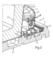
- Fig. 2 is in an enlarged partial view in section the arrangement 1 according to Fig. 1 shown, wherein the section in the area of the engine room 5 is shown here.
- the engine room 5 is bounded by a wall 13 to a front side 11 of the household refrigerating appliance 2, on which a door 12 is arranged.
- the wall 13 extends in the prior art straight from an upper edge 13a to a lower edge 13b.
- the bottom part 8 comprises a receiving region 14, in which the support rail 7 is arranged in the packaged state.
- the receiving region 14 is bounded in the depth direction (z-direction) by the bottom part or packaging bottom part 8, wherein a web 15 facing the first wall and adjoining it is formed and a second web 16 is formed opposite the latter and thus facing away from the wall 13.
- This first web 15 is designed to project vertically upwards and has a negligible slight rounding at its free upper end a constant thickness d of 17 mm.
- the support rail 7 is bounded on both sides by the webs 15 and 16.
- 17 relatively large amount of material is required by the shape of the first wall 13 and thereby limited foam part.
- a domestic refrigerator comprises a housing and a machine room, which is formed in a rear lower portion of the housing.
- This machine room is bounded on a front side of the housing side facing by a wall.
- the wall includes, at a lower end, an oblique first wall portion slanting from an upper wall cutting edge oriented towards the front side is designed to extend to a lower edge.
- a nose or an overhang is formed quasi in a lower region of the wall.
- the material requirement for the component which has this wall, in particular foam material saved.
- a coupling with parts of a packaging device can be improved by such a specific shaping, so that a position-fixed and stable packaging of the household refrigerating appliance is made possible.
- a carrier rail for a compressor which is arranged in the machine room, thereby an improved positioning on the one hand and yet on the other hand, improved accessibility on the other hand reachable.
- Another significant advantage results from the course of the wall and in particular of the first wall section to the effect that the ventilation of the engine room is improved during operation of the device. Because of the specific ground level position of the first wall portion and the orientation of the air flow around components, in particular a compressor, favors in the engine room around, so that the cooling is improved. It also gives us a kind of flow line or flow guidance. In particular, a boundary for a defined flow line of a cooling air flow in a region facing the front side in the engine room is therefore formed by the first oblique wall section for cooling a component in the engine room (viewed from the front side).
- a second wall section which is oriented steeper than the first wall section, is then formed on the upper wall section edge.
- the second edge delimits the wall downwards.
- the orientation and the position of this first wall section are thereby concretized.
- a measure of a horizontal connecting line between the lower edge and an intersection between the horizontal connecting line and a vertical connecting line formed between the upper wall cutting edge and the horizontal connecting line is> 35 mm, in particular> 50 mm.
- a receiving space designed for a packaging part is formed underneath the first inclined wall section.
- the invention relates to an arrangement with a household refrigerator according to the invention or an advantageous embodiment thereof, and a packaging device which surrounds the household refrigerator.
- the packaging device comprises at least one wedge-shaped packaging part, which extends into the receiving space or is arranged therein.
- Characterized the positional fixing of the device is favored in the packaging device, so that both a lying, and thus with the door of the device pointing to the ground, as well as a stationary transport is easily possible, in particular without further stabilizing additional parts is achieved in the package.
- the packaging device has two such wedge-shaped packaging parts which are spaced apart from each other, but are positioned in a linear connection to each other, wherein the two packaging parts are arranged along the width of the engine room and are each positioned in the receiving space. Due to the specific design as a wedge-shaped packaging parts a particularly noteworthy geometry is provided, which fills the receiving space as voluminous as possible, on the other hand a very large contact surface between the packaging part and the first wall section is created.
- the wedge-shaped structure favors the above-mentioned advantages with regard to a positionally reliable arrangement of the household refrigerating appliance.
- a horizontal bottom dimension of the wedge-shaped packaging part is between 50 mm and 60 mm, in particular between 53 mm and 57 mm.
- the wedge-shaped packaging part is integrated in a packaging bottom part.
- the number of components of the packaging device is reduced and a particularly stable and positionally secure arrangement of the wedge-shaped packaging part is achieved.
- particularly high load-bearing forces can be absorbed by such a configuration.
- the wedge-shaped packaging part with its side facing away from the first wall portion bounded in the packaging bottom part receiving space of a compressor of a refrigeration cycle of the household refrigerator.
- An arrangement 1 of an embodiment of the invention also comprises a household refrigerating appliance 2 and a packaging device 3.
- the further embodiment of the household refrigerating appliance 2 is analogous to the explanation in FIG Fig. 1 , so that here also in a housing 4 a arranged in the lower rear area engine room 5 with a compressor 6 and a support rail 7 are provided.
- the engine room 5 is bounded laterally by walls of the housing 4, but formed open to the rear.
- the packaging device 3 here too comprises a packaging bottom part 8 and head cushions 9 and 10.
- Fig. 3 a rear view of the household refrigerator 2 and the packaging bottom part 8 is shown.
- the machine room 5 is limited in the depth direction and thus in the z direction to the front side 11 through a wall 13 which defines the contour of a foam part on the machine room side.
- a first wall section 13c is formed in the lower region of the wall 13.
- the wall 13 extends over substantially the entire width (extension in the x-direction) of the machine room 5.
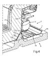
- the first wall section 13c is in the sectional view according to FIG Fig. 4 , which symbolizes a sectional view along the section line IV-IV and thus a horizontal section in the yz plane.
- the first wall portion 13c is oriented obliquely inclined, but formed in a straight line in the sectional view.
- the first wall section 13c is thus inclined downwardly from an upper wall section edge 131c and inclined towards the front side 11, and opens into the lower edge 13b of the wall 13.
- this first wall section 13c is formed so that a measure of the horizontal connecting line between the lower edge 13b and an intersection between the horizontal connecting line and a vertical connecting line formed between the upper wall section edge 131c and the horizontal connecting line 45 mm, in particular> 50 mm.
- the first wall section 13c is dimensioned in the vertical direction and thus in the y direction over a maximum of 1/3 of the vertical height of the entire wall 13.
- a receiving space 18 is formed underneath, which is designed to receive a wedge-shaped packaging part 19.
- This wedge-shaped packaging part 19 is formed integrally with the packaging base part 8, wherein this packaging base part 8 may be formed in particular from styrofoam.
- two such packaging parts 19 are provided in the width direction of the machine room, which are spaced from each other, but are positioned on a straight connecting line in series with each other.
- a packing part 19 has a horizontal bottom dimension b, which is preferably between 53 mm and 57 mm, especially between 55 mm and 56 mm, measured.
- the wedge-shaped packing part 19 bears against the first wall section 13c with an oblique flank 19a.
- Fig. 4 opens at the upper Wandabismerand 131c, a second wall portion 13d of the wall 13, which is oriented steeper compared to the first wall portion 13c.
- the wall 13 thus comprises over its entire course between the upper edge 13a and the lower edge 13b a non-rectilinear course and comprises in the context in the upper Wandabexcellentrand 131c a kink.
- the compressor 6 is also sufficiently cooled on its front side, which faces the front side 11 when the household refrigerating appliance 2 is viewed from the front side 11.
- the cooling air is passed through the wall section 13 c defined and can reach in a greater amount in this area of the engine room 5. An improved cooling concept for cooling the compressor 6 is thereby accompanied.
- the receiving area 14 on the outside and thus on the side facing away from the wall 13 has no web 16 which would completely cover the support rail 7 front side and thus higher than the support rail 7 would be.
- the mounting rail 7 is even free on this outside and is therefore fully accessible even in the packaged state.
Landscapes
- Engineering & Computer Science (AREA)
- Chemical & Material Sciences (AREA)
- Combustion & Propulsion (AREA)
- Physics & Mathematics (AREA)
- Mechanical Engineering (AREA)
- Thermal Sciences (AREA)
- General Engineering & Computer Science (AREA)
- Packaging Of Machine Parts And Wound Products (AREA)
- Refrigerator Housings (AREA)
- Devices That Are Associated With Refrigeration Equipment (AREA)
Abstract
Description
- Die Erfindung betrifft ein Haushaltskältegerät mit einem Gehäuse und einem Maschinenraum, der an einem hinteren unteren Bereich des Gehäuses ausgebildet ist, und der auf einer einer Frontseite des Gehäuses zugewandten Seite durch eine Wand begrenzt ist. Des Weiteren betrifft die Erfindung eine Anordnung mit einem derartigen Haushaltskältegerät und einer Verpackungsvorrichtung.
- Haushaltskältegeräte werden werksseitig zur Auslieferung verpackt. Dabei ist vorgesehen, dass am Boden und im Deckenbereich stabilere Verpackungsteile, insbesondere aus Styropor, vorgesehen sind, die als Kopfpolster und Bodenplatte bezeichnet werden. Darüber hinaus umfasst eine bekannte Verpackungsvorrichtung auch eine umgebende Hülle, die aus Pappe oder Karton ausgebildet ist.
- Haushaltskältegeräte umfassen in einem unteren hinteren Bereich eines Gehäuses einen Maschinenraum, in dem mehrere Komponenten angeordnet sind. So ist in dem Zusammenhang beispielsweise ein Verdichter eines Kältekreislaufs positioniert. Der Maschinenraum ist nach hinten offen ausgebildet und der Verdichter sitzt auf einer speziellen Tragschiene.
- In
Fig. 1 ist in einer perspektivischen Darstellung eine Anordnung 1 gezeigt, die ein Haushaltskältegerät 2 und eine Verpackungsvorrichtung 3, von welcher nur einige Teile dargestellt sind, umfasst. Ein Gehäuse 4 des Haushaltskältegeräts 2 ist, wie bereits erwähnt, in einem hinteren unteren Bereich mit einem Maschinenraum 5 ausgebildet. In diesem sitzt ein Verdichter 6 auf einer Tragschiene 7. Die Verpackungsvorrichtung 3 umfasst eine Bodenteil 8 und im Deckenbereich des Haushaltskältegeräts 2 angeordnete längliche Kopfpolster 9 und 10. - In
Fig. 2 ist in einer vergrößerten Teildarstellung im Schnitt die Anordnung 1 gemäßFig. 1 gezeigt, wobei hier der Ausschnitt im Bereich des Maschinenraums 5 gezeigt ist. - Der Maschinenraum 5 ist zu einer Frontseite 11 des Haushaltskältegeräts 2, an welcher auch eine Tür 12 angeordnet ist, durch eine Wand 13 begrenzt. Die Wand 13 verläuft bei dem Stand der Technik geradlinig von einem oberen Rand 13a zu einem unteren Rand 13b. Der Bodenteil 8 umfasst einen Aufnahmebereich 14, in den im verpackten Zustand die Tragschiene 7 angeordnet ist. Der Aufnahmebereich 14 ist in Tiefenrichtung (z-Richtung) durch das Bodenteil beziehungsweise Verpackungsbodenteil 8 begrenzt, wobei hier ein der ersten Wand zugewandter und daran anliegender Steg 15 ausgebildet ist und diesem gegenüberliegend und somit der Wand 13 abgewandt ein zweiter Steg 16 ausgebildet ist. Dieser erste Steg 15 ist vertikal nach oben ragend ausgebildet und weist bis auf vernachlässigbare geringe Abrundungen an seinem freien oberen Ende eine konstante Dicke d von 17 mm auf.
- Bei dieser Ausgestaltung ist es daher erforderlich, dass zum Halten des Haushaltskältegeräts in dem Verpackungsbodenteil 8 die Trägerschiene 7 beidseits durch die Stege 15 und 16 begrenzt ist. Darüber hinaus ist durch die Formgebung der ersten Wand 13 und einem dadurch begrenzten Schaumteil 17 relativ viel Material erforderlich.
- Bei weiteren bekannten Ausführungen ist neben den Kopfpolstern 9 und 10 zusätzlich dann noch eine Anordnung von Eckpolstern, die sich an den hinteren Rändern des Gehäuses zwischen den Kopfpolstern 9 und 10 und dem Verpackungsbodenteil 8 erstrecken, vorgesehen. Dadurch ist auch der Verpackungsmaterialaufwand sehr hoch.
- Es ist Aufgabe der vorliegenden Erfindung, ein Haushaltskältegerät zu schaffen, welches positionsstabil verpackt werden kann und ein geringerer Materialaufwand erforderlich ist.
- Diese Aufgabe wird durch ein Haushaltskältegerät und eine Anordnung gemäß den unabhängigen Ansprüchen gelöst.
- Ein erfindungsgemäßes Haushaltskältegerät umfasst ein Gehäuse und einen Maschinenraum, der in einem hinteren unteren Bereich des Gehäuses ausgebildet ist. Dieser Maschinenraum ist auf einer einer Frontseite des Gehäuses zugewandten Seite durch eine Wand begrenzt. Die Wand umfasst an einem unteren Ende einen schrägen ersten Wandabschnitt, der ausgehend von einem oberen Wandabschnittrand schräg nach vorne zur Frontseite hin orientiert bis zu einem unteren Rand verlaufend ausgebildet ist. Durch eine derartige Ausgestaltung wird quasi in einem unteren Bereich der Wand eine Nase beziehungsweise ein Überhang ausgebildet. Durch eine derartige Ausgestaltung wird der Materialbedarf für das Bauteil, welches diese Wand aufweist, insbesondere Schaummaterial, eingespart. Darüber hinaus lässt sich durch eine derartige spezifische Formgebung eine Kopplung mit Teilen einer Verpackungsvorrichtung verbessern, so dass eine positionsfixierte und stabile Verpackung des Haushaltskältegeräts ermöglicht ist. Gerade im Bereich des Maschinenraums und einer Trägerschiene für einen Verdichter, der im Maschinenraum angeordnet ist, ist dadurch eine verbesserte Positionierung einerseits und dennoch auf der anderen Seite auch eine verbesserte Zugänglichkeit andererseits erreichbar.
- Ein weiterer wesentlicher Vorteil ergibt sich durch den Verlauf der Wand und insbesondere des ersten Wandabschnitts dahingehend, dass die Durchlüftung des Maschinenraums im Betrieb des Geräts verbessert ist. Denn durch die spezifische bodennahe Lage des ersten Wandabschnitts und die Orientierung wird die Luftströmung um Bauteile, insbesondere einem Verdichter, im Maschinenraum herum begünstigt, so dass die Kühlung verbessert ist. Es wir dadurch auch eine Art Strömungsleitung bzw. Strömungsführung vorgegeben. Insbesondere ist daher durch den ersten schrägen Wandabschnitt eine Begrenzung für eine definierte Strömungsleitung einer Kühlluftströmung in einem der Frontseite zugewandten Bereich im Maschinenraum zur frontseitigen (bei Betrachtung des Geräts von der Frontseite her) Kühlung eines Bauteils im Maschinenraum ausgebildet.
- Vorzugsweise ist vorgesehen, dass an den oberen Wandabschnittrand anschließend ein zweiter Wandabschnitt ausgebildet ist, der steiler orientiert ist als der erste Wandabschnitt.
- Insbesondere ist vorgesehen, dass der zweite Rand die Wand nach unten hin begrenzt. Die Orientierung und die Lage dieses ersten Wandabschnitts sind dadurch konkretisiert. Die oben genannten Vorteile treten dadurch nochmals verbessert zutage.
- Vorzugsweise ist vorgesehen, dass ein Maß einer horizontalen Verbindungslinie zwischen dem unteren Rand und einem Schnittpunkt zwischen der horizontalen Verbindungslinie und einer zwischen dem oberen Wandabschnittrand und der horizontalen Verbindungslinie ausgebildeten vertikalen Verbindungslinie > 35 mm, insbesondere > 50 mm, beträgt. Durch eine derartige Ausgestaltung ist ein relativ großer Raum unter diesem ersten Wandabschnitt geschaffen, der dann vorzugsweise als Aufnahmeraum für ein Verpackungsteil ausgebildet ist. Durch die Größe und Form dieses Raums kann auch ein dahingehend spezifiziertes Verpackungsteil aufgenommen werden, welches dann die stabile Positionierung entsprechend begünstigt. Dennoch ist eine Materialeinsparung erreicht.
- Vorzugsweise ist vorgesehen, dass durch den ersten schrägen Wandabschnitt ein darunter ausgebildeter Aufnahmeraum für ein Verpackungsteil ausgebildet ist.
- Des Weiteren betrifft die Erfindung eine Anordnung mit einem erfindungsgemäßen Haushaltskältegerät oder einer vorteilhaften Ausgestaltung davon, und einer Verpackungsvorrichtung, welche das Haushaltskältegerät umgibt. Die Verpackungsvorrichtung umfasst zumindest ein keilförmiges Verpackungsteil, welches sich in den Aufnahmeraum hinein erstreckt beziehungsweise darin angeordnet ist.
- Dadurch wird die positionelle Fixierung des Geräts in der Verpackungsvorrichtung begünstigt, so dass dadurch sowohl ein liegender, und somit mit der Tür des Geräts zum Boden zeigend, als auch ein stehender Transport problemlos ermöglicht ist, insbesondere ohne weitere stabilisierende Zusatzteile in der Verpackung erreicht ist.
- Bei einer vorteilhaften Ausführung ist vorgesehen, dass die Verpackungsvorrichtung zwei derartige keilförmige Verpackungsteile aufweist, die beabstandet zueinander angeordnet sind, jedoch in einer geradlinigen Verbindung zueinander positioniert sind, wobei die beiden Verpackungsteile entlang der Breite des Maschinenraums angeordnet sind und jeweils in dem Aufnahmeraum positioniert sind. Durch die spezifische Ausgestaltung als keilförmige Verpackungsteile wird eine besonders hervorzuhebende Geometrie bereitgestellt, die den Aufnahmeraum möglichst voluminös ausfüllt, andererseits eine sehr große Anlagefläche zwischen dem Verpackungsteil und dem ersten Wandabschnitt geschaffen ist. Durch die keilförmige Struktur werden die oben genannten Vorteile bezüglich einer positionssicheren Anordnung des Haushaltskältegeräts begünstigt.
- Vorzugsweise ist vorgesehen, dass ein horizontales Bodenmaß des keilförmigen Verpackungsteils zwischen 50 mm und 60 mm, insbesondere zwischen 53 mm und 57 mm, beträgt. Diese spezifischen Wertangaben ermöglichen besonders viel an Einsparung des Schaummaterials, welches durch diese Wand in seiner Kontur geometrisch definiert ist, und gestalten das Verpackungsteil auch in der Keilform sehr belastbar.
- Vorzugsweise ist vorgesehen, dass das keilförmige Verpackungsteil in ein Verpackungsbodenteil integriert ist. Dadurch wird die Bauteilzahl der Verpackungsvorrichtung reduziert und eine besonders stabile und positionssichere Anordnung des keilförmigen Verpackungsteils erreicht. Nicht zuletzt können durch eine derartige Ausgestaltung auch besonders hohe Tragkräfte aufgenommen werden.
- Vorzugsweise ist vorgesehen, dass das keilförmige Verpackungsteil mit seiner dem ersten Wandabschnitt abgewandten Seite einen im Verpackungsbodenteil ausgebildeten Aufnahmeraum eines Verdichters eines Kältekreislaufs des Haushaltskältegeräts begrenzt.
- Weitere Merkmale der Erfindung ergeben sich aus den Ansprüchen, den Figuren und der Figurenbeschreibung. Die vorstehend in der Beschreibung genannten Merkmale und Merkmalskombinationen, sowie die nachfolgend in der Figurenbeschreibung genannten und/oder in den Figuren alleine gezeigten Merkmale und Merkmalskombinationen sind nicht nur in der jeweils angegebenen Kombination, sondern auch in anderen Kombinationen oder in Alleinstellung verwendbar, ohne den Rahmen der Erfindung zu verlassen. Es sind somit auch Ausführungen von der Erfindung als umfasst und offenbart anzusehen, die in den Figuren nicht explizit gezeigt und erläutert sind, jedoch durch separierte Merkmalskombinationen aus den erläuterten Ausführungen hervorgehen und erzeugbar sind.
- Ein Ausführungsbeispiel der Erfindung wird nachfolgend anhand schematischer Zeichnungen näher erläutert. Es zeigen:
- Fig. 1
- eine perspektivische Darstellung einer Anordnung mit einem Haushaltskältegerät und Teilen einer Verpackungsvorrichtung gemäß dem Stand der Technik;
- Fig. 2
- eine perspektivische Schnittdarstellung eines Teilbereichs der Anordnung gemäß
Fig. 1 , wie sie aus dem Stand der Technik bekannt ist; - Fig. 3
- eine Rückansicht eines Teilausschnitts eines erfindungsgemäßen Haushaltskältegeräts mit einer Verpackungsvorrichtung im Bereich des Maschinenraums, und
- Fig. 4
- eine perspektivische Schnittdarstellung eines Teilbereichs einer erfindungsgemäßen Ausführung einer Anordnung an einer Schnittposition im Bereich der Darstellung gem.
Fig. 2 . - In den Figuren werden gleiche oder funktionsgleiche Elemente mit den gleichen Bezugszeichen versehen.
- Eine Anordnung 1 eines Ausführungsbeispiels der Erfindung umfasst ebenfalls ein Haushaltskältegerät 2 und eine Verpackungsvorrichtung 3. Die weitere Ausgestaltung des Haushaltskältegeräts 2 ist analog zur Erläuterung in
Fig. 1 , so dass auch hier in einem Gehäuse 4 ein im unteren hinteren Bereich angeordneter Maschinenraum 5 mit einem Verdichter 6 und einer Tragschiene 7 vorgesehen sind. Der Maschinenraum 5 ist seitlich durch Wände des Gehäuses 4 begrenzt, jedoch nach hinten offen ausgebildet. Die Verpackungsvorrichtung 3 umfasst auch hier ein Verpackungsbodenteil 8 und Kopfpolster 9 und 10. - In
Fig. 3 ist eine Rückansicht des Haushaltskältegeräts 2 und des Verpackungsbodenteils 8 gezeigt. Wie zu erkennen ist, ist der Maschinenraum 5 in Tiefenrichtung und somit in z-Richtung betrachtet zur Frontseite 11 hin durch eine Wand 13 begrenzt, die die Kontur eines Schaumteils maschinenraumseitig definiert. - In einem wesentlichen Unterschied zur Ausgestaltung der Wand 13, wie sie im Stand der Technik gemäß
Fig. 2 gezeigt ist, ist hier vorgesehen, dass ein erster Wandabschnitt 13c im unteren Bereich der Wand 13 gebildet ist. Die Wand 13 erstreckt sich über im Wesentlichen die gesamte Breite (Erstreckung in x-Richtung) des Maschinenraums 5. Der erste Wandabschnitt 13c ist in der Schnittdarstellung gemäßFig. 4 , die eine Schnittansicht entlang der Schnittlinie IV-IV und somit einen Horizontalschnitt in der y-z-Ebene symbolisiert, dargestellt. - Der erste Wandabschnitt 13c ist schräg geneigt orientiert, dabei jedoch in sich geradlinig in der Schnittdarstellung gebildet. Der erste Wandabschnitt 13c ist somit von einem oberen Wandabschnittrand 131c aus betrachtet nach unten und zur Frontseite 11 hin geneigt und mündet in den unteren Rand 13b der Wand 13.
- Es ist vorgesehen, dass die Ausgestaltung und Neigung dieses ersten Wandabschnitts 13c so gebildet ist, dass ein Maß der horizontalen Verbindungslinie zwischen dem unteren Rand 13b und einem Schnittpunkt zwischen der horizontalen Verbindungslinie und einer zwischen dem oberen Wandabschnittsrand 131c und der horizontalen Verbindungslinie ausgebildeten vertikalen Verbindungslinie > 45 mm, insbesondere > 50 mm, beträgt.
- Der erste Wandabschnitt 13c bemisst sich in vertikaler Richtung und somit in y-Richtung über maximal 1/3 der vertikalen Höhe der gesamten Wand 13.
- Durch die Ausgestaltung und Orientierung des ersten Wandabschnitts 13c wird darunter ein Aufnahmeraum 18 gebildet, der zur Aufnahme eines keilförmigen Verpackungsteils 19 ausgebildet ist. Dieses keilförmige Verpackungsteil 19 ist einstückig mit dem Verpackungsbodenteil 8 ausgebildet, wobei dieses Verpackungsbodenteil 8 insbesondere aus Styropor gebildet sein kann.
- Wie in dem Zusammenhang aus der Darstellung in
Fig. 3 zu erkennen ist, sind in Breitenrichtung des Maschinenraums 5 zwei derartige Verpackungsteile 19 vorgesehen, die beabstandet zueinander angeordnet sind, jedoch auf einer geraden Verbindungslinie in Reihe zueinander positioniert sind. - Wie aus der Darstellung in
Fig. 4 zu erkennen ist, weist ein Verpackungsteil 19 ein horizontales Bodenmaß b auf, welches sich vorzugsweise zwischen 53 mm und 57 mm, insbesondere zwischen 55 mm und 56 mm, bemisst. Das keilförmige Verpackungsteil 19 liegt mit einer schrägen Flanke 19a an dem ersten Wandabschnitt 13c an. - Wie aus der Darstellung in
Fig. 4 explizit zu entnehmen ist, mündet an den oberen Wandabschnittrand 131c ein zweiter Wandabschnitt 13d der Wand 13, wobei dieser im Vergleich zum ersten Wandabschnitt 13c steiler orientiert ist. Die Wand 13 umfasst somit über ihren gesamten Verlauf zwischen dem oberen Rand 13a und dem unteren Rand 13b einen nicht geradlinigen Verlauf und umfasst in dem Zusammenhang in dem oberen Wandabschnittrand 131c eine Knickstelle. - Durch die bodennahe Anordnung und die schräge Orientierung des ersten Wandabschnitts 13c ist des Weiteren auch eine Begrenzung einer Strömungsleitung für eine Kühlluftströmung ausgebildet. Dadurch wird der Verdichter 6 auch an seiner Frontseite, die bei Betrachtung des Haushaltskältegeräts 2 von der Frontseite 11 her der Frontseite 11 zugewandt ist, ausreichend gekühlt. Die Kühlluft wird durch den Wandabschnitt 13c definiert geleitet und kann in größerer Menge auch in diesen Bereich des Maschinenraums 5 gelangen. Ein verbessertes Kühlkonzept zum Kühlen des Verdichters 6 ist dadurch einhergehend.
- Darüber hinaus ist in der Ausgestaltung gemäß
Fig. 3 undFig. 4 vorgesehen, dass der Aufnahmebereich 14 außenseitig und somit auf der der Wand 13 abgewandten Seite keinen Steg 16 aufweist, der die Tragschiene 7 frontseitig vollständig abdecken würde und somit höher als die Tragschiene 7 wäre. Insbesondere liegt die Tragschiene 7 sogar an dieser Außenseite frei und ist dementsprechend auch im verpackten Zustand uneingeschränkt zugänglich. -
- 1
- Anordnung
- 2
- Haushaltskältegerät
- 3
- Verpackungsvorrichtung
- 4
- Gehäuse
- 5
- Maschinenraum
- 6
- Verdichter
- 7
- Tragschiene
- 8
- Bodenteil
- 9
- Kopfpolster
- 10
- Kopfpolster
- 11
- Frontseite
- 12
- Tür
- 13
- Wand
- 13a
- Oberer Rand
- 13b
- Unterer Rand
- 13c
- Erster Wandabschnitt
- 131c
- Oberer Wandabschnittrand
- 13d
- Zweiter Wandabschnitt
- 14
- Aufnahmeraum
- 15
- Erster Steg
- 16
- Zweiter Steg
- 17
- Schaumteil
- 18
- Aufnahmeraum
- 19
- Verpackungsteil
- 19a
- Flanke
- b
- Bodenmaß
- d
- Dicke
Claims (11)
- Haushaltskältegerät (2) mit einem Gehäuse (4) und einem Maschinenraum (5), der in einem hinteren unteren Bereich des Gehäuses (4) ausgebildet ist, und der auf einer einer Frontseite (11) des Gehäuses (4) zugewandten Seite durch eine Wand (13) begrenzt ist, dadurch gekennzeichnet, dass die Wand (13) an einem unteren Ende einen schrägen ersten Wandabschnitt (13c) aufweist, der ausgehend von einem oberen Wandabschnittrand (131c) schräg nach vorne zur Frontseite (11) hin orientiert bis zu einem unteren Rand (13b) verlaufend ausgebildet ist.
- Haushaltskältegerät (2) nach Anspruch 1, dadurch gekennzeichnet, dass an den oberen Wandabschnittrand (131c) anschließend ein zweiter Wandabschnitt (13d) ausgebildet ist, der steiler orientiert ist als der erste Wandabschnitt (13c).
- Haushaltskältegerät (2) nach Anspruch 1 oder 2, dadurch gekennzeichnet, dass der zweite Rand (13b) die Wand (13) nach unten hin begrenzt.
- Haushaltskältegerät (2) nach einem der vorhergehenden Ansprüche, dadurch gekennzeichnet, dass ein Maß einer horizontalen Verbindungslinie zwischen dem unteren Rand (13b) und einem Schnittpunkt zwischen der horizontalen Verbindungslinie und einer zwischen dem oberen Wandabschnittrand (131 c) und der horizontalen Verbindungslinie ausgebildeten vertikale Verbindungslinie größer 35 mm, insbesondere größer 50 mm, beträgt.
- Haushaltskältegerät (2) nach einem der vorhergehenden Ansprüche, dadurch gekennzeichnet, dass sich der erste Wandabschnitt (13c) über maximal ein Drittel der vertikalen Höhe der Wand (13) erstreckt.
- Haushaltskältegerät (2) nach einem der vorhergehenden Ansprüche, dadurch gekennzeichnet, dass durch den ersten schrägen Wandabschnitt (13c) ein darunter ausgebildeter Aufnahmeraum (18) für ein Verpackungsteil (19) ausgebildet ist.
- Haushaltskältegerät (2) nach einem der vorhergehenden Ansprüche, dadurch gekennzeichnet, dass durch den ersten schrägen Wandabschnitt (13c) eine Begrenzung für eine definierte Strömungsleitung einer Kühlluftströmung in einem der Frontseite (11) zugewandten Bereich im Maschinenraum (5) zur frontseitigen Kühlung eines Bauteils (6) im Maschinenraum (5) ausgebildet ist.
- Anordnung (1) mit einem Haushaltskältegerät (2) nach einem der vorhergehenden Ansprüche, und einer Verpackungsvorrichtung (3), welche das Haushaltskältegerät (2) umgibt, welche zumindest ein keilförmiges Verpackungsteil (19), insbesondere zwei keilförmige Verpackungsteile (19), aufweist, welches in dem Aufnahmeraum (18) angeordnet ist.
- Anordnung (1) nach Anspruch 8, dadurch gekennzeichnet, dass ein horizontales Bodenmaß (b) des keilförmigen Verpackungsteils (19) zwischen 50 mm und 60 mm, insbesondere zwischen 53 mm und 57 mm, beträgt.
- Anordnung (1) nach Anspruch 8 oder 9, dadurch gekennzeichnet, dass das keilförmige Verpackungsteil (19) in ein Verpackungsbodenteil (8) integriert ist.
- Anordnung (1) nach Anspruch 10, dadurch gekennzeichnet, dass das keilförmige Verpackungsteil (19) mit seiner dem ersten Wandabschnitt (13c) abgewandten Seite einen im Verpackungsbodenteil (8) ausgebildeten Aufnahmeraum (14) für eine Tragschiene (7) eines Verdichters (6) eines Kältekreislaufs des Haushaltskältegeräts (2) begrenzt.
Priority Applications (1)
| Application Number | Priority Date | Filing Date | Title |
|---|---|---|---|
| PL14170851T PL2811246T3 (pl) | 2013-06-03 | 2014-06-03 | Układ z urządzeniem chłodniczym gospodarstwa domowego i urządzenie pakujące |
Applications Claiming Priority (1)
| Application Number | Priority Date | Filing Date | Title |
|---|---|---|---|
| DE102013210253.4A DE102013210253A1 (de) | 2013-06-03 | 2013-06-03 | Haushaltskältegerät mit schrägem Wandabschnitt zur Begrenzung eines Maschinenraums sowie Anordnung mit einem derartigen Haushaltskältegerät und einer Verpackungsvorrichtung |
Publications (3)
| Publication Number | Publication Date |
|---|---|
| EP2811246A2 true EP2811246A2 (de) | 2014-12-10 |
| EP2811246A3 EP2811246A3 (de) | 2015-09-09 |
| EP2811246B1 EP2811246B1 (de) | 2018-03-07 |
Family
ID=50884709
Family Applications (1)
| Application Number | Title | Priority Date | Filing Date |
|---|---|---|---|
| EP14170851.1A Active EP2811246B1 (de) | 2013-06-03 | 2014-06-03 | Anordnung mit einem Haushaltskältegerät und einer Verpackungsvorrichtung |
Country Status (4)
| Country | Link |
|---|---|
| EP (1) | EP2811246B1 (de) |
| CN (1) | CN104215021B (de) |
| DE (1) | DE102013210253A1 (de) |
| PL (1) | PL2811246T3 (de) |
Families Citing this family (1)
| Publication number | Priority date | Publication date | Assignee | Title |
|---|---|---|---|---|
| DE102017214245A1 (de) * | 2017-08-16 | 2019-02-21 | BSH Hausgeräte GmbH | Haushaltskältegerätevorrichtung |
Family Cites Families (8)
| Publication number | Priority date | Publication date | Assignee | Title |
|---|---|---|---|---|
| JPS5742873Y2 (de) * | 1977-12-27 | 1982-09-21 | ||
| JPS5951785A (ja) * | 1982-09-16 | 1984-03-26 | Masahisa Takeda | ハトムギ酒の製造方法 |
| JPS5951785U (ja) * | 1982-09-28 | 1984-04-05 | 日本電気ホームエレクトロニクス株式会社 | 梱包装置 |
| JP2657086B2 (ja) * | 1989-01-11 | 1997-09-24 | 三洋電機株式会社 | 冷蔵庫の運搬用把手装置 |
| JP3789294B2 (ja) * | 2000-09-20 | 2006-06-21 | シャープ株式会社 | 冷蔵庫 |
| JP5081880B2 (ja) * | 2009-09-09 | 2012-11-28 | 日立アプライアンス株式会社 | 冷蔵庫 |
| JP5530850B2 (ja) * | 2010-07-30 | 2014-06-25 | 日立アプライアンス株式会社 | 冷蔵庫 |
| DE102010043270A1 (de) * | 2010-11-03 | 2012-05-03 | BSH Bosch und Siemens Hausgeräte GmbH | Haushaltsgerät |
-
2013
- 2013-06-03 DE DE102013210253.4A patent/DE102013210253A1/de not_active Withdrawn
-
2014
- 2014-05-29 CN CN201410232778.5A patent/CN104215021B/zh active Active
- 2014-06-03 EP EP14170851.1A patent/EP2811246B1/de active Active
- 2014-06-03 PL PL14170851T patent/PL2811246T3/pl unknown
Non-Patent Citations (1)
| Title |
|---|
| None |
Also Published As
| Publication number | Publication date |
|---|---|
| CN104215021B (zh) | 2018-10-16 |
| PL2811246T3 (pl) | 2018-07-31 |
| EP2811246B1 (de) | 2018-03-07 |
| DE102013210253A1 (de) | 2014-12-04 |
| CN104215021A (zh) | 2014-12-17 |
| EP2811246A3 (de) | 2015-09-09 |
Similar Documents
| Publication | Publication Date | Title |
|---|---|---|
| EP1850708B1 (de) | Vorrichtung zum aufhängen von artikeln oder zur halterung einer ablage und aufbau damit | |
| DE2810059C2 (de) | Anordnung von Motorkompressoreinheiten für Kühlsysteme | |
| DE3003924A1 (de) | Wagenkastenaufbau fuer strassen- und schienenfahrzeuge | |
| DE102009027881A1 (de) | Ventilatorbaugruppe für ein Kältegerät | |
| EP2562120B1 (de) | Vorrichtung zur Halterung von Führungsschienen für Personen- und Lastenaufzüge | |
| EP1187512B1 (de) | Strahlungsheizkörper zur Anordnung unter einem Kochfeld, insbesondere einer Glaskeramikplatte | |
| WO2018130547A1 (de) | Elektronikmodul und montagebasis mit einem elektronikmodul | |
| DE19731093B4 (de) | Bauelement zur Wärmedämmung | |
| EP3009045A1 (de) | Zarge für eine schublade mit einem zargenkörper sowie schublade und möbel mit einer schublade | |
| EP2811246B1 (de) | Anordnung mit einem Haushaltskältegerät und einer Verpackungsvorrichtung | |
| DE4014734C2 (de) | ||
| EP2062502A1 (de) | Lagerregal | |
| DE102015205231A1 (de) | Seitenblende eines Fahrzeugsitzes mit einer Deformationszone | |
| DE69413850T2 (de) | Verbesserungen an einem papierkorb und herstellungsverfahren | |
| DE3832256C2 (de) | ||
| EP2844108A1 (de) | Haltevorrichtung für ein tragelement eines schrankes sowie kühl-, gefrierschrank oder weinlagerungsschrank | |
| CH674392A5 (de) | ||
| DE2812062C2 (de) | ||
| EP2487372B1 (de) | Befestigungsanordnung und Verfahren zur Herstellung einer solchen | |
| DE112009005339B4 (de) | Fahrzeugkarosseriestruktur | |
| DE4440038C2 (de) | Explosionssperre für den Untertagebergbau | |
| DE102020207641A1 (de) | Innenbehälter mit spezifischer Form einer Auflagerippe, sowie Haushaltskältegerät | |
| DE602004009252T2 (de) | Aufzugseinrichtung beinhaltend eine Kabine mit Rahmen | |
| DE10213313A1 (de) | Kardantunnelhaltenetzanordnung | |
| DE102006041855A1 (de) | Stapelbare Transportverpackung |
Legal Events
| Date | Code | Title | Description |
|---|---|---|---|
| PUAI | Public reference made under article 153(3) epc to a published international application that has entered the european phase |
Free format text: ORIGINAL CODE: 0009012 |
|
| 17P | Request for examination filed |
Effective date: 20140603 |
|
| AK | Designated contracting states |
Kind code of ref document: A2 Designated state(s): AL AT BE BG CH CY CZ DE DK EE ES FI FR GB GR HR HU IE IS IT LI LT LU LV MC MK MT NL NO PL PT RO RS SE SI SK SM TR |
|
| AX | Request for extension of the european patent |
Extension state: BA ME |
|
| RAP1 | Party data changed (applicant data changed or rights of an application transferred) |
Owner name: BSH HAUSGERAETE GMBH |
|
| RIC1 | Information provided on ipc code assigned before grant |
Ipc: F25D 23/00 20060101AFI20150216BHEP |
|
| PUAL | Search report despatched |
Free format text: ORIGINAL CODE: 0009013 |
|
| AK | Designated contracting states |
Kind code of ref document: A3 Designated state(s): AL AT BE BG CH CY CZ DE DK EE ES FI FR GB GR HR HU IE IS IT LI LT LU LV MC MK MT NL NO PL PT RO RS SE SI SK SM TR |
|
| AX | Request for extension of the european patent |
Extension state: BA ME |
|
| RIC1 | Information provided on ipc code assigned before grant |
Ipc: F25D 23/00 20060101AFI20150731BHEP |
|
| R17P | Request for examination filed (corrected) |
Effective date: 20160309 |
|
| RBV | Designated contracting states (corrected) |
Designated state(s): AL AT BE BG CH CY CZ DE DK EE ES FI FR GB GR HR HU IE IS IT LI LT LU LV MC MK MT NL NO PL PT RO RS SE SI SK SM TR |
|
| GRAP | Despatch of communication of intention to grant a patent |
Free format text: ORIGINAL CODE: EPIDOSNIGR1 |
|
| INTG | Intention to grant announced |
Effective date: 20171006 |
|
| GRAS | Grant fee paid |
Free format text: ORIGINAL CODE: EPIDOSNIGR3 |
|
| GRAA | (expected) grant |
Free format text: ORIGINAL CODE: 0009210 |
|
| AK | Designated contracting states |
Kind code of ref document: B1 Designated state(s): AL AT BE BG CH CY CZ DE DK EE ES FI FR GB GR HR HU IE IS IT LI LT LU LV MC MK MT NL NO PL PT RO RS SE SI SK SM TR |
|
| REG | Reference to a national code |
Ref country code: GB Ref legal event code: FG4D Free format text: NOT ENGLISH |
|
| REG | Reference to a national code |
Ref country code: CH Ref legal event code: EP Ref country code: AT Ref legal event code: REF Ref document number: 977009 Country of ref document: AT Kind code of ref document: T Effective date: 20180315 |
|
| REG | Reference to a national code |
Ref country code: DE Ref legal event code: R096 Ref document number: 502014007503 Country of ref document: DE |
|
| REG | Reference to a national code |
Ref country code: IE Ref legal event code: FG4D Free format text: LANGUAGE OF EP DOCUMENT: GERMAN |
|
| REG | Reference to a national code |
Ref country code: NL Ref legal event code: MP Effective date: 20180307 |
|
| REG | Reference to a national code |
Ref country code: LT Ref legal event code: MG4D |
|
| PG25 | Lapsed in a contracting state [announced via postgrant information from national office to epo] |
Ref country code: ES Free format text: LAPSE BECAUSE OF FAILURE TO SUBMIT A TRANSLATION OF THE DESCRIPTION OR TO PAY THE FEE WITHIN THE PRESCRIBED TIME-LIMIT Effective date: 20180307 Ref country code: LT Free format text: LAPSE BECAUSE OF FAILURE TO SUBMIT A TRANSLATION OF THE DESCRIPTION OR TO PAY THE FEE WITHIN THE PRESCRIBED TIME-LIMIT Effective date: 20180307 Ref country code: HR Free format text: LAPSE BECAUSE OF FAILURE TO SUBMIT A TRANSLATION OF THE DESCRIPTION OR TO PAY THE FEE WITHIN THE PRESCRIBED TIME-LIMIT Effective date: 20180307 Ref country code: NO Free format text: LAPSE BECAUSE OF FAILURE TO SUBMIT A TRANSLATION OF THE DESCRIPTION OR TO PAY THE FEE WITHIN THE PRESCRIBED TIME-LIMIT Effective date: 20180607 Ref country code: FI Free format text: LAPSE BECAUSE OF FAILURE TO SUBMIT A TRANSLATION OF THE DESCRIPTION OR TO PAY THE FEE WITHIN THE PRESCRIBED TIME-LIMIT Effective date: 20180307 Ref country code: CY Free format text: LAPSE BECAUSE OF FAILURE TO SUBMIT A TRANSLATION OF THE DESCRIPTION OR TO PAY THE FEE WITHIN THE PRESCRIBED TIME-LIMIT Effective date: 20180307 |
|
| PG25 | Lapsed in a contracting state [announced via postgrant information from national office to epo] |
Ref country code: SE Free format text: LAPSE BECAUSE OF FAILURE TO SUBMIT A TRANSLATION OF THE DESCRIPTION OR TO PAY THE FEE WITHIN THE PRESCRIBED TIME-LIMIT Effective date: 20180307 Ref country code: LV Free format text: LAPSE BECAUSE OF FAILURE TO SUBMIT A TRANSLATION OF THE DESCRIPTION OR TO PAY THE FEE WITHIN THE PRESCRIBED TIME-LIMIT Effective date: 20180307 Ref country code: GR Free format text: LAPSE BECAUSE OF FAILURE TO SUBMIT A TRANSLATION OF THE DESCRIPTION OR TO PAY THE FEE WITHIN THE PRESCRIBED TIME-LIMIT Effective date: 20180608 Ref country code: BG Free format text: LAPSE BECAUSE OF FAILURE TO SUBMIT A TRANSLATION OF THE DESCRIPTION OR TO PAY THE FEE WITHIN THE PRESCRIBED TIME-LIMIT Effective date: 20180607 Ref country code: RS Free format text: LAPSE BECAUSE OF FAILURE TO SUBMIT A TRANSLATION OF THE DESCRIPTION OR TO PAY THE FEE WITHIN THE PRESCRIBED TIME-LIMIT Effective date: 20180307 |
|
| PG25 | Lapsed in a contracting state [announced via postgrant information from national office to epo] |
Ref country code: MT Free format text: LAPSE BECAUSE OF FAILURE TO SUBMIT A TRANSLATION OF THE DESCRIPTION OR TO PAY THE FEE WITHIN THE PRESCRIBED TIME-LIMIT Effective date: 20180307 |
|
| PG25 | Lapsed in a contracting state [announced via postgrant information from national office to epo] |
Ref country code: AL Free format text: LAPSE BECAUSE OF FAILURE TO SUBMIT A TRANSLATION OF THE DESCRIPTION OR TO PAY THE FEE WITHIN THE PRESCRIBED TIME-LIMIT Effective date: 20180307 Ref country code: EE Free format text: LAPSE BECAUSE OF FAILURE TO SUBMIT A TRANSLATION OF THE DESCRIPTION OR TO PAY THE FEE WITHIN THE PRESCRIBED TIME-LIMIT Effective date: 20180307 Ref country code: RO Free format text: LAPSE BECAUSE OF FAILURE TO SUBMIT A TRANSLATION OF THE DESCRIPTION OR TO PAY THE FEE WITHIN THE PRESCRIBED TIME-LIMIT Effective date: 20180307 Ref country code: NL Free format text: LAPSE BECAUSE OF FAILURE TO SUBMIT A TRANSLATION OF THE DESCRIPTION OR TO PAY THE FEE WITHIN THE PRESCRIBED TIME-LIMIT Effective date: 20180307 |
|
| PG25 | Lapsed in a contracting state [announced via postgrant information from national office to epo] |
Ref country code: SM Free format text: LAPSE BECAUSE OF FAILURE TO SUBMIT A TRANSLATION OF THE DESCRIPTION OR TO PAY THE FEE WITHIN THE PRESCRIBED TIME-LIMIT Effective date: 20180307 Ref country code: CZ Free format text: LAPSE BECAUSE OF FAILURE TO SUBMIT A TRANSLATION OF THE DESCRIPTION OR TO PAY THE FEE WITHIN THE PRESCRIBED TIME-LIMIT Effective date: 20180307 Ref country code: SK Free format text: LAPSE BECAUSE OF FAILURE TO SUBMIT A TRANSLATION OF THE DESCRIPTION OR TO PAY THE FEE WITHIN THE PRESCRIBED TIME-LIMIT Effective date: 20180307 |
|
| REG | Reference to a national code |
Ref country code: DE Ref legal event code: R097 Ref document number: 502014007503 Country of ref document: DE |
|
| PG25 | Lapsed in a contracting state [announced via postgrant information from national office to epo] |
Ref country code: PT Free format text: LAPSE BECAUSE OF FAILURE TO SUBMIT A TRANSLATION OF THE DESCRIPTION OR TO PAY THE FEE WITHIN THE PRESCRIBED TIME-LIMIT Effective date: 20180709 |
|
| PLBE | No opposition filed within time limit |
Free format text: ORIGINAL CODE: 0009261 |
|
| STAA | Information on the status of an ep patent application or granted ep patent |
Free format text: STATUS: NO OPPOSITION FILED WITHIN TIME LIMIT |
|
| PG25 | Lapsed in a contracting state [announced via postgrant information from national office to epo] |
Ref country code: DK Free format text: LAPSE BECAUSE OF FAILURE TO SUBMIT A TRANSLATION OF THE DESCRIPTION OR TO PAY THE FEE WITHIN THE PRESCRIBED TIME-LIMIT Effective date: 20180307 |
|
| REG | Reference to a national code |
Ref country code: CH Ref legal event code: PL |
|
| 26N | No opposition filed |
Effective date: 20181210 |
|
| GBPC | Gb: european patent ceased through non-payment of renewal fee |
Effective date: 20180607 |
|
| PG25 | Lapsed in a contracting state [announced via postgrant information from national office to epo] |
Ref country code: SI Free format text: LAPSE BECAUSE OF FAILURE TO SUBMIT A TRANSLATION OF THE DESCRIPTION OR TO PAY THE FEE WITHIN THE PRESCRIBED TIME-LIMIT Effective date: 20180307 |
|
| REG | Reference to a national code |
Ref country code: BE Ref legal event code: MM Effective date: 20180630 |
|
| REG | Reference to a national code |
Ref country code: IE Ref legal event code: MM4A |
|
| PG25 | Lapsed in a contracting state [announced via postgrant information from national office to epo] |
Ref country code: LU Free format text: LAPSE BECAUSE OF NON-PAYMENT OF DUE FEES Effective date: 20180603 Ref country code: MC Free format text: LAPSE BECAUSE OF FAILURE TO SUBMIT A TRANSLATION OF THE DESCRIPTION OR TO PAY THE FEE WITHIN THE PRESCRIBED TIME-LIMIT Effective date: 20180307 |
|
| PG25 | Lapsed in a contracting state [announced via postgrant information from national office to epo] |
Ref country code: LI Free format text: LAPSE BECAUSE OF NON-PAYMENT OF DUE FEES Effective date: 20180630 Ref country code: CH Free format text: LAPSE BECAUSE OF NON-PAYMENT OF DUE FEES Effective date: 20180630 Ref country code: GB Free format text: LAPSE BECAUSE OF NON-PAYMENT OF DUE FEES Effective date: 20180607 Ref country code: FR Free format text: LAPSE BECAUSE OF NON-PAYMENT OF DUE FEES Effective date: 20180630 Ref country code: IE Free format text: LAPSE BECAUSE OF NON-PAYMENT OF DUE FEES Effective date: 20180603 |
|
| PG25 | Lapsed in a contracting state [announced via postgrant information from national office to epo] |
Ref country code: BE Free format text: LAPSE BECAUSE OF NON-PAYMENT OF DUE FEES Effective date: 20180630 |
|
| PG25 | Lapsed in a contracting state [announced via postgrant information from national office to epo] |
Ref country code: HU Free format text: LAPSE BECAUSE OF FAILURE TO SUBMIT A TRANSLATION OF THE DESCRIPTION OR TO PAY THE FEE WITHIN THE PRESCRIBED TIME-LIMIT; INVALID AB INITIO Effective date: 20140603 |
|
| PG25 | Lapsed in a contracting state [announced via postgrant information from national office to epo] |
Ref country code: MK Free format text: LAPSE BECAUSE OF NON-PAYMENT OF DUE FEES Effective date: 20180307 |
|
| PG25 | Lapsed in a contracting state [announced via postgrant information from national office to epo] |
Ref country code: IS Free format text: LAPSE BECAUSE OF FAILURE TO SUBMIT A TRANSLATION OF THE DESCRIPTION OR TO PAY THE FEE WITHIN THE PRESCRIBED TIME-LIMIT Effective date: 20180707 |
|
| REG | Reference to a national code |
Ref country code: AT Ref legal event code: MM01 Ref document number: 977009 Country of ref document: AT Kind code of ref document: T Effective date: 20190603 |
|
| PG25 | Lapsed in a contracting state [announced via postgrant information from national office to epo] |
Ref country code: AT Free format text: LAPSE BECAUSE OF NON-PAYMENT OF DUE FEES Effective date: 20190603 |
|
| PGFP | Annual fee paid to national office [announced via postgrant information from national office to epo] |
Ref country code: IT Payment date: 20220630 Year of fee payment: 9 |
|
| PG25 | Lapsed in a contracting state [announced via postgrant information from national office to epo] |
Ref country code: IT Free format text: LAPSE BECAUSE OF NON-PAYMENT OF DUE FEES Effective date: 20230603 |
|
| PGFP | Annual fee paid to national office [announced via postgrant information from national office to epo] |
Ref country code: PL Payment date: 20250522 Year of fee payment: 12 Ref country code: DE Payment date: 20250630 Year of fee payment: 12 |
|
| PGFP | Annual fee paid to national office [announced via postgrant information from national office to epo] |
Ref country code: TR Payment date: 20250528 Year of fee payment: 12 |