EP2811479A1 - Interface utilisateur pour un système de simulation d'opération chirurgicale - Google Patents
Interface utilisateur pour un système de simulation d'opération chirurgicale Download PDFInfo
- Publication number
- EP2811479A1 EP2811479A1 EP13171086.5A EP13171086A EP2811479A1 EP 2811479 A1 EP2811479 A1 EP 2811479A1 EP 13171086 A EP13171086 A EP 13171086A EP 2811479 A1 EP2811479 A1 EP 2811479A1
- Authority
- EP
- European Patent Office
- Prior art keywords
- axis
- sensor
- rotation
- rigid shaft
- suspension portion
- Prior art date
- Legal status (The legal status is an assumption and is not a legal conclusion. Google has not performed a legal analysis and makes no representation as to the accuracy of the status listed.)
- Granted
Links
Images


Classifications
-
- G—PHYSICS
- G09—EDUCATION; CRYPTOGRAPHY; DISPLAY; ADVERTISING; SEALS
- G09B—EDUCATIONAL OR DEMONSTRATION APPLIANCES; APPLIANCES FOR TEACHING, OR COMMUNICATING WITH, THE BLIND, DEAF OR MUTE; MODELS; PLANETARIA; GLOBES; MAPS; DIAGRAMS
- G09B23/00—Models for scientific, medical, or mathematical purposes, e.g. full-sized devices for demonstration purposes
- G09B23/28—Models for scientific, medical, or mathematical purposes, e.g. full-sized devices for demonstration purposes for medicine
- G09B23/286—Models for scientific, medical, or mathematical purposes, e.g. full-sized devices for demonstration purposes for medicine for scanning or photography techniques, e.g. X-rays, ultrasonics
-
- G—PHYSICS
- G09—EDUCATION; CRYPTOGRAPHY; DISPLAY; ADVERTISING; SEALS
- G09B—EDUCATIONAL OR DEMONSTRATION APPLIANCES; APPLIANCES FOR TEACHING, OR COMMUNICATING WITH, THE BLIND, DEAF OR MUTE; MODELS; PLANETARIA; GLOBES; MAPS; DIAGRAMS
- G09B23/00—Models for scientific, medical, or mathematical purposes, e.g. full-sized devices for demonstration purposes
- G09B23/28—Models for scientific, medical, or mathematical purposes, e.g. full-sized devices for demonstration purposes for medicine
- G09B23/285—Models for scientific, medical, or mathematical purposes, e.g. full-sized devices for demonstration purposes for medicine for injections, endoscopy, bronchoscopy, sigmoidscopy, insertion of contraceptive devices or enemas
-
- G—PHYSICS
- G09—EDUCATION; CRYPTOGRAPHY; DISPLAY; ADVERTISING; SEALS
- G09B—EDUCATIONAL OR DEMONSTRATION APPLIANCES; APPLIANCES FOR TEACHING, OR COMMUNICATING WITH, THE BLIND, DEAF OR MUTE; MODELS; PLANETARIA; GLOBES; MAPS; DIAGRAMS
- G09B23/00—Models for scientific, medical, or mathematical purposes, e.g. full-sized devices for demonstration purposes
- G09B23/28—Models for scientific, medical, or mathematical purposes, e.g. full-sized devices for demonstration purposes for medicine
Definitions
- the present invention relates generally to a user interface device for a surgical simulation system, and more specifically to an interface for a camera simulator.
- this image is provided by a camera.
- the optics of such a camera is commonly mounted on the chamfered end of a shaft to enable a field of view that can cover areas that are obstructed from a direct line of sight from the entry point.
- the whole camera can be mounted on the chamfered end of the shaft.
- the shaft may be rotated to give a more preferred field of view.
- the view consequently rotates relative the surgical instruments, or rather relative the surgeon, which may unnecessarily make the surgery more difficult.
- One solution to this problem is to provide an image sensor which is rotatable in the camera, for example in a handle on the opposite side of the shaft from the optics, which handle is rotatable relative the shaft and the optics.
- the simulation system further requires input devices, i.e. hardware which the physician may operate and which simulates an actual surgical instrument.
- input devices i.e. hardware which the physician may operate and which simulates an actual surgical instrument.
- Such input devices should in physical appearance and function resemble an actual instrument. It has become clear that there is also a need for an input device which realistically simulates the camera.
- this device includes a rigid shaft, corresponding to for example a rod lens system to be inserted into a patient, and a handle, with which the physician can move the camera.
- the shaft In order to simulate the degrees of freedom of an actual laparoscope, which passes into a patient body through a small opening, the shaft is pivotably supported by a ball joint of a fixed frame.
- the shaft can be translated in linear motion along its longitudinal axis, i.e. in and out of a simulated body, as well as rotated around this longitudinal axis.
- the handle further includes a turnable portion, allowing the physician to rotate a simulated image sensor, and several buttons and wheels for controlling the simulation software's zoom, focus, lock, etc.
- the Camera Instrument and frame contains sensors for all degrees of freedom including rotation of the shaft and rotational portion.
- Rotational sensors are generally considered convenient for detection of relative rotational movement between the shaft of an instrument and a suspension portion such as a ball joint. According to a simple solution, a rotational sensor is arranged coaxially with an axis to detect rotation around this axis. However, in some applications, such as camera applications, rotation around the axis must be detected with high accuracy, and conventional, sufficiently small and inexpensive rotational sensors, such as optical sensors, do not provide satisfactory resolution for such applications.
- a user interface device for a surgical simulation system which interface comprises a frame having a support and a suspension portion rotatable around a first axis in relation to the support, an instrument having a rigid shaft with a primary extension along a longitudinal axis non-parallel to the first axis, the shaft being suspended by the suspension portion so as to be translatable along the longitudinal axis in relation to the suspension portion, and a first rotational sensor arranged to detect rotation of the suspension portion around the first axis with respect to the support .
- the interface device further comprises a guiding surface arranged at a distance from the first axis, and fixed in relation to the support, and a first roller arranged between the first axis and the guiding surface.
- the first roller is frictionally engaged with the guiding surface, so as to rotate when the suspension portion is rotated around the first axis with respect to the support, wherein the first rotational sensor is arranged to detect rotation of the first roller.
- the invention is particularly useful for non-haptic instruments, such as a camera simulator, typically having no force feedback, but may be advantageous also for other types of instruments.
- the available space is used optimally to achieve improved resolution.
- the invention thus allows the use of small sensors (with relatively low resolution) and a small overall size of the pivoting joint, while still providing satisfactory resolution.
- the limited size of the suspension portion is particularly advantageous in an application where it is desirable to house the pivoting joint, i.e. the suspension portion and its attachment to the support, in a closed cover.
- the guiding surface may be formed by an inner surface of a part of the cover which is integrated in the support.
- the first roller may be arranged on a first lever which is spring loaded against the guiding surface. Such an arrangement will ensure sufficient friction between the roller and the surface.
- a second roller is frictionally engaged with the rigid shaft so as to rotate when the rigid shaft is translated along the longitudinal axis with respect to the suspension portion, and a second rotational sensor is arranged to detect rotation of the second roller.
- the second roller may be arranged on a spring loaded lever.
- the rigid shaft may be fixed in relation to said suspension portion with respect to rotation around the longitudinal axis.
- Such a design eliminates the need for yet another sensor in the suspension portion, requiring additional space. Also, it is difficult to detect rotation of a shaft around an axis and at the same time detect translation of the same shaft along the same axis. If the shaft is fixed with respect to rotation around the longitudinal axis, rotation of a handle of the camera instrument is preferably provided in the handle.
- Figure 1 shows a simulation system 2 implementing a user interface device 1 according to an embodiment of the present invention.
- a user interface device according to the present invention may be implemented in many other types of simulation systems, including non-surgical simulation systems.
- the simulation system 2 is a surgical simulation system and comprises a processing unit 3 running simulation software for simulating a surgical procedure, and a display 4 for displaying a visualization of the simulated procedure to a user.
- the system further has three user interface devices 1, 5 connected to the processing unit 3. Two of these, 5, are adapted to simulate surgical instruments operated by a physician inside a human body.
- the third interface device 1 is adapted to simulate a camera provided inside the human body, and arranged to acquire visual output from the surgical procedure,
- the three interfaces are used by a user, typically a physician training for a particular surgical procedure, to interact with the simulation running in the processing unit 3 and visualized on the display device 4.
- the visual output displayed on the display 4 will depend on the position and orientation of the camera interface device 1.
- FIG. 2 and 3 very schematically show some parts of the camera interface device 1 in figure 1 , in order to illustrate the various degrees of freedom of the interface.
- the camera instrument 10 essentially comprises a handle 20 attached to the end of a rigid shaft 21, which is pivotably suspended by a frame 11.
- the frame 11 allows rotation of the shaft around a first axis A and a second axis B, typically orthogonal to the first axis A.
- rotation around the second axis B is provided by a support 15 rotationally mounted to a stationary base 12 of the frame 11 by a suitable bearing 13.
- a rotation sensor (not shown) is provided to detect the position of the support 15 in relation to the base 12.
- the sensor may for example be a rotational encoder integrated in the base 12, and arranged to detect rotation.
- the shaft 21 of the instrument 10 is slidably suspended by a suspension portion 16, which is rotatably mounted on the rotatable support 15 so as to be rotatable around axis A.
- the suspension portion 16 is arranged in a semi-spherical cover 17, adapted to fit snugly with a similar cover 18 fixed to the support 15.
- the sensor arrangement here comprises a first sensor 25 to detect rotation of the suspension portion 16 in relation to the support 15 around axis A, and a second sensor 26 to detect translation of the shaft 21 in relation to the suspension portion 16.
- the first sensor 25 is here a rotation sensor, such as an optic or magnetic sensor.
- the sensor has an encoder (not visible in figure 3 ), and an encoding member, such as a disc, coupled to a pin 28 rotatable with respect to the encoder. Relative rotation of the pin 28 can be detected by the encoder, and results in a sensor signal indicative of the rotation.
- the encoder is arranged on a lever 29 which is pivotally attached to a mounting point X and is spring loaded against a guiding surface 18a, which is fixed in relation to the support 15.
- the guiding surface 18a is here formed by an inner surface 18a of the cover 18.
- a roller 30 is fixed to the pin 28, and is brought into frictional contact with the guiding surface 18a. If preferred, the guiding surface 18a and the roller may have structured engaging surfaces, to increase friction.
- the roller 30 Upon rotation of the suspension portion 16 with respect to the support 15, the roller 30 will rotate along the surface 18a, and rotation of the pin 28 is detected by the encoder.
- the sensor 25 thus generates a first sensor signal indicative of rotation of the suspension portion 16 with respect to the support 15.
- the encoder will rotate several turns during one revolution of the suspension portion, and resolution of the detection is increased.
- the sensor 25 may be in electric contact with suitable circuitry (not shown), from which the first sensor signal can be outputted to the processing unit 3.
- the second sensor 26 may be a rotation sensor similar to the first sensor 25, with an encoder (not visible) mounted on a similar spring loaded lever 35.
- the pin 36 of the second encoder 26 is fixed to a roller 37, which is brought in frictional contact with a surface 21a of the shaft 21.
- the roller 37 Upon translation of the shaft 21 with respect to the suspension portion 16, the roller 37 will rotate, and cause the second sensor 26 to generate a second sensor signal indicative of the translation. Also the second sensor 26 may be in electric contact with suitable circuitry (not shown).
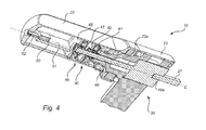
- the handle 20 has a sensor body 22 and a rotator sleeve 23 which are both rotatably connected to the shaft 21 around the longitudinal axis C.
- the rotator sleeve has a grip portion and is intended to be used by a user to rotate the instrument 10.
- rotation of the instrument 10 here means rotation of the rotator sleeve with respect to the shaft.
- the sleeve 23 and the sensor body 22 are preferably coupled by a certain friction, such that the sensor body will rotate with the rotator sleeve unless subject to external force.
- Reference numeral 40 denotes a first rotation sensor, such as an optic or magnetic sensor, which is mounted in the sensor body 22.
- the first sensor 40 has an encoding member 41, here a disc, and an encoder 42. Relative rotation of the encoder 42 in relation to the disc 41 can be detected, and results in a sensor signal indicative of the rotation.
- the first sensor 40 is here in electric contact with circuitry 50 on a printed circuit board 51, from which the sensor signal can be outputted via a signal interface 52.
- the encoder 42 is fixedly attached to the sensor body 22.
- the disc 41 is rotationally fixed to the rotator sleeve 23, here by means of a part 23a of the sleeve 23 extending partly into the sensor body 22. Rotation of the sleeve 23 in relation to the sensor body 22 will thus rotate the disc 41 in relation to the encoder 42, and generate a first detection signal available at the signal interface 52.
- the arrangement here comprises a second rotation sensor 46, arranged outside the first sensor 40 with respect to the sleeve 23.
- the second sensor 46 also has a code disc 47 and a encoder 48.
- the encoder 48 is fixedly arranged in the sensor body 22.
- the disc 47 is rotationally connected to a torque transfer member 49, arranged coaxially inside the part 23a along the longitudinal axis C of the handle.
- the member 49 thus extends past the first encoder 40 out of the sensor body 22 and further through the rotator sleeve 23. At its distal end 49a the member 49 is rotationally connected to the rigid shaft 21.
- rotation of the instrument 10 should rotate the field of view displayed on the display 4.
- rotation of the instrument will correspond to rotation of the sleeve 23 (which has the grip portion) with respect to the shaft 21.
- Relative rotation between the sleeve 23 and the shaft 21 may be retrieved by combining information from the first detection signal from the first sensor 40 (corresponding to relative rotation between the sleeve 23 and the shaft 21) and the second detection signal from the second rotation sensor 46 (corresponding to relative rotation between the sensor body 22 and the shaft 21).
- the sensor body 22 and rotator sleeve 23 are preferably coupled by a certain friction, so that they are normally rotated together.
- Such handle rotation will result in identical signals from the first sensor 40 and the second sensor 46.
- the combination of the sensor signals may be provided by the circuitry 50.
- the first and second sensor signals are provided unaltered to the processing unit 3, and the combination is provided there.
- An actual camera instrument also has the functionality to rotate the image sensor with respect to the instrument, in order to rotate the view rendered on the display 4 essentially without changing the field of view.
- the camera interface 1 simulation of such image sensor adjustment may be provided by detecting relative rotation of the sensor body 22 in relation to the sleeve 23. Such rotation is detected directly by the first sensor 40.
- reference 53 indicates an example embodiment of the touch sensitive user interfaces.
- the illustrated user interface 53 has four buttons 54 which are used to control features in the simulation system such as locking the user interface 1, so that the surgical simulation system 2 no longer registers input from the user interface 1 allowing the user to release the interface and to concentrate on other instruments.
- the other buttons on the user interface 53 may for example control features such as simulated zoom and focus for the image shown on the display 4.
- the user interface 53 is in electric contact with the circuitry 50 on the printed circuit board 51, from which the input signal can be outputted via a signal interface 52.
- buttons are by no means limited to this embodiment, further possibilities include a single button or for example a touch sensitive display, which may dynamically display any number of areas representative of functions or menus on the surgical simulation system 2.
- the circuitry 50 on the printed circuit board 51 may be capable of converting analog signals from the first sensor 40 and the second sensor 46 to digital signals.
- the circuitry 50 may be adapted to convert the analog signals to provide signals that are representative of the rotation of rotator sleeve 23 relative the shaft 21 and the rotation of sensor body 22 relative the shaft respectively.
- the circuitry 50 may also convert digital signals from the user interface 53.
- the circuitry 50 is adapted to convert the signals to a digital data signal compliant with USB standards.
- the interface 52 is here connected to the processing unit 3 via a signal line 55 (see figure 1 ).
- the connection may alternatively be wireless, e.g. Bluetooth or WiFi.
Landscapes
- Engineering & Computer Science (AREA)
- General Physics & Mathematics (AREA)
- Physics & Mathematics (AREA)
- Health & Medical Sciences (AREA)
- Mathematical Analysis (AREA)
- Pure & Applied Mathematics (AREA)
- Medical Informatics (AREA)
- Medicinal Chemistry (AREA)
- Chemical & Material Sciences (AREA)
- Algebra (AREA)
- Computational Mathematics (AREA)
- Theoretical Computer Science (AREA)
- Educational Technology (AREA)
- Mathematical Optimization (AREA)
- Mathematical Physics (AREA)
- General Health & Medical Sciences (AREA)
- Business, Economics & Management (AREA)
- Educational Administration (AREA)
- Radiology & Medical Imaging (AREA)
- Pulmonology (AREA)
- Nuclear Medicine, Radiotherapy & Molecular Imaging (AREA)
- Studio Devices (AREA)
- Position Input By Displaying (AREA)
- Measuring And Recording Apparatus For Diagnosis (AREA)
- Endoscopes (AREA)
Priority Applications (5)
| Application Number | Priority Date | Filing Date | Title |
|---|---|---|---|
| EP13171086.5A EP2811479B1 (fr) | 2013-06-07 | 2013-06-07 | Interface utilisateur pour un système de simulation d'opération chirurgicale |
| CN201480031503.3A CN105378819A (zh) | 2013-06-07 | 2014-06-03 | 用于手术模拟系统的用户接口 |
| US14/895,410 US20160117956A1 (en) | 2013-06-07 | 2014-06-03 | A user interface for a surgical simulation system |
| PCT/EP2014/061428 WO2014195282A1 (fr) | 2013-06-07 | 2014-06-03 | Interface utilisateur pour système de simulation chirurgical |
| RU2015150179A RU2015150179A (ru) | 2013-06-07 | 2014-06-03 | Пользовательское интерфейсное устройство для системы хирургического моделирования |
Applications Claiming Priority (1)
| Application Number | Priority Date | Filing Date | Title |
|---|---|---|---|
| EP13171086.5A EP2811479B1 (fr) | 2013-06-07 | 2013-06-07 | Interface utilisateur pour un système de simulation d'opération chirurgicale |
Publications (2)
| Publication Number | Publication Date |
|---|---|
| EP2811479A1 true EP2811479A1 (fr) | 2014-12-10 |
| EP2811479B1 EP2811479B1 (fr) | 2017-08-02 |
Family
ID=48613452
Family Applications (1)
| Application Number | Title | Priority Date | Filing Date |
|---|---|---|---|
| EP13171086.5A Active EP2811479B1 (fr) | 2013-06-07 | 2013-06-07 | Interface utilisateur pour un système de simulation d'opération chirurgicale |
Country Status (5)
| Country | Link |
|---|---|
| US (1) | US20160117956A1 (fr) |
| EP (1) | EP2811479B1 (fr) |
| CN (1) | CN105378819A (fr) |
| RU (1) | RU2015150179A (fr) |
| WO (1) | WO2014195282A1 (fr) |
Families Citing this family (36)
| Publication number | Priority date | Publication date | Assignee | Title |
|---|---|---|---|---|
| CA2811235C (fr) | 2010-10-01 | 2020-03-10 | Applied Medical Resources Corporation | Dispositif d'apprentissage portatif pour laparoscopie |
| EP2769375B1 (fr) | 2011-10-21 | 2017-07-19 | Applied Medical Resources Corporation | Structure de tissu simulée pour entraînement chirurgical |
| AU2012358851B2 (en) | 2011-12-20 | 2016-08-11 | Applied Medical Resources Corporation | Advanced surgical simulation |
| EP2880647A1 (fr) | 2012-08-03 | 2015-06-10 | Applied Medical Resources Corporation | Agrafage simulé et ligature basée sur le champ énergétique pour une formation chirurgicale |
| JP2015532450A (ja) | 2012-09-26 | 2015-11-09 | アプライド メディカル リソーシーズ コーポレイション | 腹腔鏡処置のための外科訓練モデル |
| EP4276801A3 (fr) | 2012-09-27 | 2024-01-03 | Applied Medical Resources Corporation | Modèle d'entraînement chirurgical pour interventions laparoscopiques |
| US10679520B2 (en) | 2012-09-27 | 2020-06-09 | Applied Medical Resources Corporation | Surgical training model for laparoscopic procedures |
| CA3159450A1 (fr) | 2012-09-27 | 2014-04-03 | Applied Medical Resources Corporation | Modele d'entrainement aux procedures chirurgicales laparoscopiques |
| CA2885326A1 (fr) | 2012-09-28 | 2014-04-03 | Applied Medical Resources Corporation | Maquette de formation chirurgicale pour interventions laparoscopiques |
| EP3467805B1 (fr) | 2012-09-28 | 2020-07-08 | Applied Medical Resources Corporation | Modèle d'apprentissage chirurgical pour des interventions laparoscopiques transluminales |
| EP2738756A1 (fr) * | 2012-11-30 | 2014-06-04 | Surgical Science Sweden AB | Dispositif d'interface utilisateur pour système de simulation d'opération chirurgicale |
| JP6482478B2 (ja) | 2013-03-01 | 2019-03-13 | アプライド メディカル リソーシーズ コーポレイション | 手術シミュレーションシステム及び方法 |
| JP6549100B2 (ja) | 2013-05-15 | 2019-07-24 | アプライド メディカル リソーシーズ コーポレイション | ヘルニア模型 |
| EP3011550B1 (fr) | 2013-06-18 | 2018-01-03 | Applied Medical Resources Corporation | Modèle de vésicule biliaire |
| US10198966B2 (en) | 2013-07-24 | 2019-02-05 | Applied Medical Resources Corporation | Advanced first entry model for surgical simulation |
| AU2014293036B2 (en) | 2013-07-24 | 2017-12-21 | Applied Medical Resources Corporation | First entry model |
| ES3048176T3 (en) | 2014-03-26 | 2025-12-09 | Applied Med Resources | Simulated dissectible tissue |
| CN105321415A (zh) * | 2014-08-01 | 2016-02-10 | 卓思生命科技有限公司 | 一种手术模拟系统及方法 |
| AU2015347077B2 (en) | 2014-11-13 | 2021-08-12 | Applied Medical Resources Corporation | Simulated tissue models and methods |
| KR102776500B1 (ko) | 2015-02-19 | 2025-03-06 | 어플라이드 메디컬 리소시스 코포레이션 | 시뮬레이션된 조직 구조체들 및 방법들 |
| CA2980776A1 (fr) | 2015-05-14 | 2016-11-17 | Applied Medical Resources Corporation | Structures de tissu synthetiques pour simulation et apprentissage d'electrochirurgie |
| US12512017B2 (en) | 2015-05-27 | 2025-12-30 | Applied Medical Resources Corporation | Surgical training model for laparoscopic procedures |
| KR20250165689A (ko) | 2015-06-09 | 2025-11-26 | 어플라이드 메디컬 리소시스 코포레이션 | 자궁 절제술 모델 |
| CN104952344A (zh) * | 2015-06-18 | 2015-09-30 | 青岛大学附属医院 | 一种神经外科虚拟手术训练系统 |
| CA3249585A1 (fr) | 2015-07-16 | 2025-02-24 | Applied Medical Resources Corporation | Tissu dissécable simulé |
| JP6862413B2 (ja) | 2015-07-22 | 2021-04-21 | アプライド メディカル リソーシーズ コーポレイション | 虫垂切除術用モデル |
| JP6916781B2 (ja) | 2015-10-02 | 2021-08-11 | アプライド メディカル リソーシーズ コーポレイション | 子宮摘出術用モデル |
| AU2016358076A1 (en) | 2015-11-20 | 2018-04-12 | Applied Medical Resources Corporation | Simulated dissectible tissue |
| US9754513B1 (en) * | 2016-02-26 | 2017-09-05 | Cae Healthcare Canada Inc. | Apparatus for simulating insertion of an elongated instrument into a structure including a pulley and a pulley position sensing arrangement |
| US20170249865A1 (en) * | 2016-02-26 | 2017-08-31 | Cae Healthcare Canada Inc. | Apparatus for simulating insertion of an elongated instrument into a structure providing axial rotating connection of the elongated instrument to a carriage |
| US10134306B2 (en) * | 2016-02-26 | 2018-11-20 | Cae Healthcare Canada Inc. | Apparatus for simulating insertion of an elongated instrument into a structure and medical insertion simulator |
| WO2018005301A1 (fr) | 2016-06-27 | 2018-01-04 | Applied Medical Resources Corporation | Paroi abdominale simulée |
| US10255828B2 (en) * | 2016-11-09 | 2019-04-09 | Stephen J. Snyder | Apparatus for releasably and adjustably mounting a tubular device to an object |
| ES3004046T3 (en) | 2017-02-14 | 2025-03-11 | Applied Med Resources | Laparoscopic training system |
| US10847057B2 (en) | 2017-02-23 | 2020-11-24 | Applied Medical Resources Corporation | Synthetic tissue structures for electrosurgical training and simulation |
| IT201700091381A1 (it) * | 2017-08-07 | 2019-02-07 | Vincenzo Cennamo | Periferica di comando per la simulazione di procedure endoscopiche. |
Citations (4)
| Publication number | Priority date | Publication date | Assignee | Title |
|---|---|---|---|---|
| GB2252656A (en) * | 1991-02-11 | 1992-08-12 | Keymed | Endoscopy training apparatus |
| WO1997019440A1 (fr) * | 1995-11-17 | 1997-05-29 | Immersion Human Interface Corporation | Procede et appareil permettant d'obtenir une force retroactive et un systeme entree/sortie mecanique d'un faible cout pour des systemes informatiques |
| WO2002037452A1 (fr) * | 2000-11-03 | 2002-05-10 | Karl Storz Gmbh & Co. Kg | Systeme de simulation comprenant au moins deux degres de liberte de deplacement pour un instrument |
| WO2009008750A1 (fr) * | 2007-07-12 | 2009-01-15 | Airway Limited | Simulateur d'endoscope |
Family Cites Families (43)
| Publication number | Priority date | Publication date | Assignee | Title |
|---|---|---|---|---|
| US6437771B1 (en) * | 1995-01-18 | 2002-08-20 | Immersion Corporation | Force feedback device including flexure member between actuator and user object |
| US6057828A (en) * | 1993-07-16 | 2000-05-02 | Immersion Corporation | Method and apparatus for providing force sensations in virtual environments in accordance with host software |
| US5767839A (en) * | 1995-01-18 | 1998-06-16 | Immersion Human Interface Corporation | Method and apparatus for providing passive force feedback to human-computer interface systems |
| US5731804A (en) * | 1995-01-18 | 1998-03-24 | Immersion Human Interface Corp. | Method and apparatus for providing high bandwidth, low noise mechanical I/O for computer systems |
| US5623582A (en) * | 1994-07-14 | 1997-04-22 | Immersion Human Interface Corporation | Computer interface or control input device for laparoscopic surgical instrument and other elongated mechanical objects |
| US6850222B1 (en) * | 1995-01-18 | 2005-02-01 | Immersion Corporation | Passive force feedback for computer interface devices |
| US5762255A (en) * | 1996-02-20 | 1998-06-09 | Richard-Allan Medical Industries, Inc. | Surgical instrument with improvement safety lockout mechanisms |
| US7815436B2 (en) * | 1996-09-04 | 2010-10-19 | Immersion Corporation | Surgical simulation interface device and method |
| US6929481B1 (en) * | 1996-09-04 | 2005-08-16 | Immersion Medical, Inc. | Interface device and method for interfacing instruments to medical procedure simulation systems |
| US6024576A (en) * | 1996-09-06 | 2000-02-15 | Immersion Corporation | Hemispherical, high bandwidth mechanical interface for computer systems |
| IL123073A0 (en) * | 1998-01-26 | 1998-09-24 | Simbionix Ltd | Endoscopic tutorial system |
| JP2002502058A (ja) * | 1998-01-28 | 2002-01-22 | エイチティー メディカル システムズ,インコーポレイティド | 血管アクセスシミレーションシステムへの器具の接続のためのインターフェース装置及び方法 |
| US6377011B1 (en) * | 2000-01-26 | 2002-04-23 | Massachusetts Institute Of Technology | Force feedback user interface for minimally invasive surgical simulator and teleoperator and other similar apparatus |
| DE10055294C2 (de) * | 2000-11-03 | 2002-10-31 | Storz Karl Gmbh & Co Kg | Simulatorvorrichtung mit zumindest zwei Bewegungsfreiheitsgraden für die Verwendung bei einem realen Instrument |
| SE518252C2 (sv) * | 2001-01-24 | 2002-09-17 | Goeteborg University Surgical | Metod för simulering av ett kirurgiskt moment, metod för simulering av kirurgisk operation och system för simulering av ett kirurgiskt moment |
| CN101344997A (zh) * | 2001-07-16 | 2009-01-14 | 伊梅森公司 | 具有缆绳驱动的力反馈和四个接地致动器的接口装置 |
| US7056123B2 (en) * | 2001-07-16 | 2006-06-06 | Immersion Corporation | Interface apparatus with cable-driven force feedback and grounded actuators |
| US20070166682A1 (en) * | 2003-01-22 | 2007-07-19 | Realsim Systems, Llc. | Medical training apparatus |
| CN100498873C (zh) * | 2003-03-26 | 2009-06-10 | 独立行政法人产业技术综合研究所 | 人体模型及其制造方法 |
| US20070018958A1 (en) * | 2003-10-24 | 2007-01-25 | Tavakoli Seyed M | Force reflective robotic control system and minimally invasive surgical device |
| US20060084050A1 (en) * | 2004-01-12 | 2006-04-20 | Haluck Randy S | Portable virtual reality medical demonstration and training apparatus |
| US8403674B2 (en) * | 2004-03-23 | 2013-03-26 | Laerdal Medical As | Vascular-access simulation system with ergonomic features |
| US20080278448A1 (en) * | 2005-03-30 | 2008-11-13 | Jonas Nilsagard | Control Device |
| US9579088B2 (en) * | 2007-02-20 | 2017-02-28 | Board Of Regents Of The University Of Nebraska | Methods, systems, and devices for surgical visualization and device manipulation |
| KR101218689B1 (ko) * | 2006-08-25 | 2013-01-04 | 각코호진 니혼시카다이가쿠 | 의료용 실습장치 |
| CN201215653Y (zh) * | 2008-01-07 | 2009-04-01 | 陈为坚 | 一种立体定位式鼠标器 |
| CN201156345Y (zh) * | 2008-01-10 | 2008-11-26 | 傅强 | 内窥镜微创手术仿真系统 |
| JP2009236963A (ja) * | 2008-03-25 | 2009-10-15 | Panasonic Electric Works Co Ltd | 内視鏡手術用トレーニング装置、内視鏡手術用技能評価方法 |
| CN101261781B (zh) * | 2008-05-08 | 2010-06-02 | 上海交通大学 | 五自由度力反馈虚拟手术器械 |
| JP5614980B2 (ja) * | 2009-12-25 | 2014-10-29 | 三菱プレシジョン株式会社 | トロカー位置設定用模擬術具位置設定装置 |
| US8764448B2 (en) * | 2010-09-01 | 2014-07-01 | Agency For Science, Technology And Research | Robotic device for use in image-guided robot assisted surgical training |
| CN102254476B (zh) * | 2011-07-18 | 2014-12-10 | 广州赛宝联睿信息科技有限公司 | 内窥镜微创手术模拟训练方法及其系统 |
| US9439668B2 (en) * | 2012-04-09 | 2016-09-13 | Ethicon Endo-Surgery, Llc | Switch arrangements for ultrasonic surgical instruments |
| CN202563792U (zh) * | 2012-05-17 | 2012-11-28 | 北京日正华瑞科技发展有限公司 | 基础腹腔镜模拟器 |
| CN202615697U (zh) * | 2012-06-01 | 2012-12-19 | 苏州敏行医学信息技术有限公司 | 基于力反馈的腹腔镜手术模拟系统 |
| US9510891B2 (en) * | 2012-06-26 | 2016-12-06 | Covidien Lp | Surgical instruments with structures to provide access for cleaning |
| US9198714B2 (en) * | 2012-06-29 | 2015-12-01 | Ethicon Endo-Surgery, Inc. | Haptic feedback devices for surgical robot |
| CN202795881U (zh) * | 2012-09-06 | 2013-03-13 | 佛山市金天皓科技有限公司 | 神经内镜虚拟手术培训系统人机操作接口装置 |
| CN202871171U (zh) * | 2012-09-06 | 2013-04-10 | 佛山市金天皓科技有限公司 | 神经内镜仿真模拟训练装置及其系统 |
| GB201217905D0 (en) * | 2012-10-05 | 2012-11-21 | Imp Innovations Ltd | A device |
| CN103106831A (zh) * | 2013-03-04 | 2013-05-15 | 合肥德易电子有限公司 | 一种内腔体微创手术训练操作装置 |
| JP6091410B2 (ja) * | 2013-12-26 | 2017-03-08 | オリンパス株式会社 | 内視鏡装置の作動方法及び内視鏡システム |
| US10292779B2 (en) * | 2015-11-23 | 2019-05-21 | Sina Robotics And Medical Innovators Co. | Adapting manual laparoscopic surgical instruments for robotic telesurgery applications |
-
2013
- 2013-06-07 EP EP13171086.5A patent/EP2811479B1/fr active Active
-
2014
- 2014-06-03 RU RU2015150179A patent/RU2015150179A/ru not_active Application Discontinuation
- 2014-06-03 CN CN201480031503.3A patent/CN105378819A/zh active Pending
- 2014-06-03 WO PCT/EP2014/061428 patent/WO2014195282A1/fr not_active Ceased
- 2014-06-03 US US14/895,410 patent/US20160117956A1/en not_active Abandoned
Patent Citations (4)
| Publication number | Priority date | Publication date | Assignee | Title |
|---|---|---|---|---|
| GB2252656A (en) * | 1991-02-11 | 1992-08-12 | Keymed | Endoscopy training apparatus |
| WO1997019440A1 (fr) * | 1995-11-17 | 1997-05-29 | Immersion Human Interface Corporation | Procede et appareil permettant d'obtenir une force retroactive et un systeme entree/sortie mecanique d'un faible cout pour des systemes informatiques |
| WO2002037452A1 (fr) * | 2000-11-03 | 2002-05-10 | Karl Storz Gmbh & Co. Kg | Systeme de simulation comprenant au moins deux degres de liberte de deplacement pour un instrument |
| WO2009008750A1 (fr) * | 2007-07-12 | 2009-01-15 | Airway Limited | Simulateur d'endoscope |
Also Published As
| Publication number | Publication date |
|---|---|
| RU2015150179A (ru) | 2017-07-14 |
| CN105378819A (zh) | 2016-03-02 |
| EP2811479B1 (fr) | 2017-08-02 |
| WO2014195282A1 (fr) | 2014-12-11 |
| US20160117956A1 (en) | 2016-04-28 |
Similar Documents
| Publication | Publication Date | Title |
|---|---|---|
| EP2811479B1 (fr) | Interface utilisateur pour un système de simulation d'opération chirurgicale | |
| CN105009185B (zh) | 用于手术模拟系统的触觉用户界面装置 | |
| CN104823226B (zh) | 用于外科手术模拟系统的用户界面设备 | |
| CN100559337C (zh) | 控制装置 | |
| US6104379A (en) | Forearm-supported exoskeleton hand-tracking device | |
| ES2959758T3 (es) | Sistema de MMC de brazo articulado | |
| JP3487944B2 (ja) | 内視鏡装置 | |
| US8834171B2 (en) | Simulation system for training in endoscopic operations | |
| US20090299142A1 (en) | Operating device, monitor device, and capsule guiding system | |
| CN102872519A (zh) | 用于指示导管挠曲的系统 | |
| US20120251991A1 (en) | Peripheral Probe with Six Degrees of Freedom Plus Compressive Force Feedback | |
| GB2380594A (en) | Endoscopy simulation apparatus. | |
| Gerald et al. | Soft sensing and haptics for medical procedures | |
| CN115315341B (zh) | 一种装置 | |
| Pabon et al. | A data-glove with vibro-tactile stimulators for virtual social interaction and rehabilitation | |
| WO2009008750A1 (fr) | Simulateur d'endoscope | |
| EP2811478A1 (fr) | Interface utilisateur pour dispositif de simulation de caméra | |
| GB2426115A (en) | Endoscopic simulation system. | |
| US20060211917A1 (en) | Data generating device and endoscope system | |
| Maillard et al. | Instrumentation of a clinical colonoscope for surgical simulation | |
| EP4414969A1 (fr) | Ensemble endoscope, ensemble caméra endoscopique et dispositif d'endoscopie | |
| US11847267B2 (en) | Input device tracking systems | |
| Mannion et al. | Manipulation of an wide angle endoscope in minimally invasive robotic surgery and training | |
| Chakravarthy et al. | Design of an endoscopic haptic display system using an integrated ring-actuator | |
| Saggio et al. | Wireless sensory glove system developed for advanced human computer interface |
Legal Events
| Date | Code | Title | Description |
|---|---|---|---|
| PUAI | Public reference made under article 153(3) epc to a published international application that has entered the european phase |
Free format text: ORIGINAL CODE: 0009012 |
|
| 17P | Request for examination filed |
Effective date: 20130607 |
|
| AK | Designated contracting states |
Kind code of ref document: A1 Designated state(s): AL AT BE BG CH CY CZ DE DK EE ES FI FR GB GR HR HU IE IS IT LI LT LU LV MC MK MT NL NO PL PT RO RS SE SI SK SM TR |
|
| AX | Request for extension of the european patent |
Extension state: BA ME |
|
| R17P | Request for examination filed (corrected) |
Effective date: 20150526 |
|
| RBV | Designated contracting states (corrected) |
Designated state(s): AL AT BE BG CH CY CZ DE DK EE ES FI FR GB GR HR HU IE IS IT LI LT LU LV MC MK MT NL NO PL PT RO RS SE SI SK SM TR |
|
| GRAP | Despatch of communication of intention to grant a patent |
Free format text: ORIGINAL CODE: EPIDOSNIGR1 |
|
| INTG | Intention to grant announced |
Effective date: 20170227 |
|
| GRAS | Grant fee paid |
Free format text: ORIGINAL CODE: EPIDOSNIGR3 |
|
| GRAA | (expected) grant |
Free format text: ORIGINAL CODE: 0009210 |
|
| AK | Designated contracting states |
Kind code of ref document: B1 Designated state(s): AL AT BE BG CH CY CZ DE DK EE ES FI FR GB GR HR HU IE IS IT LI LT LU LV MC MK MT NL NO PL PT RO RS SE SI SK SM TR |
|
| REG | Reference to a national code |
Ref country code: CH Ref legal event code: EP Ref country code: AT Ref legal event code: REF Ref document number: 915274 Country of ref document: AT Kind code of ref document: T Effective date: 20170815 |
|
| REG | Reference to a national code |
Ref country code: IE Ref legal event code: FG4D |
|
| REG | Reference to a national code |
Ref country code: DE Ref legal event code: R096 Ref document number: 602013024275 Country of ref document: DE |
|
| REG | Reference to a national code |
Ref country code: NL Ref legal event code: MP Effective date: 20170802 |
|
| REG | Reference to a national code |
Ref country code: AT Ref legal event code: MK05 Ref document number: 915274 Country of ref document: AT Kind code of ref document: T Effective date: 20170802 |
|
| REG | Reference to a national code |
Ref country code: LT Ref legal event code: MG4D |
|
| PG25 | Lapsed in a contracting state [announced via postgrant information from national office to epo] |
Ref country code: NL Free format text: LAPSE BECAUSE OF FAILURE TO SUBMIT A TRANSLATION OF THE DESCRIPTION OR TO PAY THE FEE WITHIN THE PRESCRIBED TIME-LIMIT Effective date: 20170802 Ref country code: FI Free format text: LAPSE BECAUSE OF FAILURE TO SUBMIT A TRANSLATION OF THE DESCRIPTION OR TO PAY THE FEE WITHIN THE PRESCRIBED TIME-LIMIT Effective date: 20170802 Ref country code: HR Free format text: LAPSE BECAUSE OF FAILURE TO SUBMIT A TRANSLATION OF THE DESCRIPTION OR TO PAY THE FEE WITHIN THE PRESCRIBED TIME-LIMIT Effective date: 20170802 Ref country code: LT Free format text: LAPSE BECAUSE OF FAILURE TO SUBMIT A TRANSLATION OF THE DESCRIPTION OR TO PAY THE FEE WITHIN THE PRESCRIBED TIME-LIMIT Effective date: 20170802 Ref country code: NO Free format text: LAPSE BECAUSE OF FAILURE TO SUBMIT A TRANSLATION OF THE DESCRIPTION OR TO PAY THE FEE WITHIN THE PRESCRIBED TIME-LIMIT Effective date: 20171102 Ref country code: SE Free format text: LAPSE BECAUSE OF FAILURE TO SUBMIT A TRANSLATION OF THE DESCRIPTION OR TO PAY THE FEE WITHIN THE PRESCRIBED TIME-LIMIT Effective date: 20170802 Ref country code: AT Free format text: LAPSE BECAUSE OF FAILURE TO SUBMIT A TRANSLATION OF THE DESCRIPTION OR TO PAY THE FEE WITHIN THE PRESCRIBED TIME-LIMIT Effective date: 20170802 |
|
| PG25 | Lapsed in a contracting state [announced via postgrant information from national office to epo] |
Ref country code: RS Free format text: LAPSE BECAUSE OF FAILURE TO SUBMIT A TRANSLATION OF THE DESCRIPTION OR TO PAY THE FEE WITHIN THE PRESCRIBED TIME-LIMIT Effective date: 20170802 Ref country code: IS Free format text: LAPSE BECAUSE OF FAILURE TO SUBMIT A TRANSLATION OF THE DESCRIPTION OR TO PAY THE FEE WITHIN THE PRESCRIBED TIME-LIMIT Effective date: 20171202 Ref country code: PL Free format text: LAPSE BECAUSE OF FAILURE TO SUBMIT A TRANSLATION OF THE DESCRIPTION OR TO PAY THE FEE WITHIN THE PRESCRIBED TIME-LIMIT Effective date: 20170802 Ref country code: BG Free format text: LAPSE BECAUSE OF FAILURE TO SUBMIT A TRANSLATION OF THE DESCRIPTION OR TO PAY THE FEE WITHIN THE PRESCRIBED TIME-LIMIT Effective date: 20171102 Ref country code: LV Free format text: LAPSE BECAUSE OF FAILURE TO SUBMIT A TRANSLATION OF THE DESCRIPTION OR TO PAY THE FEE WITHIN THE PRESCRIBED TIME-LIMIT Effective date: 20170802 Ref country code: GR Free format text: LAPSE BECAUSE OF FAILURE TO SUBMIT A TRANSLATION OF THE DESCRIPTION OR TO PAY THE FEE WITHIN THE PRESCRIBED TIME-LIMIT Effective date: 20171103 Ref country code: ES Free format text: LAPSE BECAUSE OF FAILURE TO SUBMIT A TRANSLATION OF THE DESCRIPTION OR TO PAY THE FEE WITHIN THE PRESCRIBED TIME-LIMIT Effective date: 20170802 |
|
| PG25 | Lapsed in a contracting state [announced via postgrant information from national office to epo] |
Ref country code: CZ Free format text: LAPSE BECAUSE OF FAILURE TO SUBMIT A TRANSLATION OF THE DESCRIPTION OR TO PAY THE FEE WITHIN THE PRESCRIBED TIME-LIMIT Effective date: 20170802 Ref country code: RO Free format text: LAPSE BECAUSE OF FAILURE TO SUBMIT A TRANSLATION OF THE DESCRIPTION OR TO PAY THE FEE WITHIN THE PRESCRIBED TIME-LIMIT Effective date: 20170802 Ref country code: DK Free format text: LAPSE BECAUSE OF FAILURE TO SUBMIT A TRANSLATION OF THE DESCRIPTION OR TO PAY THE FEE WITHIN THE PRESCRIBED TIME-LIMIT Effective date: 20170802 |
|
| REG | Reference to a national code |
Ref country code: DE Ref legal event code: R097 Ref document number: 602013024275 Country of ref document: DE |
|
| REG | Reference to a national code |
Ref country code: FR Ref legal event code: PLFP Year of fee payment: 6 |
|
| PG25 | Lapsed in a contracting state [announced via postgrant information from national office to epo] |
Ref country code: SK Free format text: LAPSE BECAUSE OF FAILURE TO SUBMIT A TRANSLATION OF THE DESCRIPTION OR TO PAY THE FEE WITHIN THE PRESCRIBED TIME-LIMIT Effective date: 20170802 Ref country code: EE Free format text: LAPSE BECAUSE OF FAILURE TO SUBMIT A TRANSLATION OF THE DESCRIPTION OR TO PAY THE FEE WITHIN THE PRESCRIBED TIME-LIMIT Effective date: 20170802 Ref country code: IT Free format text: LAPSE BECAUSE OF FAILURE TO SUBMIT A TRANSLATION OF THE DESCRIPTION OR TO PAY THE FEE WITHIN THE PRESCRIBED TIME-LIMIT Effective date: 20170802 Ref country code: SM Free format text: LAPSE BECAUSE OF FAILURE TO SUBMIT A TRANSLATION OF THE DESCRIPTION OR TO PAY THE FEE WITHIN THE PRESCRIBED TIME-LIMIT Effective date: 20170802 |
|
| PLBE | No opposition filed within time limit |
Free format text: ORIGINAL CODE: 0009261 |
|
| STAA | Information on the status of an ep patent application or granted ep patent |
Free format text: STATUS: NO OPPOSITION FILED WITHIN TIME LIMIT |
|
| 26N | No opposition filed |
Effective date: 20180503 |
|
| PG25 | Lapsed in a contracting state [announced via postgrant information from national office to epo] |
Ref country code: SI Free format text: LAPSE BECAUSE OF FAILURE TO SUBMIT A TRANSLATION OF THE DESCRIPTION OR TO PAY THE FEE WITHIN THE PRESCRIBED TIME-LIMIT Effective date: 20170802 |
|
| REG | Reference to a national code |
Ref country code: DE Ref legal event code: R119 Ref document number: 602013024275 Country of ref document: DE |
|
| REG | Reference to a national code |
Ref country code: CH Ref legal event code: PL |
|
| REG | Reference to a national code |
Ref country code: BE Ref legal event code: MM Effective date: 20180630 |
|
| REG | Reference to a national code |
Ref country code: IE Ref legal event code: MM4A |
|
| PG25 | Lapsed in a contracting state [announced via postgrant information from national office to epo] |
Ref country code: LU Free format text: LAPSE BECAUSE OF NON-PAYMENT OF DUE FEES Effective date: 20180607 Ref country code: MC Free format text: LAPSE BECAUSE OF FAILURE TO SUBMIT A TRANSLATION OF THE DESCRIPTION OR TO PAY THE FEE WITHIN THE PRESCRIBED TIME-LIMIT Effective date: 20170802 |
|
| PG25 | Lapsed in a contracting state [announced via postgrant information from national office to epo] |
Ref country code: CH Free format text: LAPSE BECAUSE OF NON-PAYMENT OF DUE FEES Effective date: 20180630 Ref country code: DE Free format text: LAPSE BECAUSE OF NON-PAYMENT OF DUE FEES Effective date: 20190101 Ref country code: LI Free format text: LAPSE BECAUSE OF NON-PAYMENT OF DUE FEES Effective date: 20180630 Ref country code: IE Free format text: LAPSE BECAUSE OF NON-PAYMENT OF DUE FEES Effective date: 20180607 |
|
| PG25 | Lapsed in a contracting state [announced via postgrant information from national office to epo] |
Ref country code: BE Free format text: LAPSE BECAUSE OF NON-PAYMENT OF DUE FEES Effective date: 20180630 |
|
| PG25 | Lapsed in a contracting state [announced via postgrant information from national office to epo] |
Ref country code: MT Free format text: LAPSE BECAUSE OF NON-PAYMENT OF DUE FEES Effective date: 20180607 |
|
| PG25 | Lapsed in a contracting state [announced via postgrant information from national office to epo] |
Ref country code: TR Free format text: LAPSE BECAUSE OF FAILURE TO SUBMIT A TRANSLATION OF THE DESCRIPTION OR TO PAY THE FEE WITHIN THE PRESCRIBED TIME-LIMIT Effective date: 20170802 |
|
| PG25 | Lapsed in a contracting state [announced via postgrant information from national office to epo] |
Ref country code: PT Free format text: LAPSE BECAUSE OF FAILURE TO SUBMIT A TRANSLATION OF THE DESCRIPTION OR TO PAY THE FEE WITHIN THE PRESCRIBED TIME-LIMIT Effective date: 20170802 Ref country code: HU Free format text: LAPSE BECAUSE OF FAILURE TO SUBMIT A TRANSLATION OF THE DESCRIPTION OR TO PAY THE FEE WITHIN THE PRESCRIBED TIME-LIMIT; INVALID AB INITIO Effective date: 20130607 |
|
| PG25 | Lapsed in a contracting state [announced via postgrant information from national office to epo] |
Ref country code: MK Free format text: LAPSE BECAUSE OF NON-PAYMENT OF DUE FEES Effective date: 20170802 Ref country code: CY Free format text: LAPSE BECAUSE OF FAILURE TO SUBMIT A TRANSLATION OF THE DESCRIPTION OR TO PAY THE FEE WITHIN THE PRESCRIBED TIME-LIMIT Effective date: 20170802 |
|
| PG25 | Lapsed in a contracting state [announced via postgrant information from national office to epo] |
Ref country code: AL Free format text: LAPSE BECAUSE OF FAILURE TO SUBMIT A TRANSLATION OF THE DESCRIPTION OR TO PAY THE FEE WITHIN THE PRESCRIBED TIME-LIMIT Effective date: 20170802 |
|
| PGFP | Annual fee paid to national office [announced via postgrant information from national office to epo] |
Ref country code: GB Payment date: 20250515 Year of fee payment: 13 |
|
| PGFP | Annual fee paid to national office [announced via postgrant information from national office to epo] |
Ref country code: FR Payment date: 20250515 Year of fee payment: 13 |