EP2811601A2 - Kabelanschlusskasten - Google Patents
Kabelanschlusskasten Download PDFInfo
- Publication number
- EP2811601A2 EP2811601A2 EP14171057.4A EP14171057A EP2811601A2 EP 2811601 A2 EP2811601 A2 EP 2811601A2 EP 14171057 A EP14171057 A EP 14171057A EP 2811601 A2 EP2811601 A2 EP 2811601A2
- Authority
- EP
- European Patent Office
- Prior art keywords
- cable
- housing wall
- box
- connection box
- housing
- Prior art date
- Legal status (The legal status is an assumption and is not a legal conclusion. Google has not performed a legal analysis and makes no representation as to the accuracy of the status listed.)
- Granted
Links
- 238000009434 installation Methods 0.000 description 14
- 210000004907 gland Anatomy 0.000 description 6
- 238000011161 development Methods 0.000 description 5
- 230000018109 developmental process Effects 0.000 description 5
- 239000012212 insulator Substances 0.000 description 3
- 238000013021 overheating Methods 0.000 description 3
- 238000010276 construction Methods 0.000 description 2
- 238000013461 design Methods 0.000 description 2
- 230000000694 effects Effects 0.000 description 2
- 238000010438 heat treatment Methods 0.000 description 2
- 230000006698 induction Effects 0.000 description 2
- 230000001939 inductive effect Effects 0.000 description 2
- 238000003780 insertion Methods 0.000 description 2
- 230000037431 insertion Effects 0.000 description 2
- 238000012423 maintenance Methods 0.000 description 2
- 238000005457 optimization Methods 0.000 description 2
- 230000001419 dependent effect Effects 0.000 description 1
- 239000000463 material Substances 0.000 description 1
- 230000009469 supplementation Effects 0.000 description 1
Images




Classifications
-
- H—ELECTRICITY
- H02—GENERATION; CONVERSION OR DISTRIBUTION OF ELECTRIC POWER
- H02G—INSTALLATION OF ELECTRIC CABLES OR LINES, OR OF COMBINED OPTICAL AND ELECTRIC CABLES OR LINES
- H02G3/00—Installations of electric cables or lines or protective tubing therefor in or on buildings, equivalent structures or vehicles
- H02G3/22—Installations of cables or lines through walls, floors or ceilings, e.g. into buildings
-
- H—ELECTRICITY
- H02—GENERATION; CONVERSION OR DISTRIBUTION OF ELECTRIC POWER
- H02G—INSTALLATION OF ELECTRIC CABLES OR LINES, OR OF COMBINED OPTICAL AND ELECTRIC CABLES OR LINES
- H02G15/00—Cable fittings
- H02G15/013—Sealing means for cable inlets
-
- H—ELECTRICITY
- H02—GENERATION; CONVERSION OR DISTRIBUTION OF ELECTRIC POWER
- H02B—BOARDS, SUBSTATIONS OR SWITCHING ARRANGEMENTS FOR THE SUPPLY OR DISTRIBUTION OF ELECTRIC POWER
- H02B1/00—Frameworks, boards, panels, desks, casings; Details of substations or switching arrangements
- H02B1/26—Casings; Parts thereof or accessories therefor
- H02B1/30—Cabinet-type casings; Parts thereof or accessories therefor
- H02B1/305—Cable entries
Definitions
- the invention relates to a cable junction box.
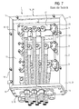
- Such a cable connection box (in the following only short terminal box), for example, for an electrical connection of a generator system of a wind turbine (short here only generator junction box) to a consumer / customer, as known from the prior art and exemplified in FIG. 7 shown comprises a substantially cuboid or box-shaped (cable box) housing.
- the housing consists of a total of six plate-like or planar, usually interconnected or screwed (Kabelan gleichkastengeoph) walls which surround a substantially cuboid housing interior of the cable box with local (cable) connection elements and their two each via a common Edge (between these two walls) connect to each other.
- These six walls are a (housing) rear wall, a rear panel opposite, usually removable front panel or openable cable junction box door / door (not in FIG. 7 shown), a (housing) bottom plate / - wall, a bottom plate / wall opposite (housing) cover plate / wall and two opposite (housing) side walls.
- the front panel of the housing is usually removable or the cable connection box opening door / flap of the housing is openable, whereby access, for example, for assembly, installation and / or maintenance, the housing interior of the housing is obtained.
- FIG. 7 shows, arranged a step support plate, which has three formed at different depths, vertically stacked support stages - for connecting cables - has.
- a relative to the stepped support plate by insulators insulated, horizontally aligned, conductive shift rail (for each phase of a three-phase alternating current) is arranged.
- FIG. 7 shows, in each case a plurality of input cables / strands, eg, generator strands, to a plurality of output or connection cables / strands, eg consumer / customer strands, connected - and thus provide the electrical connection, for example, the generator system of the wind turbine to or to the consumer , her.
- a plurality of input cables / strands eg, generator strands
- a plurality of output or connection cables / strands eg consumer / customer strands
- the input strands are doing, like FIG. 7 shows, guided through through holes or through holes in the rear wall of the housing in this - and are tightly bundled there by means of cable lugs bolted to the respective shift rail.
- the connecting cables enter the housing "from below”.
- the bottom plate also cable guide plate
- openings screw screw (cable glands)
- the connection cables are guided ("threaded") in the housing - and there also tightly bundled by means of cable lugs bolted to the respective shift rail.
- connection cables When carrying out the connection cable through the cable gland, the connection cables can be screwed into "their" respective cable gland, whereby the connecting cables within the housing are strain-relieved / -bar.
- the input strands or generator strands are to be routed through the respective openings in the rear wall and then also screwed to the respective shift rail.
- the front panel of the terminal box housing can then be replaced or the cable connection box opening door / flap of the terminal box housing can then be closed again, whereby the terminal box is fully assembled / connected.
- connection box for example, for a generator installation of a wind power plant - and if such a generator connection box is arranged in a nacelle of the wind power installation, then the installation or the cable connection, in particular the cable connection of the connection cable or generator connection cable, requires a not inconsiderable expenditure of force the connection cables at the cable connection against their - not insignificant - its own weight "up” (in the nacelle) are pulled. In particular, when "threading from below" the generator connecting cable strength and skill is required.
- connection box requires not a small effort or effort and not small skills and experience must also here or must the connection cable here too elaborately “threaded from below” and is the screwing of the cable, ie the input strands and the connection cable, due to their dense and compact bundling at the respective Switching rail - not difficult to handle in confined indoor conditions in the connection box.
- the dense and compact bundling of cables in such junction boxes can or the more cables are used in such junction boxes, which consequently requires a compact and bundled cable management in the terminal box or, this can also to a heating of the cable, in particular the connection cable , and so in consequence of the junction box lead. Inductive and convective effects must also be taken into account, especially with such dense and compact cable bundles.
- additional costly and therefore cost intensive / driving safety precautions, such as additional shields are required in such junction boxes.
- the invention has for its object to improve the disadvantages of the prior art, in particular to allow easier installation of the junction box and the connection cable in the connection box, in particular of generator connection cable in a generator junction box.
- the invention is based on a cable junction box with a housing having at least one first housing wall, which has at least one passage for a cable, and with at least one second housing wall adjoining the first housing wall, via or through which the cable junction box can be opened - and thereby Access to an interior of the cable box is obtained.
- the lead-through is designed as a cutout provided in the first housing wall with a cut-out opening, which cut-out opening leads to the second, is directed to the first housing wall subsequent housing wall.
- the invention means "the second housing wall adjoining the first housing wall" of the cable connection box that the first and the second housing wall to each other - directly, for example via a "(immediate) common edge" in the first and the second housing wall or about (directly) opposite housing wall edges of the first and the second housing wall - or - indirectly, for example, only separated by a (removable) end strip between the first and the second housing wall or between the (then indirectly) opposite housing wall edges of the first and the second housing wall , connect.
- first and the second housing wall form a - direct or indirect - common edge - or a housing wall edge of the first housing wall closes - directly or indirectly - to a housing wall edge of the second housing wall.
- the invention with "the introduced in the first housing wall recess with recess opening” extending from an edge of the first housing wall "to the interior” extending material removal on the housing wall edge.
- the original housing wall edge of the first housing wall or the original housing wall edge of the first housing wall occurs - compared to its original course - "inwards” back - and thus releases the recess with the recess opening.
- the invention also means with "the second housing wall directed towards the recess opening of the recess in the first housing wall” that the recess opening is provided on that housing wall edge of the first housing wall, where the second housing wall to the first housing wall - directly or indirectly - connects or the first housing wall a - direct or indirect - common edge forms with the second housing wall.
- the recess is inventively not set to a specific shape, but can take any forms. For example, it may be rectangular. That is, the recess appears similar to a step in the first housing wall or in the housing wall edge / in the housing wall edge of the first housing wall. Also a curved, e.g. Semicircular or semi-elliptical, recess in the first housing wall or in the housing wall edge / the housing wall edge of the first housing wall is possible.
- a plurality of recesses in the first housing wall may also be formed, each directed with its recess openings towards the second housing wall.
- the invention provides - unlike the prior art with "lying inside cable box housing walls, thus bounded and thus threading through cables requiring bushings - a passage according to the invention - as recess with recess opening - at the edge of a cable box housing wall before - and indeed at this cable connection box housing wall or at this Jardinan gleichkastengephasewandrand, at which or at which an openable further cable junction box housing wall or its Jardinan gleichkastengephasewandrand - directly or indirectly - connects, so that - with another cable terminal box housing wall - the implementation of the invention or the recess in the cable junction box housing wall - whose opening opening - open / untouched on one side - and thus "freely accessible" - is.
- the invention thus allows by their inventive design of the first and second housing wall or the implementation / recess in the first housing wall, that - with open second housing wall - a cable connection or a cable mounting, for example, a screw of a cable to a cable connection element, such as a shift rail , Inside the cable junction box / housing by simply frontal "inserting" a cable into the recess - instead of "threading" a cable through an all-round edged implementation - is possible.
- the invention enables unobstructed frontal cable mounting / fitting in the cable junction box by simply inserting a cable into the recess of the first cable junction box wall with the second "front" cable junction box wall open.
- the invention thus provides a (constructively) simple and cost-effective solution for a simple and inexpensive cable assembly / cable connection in a - in particular difficult to access - cable box available.
- a simple assembly as made possible by the invention, reduces a number of assembly hours and thus leads to a cost-effective solution.
- the invention also makes it possible that existing, disadvantageous cable junction boxes from the prior art easily and inexpensively converted - and so on - can be changed only an existing implementation in a cable connection housing wall according to the invention or a new inventive implementation / recess in the cable connection housing wall be introduced.
- a tiered arrangement of cables i. or, for example, a stepped support plate with a plurality of connection stage stages and there-in particular via shift rails - screwed cables, is still available in the cable connection box according to the invention with its "frontal" mounting available.
- the invention makes it possible to place switching rails / cable connection rails next to one another in the cable connection box, whereby the otherwise dense and compact bundling of the cables / connection cables in the cable connection box can be reduced.
- the heating of the cables / connecting cables can be reduced, inductive and convective effects reduced. If necessary, previously or otherwise relevant additional, complex and therefore cost intensive / driving necessary safety precautions, such as additional shields can be omitted in the invention.
- the first housing wall has a plurality of bushings, which is in each case designed as a recess introduced in the first housing wall whose recess opening is directed to the second housing wall adjoining the first housing wall ("cable entries arranged side by side").
- the plurality of recesses are inserted in a comb-like manner next to one another in the first housing wall.
- the cables in particular the connection cables, can be "fanned out” and thus bundled less (in or in the cable connection box).
- Such fanned out, less bundled and with distance led cables / connecting cables can convect freely - and need not be protected against overheating.
- This space optimization in the cable connection box also saves costs by saving installation time and installation space.
- connection rail shift rail
- connection box at least one connection rail (shift rail) insulated with respect to the connection box is arranged in the connection box.
- This can be set up in such a way that the cable which can be inserted into the terminal box through the first housing wall can be screwed there, in particular that several cables which can be inserted into the terminal box through the first housing wall can be screwed there.
- the several cables which can be inserted through the first housing wall into the connection box are screwed next to one another there in a row.
- connection box provision can also be made for three such connecting bars, in particular in series next to one another, to be arranged in the connection box, which are each provided for a phase connection. Also, two or even more than three such connecting rails, in particular in series next to each other, may be arranged in the connection box.
- the cables By the side by side screwed to a connecting rail cables, in particular by the juxtaposed connecting rails with each side there screwed cable, the cables, in particular the connection cable, "fanned out” and thus less bundled (in or in the cable box) are performed. Such fanned out, less bundled and spaced cable / connection cables are free to convection - and do not need to be protected from overheating. This space optimization in the cable connection box also saves costs by saving installation time and installation space.
- connection bars arranged in the connection box these are arranged vertically one above the other.
- a step support plate with, in particular at different depths, vertically stacked Anschlußstestagissuen be provided in the connection box, at which Anschlußustrag stages the connecting rails - then staggered in vertical and optionally at different depths.
- At least one third housing wall is provided, which has further feedthroughs for cables, for example input or generator strands / cables, into the terminal box.
- the connecting rail or the connecting rails can then be set up in such a way that cables inserted into the terminal box through the third housing wall can likewise be screwed there, in particular in a row next to one another.
- a cable guide frame which is arranged to guide the cable, in particular a plurality of cables arranged in series next to one another in the cable guide frame.
- the cable guide frame can also be designed so that the cable or the cable is guided zugentlastend there or become.
- the cable guide frame can be arranged on the first housing wall in such a way that an opening of the cable guide frame is aligned with the recess (in the first housing wall), whereby the cable guide frame screwed in this state with the first housing wall forms a common recess with the recess Opening forms, through which the cable into the terminal box insertable, in particular zugentlastend insertable, is.
- a strip in particular an insulating strip, for example made of plastic, which is arranged between the first housing wall and the second housing wall in such a way that the recess opening is delimited by means of the strip.
- This bar can also be set up for a Schutzarterhellung. As a result, an induction between phase units, for example U, V, W, in particular in the cable entries arranged side by side can be canceled.
- the strip for example a plastic end strip, can be arranged over a length of a common edge between the first housing wall and the second housing wall between the first housing wall and the second housing wall.
- the first housing wall is a bottom plate (cable feed-through plate) and / or the second housing wall is a removable front plate or a cable connection box opening door / flap and / or the third housing wall is / are a (housing) rear wall.
- connection box is a generator connection box, in particular a wind power plant generator connection box arranged in a nacelle of a wind power plant.
- the connection box is a generator connection box, in particular a wind power plant generator connection box arranged in a nacelle of a wind power plant.
- the terminal box is a motor terminal box, in particular for the connection of electric motors to an electrical network, or a terminal box for other electrical consumers or producers to a network.
- the invention is not limited to the combination of features specified in the exemplary embodiments, not even with regard to functional features.
- suitable features of each embodiment can also be considered explicitly isolated, removed from one exemplary embodiment, introduced into another exemplary embodiment for its supplementation.
- connection cables generator and motor connection cables
- side-by-side switching rails FIGS. 1 . 2 and 3
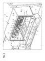
- FIGS. 1 . 2 and 3 show in - three - views each one (first) cable junction box 1 for the (electrical) connection of a generator of a wind turbine to an electrical distribution network (consumer / customer) (not shown).
- the cable junction box 1 is also suitable for other dynamoelectric machines, such as motors.
- the cable junction box 1 is mounted in a nacelle of the wind turbine (not shown).
- the cable junction box 1 or generator junction box 1 (also referred to below as junction box 1) has a substantially cuboidal or box-shaped (cable junction box) housing 2.
- This housing 2 comprises a total of six plate-like or planar, interconnected or screwed (Kabelan gleichkastengeoph) walls 18, which enclose a substantially cuboid housing interior 16 of the cable box 1 with there (cable) connection elements 17 and their two each over a common edge 19 (between these two walls 18) connect to each other.
- the six walls 18 of the junction box 1 are a (housing) rear wall 10, one of the rear wall 10 opposite, removable, multi-part - in this case, three-part - front panel 6 (see. FIG. 3 ), a (housing) bottom plate / wall 3, a bottom plate / wall 3 opposite (housing) cover plate / wall 20 and two opposite (housing) side walls 21st
- the three-part front panel 6 of the housing 2 is - like the FIGS. 1 and 2 (compared to FIG. 3 ) - detachable, whereby access for assembly, installation and / or maintenance of the housing interior 16 of the housing 2 of the junction box 1 can be obtained.
- the housing interior 16 of the junction box 1 is divided, as FIG. 1 shows, in three sections / departments 22, in each of which a certain number of cables 5 are connected.
- FIG. 1 and 2 show, three, ie in each compartment 22 of the housing 2 of the junction box 1 one, with respect to the housing 2 by insulators 23 isolated, horizontally oriented, side by side and slightly offset in vertical height, arranged conductive switching rails 9 (for each phase U, V , W of a three-phase alternating current).
- FIG. 1 and 2 show, in each case a plurality of input cables / strands 24 (5), ie generator strands 24 of the generator of the wind turbine, each to a plurality of output or connection cable / strands 25 (5), ie consumer / customer strands 25, connected - and so make the electrical connection of the generator of the wind turbine to or to the consumer.
- the input strands 24 (5) are doing, as FIG. 1 and 2 show, through through holes 4 and through holes 4 in the rear wall 10 of the housing 2 is guided in this - and are there bundled by means of cable lugs 26 and side by side with / on the (depending on their phase) respective shift rail 9 screwed.
- the generator-side connection of the connection box 1 is / is done so.
- FIG. 1 and 2 show, the bottom plate 3 of the housing 2 comb-like (ie in series next to each other), according to "front open", ie in the direction of the front panel 6 open, rectangular, in this case a total of six recesses 7 - with corresponding (six) recess openings eighth (for each four cables 5 or four of the connection cable / customer strands 25 (5)) - on.
- the width of such a recess 7 or its recess opening 8 is dimensioned such that a certain (specifiable) number of cables 5 (in this case four cables 5) there (in their "juxtaposition”) are unenforceable carried out / inserted.
- the recesses 7 are also each introduced into the bottom plate 3, that two - the total of six - recesses 7 are arranged vertically below a shift rail 9, whereby the shortest cable management of the connection cable / customer strands 25 (5) in the terminal box 1 (of the respective Base plate recess 7 to the respective shift rail 9) is guaranteed.
- the terminal box 1 thus allows by its design of its bottom plate 3 and the local open-front feedthroughs 4 / recesses 7, that - with open front panel 6 (see. FIG. 1 and 2 ) - the cable connection of the connecting cable 25 (5) or the customer strands 25 (5) - here four (number of connection cables / customer strands 25 (5) per recess 7) times two (number of recesses 7 per department 22 or shift rail 9 ) times three (number of compartments 22 or switching rails 9)
- Connecting cables / customer wires 25 (5), ie (in total) 24 connecting cables / customer wires 25 (5) - can be done in the recesses 7 to the shift rails 9 in the housing interior 16 of the junction box 1 by simply frontal "inserting" the connection cable 25 (5) or customer strands 25 (5).
- connection cables 25 (5) or customer strands 25 (5) are inserted "from the front" into the recesses 7, the connection cables 25 (5) or customer strands 25 (5) (like the generator strands 24 (5)) by means of cable lugs 26 bundled and side by side with / on the (depending on their phase U, V, W) respective shift rail 9 screwed.
- connection cables 25 (5) or the customer strands 25 thus enter the housing 2 "from below” into the housing 2 after their frontal mounting and when the front panel 3 is closed / closed (cf. FIG. 3 ).
- the connecting cable / customer strands 25 (5) and the input strands / generator strands 24 tightly bundled by means of the cable lugs 26 with the respective shift rail 9 are screwed (see. FIG. 1 ).
- junction box 1 The customer-side connection of the junction box 1 is accomplished so; the junction box 1 is connected.
- connection cable / customer strands 25 (5) are or will be provided by a cable guide frame 11 - thus in this case a total of six cable guide frames 11 for the total of 24 connection cables / customer strands 25 (5). bundled led.
- these cable guide frames 11 are each formed as a rectangular frame with two longitudinal parts 27 and two, with the longitudinal parts 27 screwed side panels 28. Within the cable guide frame 11, the respective four connecting cables / customer strands 25 (5) are separated or separated by separating webs 29.
- FIG. 1 illustrates the bundled connection cable / customer strands 25 (5), ie the four bundles including their cable guide frame 11 inserted from the front into the recesses 7.
- connection cables / customer strands 25 (5) are screwed by means of the cable lugs 26 to the shift rails 9; the cable guide frames 11 are so screwed (inside the housing 16) with the bottom plate 3 of the housing 2, that the openings 12 are aligned with the recesses 7, whereby the screwed in this state with the bottom plate 3 cable guide frame 11 with the recesses 7 common through holes 13th for the (bundled) connection cables / customer strands 25 (5).
- the (screwed) cable guide frame 11 are used simultaneously (four-bundle / bundled guide) for strain relief of the connection cable / customer strands 25 (5) in the terminal box. 1
- connection cable / customer wires 25 screwed to the shift rails 9 and the cable guide frame 11 to the recesses 7 and to the bottom plate 3, as FIG. 1 also shows the recesses 8 by means of a plastic strip 14 - along the common edge 15 between the bottom plate 3 and front panel 6 - covered.
- This plastic strip 14 is used for Schutzarterhellung and lifts the induction between the phases U, V, W of the departments 22 and in this respect juxtaposed connection cable / customer strands 25 (5).
- this plastic strip 14 is along the recesses 7 and recess openings 8 having edge / edge 30 of the bottom plate 3 over the entire (Bodenplatten-) width arranged / screwed and thus covers the recesses 7 and the recess openings 8 - along the entire Edge 30 the bottom plate 3 and the entire common edge 15 of the bottom plate 3 and front panel 6 from.
- connection box 1 can - after screwing the connection cable / customer wires 25 (5) to the shift rails 9, the cable guide frame 11 on the recesses 7 and on the bottom plate 3 and the plastic strip 14 on the edge 30 of the bottom plate 3 - by placing and fastening the front panel 6 on the housing 2 are closed again.
- junction box 1 thus allows an unobstructed, frontal cable mounting / connection or screw in the junction box 1 by simply inserting the connection cable 25 (5) or customer strands 25 (5) in the recesses 7 of the bottom plate 3 with open front panel 6 "from the front ".
- the (screwed) cable 5 are so "fanned" so less bundled (as circular cable bundles) and at a distance led that the cable 5 or in particular the connection cable / customer strands 25 (5) can freely convect - and not against overheating (by means of appropriate protection elements) must be protected.
- This junction box 1 with its so given possibility of frontal (cable) mounting, its optimized cable management in its housing interior 16 and its (thereby also) optimized space overall and its possibility given by waiving / saving additional protection elements thus saves costs - by his Savings on assembly time, (additional) components and installation space.
- connection cables generator and motor connection cables
- step plate vertically one above the other arranged shift rails
- FIGS. 4 . 5 and 6 each show in their respective views a (second) cable junction box 1 for the (electrical) connection of the wind turbine generator.
- the (second) cable connection box 1 after the FIGS. 4 . 5 and 6 is functionally and substantially identical in construction / construction to the cable junction box 1 according to the FIGS. 1 . 2 and 3 .
- Related statements to the (first) cable junction box 1 after the FIGS. 1 . 2 and 3 thus apply to the (second) cable junction box 1 after the FIGS. 4 . 5 and 6 corresponding.
- FIGS. 4 . 5 and 6 - compared to the FIGS. 1 . 2 and 3 - show the major structural difference between these two cable box 1 after the FIGS. 1 . 2 and 3 respectively.
- the three shift rails 9 (for each phase a shift rail 9) - screwed on the insulators 23 on a arranged on the rear wall 10 step plate (not visible) with three vertical and formed at different depths support levels - vertically above one another and in different Depth in the cable box 1 is arranged.
- Cable guide or cable connection is otherwise according to the cable connection box 1 after the FIGS. 1 . 2 and 3 or adapted to the vertical and arranged at different depths shift rails 9 executed.
- FIGS. 4 . 5 and 6 show is in local cable box 1, the recesses 7 having bottom plate 3 is withdrawn in depth, ie less deep; in return, the plastic rail 14 is at the cable junction box 1 widened in depth, but here also covers the recesses 7 and the recess openings 8 along the entire edge 30 of the bottom plate 3 from.
- connection box 1 after the FIGS. 4 . 5 and 6 allows an unobstructed, frontal cable mounting / connection or -Verschraubung in the terminal box 1 by simply inserting the connection cable 25 (5) or customer strands 25 (5) in the recesses 7 of the bottom plate 3 (with open front panel) "from the front".
Landscapes
- Engineering & Computer Science (AREA)
- Architecture (AREA)
- Civil Engineering (AREA)
- Structural Engineering (AREA)
- Installation Of Indoor Wiring (AREA)
- Connection Or Junction Boxes (AREA)
Abstract
Description
- Die Erfindung betrifft einen Kabelanschlusskasten.
- Ein solcher Kabelanschlusskasten (auch im Folgenden kurz nur Anschlusskasten), beispielsweise für einen elektrischen Anschluss einer Generatoranlage einer Windkraftanlage (kurz hier nur Generatoranschlusskasten) an einen Verbraucher/Kunden, wie aus dem Stand der Technik bekannt und beispielhaft in
FIG 7 dargestellt, umfasst ein im Wesentlichen quaderförmiges bzw. kastenförmiges (Kabelanschlusskasten-)Gehäuse. - Dabei besteht das Gehäuse aus insgesamt sechs plattenartigen bzw. flächigen, in der Regel miteinander verbundenen bzw. verschraubten (Kabelanschlusskastengehäuse-)Wänden, welche ein im Wesentlichen quaderförmiges Gehäuseinneres des Kabelanschlusskastens mit dortigen (Kabel-)Anschlusselementen umschließen und deren jeweils zwei sich über eine gemeinsame Kante (zwischen diesen jeweils zwei Wänden) aneinander anschließen.
- Diese sechs Wände sind dabei eine (Gehäuse-)Rückwand, eine der Rückwand gegenüberliegende, meist abnehmbare Frontplatte oder öffnenbare Kabelanschlusskastenöffnungstür/-klappe (nicht in
FIG 7 dargestellt), eine (Gehäuse-)Bodenplatte/- wand, eine der Bodenplatte/-wand gegenüberliegende (Gehäuse-)Deckplatte/-wand sowie zwei sich gegenüberliegende (Gehäuse-)Seitenwände. - Die Frontplatte des Gehäuses ist meist abnehmbar bzw. die Kabelanschlusskastenöffnungstür/-klappe des Gehäuses ist öffnenbar, wodurch Zugang, beispielsweise für Montage-, Installations- und/oder Wartungsarbeiten, zum Gehäuseinneren des Gehäuses erlangbar ist.
- Im Gehäuseinneren und dort an der Rückwand ist, wie
FIG 7 zeigt, ein Stufentragblech angeordnet, welches drei in unterschiedlicher Tiefe ausgebildete, vertikal übereinander angeordnete Tragstufen - zum Anschluss von Kabel - aufweist. - An jeder der drei Tragstufen ist eine gegenüber dem Stufentragblech durch Isolatoren isolierte, horizontal ausgerichtet, leitfähige Schaltschiene (für jeweils eine Phase eines Dreiphasenwechselstroms) angeordnet.
- Über jeder der drei Schaltschienen sind, wie
FIG 7 zeigt, jeweils mehrere Eingangskabel/-litzen, z.B. Generatorlitzen, an jeweils mehrere Ausgangs- bzw. Anschlusskabel/-litzen, z.B. Verbraucher-/Kundenlitzen, angeschlossen - und stellen so den elektrischen Anschluss, beispielsweise der Generatoranlage der Windkraftanlage an den bzw. zum Verbraucher, her. - Die Eingangslitzen werden dabei, wie
FIG 7 zeigt, über Durchgangsöffnungen bzw. Durchgangsbohrungen in der Rückwand des Gehäuses in diese geführt - und sind dort mittels Kabelschuhe dicht gebündelt mit der jeweiligen Schaltschiene verschraubt. - Die Anschlusskabel treten "von unten" ins Gehäuse ein. Dazu weist die Bodenplatte (auch Kabeldurchführungsplatte) mit Öffnungen versehene Verschraubungen (Kabelverschraubungen) auf, durch welche die Anschlusskabel in das Gehäuse geführt ("eingefädelt") werden - und dort ebenfalls mittels Kabelschuhe dicht gebündelt mit der jeweiligen Schaltschiene verschraubt sind.
- Bei Durchführung der Anschlusskabel durch die Kabelverschraubung sind die Anschlusskabel in "ihrer" jeweiligen Kabelverschraubung verschraubbar, wodurch die Anschlusskabel innerhalb des Gehäuses zugentlastet/-bar sind.
- Bei Einrichtung des Anschlusskastens bzw. bei Montage/Anschluss, z.B. bei Anschluss der Generatoranlage der Windkraftanlage an den Verbraucher, müssen so - bei abgenommener Frontplatte bzw. geöffneter Kabelanschlusskastenöffnungstür/- klappe - die Anschlusskabel von unten durch die Kabeldurchführungsplatte, d.h. durch die Kabelverschraubungen in der Kabeldurchführungsplatte, geführt ("Einfädeln von unten"), diese dann zu der jeweiligen Schaltschiene (hoch-)gezogen und schließlich mit der jeweiligen Schaltschiene verschraubt werden.
- Die Eingangslitzen bzw. Generatorlitzen sind durch die jeweiligen Öffnungen in der Rückwand zu führen und dann ebenfalls mit der jeweiligen Schaltschiene zu verschrauben.
- Die Frontplatte des Anschlusskastengehäuses kann dann wieder aufgesetzt bzw. die Kabelanschlusskastenöffnungstür/-klappe des Anschlusskastengehäuses kann dann wieder geschlossen werden, wodurch der Anschlusskasten fertig montiert/angeschlossen ist.
- Ist ein solcher Anschlusskasten beispielsweise für eine Generatoranlage einer Windkraftanlage vorgesehen - und ist ein solcher Generatoranschlusskasten demzufolge in einer Gondel der Windkraftanlage angeordnet, so erfordert die Montage bzw. der Kabelanschluss, insbesondere der Kabelanschluss der Anschlusskabel bzw. Generatoranschlusskabel, einen nicht unerheblichen Kraftaufwand, müssen doch die Anschlusskabel beim Kabelanschluss gegen ihr - nicht unerhebliches - Eigengewicht "nach oben" (in die Gondel) gezogen werden. Insbesondere beim "Einfädeln von unten" der Generatoranschlusskabel ist Kraft und Geschick erforderlich.
- Auch sonst erfordert die Montage bzw. der Anschluss eines solchen Anschlusskasten einen nicht geringen Aufwand bzw. Anstrengung und nicht geringe Fertigkeiten und Erfahrung, muss auch hier bzw. müssen die Anschlusskabel auch hier aufwendig "von unten eingefädelt" werden und ist die Verschraubung der Kabel, d.h. der Eingangslitzen und der Anschlusskabel, aufgrund deren dichten und kompakten Bündelung an der jeweiligen Schaltschiene - bei dortig beengten Innenraumverhältnissen im Anschlusskasten - nicht einfach zu bewerkstelligen.
- Die dichte und kompakte Bündelung der Kabel bei solchen Anschlusskästen kann bzw. je mehr Kabel bei solchen Anschlusskästen verwendet werden, was demzufolge eine kompakte und gebündelte Kabelführung in den bzw. im Anschlusskasten bedingt, kann dies darüber hinaus zu einer Erwärmung der Kabel, insbesondere der Anschlusskabel, und so in Folge des Anschlusskastens führen. Auch induktive und konvektive Effekte müssen insbesondere bei solchen dichten und kompakten Kabelbündel beachtet werden. Gegebenenfalls sind hier diesbezügliche zusätzliche, aufwendige und demzufolge Kosten intensive/treibende Sicherheitsvorkehrungen, wie zusätzliche Abschirmungen, bei solchen Anschlusskästen notwendig.
- Der Erfindung liegt die Aufgabe zugrunde, die Nachteile im Stand der Technik zu verbessern, insbesondere eine leichtere Montage des Anschlusskastens bzw. der Anschlusskabel im Anschlusskasten, insbesondere von Generatoranschlusskabel in einem Generatoranschlusskasten, zu ermöglichen.
- Die Aufgabe wird durch einen Kabelanschlusskasten mit den Merkmalen gemäß dem unabhängigen Patentanspruch gelöst.
- Die Erfindung geht aus von einem Kabelanschlusskasten mit einem Gehäuse mit zumindest einer ersten Gehäusewand, welche zumindest eine Durchführung für ein Kabel aufweist, und mit zumindest einer zweiten, sich an die erste Gehäusewand anschließenden Gehäusewand, über bzw. durch welche der Kabelanschlusskasten öffnenbar - und dadurch Zugang zu einem Inneren des Kabelanschlusskastens erlangbar ist.
- Erfindungsgemäß ist bei dem Kabelanschlusskasten weiter vorgesehen, dass die Durchführung als eine in der ersten Gehäusewand eingebrachte Aussparung mit einer Aussparungsöffnung ausgebildet ist, welche Aussparungsöffnung zu der zweiten, sich an die erste Gehäusewand anschließenden Gehäusewand gerichtet ist.
- Dabei meint die Erfindung mit "der sich an die erste Gehäusewand anschließenden zweiten Gehäusewand" des Kabelanschlusskastens, dass die erste und die zweite Gehäusewand sich aneinander - unmittelbar, beispielsweise über eine "(unmittelbare) gemeinsame Kante" bei der ersten und der zweiten Gehäusewand bzw. über sich (unmittelbar) gegenüberliegende Gehäusewandränder der ersten und der zweiten Gehäusewand - oder - mittelbar, beispielweise nur getrennt über eine (abnehmbare) Abschlussleiste zwischen der ersten und der zweiten Gehäusewand bzw. zwischen den (dann mittelbar) gegenüberliegenden Gehäusewandränder der ersten und der zweiten Gehäusewand, anschließen.
- Kurz und vereinfacht ausgedrückt, die erste und die zweite Gehäusewand bilden eine - unmittelbare oder mittelbare - gemeinsame Kante aus - oder ein Gehäusewandrand der ersten Gehäusewand schließt - unmittelbar oder mittelbar - an einen Gehäusewandrand der zweiten Gehäusewand an.
- Auch meint die Erfindung mit "der in der ersten Gehäusewand eingebrachten Aussparung mit Aussparungsöffnung" einen sich von einem Rand der ersten Gehäusewand "nach dessen Inneren" erstreckenden Materialabtrag an dem Gehäusewandrand. Anders ausgedrückt, der ursprüngliche Gehäusewandrand der ersten Gehäusewand bzw. die ursprüngliche Gehäusewandkante der ersten Gehäusewand tritt - gegenüber dessen ursprünglichen Verlauf - "nach innen" zurück - und gibt so die Aussparung mit deren Aussparungsöffnung frei.
- Weiter meint die Erfindung auch mit "der zur zweiten Gehäusewand hin gerichteten Aussparungsöffnung der Aussparung in der ersten Gehäusewand", dass die Aussparungsöffnung an demjenigen Gehäusewandrand der ersten Gehäusewand vorgesehen ist, wo die zweite Gehäusewand an die erste Gehäusewand - unmittelbar oder mittelbar - anschließt bzw. die erste Gehäusewand eine - unmittelbare oder mittelbare - gemeinsame Kante mit der zweiten Gehäusewand bildet.
- Die Aussparung ist dabei erfindungsgemäß nicht auf eine bestimmte Form festgelegt, sondern kann beliebige Formen annehmen. Beispielsweise kann sie rechteckig ausgebildet sein. D.h., die Aussparung erscheint dabei ähnlich einer Stufe in der ersten Gehäusewand bzw. in dem Gehäusewandrand/in der Gehäusewandkante der ersten Gehäusewand. Auch eine gebogene, z.B. halbkreisförmige oder halbellipsenförmige, Aussparung in der ersten Gehäusewand bzw. in dem Gehäusewandrand/der Gehäusewandkante der ersten Gehäusewand ist möglich.
- Ungeachtet der Form können auch mehrere - jeweils gleich oder unterschiedlich geformte - erfindungsgemäße Aussparungen in der ersten Gehäusewand - jeweils mit ihrer Aussparungsöffnungen hin zu der zweiten Gehäusewand gerichtet - ausgebildet sein.
- Vereinfacht ausgedrückt, die Erfindung sieht - anders als der Stand der Technik mit "im Inneren von Kabelanschlusskastengehäusewänden liegende, damit umschließend berandete und damit ein Durchfädeln von Kabeln erfordernde Durchführungen - eine erfindungsgemäße Durchführung - als Aussparung mit Aussparungsöffnung - am Rand einer Kabelanschlusskastengehäusewand vor - und zwar an dieser Kabelanschlusskastengehäusewand bzw. an diesem Kabelanschlusskastengehäusewandrand, an welcher bzw. an welchem sich eine öffnenbare weitere Kabelanschlusskastengehäusewand bzw. deren Kabelanschlusskastengehäusewandrand - unmittelbar oder mittelbar - anschließt, so dass - bei geöffneter weiterer Kabelanschlusskastengehäusewand - die erfindungsgemäße Durchführung bzw. die Aussparung in der Kabelanschlusskastengehäusewand - über deren Aussparungsöffnung - auf einer Seite offen/unberandet - und so "frei zugänglich" - ist.
- Kurz auch, die bisherige, allseitig geschlossene Durchführung in der Kabelanschlussgehäusewand wurde "nach vorne (zum Rand der Kabelanschlussgehäusewand) geöffnet".
- Die Erfindung ermöglicht so durch ihre erfindungsgemäße Ausgestaltung von erster und zweiter Gehäusewand bzw. der Durchführung/Aussparung in der ersten Gehäusewand, dass - bei geöffneter zweiter Gehäusewand - ein Kabelanschluss bzw. eine Kabelmontage, beispielsweise eine Verschraubung eines Kabels an ein Kabelanschlusselement, wie eine Schaltschiene, im Inneren des Kabelanschlusskastens/Gehäuses durch einfaches frontales "Einlegen" eines Kabels in die Aussparung - anstelle von "Durchfädeln" eines Kabel durch eine allseitig umrandete Durchführung - möglich ist.
- Kurz und vereinfacht ausgedrückt, die Erfindung ermöglicht eine ungehinderte, frontale Kabelmontage/-anschluss bzw. - Verschraubung im Kabelanschlusskasten durch einfaches Einlegen eines Kabel in die Aussparung der ersten Kabelanschlusskastengehäusewand bei geöffneter zweiter Kabelanschlusskastengehäusewand "von Vorne".
- Die Erfindung stellt somit eine (konstruktiv) einfache und kostengünstige Lösung für eine einfache und kostengünstige Kabelmontage/Kabelanschluss bei einem - insbesondere schwer zugänglichen - Kabelanschlusskasten zu Verfügung.
- Eine, wie durch die Erfindung ermöglichte, einfache Montage reduziert eine Anzahl von Montagestunden und führt so zu einer kostengünstigen Lösung.
- Insbesondere ermöglicht die Erfindung auch, dass bisherige, nachteilige Kabelanschlusskästen aus dem Stand der Technik einfach und kostengünstig umgerüstet - und so weiterverwendet - werden können, muss nur eine bestehende Durchführung in einer Kabelanschlussgehäusewand entsprechend der Erfindung abgeändert oder eine neue erfindungsgemäße Durchführung/Aussparung in die Kabelanschlussgehäusewand eingebracht werden.
- Eine Stufenanordnung von Kabeln, d.h. bzw. beispielsweise ein Stufentragblech mit mehreren Anschlusstragstufen und dort - insbesondere über Schaltschienen - verschraubten Kabeln, steht auch weiterhin beim erfindungsgemäßen Kabelanschlusskasten mit dessen "frontaler" Montage zur Verfügung.
- Darüber hinaus ermöglicht die Erfindung, Schaltschienen/Kabelanschlussschienen im Kabelanschlusskasten nebeneinander zu platzieren, wodurch die - sonst vorhandene - dichte und kompakte Bündelung der Kabel/Anschlusskabel im Kabelanschlusskasten reduziert werden kann.
- Die Erwärmung der Kabel/Anschlusskabel kann gesenkt, induktive und konvektive Effekte reduziert werden. Gegebenenfalls bisher bzw. sonst diesbezügliche zusätzliche, aufwendige und demzufolge Kosten intensive/treibende notwendige Sicherheitsvorkehrungen, wie zusätzliche Abschirmungen, können bei der Erfindung entfallen.
- Bevorzugte Weiterbildungen der Erfindung ergeben sich auch aus den abhängigen Ansprüchen.
- Nach einer bevorzugten Weiterbildung ist vorgesehen, dass die erste Gehäusewand mehrere Durchführungen aufweist, welche jeweils als eine in der ersten Gehäusewand eingebrachte Aussparung ausgebildet ist, deren Aussparungsöffnung zu der zweiten, sich an die erste Gehäusewand anschließende Gehäusewand gerichtet ist ("nebeneinander angeordnete Kabeleinführungen").
- Insbesondere kann weiter vorgesehen sein, dass die mehreren Aussparungen kammartig nebeneinander liegend in der ersten Gehäusewand eingebracht sind.
- Dadurch, d.h. durch die nebeneinander angeordneten Kabeleinführungen, können die Kabel, insbesondere die Anschlusskabel, "aufgefächert" und damit weniger gebündelt (in den bzw. im Kabelanschlusskasten) geführt werden. Solche aufgefächert geführten, weniger gebündelt und mit Abstand geführten Kabel/ Anschlusskabel können frei konvektieren - und brauchen nicht vor Überhitzung geschützt werden. Diese Bauraumoptimierung beim Kabelanschlusskasten spart so auch Kosten durch die Einsparung von Montagezeit und Bauraum.
- Nach einer weiteren bevorzugten Weiterbildung ist vorgesehen, dass in dem Anschlusskasten zumindest eine gegenüber dem Anschlusskasten isolierte Anschlussschiene (Schaltschiene) angeordnet ist. Diese kann derart eingerichtet sein, dass dort das durch die erste Gehäusewand in den Anschlusskasten einführbare Kabel verschraubbar ist, insbesondere dass mehrere durch die erste Gehäusewand in den Anschlusskasten einführbare Kabel, dort verschraubbar sind. Insbesondere kann hier weiter vorgesehen sein, dass die mehreren durch die erste Gehäusewand in den Anschlusskasten einführbare Kabel dort in einer Reihe nebeneinander verschraubbar sind.
- Weiter kann auch vorgesehen sein, dass in dem Anschlusskasten drei solche Anschlussschienen, insbesondere in Reihe nebeneinander, angeordnet sind, die jeweils für einen Phasenanschluss vorgesehen sind. Auch können zwei oder auch mehr als drei solcher Anschlussschienen, insbesondere in Reihe nebeneinander, im Anschlusskasten angeordnet sein.
- Durch die nebeneinander an einer Anschlussschiene verschraubten Kabel, insbesondere durch die in Reihe nebeneinander angeordneten Anschlussschienen mit jeweils dort nebeneinander verschraubten Kabel, können die Kabel, insbesondere die Anschlusskabel, "aufgefächert" und damit weniger gebündelt (in den bzw. im Kabelanschlusskasten) geführt werden. Solche aufgefächert geführten, weniger gebündelt und mit Abstand geführten Kabel/Anschlusskabel können frei konvektieren - und brauchen nicht vor Überhitzung geschützt werden. Diese Bauraumoptimierung beim Kabelanschlusskasten spart so auch Kosten durch die Einsparung von Montagezeit und Bauraum.
- Ferner kann auch vorgesehen sein, dass - im Falle mehrerer in dem Anschlusskasten angeordneter Anschlussschienen - diese vertikal übereinander angeordnet sind. Hierzu kann ein Stufentragblech mit, insbesondere in unterschiedlicher Tiefe, vertikal übereinander angeordneter Anschlusstragstufen im Anschlusskasten vorgesehen sein, an welchen Anschlusstragstufen die Anschlussschienen - dann in vertikal und gegebenenfalls in unterschiedlicher Tiefe gestaffelt - angeordnet sind.
- Nach einer weiteren bevorzugten Weiterbildung ist zumindest eine dritte Gehäusewand vorgesehen, welche weitere Durchführungen für Kabel, beispielsweise Eingangs- oder Generatorlitzen/-kabel, in den Anschlusskasten aufweist.
- Die Anschlussschiene kann bzw. die Anschlussschienen können dann derart weiter eingerichtet sein, dass durch die dritte Gehäusewand in den Anschlusskasten eingeführte Kabel ebenfalls dort, insbesondere in einer Reihe nebeneinander, verschraubbar sind.
- Nach einer besonders bevorzugten Weiterbildung ist ein Kabelführungsrahmen vorgesehen, welcher eingerichtet ist, um das Kabel, insbesondere mehrere Kabel in Reihe nebeneinander in dem Kabelführungsrahmen angeordnet, zu führen. Der Kabelführungsrahmen kann weiter auch so ausgebildet sein, dass das Kabel bzw. die Kabel dort zugentlastend geführt wird bzw. werden.
- Insbesondere kann hier vorgesehen sein, dass der Kabelführungsrahmen derart an der ersten Gehäusewand anordnenbar ist, dass eine Öffnung des Kabelführungsrahmens mit der Aussparung (in der ersten Gehäusewand) fluchtet, wodurch der in diesem derartigen Zustand mit der ersten Gehäusewand verschraubte Kabelführungsrahmen mit der Aussparung eine gemeinsame Öffnung bildet, durch welche das Kabel in den Anschlusskasten einführbar, insbesondere zugentlastend einführbar, ist. Weiter kann auch eine, insbesondere isolierende, z.B. aus Kunststoff bestehende, Leiste vorgesehen werden, welche derart zwischen der ersten Gehäusewand und der zweiten Gehäusewand angeordnet ist, dass die Aussparungsöffnung mittels der Leiste begrenzt wird. Diese Leiste kann auch zu einer Schutzarterfüllung eingerichtet sein. Dadurch kann eine Induktion zwischen Phaseneinheiten, z.B. U, V, W, insbesondere bei den nebeneinander angeordneten Kabeleinführungen aufgehoben werden.
- Insbesondere kann die Leiste, beispielsweise eine Kunststoffabschlussleiste, über eine Länge einer gemeinsamen Kante zwischen der ersten Gehäusewand und der zweiten Gehäusewand zwischen der ersten Gehäusewand und der zweiten Gehäusewand angeordnet sein.
- Nach einer bevorzugten Weiterbildung ist vorgesehen, dass die erste Gehäusewand eine Bodenplatte (Kabeldurchführungsplatte) und/oder die zweite Gehäusewand eine abnehmbare Frontplatte oder eine Kabelanschlusskastenöffnungstür/-klappe und/oder die dritte Gehäusewand eine (Gehäuse-)Rückwand sind/ist.
- Bevorzugt kann auch weiter vorgesehen sein, dass der Anschlusskasten ein Generatoranschlusskasten, insbesondere ein in einer Gondel einer Windkraftanlage angeordneter Windkraftanlagengeneratoranschlusskasten, ist. Gerade bei dortiger ungünstiger Montage/Anschlussumgebung lässt sich durch die Erfindung die Montage/Installation erleichtern - und so Zeit und/oder Kosten sparen.
- Auch kann vorgesehen sein, dass der Anschlusskasten ein Motoranschlusskasten, insbesondere für den Anschluss von Elektromotoren an ein elektrisches Netz, oder ein Anschlusskasten für andere elektrische Verbraucher oder Erzeuger an ein Netz ist.
- Die bisher gegebene Beschreibung vorteilhafter Ausgestaltungen der Erfindung enthält zahlreiche Merkmale, die in den einzelnen Unteransprüchen teilweise zu mehreren zusammengefasst wiedergegeben sind. Diese Merkmale wird der Fachmann jedoch zweckmäßigerweise auch einzeln betrachten und zu sinnvollen weiteren Kombinationen zusammenfassen.
- Die oben beschriebenen Eigenschaften, Merkmale und Vorteile dieser Erfindung, sowie die Art und Weise, wie diese erreicht werden, werden klarer und deutlicher verständlich im Zusammenhang mit der folgenden Beschreibung der Ausführungsbeispiele, die im Zusammenhang mit den Zeichnungen näher erläutert werden.
- Die Erfindung ist jedoch nicht auf die in den Ausführungsbeispielen angegebene Kombination von Merkmalen beschränkt, auch nicht in Bezug auf funktionale Merkmale. So können dazu geeignete Merkmale eines jeden Ausführungsbeispiels auch explizit isoliert betrachtet, aus einem Ausführungsbeispiel entfernt, in ein anderes Ausführungsbeispiel zu dessen Ergänzung eingebracht werden.
- Gleiche bzw. funktionsgleiche Bauteile weisen in den Figuren gleiche Bezugszeichen auf.
- Es zeigen:
- FIG 1
- eine erste (Gesamt-)Ansicht eines Kabelanschlusskastens mit geöffneter/abgenommener (mehrteiliger) Frontplatte gemäß einem ersten Ausführungsbeispiel,
- FIG 2
- eine zweite (Detail-)Ansicht des Kabelanschlusskastens mit geöffneter/abgenommener (mehrteiliger) Frontplatte gemäß dem ersten Ausführungsbeispiel,
- FIG 3
- eine dritte Ansicht des Kabelanschlusskastens mit geschlossener (mehrteiliger) Frontplatte gemäß dem ersten Ausführungsbeispiel,
- FIG 4
- eine erste Ansicht eines Kabelanschlusskastens mit geöffneter/abgenommener (mehrteiliger) Frontplatte gemäß einem zweiten Ausführungsbeispiel,
- FIG 5
- eine zweite Ansicht des Kabelanschlusskastens mit geöffneter/abgenommener (mehrteiliger) Frontplatte gemäß dem zweiten Ausführungsbeispiel,
- FIG 6
- eine dritte Ansicht des Kabelanschlusskastens mit geschlossener (mehrteiliger) Frontplatte gemäß dem zweiten Ausführungsbeispiel,
- FIG 7
- eine Ansicht eines Kabelanschlusskastens aus dem Stand der Technik.
- Kabelanschlusskasten mit frontaler Einführung der Anschlusskabel (Generator- und Motoranschlusskabel) und nebeneinander angeordneter Schaltschienen (
Figuren 1 ,2 und3 ) -
Figuren 1 ,2 und3 zeigen in - drei - Ansichten jeweils einen (ersten) Kabelanschlusskasten 1 für den (elektrischen) Anschluss eines Generators einer Windkraftanlage an ein elektrisches Verteilungsnetz (Verbraucher/Kunde) (nicht dargestellt). - Der Kabelanschlusskasten 1 ist ebenso für andere dynamoelektrische Maschinen, wie Motoren, geeignet.
- Der Kabelanschlusskasten 1 ist dabei in einer Gondel der Windkraftanlage montiert (nicht dargestellt).
- Der Kabelanschlusskasten 1 bzw. Generatoranschlusskasten 1 (auch im Folgenden kurz nur Anschlusskasten 1) weist ein im Wesentlichen quaderförmiges bzw. kastenförmiges (Kabelanschlusskasten-)Gehäuse 2 auf.
- Diese Gehäuse 2 umfasst insgesamt sechs plattenartige bzw. flächige, miteinander verbundene bzw. verschraubte (Kabelanschlusskastengehäuse-)Wände 18, welche ein im Wesentlichen auch quaderförmiges Gehäuseinneres 16 des Kabelanschlusskastens 1 mit dortigen (Kabel-)Anschlusselementen 17 umschließen und deren jeweils zwei sich über eine gemeinsame Kante 19 (zwischen diesen jeweils zwei Wänden 18) aneinander anschließen.
- Die sechs Wände 18 des Anschlusskastens 1 sind dabei eine (Gehäuse-)Rückwand 10, eine der Rückwand 10 gegenüberliegende, abnehmbare, mehrteilige - in diesem Fall dreiteilige - Frontplatte 6 (vgl.
FIG 3 ), eine (Gehäuse-)Bodenplatte/-wand 3, eine der Bodenplatte/-wand 3 gegenüberliegende (Gehäuse-) Deckplatte/-wand 20 sowie zwei sich gegenüberliegende (Gehäuse-)Seitenwände 21. - Die dreiteilige Frontplatte 6 des Gehäuses 2 ist - wie die
Figuren 1 und2 (im Vergleich zuFIG 3 ) erkennen lassen - abnehmbar, wodurch Zugang für Montage-, Installations- und/oder Wartungsarbeiten zum Gehäuseinneren 16 des Gehäuses 2 des Anschlusskastens 1 erlangbar ist. - Das Gehäuseinnere 16 des Anschlusskastens 1 unterteilt sich dabei, wie
FIG 1 zeigt, in drei Teilbereiche/Abteilungen 22, in welchen jeweils eine bestimmte Anzahl von Kabel 5 angeschlossen sind. - Im (die drei Abteilungen 22 aufweisenden) Gehäuseinneren 16 und dort an der Rückwand 10 sind, wie
FIG 1 und2 zeigen, drei, d.h. in jeder Abteilung 22 des Gehäuses 2 des Anschlusskastens 1 eines, gegenüber dem Gehäuse 2 durch Isolatoren 23 isolierte, horizontal ausgerichtete, nebeneinander und in ihrer vertikalen Höhe leicht versetzt angeordnete, leitfähige Schaltschienen 9 (für jeweils eine Phase U, V, W eines Dreiphasenwechselstroms) angeordnet. - Über jeder der drei Schaltschienen 9 sind, wie
FIG 1 und2 zeigen, jeweils mehrere Eingangskabel/-litzen 24 (5), d.h. Generatorlitzen 24 des Generators der Windkraftanlage, an jeweils mehrere Ausgangs- bzw. Anschlusskabel/-litzen 25 (5), d.h. Verbraucher-/Kundenlitzen 25, angeschlossen - und stellen so den elektrischen Anschluss der Generators der Windkraftanlage an den bzw. zum Verbraucher her. - Die Eingangslitzen 24 (5) werden dabei, wie
FIG 1 und2 zeigen, über Durchgangsöffnungen 4 bzw. Durchgangsbohrungen 4 in der Rückwand 10 des Gehäuses 2 in dieses geführt - und sind dort mittels Kabelschuhe 26 gebündelt und nebeneinander mit/an der (je nach ihrer Phase) jeweiligen Schaltschiene 9 verschraubt. Der generatorseitige Anschluss des Anschlusskastens 1 ist/wird so bewerkstelligt. - Wie weiter
FIG 1 und2 zeigen, weist die Bodenplatte 3 des Gehäuses 2 kammartig (d.h. in Reihe nebeneinander) angeordnete, nach "vorne offene", d.h. in Richtung der Frontplatte 6 offene, rechteckige, in diesem Fall insgesamt sechs, Aussparungen 7 - mit entsprechenden (sechs) Aussparungsöffnungen 8 (für jeweils vier Kabel 5 bzw. vier der Anschlusskabel/Kundenlitzen 25 (5)) - auf. - Dabei ist die Breite einer solchen Aussparung 7 bzw. deren Aussparungsöffnung 8 derart bemessen, dass eine bestimmte (vorgebbare) Anzahl von Kabel 5 (in diesem Fall vier Kabel 5) dort (bei deren "Nebeneinanderanordnung") unbeengt durchführbar/einlegbar sind.
- Die Aussparungen 7 sind auch jeweils so in der Bodenplatte 3 eingebracht, dass jeweils zwei - der insgesamt sechs - Aussparungen 7 vertikal unterhalb einer Schaltschiene 9 angeordnet sind, wodurch die kürzeste Kabelführung der Anschlusskabel/Kundenlitzen 25 (5) im Anschlusskasten 1 (von dessen jeweiliger Bodenplattenaussparung 7 zur jeweiligen Schaltschiene 9) gewährleistet ist.
- Der Anschlusskasten 1 ermöglicht so durch seine Ausgestaltung seiner Bodenplatte 3 bzw. der dortigen nach vorne offenen Durchführungen 4/Aussparungen 7, dass - bei geöffneter Frontplatte 6 (vgl.
FIG 1 und2 ) - der Kabelanschluss der Anschlusskabel 25 (5) bzw. der Kundenlitzen 25 (5) - hier insgesamt vier (Anzahl der Anschlusskabel/Kundenlitzen 25 (5) pro Aussparung 7) mal zwei (Anzahl der Aussparungen 7 pro Abteilung 22 bzw. Schaltschiene 9) mal drei (Anzahl der Abteilungen 22 bzw. Schaltschienen 9) Anschlusskabel/Kundenlitzen 25 (5), d.h. (insgesamt) 24 Anschlusskabel/Kundenlitzen 25 (5) - an die Schaltschienen 9 im Gehäuseinneren 16 des Anschlusskastens 1 durch einfaches frontales "Einlegen" der Anschlusskabel 25 (5) bzw. Kundenlitzen 25 (5) in die Aussparungen 7 erfolgen kann. - Sind die Anschlusskabel 25 (5) bzw. Kundenlitzen 25 (5) "von vorne" in die Aussparungen 7 eingelegt, werden die Anschlusskabel 25 (5) bzw. Kundenlitzen 25 (5) (wie die Generatorlitzen 24 (5)) mittels Kabelschuhe 26 gebündelt und nebeneinander mit/an der (je nach ihrer Phase U, V, W) jeweiligen Schaltschiene 9 verschraubt.
- Die Anschlusskabel 25 (5) bzw. die Kundenlitzen 25 treten so - nach deren frontaler Montage und bei geschlossener/nach Schließen der Frontplatte 3 "von unten" ins Gehäuse 2 ein (vgl.
FIG 3 ). Im Gehäuse 2 sind die Anschlusskabel/Kundenlitzen 25 (5) und die Eingangslitzen/Generatorlitzen 24 mittels der Kabelschuhe 26 dicht gebündelt mit der jeweiligen Schaltschiene 9 verschraubt (vgl.FIG 1 ). - Auch der kundenseitige Anschluss des Anschlusskastens 1 ist so bewerkstelligt; der Anschlusskasten 1 ist angeschlossen.
- Wie
FIG 1 und2 auch zeigen, sind bzw. werden jeweils vier, d.h. eine bestimmte, vorgebbare Anzahl, der Anschlusskabel/ Kundenlitzen 25 (5) durch einen Kabelführungsrahmen 11 - damit in diesem Fall insgesamt sechs Kabelführungsrahmen 11 für die insgesamt 24 Anschlusskabel/Kundenlitzen 25 (5) - gebündelt geführt. - Wie
FIG 1 und2 zeigen, sind diese Kabelführungsrahmen 11 jeweils als rechteckige Rahmen mit jeweils zwei Längsteilen 27 und zwei, mit den Längsteilen 27 verschraubten Seitenteilen 28 ausgebildet. Innerhalb der Kabelführungsrahmen 11 werden die jeweils vier Anschlusskabel/Kundenlitzen 25 (5) durch Trennstege 29 getrennt bzw. getrennt gehalten/geführt. - Beim Anschluss der Anschlusskabel/Kundenlitzen 25 (5) an die Schaltschienen 9 werden, wie
FIG 2 zeigt, die Anschlusskabel/Kundenlitzen 25 (5) jeweils als Viererbündel in die Kabelführungsrahmen 11 eingelegt. Im Anschluss daran werden, wieFIG 1 verdeutlicht, die gebündelten Anschlusskabel/Kundenlitzen 25 (5), d.h. die Viererbündel inklusive ihrer Kabelführungsrahmen 11 von vorne in die Aussparungen 7 eingelegt. Die Anschlusskabel/Kundenlitzen 25 (5) werden mittels der Kabelschuhe 26 an die Schaltschienen 9 geschraubt; die Kabelführungsrahmen 11 werden so (im Gehäuseinneren 16) mit der Bodenplatte 3 des Gehäuses 2 verschraubt, dass deren Öffnungen 12 mit den Aussparungen 7 fluchten, wodurch die in diesem derartigen Zustand mit der Bodenplatte 3 verschraubten Kabelführungsrahmen 11 mit den Aussparungen 7 jeweils gemeinsame Durchgangsöffnungen 13 für die (gebündelten) Anschlusskabel/Kundenlitzen 25 (5) bilden. - Die (verschraubten) Kabelführungsrahmen 11 dienen gleichzeitig (Viererbündel/gebündelte Führung) auch zur Zugentlastung der Anschlusskabel/Kundenlitzen 25 (5) im Anschlusskasten 1.
- Sind die Anschlusskabel/Kundenlitzen 25 (5) an den Schaltschienen 9 und die Kabelführungsrahmen 11 an den Aussparungen 7 bzw. an der Bodenplatte 3 verschraubt, werden, wie
FIG 1 auch zeigt, die Aussparungen 8 mittels einer Kunststoffleiste 14 - entlang der gemeinsamen Kante 15 zwischen Bodenplatte 3 und Frontplatte 6 - abgedeckt. - Diese Kunststoffleiste 14 dient der Schutzarterfüllung und hebt die Induktion zwischen den Phasen U, V, W der Abteilungen 22 bzw. bei den diesbezüglich nebeneinander angeordneten Anschlusskabel/Kundenlitzen 25 (5) auf.
- D.h., diese Kunststoffleiste 14 wird entlang der die Aussparungen 7 bzw. Aussparungsöffnungen 8 aufweisenden Kante/Rand 30 der Bodenplatte 3 über deren gesamte (Bodenplatten-)Breite angeordnet/verschraubt- und deckt so die Aussparungen 7 bzw. die Aussparungsöffnungen 8 - entlang der gesamten Kante 30 der Bodenplatte 3 bzw. der gesamten gemeinsamen Kante 15 von Bodenplatte 3 und Frontplatte 6 ab.
- Der Anschlusskasten 1 kann so - nach Verschraubung der Anschlusskabel/Kundenlitzen 25 (5) an den Schaltschienen 9, der Kabelführungsrahmen 11 an den Aussparungen 7 bzw. an der Bodenplatte 3 und der Kunststoffleiste 14 an der Kante 30 der Bodenplatte 3 - durch Auflegen und Befestigung der Frontplatte 6 am Gehäuse 2 wieder geschlossen werden.
- Dieser Anschlusskasten 1 ermöglicht so eine ungehinderte, frontale Kabelmontage/-anschluss bzw. -Verschraubung im Anschlusskasten 1 durch einfaches Einlegen der Anschlusskabel 25 (5) bzw. Kundenlitzen 25 (5) in die Aussparungen 7 der Bodenplatte 3 bei geöffneter Frontplatte 6 "von vorne".
- Durch die nebeneinander an der jeweiligen Anschlussschiene 9 verschraubten Kabel 5, d.h. die Anschlusskabel/Kundenlitzen 25 (5) und Generatorlitzen 24 (5), sowie durch die in Reihe nebeneinander angeordneten (drei) Schaltschienen 9 sind die (verschraubten) Kabel 5 derart "aufgefächert", damit weniger gebündelt (als kreisförmige Kabelbündel) und mit Abstand geführt, dass die Kabel 5 bzw. insbesondere die Anschlusskabel/Kundenlitzen 25 (5) frei konvektieren können - und nicht vor Überhitzung (mittels entsprechender Schutzelemente) geschützt werden müssen.
- Dieser Anschlusskasten 1 mit seiner so gegebenen Möglichkeit der frontalen (Kabel-)Montage, seiner optimierten Kabelführung in seinem Gehäuseinneren 16 sowie seines (dadurch auch) optimierten Bauraums insgesamt und seiner so gegebenen Möglichkeit durch Verzicht/Einsparung von zusätzlichen Schutzelementen spart so Kosten - durch seine Einsparung an Montagezeit, (zusätzlichen) Bauteilen und Bauraum.
- Kabelanschlusskasten mit frontaler Einführung der Anschlusskabel (Generator- und Motoranschlusskabel) und vertikal übereinander angeordneter Schaltschienen ("Stufenblech") (
Figuren 4 ,5 und6 ) -
Figuren 4 ,5 und6 zeigen in ihren jeweiligen Ansichten jeweils einen (zweiten) Kabelanschlusskasten 1 für den (elektrischen) Anschluss des Windkraftanlagengenerators. - Der (zweite) Kabelanschlusskasten 1 nach den
Figuren 4 ,5 und6 ist funktions- und im Wesentlichen bau-/konstruktionsgleich zu dem Kabelanschlusskasten 1 nach denFiguren 1 ,2 und3 . Diesbezügliche Ausführungen zum (ersten) Kabelanschlusskasten 1 nach denFiguren 1 ,2 und3 gelten somit für den (zweiten) Kabelanschlusskasten 1 nach denFiguren 4 ,5 und6 entsprechend. - Wie die
Figuren 4 ,5 und6 - im Vergleich zu denFiguren 1 ,2 und3 - zeigen liegt der wesentliche konstruktive Unterschied zwischen diesen beiden Kabelanschlusskästen 1 nach denFiguren 1 ,2 und3 bzw.Figuren 4 ,5 und6 in der Anordnung der Schaltschienen 9 im Kabelanschlusskasten. - Nach den
Figuren 4 ,5 und6 sind bei dortigem Kabelanschlusskasten 1 die drei Schaltschienen 9 (für jeder Phase eine Schaltschiene 9) - über die Isolatoren 23 verschraubt an einem an der Rückwand 10 angeordneten Stufenblech (nicht sichtbar) mit drei vertikalen und in unterschiedlicher Tiefe ausgebildeten Tragstufen - vertikal übereinander und in unterschiedlicher Tiefe im Kabelanschlusskasten 1 angeordnet. - Kabelführung bzw. Kabelanschluss ist im Übrigen entsprechend dem Kabelanschlusskasten 1 nach den
Figuren 1 ,2 und3 bzw. angepasst an die vertikal und in unterschiedlicher Tiefe angeordneten Schaltschienen 9 ausgeführt. - Wie weiter die
Figuren 4 ,5 und6 zeigen ist bei dortigem Kabelanschlusskasten 1 die die Aussparungen 7 aufweisende Bodenplatte 3 in ihrer Tiefe zurückgenommen, d.h. weniger tief; im Gegenzug ist die Kunststoffschiene 14 bei dem Kabelanschlusskasten 1 in ihrer Tiefe verbreitert, deckt aber auch hier die Aussparungen 7 bzw. die Aussparungsöffnungen 8 entlang der gesamten Kante 30 der Bodenplatte 3 ab. - Auch dieser Anschlusskasten 1 nach den
Figuren 4 ,5 und6 ermöglicht eine ungehinderte, frontale Kabelmontage/-anschluss bzw. -Verschraubung im Anschlusskasten 1 durch einfaches Einlegen der Anschlusskabel 25 (5) bzw. Kundenlitzen 25 (5) in die Aussparungen 7 der Bodenplatte 3 (bei geöffneter Frontplatte) "von vorne". - Obwohl die Erfindung im Detail durch die bevorzugten Ausführungsbeispiele näher illustriert und beschrieben wurde, so ist die Erfindung nicht durch die offenbarten Beispiele eingeschränkt und andere Variationen können vom Fachmann hieraus abgeleitet werden, ohne den Schutzumfang der Erfindung zu verlassen.
Claims (12)
- Kabelanschlusskasten (1) mit einem Gehäuse (2) mit zumindest einer ersten Gehäusewand (3), welche zumindest eine Durchführung (4) für ein Kabel (5) aufweist, und mit zumindest einer zweiten, sich an die erste Gehäusewand (3) anschließenden Gehäusewand (6), über welche der Kabelanschlusskasten (1) öffnenbar ist, wobei die Durchführung (4) als eine in der ersten Gehäusewand (3) eingebrachte Aussparung (7) mit einer Aussparungsöffnung (8) ausgebildet ist, welche Aussparungsöffnung (8) zu der zweiten, sich an die erste Gehäusewand (3) anschließenden Gehäusewand (6) gerichtet ist, dadurch gekennzeichnet , dass in dem Kabelanschlusskasten (1) drei gegenüber dem Gehäuse (2) isolierte und jeweils für einen Phasenanschluss (U, V, W) vorgesehene Anschlussschienen (Schaltschiene) (9) in Reihe nebeneinander angeordnet sind, welche eingerichtet sind, dass dort mehrere durch die erste Gehäusewand (3) in den Kabelanschlusskasten (1) einführbare Kabel (5) in einer Reihe nebeneinander verschraubbar sind.
- Kabelanschlusskasten (1) nach Anspruch 1, dadurch gekennzeichnet , dass die erste Gehäusewand (3) mehrere Durchführungen (4) aufweist, welche jeweils als eine in der ersten Gehäusewand (3) eingebrachte Aussparung (7) ausgebildet ist, deren Aussparungsöffnung (8) zu der zweiten, sich an die erste Gehäusewand (3) anschließende Gehäusewand (6) gerichtet ist.
- Kabelanschlusskasten (1) nach einem der voranstehenden Ansprüche 1 bis 2, dadurch gekennzeichn e t , dass die mehreren Aussparungen (7) kammartig nebeneinander liegend in der ersten Gehäusewand (3) eingebracht sind.
- Kabelanschlusskasten (1) nach mindestens einem der voranstehenden Ansprüche 1 bis 3, dadurch gekennzeichnet, dass die Anschlussschiene (Schaltschiene) (9) zu einer Schutzarterfüllung eingerichtet ist.
- Kabelanschlusskasten (1) nach mindestens einem der voranstehenden Ansprüche 1 bis 4, gekennzeichnet mit zumindest einer dritten Gehäusewand (10), welche weitere Durchführungen (4) für Kabel (5) in den Kabelanschlusskasten (1) aufweist, und mit der Anschlussschiene (9), die weiter derart eingerichtet ist, dass durch die dritte Gehäusewand (10) in den Kabelanschlusskasten (1) eingeführte Kabel (5) ebenfalls dort in einer Reihe nebeneinander verschraubbar sind.
- Kabelanschlusskasten (1) nach mindestens einem der voranstehenden Ansprüche 1 bis 5, gekennzeichnet mit einem Kabelführungsrahmen (11), welcher eingerichtet ist, um mehrere Kabel (5) in Reihe nebeneinander in dem Kabelführungsrahmen (11) angeordnet zugentlastend zu führen, und welcher derart an der ersten Gehäusewand (3) anordnenbar ist, dass eine Öffnung (12) des Kabelführungsrahmens (11) mit der Aussparung (7) fluchtet, wodurch der in diesem derartigen Zustand mit der ersten Gehäusewand (3) verschraubte Kabelführungsrahmen (11) mit der Aussparung (7) eine gemeinsame Öffnung (13) bildet, durch welche die Kabel (5) in den Kabelanschlusskasten (1) zugentlastend einführbar sind.
- Kabelanschlusskasten (1) nach mindestens einem der voranstehenden Ansprüche 1 bis 6, gekennzeichnet mit einer isolierenden Leiste (14), welche derart zwischen der ersten Gehäusewand (3) und der zweiten Gehäusewand (6) angeordnet ist, dass die Aussparungsöffnung (8) mittels der Leiste (14) begrenzt wird, und/oder welche zu einer Schutzarterfüllung eingerichtet ist.
- Kabelanschlusskasten (1) nach mindestens dem voranstehenden Anspruch 7, dadurch gekennzeich- n e t, dass die Leiste (14) derart ausgebildet ist, dass diese Leiste (14) über eine Länge einer gemeinsamen Kante (15) zwischen der ersten Gehäusewand (3) und der zweiten Gehäusewand (4) zwischen der ersten Gehäusewand (3) und der zweiten Gehäusewand (6) angeordnet ist.
- Kabelanschlusskasten (1) nach mindestens einem der voranstehenden Ansprüche 1 bis 8, dadurch ge-kennzeichnet, dass die erste Gehäusewand (3) eine Bodenplatte (Kabeldurchführungsplatte) und/oder die zweite Gehäusewand (6) eine abnehmbare Frontplatte oder eine Kabelanschlusskastenöffnungstür/-klappe sind/ist.
- Kabelanschlusskasten (1) nach mindestens einem der voranstehenden Ansprüche 1 bis 9, dadurch gekennzeichnet, dass der Kabelanschlusskasten (1) ein Generatoranschlusskasten oder ein Motoranschlusskasten ist.
- Dynamoelektrische Maschine mit einem Kabelanschlusskasten (1) nach einem oder mehreren der voranstehenden Ansprüche 1 bis 9.
- Windkraftanlage mit einem Generator, der einen Kabelanschlusskasten (1) nach einem oder mehreren der voranstehenden Ansprüche 1 bis 9 aufweist.
Applications Claiming Priority (1)
| Application Number | Priority Date | Filing Date | Title |
|---|---|---|---|
| DE102013210532.0A DE102013210532A1 (de) | 2013-06-06 | 2013-06-06 | Kabelanschlusskasten |
Publications (3)
| Publication Number | Publication Date |
|---|---|
| EP2811601A2 true EP2811601A2 (de) | 2014-12-10 |
| EP2811601A3 EP2811601A3 (de) | 2015-04-01 |
| EP2811601B1 EP2811601B1 (de) | 2018-11-14 |
Family
ID=50884737
Family Applications (1)
| Application Number | Title | Priority Date | Filing Date |
|---|---|---|---|
| EP14171057.4A Not-in-force EP2811601B1 (de) | 2013-06-06 | 2014-06-04 | Kabelanschlusskasten |
Country Status (3)
| Country | Link |
|---|---|
| EP (1) | EP2811601B1 (de) |
| DE (1) | DE102013210532A1 (de) |
| ES (1) | ES2710940T3 (de) |
Cited By (5)
| Publication number | Priority date | Publication date | Assignee | Title |
|---|---|---|---|---|
| WO2019228786A1 (de) * | 2018-05-30 | 2019-12-05 | Innogy Se | Ladevorrichtung für elektrofahrzeuge |
| WO2021198623A1 (fr) * | 2020-04-01 | 2021-10-07 | Mirion Technologies (Ist France) | Boitier de raccordement d'une traversee electrique d'enceinte de confinement |
| CN115296474A (zh) * | 2022-07-25 | 2022-11-04 | 西安中车永电捷力风能有限公司 | 一种具有接线方式切换功能的接线盒及其应用 |
| US11496018B2 (en) | 2019-01-10 | 2022-11-08 | Vestas Wind Systems A/S | Electrical generators in wind turbines |
| CN116417964A (zh) * | 2023-06-08 | 2023-07-11 | 济宁市兖州区浩然电器科技有限公司 | 一种电缆连接用电缆接线盒 |
Families Citing this family (4)
| Publication number | Priority date | Publication date | Assignee | Title |
|---|---|---|---|---|
| CN105736259B (zh) * | 2016-04-15 | 2019-01-22 | 新疆金风科技股份有限公司 | 具有定向敷设电力传输导体的围护结构及敷设方法 |
| DE102017215871A1 (de) * | 2017-09-08 | 2019-03-14 | Siemens Aktiengesellschaft | Leitungsanschlussgehäuse |
| CN109524891B (zh) * | 2017-09-18 | 2020-07-28 | 国网山东省电力公司经济技术研究院 | 牵引整流开关设备及使用该开关设备的牵引变电所 |
| US20250246879A1 (en) * | 2024-01-31 | 2025-07-31 | Caterpillar Inc. | Fuse group assembly for a power converter assembly |
Family Cites Families (7)
| Publication number | Priority date | Publication date | Assignee | Title |
|---|---|---|---|---|
| GB1188236A (en) * | 1968-02-15 | 1970-04-15 | British Insulated Callenders | Improvements in or relating to the L.T. Distribution of Electricity |
| US5254808A (en) * | 1990-07-11 | 1993-10-19 | Thomas & Betts Corporation | Enclosure for an electrical terminal block including barrier means for a cable entry opening |
| DE29606194U1 (de) * | 1996-04-04 | 1996-06-13 | Phoenix Contact Gmbh & Co., 32825 Blomberg | Anschlußgehäuse |
| DE19904276B4 (de) * | 1998-02-06 | 2006-02-09 | The Whitaker Corp., Wilmington | Anschlußkasten für elektrische Kabel |
| DE19851952C1 (de) * | 1998-11-11 | 2000-03-30 | Loh Kg Rittal Werk | Schaltschrank mit einer Kabeleinführung |
| DE102011100345B3 (de) * | 2011-05-03 | 2012-09-13 | Icotek Project Gmbh & Co. Kg | Schaltschrank |
| DE102011103351B3 (de) * | 2011-05-27 | 2012-09-13 | Phoenix Contact Gmbh & Co. Kg | Dichtungselement und Anschlussgehäuse mit einem Dichtungselement |
-
2013
- 2013-06-06 DE DE102013210532.0A patent/DE102013210532A1/de not_active Withdrawn
-
2014
- 2014-06-04 EP EP14171057.4A patent/EP2811601B1/de not_active Not-in-force
- 2014-06-04 ES ES14171057T patent/ES2710940T3/es active Active
Non-Patent Citations (1)
| Title |
|---|
| None |
Cited By (7)
| Publication number | Priority date | Publication date | Assignee | Title |
|---|---|---|---|---|
| WO2019228786A1 (de) * | 2018-05-30 | 2019-12-05 | Innogy Se | Ladevorrichtung für elektrofahrzeuge |
| US11496018B2 (en) | 2019-01-10 | 2022-11-08 | Vestas Wind Systems A/S | Electrical generators in wind turbines |
| WO2021198623A1 (fr) * | 2020-04-01 | 2021-10-07 | Mirion Technologies (Ist France) | Boitier de raccordement d'une traversee electrique d'enceinte de confinement |
| FR3109030A1 (fr) * | 2020-04-01 | 2021-10-08 | Mirion Technologies (Ist France) | Boîtier de raccordement d’une traversée électrique d’enceinte de confinement |
| CN115296474A (zh) * | 2022-07-25 | 2022-11-04 | 西安中车永电捷力风能有限公司 | 一种具有接线方式切换功能的接线盒及其应用 |
| CN116417964A (zh) * | 2023-06-08 | 2023-07-11 | 济宁市兖州区浩然电器科技有限公司 | 一种电缆连接用电缆接线盒 |
| CN116417964B (zh) * | 2023-06-08 | 2023-12-15 | 国网黑龙江省电力有限公司绥化供电公司 | 一种电缆连接用电缆接线盒 |
Also Published As
| Publication number | Publication date |
|---|---|
| DE102013210532A1 (de) | 2014-12-11 |
| ES2710940T3 (es) | 2019-04-29 |
| EP2811601A3 (de) | 2015-04-01 |
| EP2811601B1 (de) | 2018-11-14 |
Similar Documents
| Publication | Publication Date | Title |
|---|---|---|
| EP2811601B1 (de) | Kabelanschlusskasten | |
| EP0872000B1 (de) | Schienenkanalsystem einer niederspannungs-schaltanlage | |
| DE102008058129A1 (de) | Vorrichtung mit starren Verbindungsschienen zur stromführenden Verbindung von ersten mit zweiten Stromschienen | |
| DE102010013877A1 (de) | Elektrischer Leistungsschalter und Schaltfeld mit Leistungsschalter | |
| DE102013109555A1 (de) | Modularer Isolator zur Sammelschienenabstützung und Montageverfahren | |
| DE3020651C2 (de) | Freileitungsabzweig für eine gasisolierte Hochspannungs-Schaltanlage | |
| DE102019120334A1 (de) | Kondensatorgehäuse und Zwischenkreiskondensator mit einem derartigen Gehäuse | |
| DE102012110247A1 (de) | Schaltschrank mit verbesserter Möglichkeit zur Aneinanderreihung | |
| DE3243063A1 (de) | Schrank oder geruest fuer die aufnahme von einschueben elektrischer anlagen | |
| DE102009032539A1 (de) | Elektrische Schaltanlage, insbesondere Mittelspannungsschaltanlage | |
| WO2009090117A1 (de) | Sammelschienenanordnung für eine elektrische stromverteilereinheit | |
| DE102014114938B4 (de) | Zählerplatz mit einer Aufnahmevorrichtung für Zählerzusatzgeräte | |
| DE102004054173B4 (de) | Niederspannungsschaltschrank | |
| EP1277259B1 (de) | Schaltfeld für leistunsschalter mit einem geräteraum und einem kabelanschlussraum | |
| DE102007018826B4 (de) | Installationsverteiler mit Sammelschienenmodulen | |
| CH148895A (de) | Elektrischer Kondensator. | |
| DE3328785A1 (de) | Durchfuehrungsisolator fuer eine schottwandung in einem anlagenschrank fuer mittelspannungsschalt- und -verteileranlagen | |
| DE102017215871A1 (de) | Leitungsanschlussgehäuse | |
| DE2739496A1 (de) | Elektrische anschlussdosen | |
| DE102011085099A1 (de) | Elektrische Schaltanlage, insbesondere Mittelspannungsschaltanlage | |
| DE102010050654B4 (de) | Anordnung von Leitern zum Anschluss eines Leistungsschalters | |
| DE29514997U1 (de) | Befestigungstafel für Befehls-, Melde- und Anzeigegeräte für Niederspannungs-Schaltanlagen zur Verteilung elektrischer Energie | |
| AT523609B1 (de) | Schaltschrank für eine elektrische Umrichterbaugruppe | |
| DE102010008903A1 (de) | Lichtbogenbegrenzungsvorrichtung | |
| DE102007048276A1 (de) | Niederspannungsnetzwerk für Gebäude |
Legal Events
| Date | Code | Title | Description |
|---|---|---|---|
| PUAI | Public reference made under article 153(3) epc to a published international application that has entered the european phase |
Free format text: ORIGINAL CODE: 0009012 |
|
| 17P | Request for examination filed |
Effective date: 20140604 |
|
| AK | Designated contracting states |
Kind code of ref document: A2 Designated state(s): AL AT BE BG CH CY CZ DE DK EE ES FI FR GB GR HR HU IE IS IT LI LT LU LV MC MK MT NL NO PL PT RO RS SE SI SK SM TR |
|
| AX | Request for extension of the european patent |
Extension state: BA ME |
|
| PUAL | Search report despatched |
Free format text: ORIGINAL CODE: 0009013 |
|
| AK | Designated contracting states |
Kind code of ref document: A3 Designated state(s): AL AT BE BG CH CY CZ DE DK EE ES FI FR GB GR HR HU IE IS IT LI LT LU LV MC MK MT NL NO PL PT RO RS SE SI SK SM TR |
|
| AX | Request for extension of the european patent |
Extension state: BA ME |
|
| RIC1 | Information provided on ipc code assigned before grant |
Ipc: H02G 15/013 20060101ALI20150226BHEP Ipc: H02G 3/22 20060101AFI20150226BHEP Ipc: H02B 1/30 20060101ALI20150226BHEP |
|
| R17P | Request for examination filed (corrected) |
Effective date: 20150928 |
|
| RBV | Designated contracting states (corrected) |
Designated state(s): AL AT BE BG CH CY CZ DE DK EE ES FI FR GB GR HR HU IE IS IT LI LT LU LV MC MK MT NL NO PL PT RO RS SE SI SK SM TR |
|
| RAP1 | Party data changed (applicant data changed or rights of an application transferred) |
Owner name: SIEMENS AKTIENGESELLSCHAFT |
|
| STAA | Information on the status of an ep patent application or granted ep patent |
Free format text: STATUS: EXAMINATION IS IN PROGRESS |
|
| 17Q | First examination report despatched |
Effective date: 20170914 |
|
| GRAP | Despatch of communication of intention to grant a patent |
Free format text: ORIGINAL CODE: EPIDOSNIGR1 |
|
| STAA | Information on the status of an ep patent application or granted ep patent |
Free format text: STATUS: GRANT OF PATENT IS INTENDED |
|
| INTG | Intention to grant announced |
Effective date: 20180702 |
|
| GRAS | Grant fee paid |
Free format text: ORIGINAL CODE: EPIDOSNIGR3 |
|
| GRAA | (expected) grant |
Free format text: ORIGINAL CODE: 0009210 |
|
| STAA | Information on the status of an ep patent application or granted ep patent |
Free format text: STATUS: THE PATENT HAS BEEN GRANTED |
|
| AK | Designated contracting states |
Kind code of ref document: B1 Designated state(s): AL AT BE BG CH CY CZ DE DK EE ES FI FR GB GR HR HU IE IS IT LI LT LU LV MC MK MT NL NO PL PT RO RS SE SI SK SM TR |
|
| REG | Reference to a national code |
Ref country code: CH Ref legal event code: EP Ref country code: AT Ref legal event code: REF Ref document number: 1065961 Country of ref document: AT Kind code of ref document: T Effective date: 20181115 |
|
| REG | Reference to a national code |
Ref country code: DE Ref legal event code: R096 Ref document number: 502014010037 Country of ref document: DE |
|
| REG | Reference to a national code |
Ref country code: IE Ref legal event code: FG4D Free format text: LANGUAGE OF EP DOCUMENT: GERMAN |
|
| REG | Reference to a national code |
Ref country code: NL Ref legal event code: MP Effective date: 20181114 |
|
| REG | Reference to a national code |
Ref country code: LT Ref legal event code: MG4D |
|
| REG | Reference to a national code |
Ref country code: ES Ref legal event code: FG2A Ref document number: 2710940 Country of ref document: ES Kind code of ref document: T3 Effective date: 20190429 |
|
| PG25 | Lapsed in a contracting state [announced via postgrant information from national office to epo] |
Ref country code: IS Free format text: LAPSE BECAUSE OF FAILURE TO SUBMIT A TRANSLATION OF THE DESCRIPTION OR TO PAY THE FEE WITHIN THE PRESCRIBED TIME-LIMIT Effective date: 20190314 Ref country code: FI Free format text: LAPSE BECAUSE OF FAILURE TO SUBMIT A TRANSLATION OF THE DESCRIPTION OR TO PAY THE FEE WITHIN THE PRESCRIBED TIME-LIMIT Effective date: 20181114 Ref country code: BG Free format text: LAPSE BECAUSE OF FAILURE TO SUBMIT A TRANSLATION OF THE DESCRIPTION OR TO PAY THE FEE WITHIN THE PRESCRIBED TIME-LIMIT Effective date: 20190214 Ref country code: LT Free format text: LAPSE BECAUSE OF FAILURE TO SUBMIT A TRANSLATION OF THE DESCRIPTION OR TO PAY THE FEE WITHIN THE PRESCRIBED TIME-LIMIT Effective date: 20181114 Ref country code: NO Free format text: LAPSE BECAUSE OF FAILURE TO SUBMIT A TRANSLATION OF THE DESCRIPTION OR TO PAY THE FEE WITHIN THE PRESCRIBED TIME-LIMIT Effective date: 20190214 Ref country code: HR Free format text: LAPSE BECAUSE OF FAILURE TO SUBMIT A TRANSLATION OF THE DESCRIPTION OR TO PAY THE FEE WITHIN THE PRESCRIBED TIME-LIMIT Effective date: 20181114 Ref country code: LV Free format text: LAPSE BECAUSE OF FAILURE TO SUBMIT A TRANSLATION OF THE DESCRIPTION OR TO PAY THE FEE WITHIN THE PRESCRIBED TIME-LIMIT Effective date: 20181114 |
|
| PG25 | Lapsed in a contracting state [announced via postgrant information from national office to epo] |
Ref country code: PT Free format text: LAPSE BECAUSE OF FAILURE TO SUBMIT A TRANSLATION OF THE DESCRIPTION OR TO PAY THE FEE WITHIN THE PRESCRIBED TIME-LIMIT Effective date: 20190314 Ref country code: AL Free format text: LAPSE BECAUSE OF FAILURE TO SUBMIT A TRANSLATION OF THE DESCRIPTION OR TO PAY THE FEE WITHIN THE PRESCRIBED TIME-LIMIT Effective date: 20181114 Ref country code: SE Free format text: LAPSE BECAUSE OF FAILURE TO SUBMIT A TRANSLATION OF THE DESCRIPTION OR TO PAY THE FEE WITHIN THE PRESCRIBED TIME-LIMIT Effective date: 20181114 Ref country code: RS Free format text: LAPSE BECAUSE OF FAILURE TO SUBMIT A TRANSLATION OF THE DESCRIPTION OR TO PAY THE FEE WITHIN THE PRESCRIBED TIME-LIMIT Effective date: 20181114 Ref country code: NL Free format text: LAPSE BECAUSE OF FAILURE TO SUBMIT A TRANSLATION OF THE DESCRIPTION OR TO PAY THE FEE WITHIN THE PRESCRIBED TIME-LIMIT Effective date: 20181114 Ref country code: GR Free format text: LAPSE BECAUSE OF FAILURE TO SUBMIT A TRANSLATION OF THE DESCRIPTION OR TO PAY THE FEE WITHIN THE PRESCRIBED TIME-LIMIT Effective date: 20190215 |
|
| PG25 | Lapsed in a contracting state [announced via postgrant information from national office to epo] |
Ref country code: IT Free format text: LAPSE BECAUSE OF FAILURE TO SUBMIT A TRANSLATION OF THE DESCRIPTION OR TO PAY THE FEE WITHIN THE PRESCRIBED TIME-LIMIT Effective date: 20181114 Ref country code: PL Free format text: LAPSE BECAUSE OF FAILURE TO SUBMIT A TRANSLATION OF THE DESCRIPTION OR TO PAY THE FEE WITHIN THE PRESCRIBED TIME-LIMIT Effective date: 20181114 Ref country code: DK Free format text: LAPSE BECAUSE OF FAILURE TO SUBMIT A TRANSLATION OF THE DESCRIPTION OR TO PAY THE FEE WITHIN THE PRESCRIBED TIME-LIMIT Effective date: 20181114 Ref country code: CZ Free format text: LAPSE BECAUSE OF FAILURE TO SUBMIT A TRANSLATION OF THE DESCRIPTION OR TO PAY THE FEE WITHIN THE PRESCRIBED TIME-LIMIT Effective date: 20181114 |
|
| REG | Reference to a national code |
Ref country code: DE Ref legal event code: R097 Ref document number: 502014010037 Country of ref document: DE |
|
| PG25 | Lapsed in a contracting state [announced via postgrant information from national office to epo] |
Ref country code: SM Free format text: LAPSE BECAUSE OF FAILURE TO SUBMIT A TRANSLATION OF THE DESCRIPTION OR TO PAY THE FEE WITHIN THE PRESCRIBED TIME-LIMIT Effective date: 20181114 Ref country code: EE Free format text: LAPSE BECAUSE OF FAILURE TO SUBMIT A TRANSLATION OF THE DESCRIPTION OR TO PAY THE FEE WITHIN THE PRESCRIBED TIME-LIMIT Effective date: 20181114 Ref country code: RO Free format text: LAPSE BECAUSE OF FAILURE TO SUBMIT A TRANSLATION OF THE DESCRIPTION OR TO PAY THE FEE WITHIN THE PRESCRIBED TIME-LIMIT Effective date: 20181114 Ref country code: SK Free format text: LAPSE BECAUSE OF FAILURE TO SUBMIT A TRANSLATION OF THE DESCRIPTION OR TO PAY THE FEE WITHIN THE PRESCRIBED TIME-LIMIT Effective date: 20181114 |
|
| PLBE | No opposition filed within time limit |
Free format text: ORIGINAL CODE: 0009261 |
|
| STAA | Information on the status of an ep patent application or granted ep patent |
Free format text: STATUS: NO OPPOSITION FILED WITHIN TIME LIMIT |
|
| 26N | No opposition filed |
Effective date: 20190815 |
|
| PG25 | Lapsed in a contracting state [announced via postgrant information from national office to epo] |
Ref country code: SI Free format text: LAPSE BECAUSE OF FAILURE TO SUBMIT A TRANSLATION OF THE DESCRIPTION OR TO PAY THE FEE WITHIN THE PRESCRIBED TIME-LIMIT Effective date: 20181114 |
|
| PG25 | Lapsed in a contracting state [announced via postgrant information from national office to epo] |
Ref country code: MC Free format text: LAPSE BECAUSE OF FAILURE TO SUBMIT A TRANSLATION OF THE DESCRIPTION OR TO PAY THE FEE WITHIN THE PRESCRIBED TIME-LIMIT Effective date: 20181114 |
|
| REG | Reference to a national code |
Ref country code: CH Ref legal event code: PL |
|
| REG | Reference to a national code |
Ref country code: BE Ref legal event code: MM Effective date: 20190630 |
|
| PG25 | Lapsed in a contracting state [announced via postgrant information from national office to epo] |
Ref country code: TR Free format text: LAPSE BECAUSE OF FAILURE TO SUBMIT A TRANSLATION OF THE DESCRIPTION OR TO PAY THE FEE WITHIN THE PRESCRIBED TIME-LIMIT Effective date: 20181114 |
|
| PG25 | Lapsed in a contracting state [announced via postgrant information from national office to epo] |
Ref country code: IE Free format text: LAPSE BECAUSE OF NON-PAYMENT OF DUE FEES Effective date: 20190604 |
|
| PG25 | Lapsed in a contracting state [announced via postgrant information from national office to epo] |
Ref country code: CH Free format text: LAPSE BECAUSE OF NON-PAYMENT OF DUE FEES Effective date: 20190630 Ref country code: LU Free format text: LAPSE BECAUSE OF NON-PAYMENT OF DUE FEES Effective date: 20190604 Ref country code: BE Free format text: LAPSE BECAUSE OF NON-PAYMENT OF DUE FEES Effective date: 20190630 Ref country code: LI Free format text: LAPSE BECAUSE OF NON-PAYMENT OF DUE FEES Effective date: 20190630 |
|
| PG25 | Lapsed in a contracting state [announced via postgrant information from national office to epo] |
Ref country code: FR Free format text: LAPSE BECAUSE OF NON-PAYMENT OF DUE FEES Effective date: 20190630 |
|
| REG | Reference to a national code |
Ref country code: AT Ref legal event code: MM01 Ref document number: 1065961 Country of ref document: AT Kind code of ref document: T Effective date: 20190604 |
|
| REG | Reference to a national code |
Ref country code: DE Ref legal event code: R081 Ref document number: 502014010037 Country of ref document: DE Owner name: FLENDER GMBH, DE Free format text: FORMER OWNER: SIEMENS AKTIENGESELLSCHAFT, 80333 MUENCHEN, DE |
|
| PG25 | Lapsed in a contracting state [announced via postgrant information from national office to epo] |
Ref country code: AT Free format text: LAPSE BECAUSE OF NON-PAYMENT OF DUE FEES Effective date: 20190604 |
|
| REG | Reference to a national code |
Ref country code: GB Ref legal event code: 732E Free format text: REGISTERED BETWEEN 20201210 AND 20201216 |
|
| REG | Reference to a national code |
Ref country code: ES Ref legal event code: PC2A Owner name: FLENDER GMBH Effective date: 20210223 |
|
| REG | Reference to a national code |
Ref country code: DE Ref legal event code: R082 Ref document number: 502014010037 Country of ref document: DE Representative=s name: MICHALSKI HUETTERMANN & PARTNER PATENTANWAELTE, DE |
|
| PG25 | Lapsed in a contracting state [announced via postgrant information from national office to epo] |
Ref country code: CY Free format text: LAPSE BECAUSE OF FAILURE TO SUBMIT A TRANSLATION OF THE DESCRIPTION OR TO PAY THE FEE WITHIN THE PRESCRIBED TIME-LIMIT Effective date: 20181114 |
|
| PG25 | Lapsed in a contracting state [announced via postgrant information from national office to epo] |
Ref country code: HU Free format text: LAPSE BECAUSE OF FAILURE TO SUBMIT A TRANSLATION OF THE DESCRIPTION OR TO PAY THE FEE WITHIN THE PRESCRIBED TIME-LIMIT; INVALID AB INITIO Effective date: 20140604 Ref country code: MT Free format text: LAPSE BECAUSE OF FAILURE TO SUBMIT A TRANSLATION OF THE DESCRIPTION OR TO PAY THE FEE WITHIN THE PRESCRIBED TIME-LIMIT Effective date: 20181114 |
|
| PG25 | Lapsed in a contracting state [announced via postgrant information from national office to epo] |
Ref country code: MK Free format text: LAPSE BECAUSE OF FAILURE TO SUBMIT A TRANSLATION OF THE DESCRIPTION OR TO PAY THE FEE WITHIN THE PRESCRIBED TIME-LIMIT Effective date: 20181114 |
|
| PGFP | Annual fee paid to national office [announced via postgrant information from national office to epo] |
Ref country code: GB Payment date: 20220627 Year of fee payment: 9 Ref country code: DE Payment date: 20220525 Year of fee payment: 9 |
|
| PGFP | Annual fee paid to national office [announced via postgrant information from national office to epo] |
Ref country code: ES Payment date: 20220829 Year of fee payment: 9 |
|
| REG | Reference to a national code |
Ref country code: DE Ref legal event code: R119 Ref document number: 502014010037 Country of ref document: DE |
|
| GBPC | Gb: european patent ceased through non-payment of renewal fee |
Effective date: 20230604 |
|
| PG25 | Lapsed in a contracting state [announced via postgrant information from national office to epo] |
Ref country code: DE Free format text: LAPSE BECAUSE OF NON-PAYMENT OF DUE FEES Effective date: 20240103 Ref country code: GB Free format text: LAPSE BECAUSE OF NON-PAYMENT OF DUE FEES Effective date: 20230604 |
|
| REG | Reference to a national code |
Ref country code: ES Ref legal event code: FD2A Effective date: 20240729 |
|
| PG25 | Lapsed in a contracting state [announced via postgrant information from national office to epo] |
Ref country code: ES Free format text: LAPSE BECAUSE OF NON-PAYMENT OF DUE FEES Effective date: 20230605 |
|
| PG25 | Lapsed in a contracting state [announced via postgrant information from national office to epo] |
Ref country code: ES Free format text: LAPSE BECAUSE OF NON-PAYMENT OF DUE FEES Effective date: 20230605 |