EP2811761A1 - Dispositif d'antenne pour appareils auditifs - Google Patents
Dispositif d'antenne pour appareils auditifs Download PDFInfo
- Publication number
- EP2811761A1 EP2811761A1 EP14157657.9A EP14157657A EP2811761A1 EP 2811761 A1 EP2811761 A1 EP 2811761A1 EP 14157657 A EP14157657 A EP 14157657A EP 2811761 A1 EP2811761 A1 EP 2811761A1
- Authority
- EP
- European Patent Office
- Prior art keywords
- antenna
- receiver
- hearing instrument
- hearing
- antenna device
- Prior art date
- Legal status (The legal status is an assumption and is not a legal conclusion. Google has not performed a legal analysis and makes no representation as to the accuracy of the status listed.)
- Granted
Links
Images


Classifications
-
- H—ELECTRICITY
- H04—ELECTRIC COMMUNICATION TECHNIQUE
- H04R—LOUDSPEAKERS, MICROPHONES, GRAMOPHONE PICK-UPS OR LIKE ACOUSTIC ELECTROMECHANICAL TRANSDUCERS; ELECTRIC HEARING AIDS; PUBLIC ADDRESS SYSTEMS
- H04R25/00—Electric hearing aids
- H04R25/60—Mounting or interconnection of hearing aid parts, e.g. inside tips, housings or to ossicles
-
- H—ELECTRICITY
- H01—ELECTRIC ELEMENTS
- H01Q—ANTENNAS, i.e. RADIO AERIALS
- H01Q1/00—Details of, or arrangements associated with, antennas
- H01Q1/12—Supports; Mounting means
- H01Q1/22—Supports; Mounting means by structural association with other equipment or articles
-
- H—ELECTRICITY
- H01—ELECTRIC ELEMENTS
- H01Q—ANTENNAS, i.e. RADIO AERIALS
- H01Q1/00—Details of, or arrangements associated with, antennas
- H01Q1/27—Adaptation for use in or on movable bodies
- H01Q1/273—Adaptation for carrying or wearing by persons or animals
-
- H—ELECTRICITY
- H01—ELECTRIC ELEMENTS
- H01Q—ANTENNAS, i.e. RADIO AERIALS
- H01Q7/00—Loop antennas with a substantially uniform current distribution around the loop and having a directional radiation pattern in a plane perpendicular to the plane of the loop
-
- H—ELECTRICITY
- H04—ELECTRIC COMMUNICATION TECHNIQUE
- H04R—LOUDSPEAKERS, MICROPHONES, GRAMOPHONE PICK-UPS OR LIKE ACOUSTIC ELECTROMECHANICAL TRANSDUCERS; ELECTRIC HEARING AIDS; PUBLIC ADDRESS SYSTEMS
- H04R25/00—Electric hearing aids
- H04R25/55—Electric hearing aids using an external connection, either wireless or wired
- H04R25/554—Electric hearing aids using an external connection, either wireless or wired using a wireless connection, e.g. between microphone and amplifier or using Tcoils
-
- H—ELECTRICITY
- H04—ELECTRIC COMMUNICATION TECHNIQUE
- H04R—LOUDSPEAKERS, MICROPHONES, GRAMOPHONE PICK-UPS OR LIKE ACOUSTIC ELECTROMECHANICAL TRANSDUCERS; ELECTRIC HEARING AIDS; PUBLIC ADDRESS SYSTEMS
- H04R25/00—Electric hearing aids
- H04R25/60—Mounting or interconnection of hearing aid parts, e.g. inside tips, housings or to ossicles
- H04R25/604—Mounting or interconnection of hearing aid parts, e.g. inside tips, housings or to ossicles of acoustic or vibrational transducers
-
- H—ELECTRICITY
- H04—ELECTRIC COMMUNICATION TECHNIQUE
- H04R—LOUDSPEAKERS, MICROPHONES, GRAMOPHONE PICK-UPS OR LIKE ACOUSTIC ELECTROMECHANICAL TRANSDUCERS; ELECTRIC HEARING AIDS; PUBLIC ADDRESS SYSTEMS
- H04R2225/00—Details of deaf aids covered by H04R25/00, not provided for in any of its subgroups
- H04R2225/025—In the ear hearing aids [ITE] hearing aids
-
- H—ELECTRICITY
- H04—ELECTRIC COMMUNICATION TECHNIQUE
- H04R—LOUDSPEAKERS, MICROPHONES, GRAMOPHONE PICK-UPS OR LIKE ACOUSTIC ELECTROMECHANICAL TRANSDUCERS; ELECTRIC HEARING AIDS; PUBLIC ADDRESS SYSTEMS
- H04R2225/00—Details of deaf aids covered by H04R25/00, not provided for in any of its subgroups
- H04R2225/49—Reducing the effects of electromagnetic noise on the functioning of hearing aids, by, e.g. shielding, signal processing adaptation, selective (de)activation of electronic parts in hearing aid
-
- H—ELECTRICITY
- H04—ELECTRIC COMMUNICATION TECHNIQUE
- H04R—LOUDSPEAKERS, MICROPHONES, GRAMOPHONE PICK-UPS OR LIKE ACOUSTIC ELECTROMECHANICAL TRANSDUCERS; ELECTRIC HEARING AIDS; PUBLIC ADDRESS SYSTEMS
- H04R2225/00—Details of deaf aids covered by H04R25/00, not provided for in any of its subgroups
- H04R2225/51—Aspects of antennas or their circuitry in or for hearing aids
-
- H—ELECTRICITY
- H04—ELECTRIC COMMUNICATION TECHNIQUE
- H04R—LOUDSPEAKERS, MICROPHONES, GRAMOPHONE PICK-UPS OR LIKE ACOUSTIC ELECTROMECHANICAL TRANSDUCERS; ELECTRIC HEARING AIDS; PUBLIC ADDRESS SYSTEMS
- H04R2225/00—Details of deaf aids covered by H04R25/00, not provided for in any of its subgroups
- H04R2225/57—Aspects of electrical interconnection between hearing aid parts
-
- H—ELECTRICITY
- H04—ELECTRIC COMMUNICATION TECHNIQUE
- H04R—LOUDSPEAKERS, MICROPHONES, GRAMOPHONE PICK-UPS OR LIKE ACOUSTIC ELECTROMECHANICAL TRANSDUCERS; ELECTRIC HEARING AIDS; PUBLIC ADDRESS SYSTEMS
- H04R25/00—Electric hearing aids
- H04R25/55—Electric hearing aids using an external connection, either wireless or wired
- H04R25/552—Binaural
-
- H—ELECTRICITY
- H04—ELECTRIC COMMUNICATION TECHNIQUE
- H04R—LOUDSPEAKERS, MICROPHONES, GRAMOPHONE PICK-UPS OR LIKE ACOUSTIC ELECTROMECHANICAL TRANSDUCERS; ELECTRIC HEARING AIDS; PUBLIC ADDRESS SYSTEMS
- H04R25/00—Electric hearing aids
- H04R25/60—Mounting or interconnection of hearing aid parts, e.g. inside tips, housings or to ossicles
- H04R25/609—Mounting or interconnection of hearing aid parts, e.g. inside tips, housings or to ossicles of circuitry
Definitions
- the invention relates to an antenna device for hearing instruments, in particular for hearing instruments to be worn in the auditory canal.
- Hearing instruments can be designed for example as hearing aids.
- a hearing aid is used to supply a hearing-impaired person with acoustic ambient signals that are processed and amplified for compensation or therapy of the respective hearing impairment. It consists in principle of one or more input transducers, of a signal processing device, of an amplification device, and of an output transducer.
- the input transducer is typically a sound receiver, e.g. a microphone, and / or an electromagnetic receiver, e.g. an induction coil.
- the output transducer is usually as an electroacoustic transducer, z. As miniature speaker, or as an electromechanical transducer, z.
- the output transducer generates output signals that are routed to the patient's ear and are intended to produce a hearing sensation in the patient.
- the amplifier is usually integrated in the signal processing device.
- the hearing aid is powered by a battery integrated into the hearing aid housing.
- the essential components of a hearing aid are usually arranged on a printed circuit board as a circuit carrier or connected thereto.
- Hearing instruments can also be designed as hearing aids as so-called tinnitus maskers. Tinnitus maskers are used to treat tinnitus patients. They produce from the respective hearing impairment and depending on the operating principle of ambient noise dependent acoustic output signals that can contribute to reducing the perception of annoying tinnitus or other ear noises. Hearing instruments may also be embodied as telephones, cell phones, headsets, headphones, MP3 players or other telecommunications or consumer electronics systems.
- hearing instrument is understood to mean both hearing aids and tinnitus maskers, comparable such devices, as well as telecommunications and consumer electronics systems.
- Hearing instruments in particular hearing aids, are known in various basic types.
- ITE hearing aids in-the-ear, also IDO or in-the-ear
- a housing containing all functional components including microphone and receiver is at least partially carried in the ear canal.
- CIC hearing aids are similar to ITE hearing aids, but are worn fully in the ear canal.
- a housing with components such as battery and signal processing device is worn behind the ear and a flexible sound tube, also referred to as a tube, directs the acoustic output signals of a receiver from the housing to the ear canal, where often an ear piece is provided on the tube for reliable positioning of the tube end in the ear canal.
- RIC-BTE hearing aids (receiver-in-canal behind-the-ear) are similar to BTE hearing aids, but the receiver is carried in the ear canal and instead of a sound tube, a flexible earpiece tube conducts electrical signals instead of acoustic signals to the receiver, which is at the front of the earpiece tube attached, usually in a reliable positioning in the ear canal serving ear piece.
- RIC-BTE hearing aids are often used as so-called open-fit devices, in which the auditory canal remains open for the passage of sound and air to reduce the disturbing occlusion effect.
- Deep-fit hearing aids are similar to CIC hearing aids. However, while CIC hearing aids are typically worn in a more distal (distal) section of the external auditory canal, deep-fit hearing aids continue to be advanced to the eardrum (proximal) and at least partially carried in the inner portion of the external ear canal.
- the external portion of the ear canal is a skin-lined canal connecting the pinna to the eardrum. In the outer portion of the external auditory canal, which adjoins directly to the auricle, this channel is formed of elastic cartilage. In the inner portion of the external auditory canal, the canal is formed by the temporal bone and thus consists of bone.
- the course of the ear canal between cartilaginous and bony sections is usually angled in a (second) kink and includes a different angle from person to person.
- the bony portion of the ear canal is relatively sensitive to pressure and contact.
- Deep-fit hearing aids are at least partially worn in the delicate bony section of the ear canal.
- they When advancing into the bony portion of the ear canal, they must also pass the mentioned second kink, which can be difficult depending on the angle.
- small diameter and tortuous shapes of the ear canal can further complicate advancement.
- All types of hearing aids have in common that the smallest possible housing or designs are sought in order to increase the comfort, optionally to improve the implantability and possibly to reduce the visibility of the hearing aid for cosmetic reasons.
- the aim of the smallest possible design also applies to most other hearing instruments.
- Modern hearing instruments exchange control data via a usually inductive radio system.
- the required transmission data rates for binaurally coupled hearing instruments are rising sharply, if moreover acoustic information for audiological algorithms (eg beamforming, sidelook, etc.).
- a higher data rate requires a larger bandwidth.
- One of the main factors influencing the sensitivity of the transmission system to interfering signals is precisely the bandwidth.
- the antenna is arranged on or in part in the so-called faceplate (the wall of the hearing instrument facing away from the eardrum.)
- the antenna is then typically in the immediate vicinity of the so-called hybrid (hybrid integrated circuit carrier) and the receiver Receivers emit magnetic and electric fields that can greatly affect transmission.
- the arrangement of the antenna relative to receiver and hybrid is crucial to the performance of the transmission system. Due to the high packing density, a mutual shielding of the components is necessary.
- the hybrid is typically wrapped with a shield box for this purpose.
- the receiver gets a screen foil or is specially designed so that it is magnetically tight.
- the object of the invention is to specify a hearing instrument, in particular an IDO hearing instrument, which specifies a transmission bandwidth-improved data transmission system with no or only insignificantly increased space and energy requirements.
- the invention solves this problem by an antenna device and by a hearing instrument with the independent claims.
- a basic idea of the invention consists in an antenna device for a hearing instrument, having an antenna arrangement which has a preferred transmission and reception spatial direction, and a further electrical hearing instrument component which emits electromagnetic interference radiation predominantly in an interference radiation spatial direction.
- the antenna arrangement and the further hearing instrument component are arranged such that the transmission and reception spatial direction and the interference radiation spatial direction are oriented transversely to one another in such a way that coupling of interference radiation into the antenna arrangement is reduced.
- the reduction of the interference couplings in the antenna arrangement allows a higher transmission and reception bandwidth with constant volume and energy requirements.
- the further hearing instrument component may be a receiver or another, in particular inductive or electromagnetic radiation emitting component.
- the antenna arrangement comprises a coil antenna
- the further hearing instrument component comprises a coil arrangement which emits the interference radiation
- the coil antenna and the coil arrangement are oriented transversely with respect to their respective longitudinal direction.
- the magnetic field of a coil antenna has a pronounced spatial orientation, so that a significant reduction of the mutual interference coupling is achieved by the orientation transversely to each other.
- the antenna arrangement has a coil core of magnetically permeable material, which is formed at one end to form an at least partially planar screen, which is arranged transversely to the transmitting and receiving spatial direction of the antenna arrangement.
- the two-dimensional shield effects a shielding of the electromagnetic fields and thereby already reduces the mutual interference coupling.
- the permeability enhances the shielding effect.
- the screen effectively causes, as it were, an extension of the antenna or an increase in its efficiency. This results in a higher transmission field strength and a higher reception sensitivity.
- a further advantageous development is that the further hearing aid component is arranged on the screen.
- the arrangement of the hearing instrument component so close to the antenna arrangement with a reasonably low mutual interference coupling is made possible in particular by the mutual shielding. This results in a space-saving arrangement, which is also suitable for the pre-assembly of the antenna assembly and the other hearing instrument component.
- a further advantageous development is that the further hearing aid component is attached to the screen.
- the attachment of the hearing instrument component to the screen together with the antenna assembly forms a preassembled Module. This simplifies the further assembly or production of the hearing instrument.
- a further advantageous development consists in that the screen surrounds the further hearing instrument component in the direction away from the antenna core at least in a region of its circumference.
- a further advantageous development consists in that the coil core and / or the screen has metallization contacts for making electrical contact with the coil antenna. This eliminates additional installation work and additional space for contacting the coil antenna, as would occur, for example, when attaching additional Litz wires or flexible printed circuit boards (flexible PCB) for contacting.
- the inner sides of the flange are the most ideal surfaces to apply a metallization. There, the field strength is the lowest, there are less eddy current losses and there is only a low quality influence of the antenna by the contact.
- the metallization on the flange also simplifies the automated production of the antenna, which in turn allows a pre-assembly or favors.
- a further advantageous development consists in that the further hearing instrument component is a receiver and that the coil core and the shield have a sound channel passing through the coil antenna.
- both components can be placed as deep as possible in the ear canal to save space.
- an acoustically advantageous placement of the receiver is achieved as close to the eardrum, while the coil antenna is reached close to the IDO hearing instrument of the other (right or left) ear of the user, which positively affects the quality of mutual data transmission.
- the sound channel has the additional advantage that the field lines of the coil antenna thereby additionally compressed in the transmitting and receiving direction and thus the antenna quality is further improved.
- the receiver is an electrodynamic transducer and thus the receiver contains a magnetic circuit which has an excitation winding.
- the receiver is typically fed with a pulse density modulated signal having spectral components in the frequency band of the data transmission system.
- This control is very energy efficient and is therefore used in hearing instruments.
- the spectral components can not be avoided without a strong increase in the energy requirement of the hearing instrument.
- the receiver is the largest consumer in the hearing instrument.
- the energy requirements of the appreciatedtragungssytems is very small and, accordingly, its receiving sensitivity to magnetic interferers is quite large.
- the magnetic circuit and thus also the receiver winding are aligned 90 ° to the antenna. This greatly reduces the coupling of the receiver winding to the antenna.
- the antenna can thus be placed much closer to the receiver.
- the combination of the transversal receiver and the antenna is optimized for the tapered shell contour at the tip of the IDO hearing instrument, minimizing the installation length.
- the placement at the tip of the IDO hearing instrument increases the fitting rate and reduces the size of the hearing instrument.
- more freedom of positioning of the faceplate is possible because the antenna is no longer on or near the faceplate.
- eliminating the effort to place the antenna on or near the faceplate since the tip of the IDO hearing instrument represents a pre-given position. This also eliminates the consideration of physical restrictions, eg of magnetic field disturbances that is required when placed in the area of the faceplate.
- the interference can be reduced to the antenna by using an antenna core, which is additionally provided with a shield between the receiver and antenna.
- the antenna core thus extended to a flange is made entirely of ferrite material or other permeable material.
- the flange preferably covers (best space / performance ratio) the whole area of the receiver. Due to the extended antenna core, the field lines of the excitation winding of the receiver are returned concentrated so that only a very small number of field lines pass through the antenna windings. It is prevented that current is induced in the antenna winding and thus interference from the receiver are greatly reduced.
- the shielding by the antenna core designed as a flange makes additional measures, such as screen foil, and their installation unnecessary.
- the flange not only serves as shielding, but also increases the sensitivity of the antenna. One could therefore instead shorten the antenna length even with constant sensitivity.
- Another advantage of the flange is that the antenna quality can be increased. With the same inductance thereby the required number of turns can be reduced, so that in turn the diameter of the single turn, typically enameled copper wire, can be increased.
- the flange may also extend around the edges of the receiver. For this are all four edges of the receiver and their permutations conceivable and bring a more or less large amplification of the decoupling effect.
- the field line concentration and thus the field strength is reduced by the flange at the outlet to the receiver.
- the low field strength causes in the metal surface of the receiver less eddy currents, thereby increasing the quality of the antenna. therefore, with the same quality, the distance between the antenna and the receiver can be shortened. This effect is further enhanced by the hole in the antenna as the field lines concentrate at the edge in the flange area.
- a further advantageous development is that the inner wall of the sound channel and / or the side facing away from the coil core of the screen is covered with sound-absorbing material.
- the sound insulation causes a favorable for the use of the receiver vibration decoupling.
- a basic idea of the invention is to design the antenna so that it can be placed closer to another hearing instrument component without losing performance.
- an antenna device is specified, which integrates various functions, such as shielding, contacting, etc ... in a small space.
- the arrangement makes it possible in particular to manage without additional space and without additional components.
- the antenna can additionally be placed very close to the hearing instrument component and combined as an integrated module. This simplifies installation.
- the arrangement of the receiver to the antenna is fixed and there is only one instead of two components. There are no separate steps for the installation of the antenna required. There are also no additional components for a separate installation necessary.
- the antenna module is a part that can be pre-assembled automatically before production.
- FIG. 1 An IDO hearing instrument of the prior art is schematically illustrated.
- the IDO hearing instrument 3 is inserted into the external auditory canal of the hearing instrument wearer. It is located partly in the outer cartilaginous part 1 of the ear canal, and is partially advanced to the bony part 2 of the ear canal. It is therefore a deep-fit hearing instrument.
- a receiver 4 is placed at the end facing the eardrum. This emits acoustic signals to the eardrum via a sound channel 7.
- a hybrid circuit carrier 8 which comprises a signal processing device, not shown, as well as an amplifier for generating control signals for the receiver 4.
- An antenna 6 is also disposed on the faceplate 5 and oriented so that it is oriented in the direction of the opposite, not darg Congressen ear of the hearing instrument wearer is. The antenna 6 is used for data transmission between the two binaural hearing instruments of the hearing instrument wearer, wherein only one of the two hearing instruments is shown.
- the antenna is arranged relatively close to the other electronic components of the hearing instrument 3, so that electromagnetic interference signals from these can couple into the antenna 6.
- Such interference signals are emitted in particular by the receiver 4, which has an inductive receiver coil which serves to convert electrical signals into acoustic signals.
- the interference mentioned reduce the performance of the data transmission system sensitive, so that a high bandwidth with low energy consumption is limited achievable.
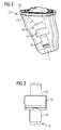
- FIG. 2 an IDO hearing instrument with antenna device is shown schematically.
- the housing 19 of the IDO hearing instrument 13 tapers on the side of the eardrum to support.
- a sound channel 17 on this side serves to deliver acoustic signals to the eardrum of the wearer.
- a hybrid circuit substrate 8 (dashed lines) inside the hearing instrument 13 and its housing 19 is arranged.
- the hybrid circuit carrier 18 comprises a signal processing device and an amplifying device which deliver control signals to the receiver 14, which is likewise arranged in the interior of the housing 19.
- the receiver 14 generates acoustic output signals that are output via the sound channel 17.
- the receiver 14 is oriented transversely to the longitudinal axis of the hearing instrument 13. Between receiver 14 and the eardrum-oriented, tapered end of the hearing instrument 13 is the antenna 16 for data transmission between the two binaural hearing instruments of the hearing instrument wearer.
- the antenna 16 is oriented in the longitudinal direction of the hearing instrument 13 and thus aligned transversely to the receiver 14.
- the transverse orientation of the receiver 14 causes a space-saving arrangement of receivers 14 and antenna 16, whose overall length is reduced by the transverse arrangement of the receiver 14.
- the transverse arrangement of the receiver 14 results in a better utilization of space in the tapered part of the housing 19. The space available in the tapered tip of the housing 19 is thus better utilized than would be the case with a longitudinally arranged receiver.
- Fig. 3 the antenna device is again shown schematically.
- the sound channel 17 is located within the antenna 16, and passes therethrough to the receiver 14.
- the receiver 14 is oriented as described above transversely to the antenna 16 and to the longitudinal direction of the IDO hearing instrument 13.
- a longitudinally arranged receiver 20 is shown by dashed lines.
- the dashed arrangement of the receiver 20 illustrates that the overall length increases with longitudinal arrangement of the receiver 20, and that at the same time results in no tapered contour of the arrangement. As explained above, it is illustrated that with longitudinal arrangement of the receiver 20, the space in the tapered tip of the hearing instrument 13 can not be exploited equally well.
- FIG. 4 An antenna receiver module is shown in perspective.
- the receiver 14 is, as explained above, oriented transversely to the antenna 16.
- the antenna 16 is disposed on a spool core 22 made of permeable material.
- the permeable coil core 22 serves as usual in the optimization of the antenna characteristic.
- the receiver 14 towards the end of the coil core 22 is formed into a shield 26.
- the shield 26 is predominantly flat and oriented transversely to the orientation of the antenna 16, ie parallel to the orientation of the receiver 14.
- the surface of the shield 26 is dimensioned so that the receiver 14 is completely or almost completely shielded by the shield 26 of the antenna or conversely, the antenna 16 is shielded from the receiver 14.
- the sound channel 17 extends through the coil core 22 and through the shield 26 to the receiver 14.
- the coil core 22 is covered on the inside by a tube 21 formed as a sound-insulating or vibration-damping material.
- the tube 21 surrounds the sound channel 17 from the antenna-side output to the receiver 14 and is there formed parallel to the plate 26 flat.
- the receiver 14 is mounted on the surface-shaped part of the tube 21 and thus also vibration isolated. Round extensions of the sound or vibration damping material are used in addition to the device integrated vibration-decoupled suspension of the device in the housing of the hearing instrument.
- the module can be pre-installed or pre-assembled in the hearing instrument.
- the pre-assembly of the antenna receiver module on the flange formed by the coil core 22 and the tube 21 reduces the assembly effort in the manufacture of the hearing instrument and thus simplifies the manufacturing process.
- a further simplification is achieved in that the coil core 22 is equipped with metallization contacts 38, which serve to contact the antenna 16. Not shown interconnects connect the metallization 38 with the terminals of the antenna 16. For this purpose, further, not shown metallization provided be, with which the winding or windings of the antenna 16 are contacted.
- Fig. 5 the field line distribution of the coil antenna with shield is shown schematically.
- the permeable coil core 22 together with the shield 26, on the one hand shields the region remote from the antenna 16 behind the shield 26.
- a receiver arranged in this region is accordingly shielded by the shield 26 from interference signals from the antenna protected.
- the field line density is increased in the axial direction on the opposite side of the shield 26 of the antenna, and thus in the transmitting and receiving direction of the antenna.
- the coil core 22 with integrally formed shield 26 accordingly effects a field characteristic optimized for the transmission and reception of data in the axial direction. This effect would be additionally increased if, which is not the case in the illustrated simulation, the spool core 22 has a through opening, for example the sound channel explained above.
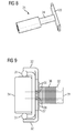
- Fig. 6 the field line profile of a receiver coil working receiver is shown schematically.
- the receiver coil 23 is arranged axially, that is, oriented in the longitudinal direction. It can be seen that the receiver coil 23 generates a strongly compressed (magnetic) field in the axial direction, while it generates a relatively weak (magnetic) field in the radial direction, that is, in the figure to the right and left.
- Fig. 7 the field line profile of the receiver is shown with shielding.
- the receiver 14 is arranged in the figure on the right of the above-described shield 26 of the permeable coil core 22.
- the coil core 22 carries the antenna 16.
- Previously explained metallization contacts 38 are integrated in the coil core 22 and serve to electrically contact the antenna 16.
- the illustrated field line course illustrates the shielding of the antenna 16 from the receiver 14 or from the signals of the receiver coil 23.
- the field lines running in the direction of the antenna 16 are deformed by the shield 26 and run through it.
- the field line density in the shield 26 is thus increased, while the field line density beyond the shield 26 is thereby simultaneously reduced.
- the strength of the (magnetic) field generated by the receiver coil 23 at the location of the coil 16 is reduced considerably.
- interference couplings of receiver signals in the antenna 16 are considerably reduced.
- Fig. 8 the above-described sound-insulating tube is shown separately.
- the tube 21 is traversed longitudinally from the sound channel.
- a flange portion 24 is provided to receive the previously explained spool core 22.
- the coil core 22 is arranged around the flange section 24, possibly also around the further longitudinal course of the tube 21 around.
- An umbrella section 25 is provided to receive the shield shaped portion of the spool core.
- the spool core section formed as a screen is placed on one side of the screen section 25, while a receiver is arranged on the opposite side of the screen section 25.
- the illustrated Tube 21 is completely made of sound-insulating material, for example in the usual way from Viton.
- FIG. 9 a further embodiment of the antenna receiver module is shown.
- the spool core 32 is formed as described above on one side as a screen 37.
- An antenna 36 is wound on the spool core 32.
- Metallization contacts 38 are used for electrical contacting of the antenna.
- the spool core 32 surrounds the receiver 34 arranged there, at least in the region shown in the figure above and below.
- the shield 37 or the coil core 32 is designed cup-shaped there, so that the receiver 34 surrounded by the coil core 32 and the shield 37 at least in a region of the shield periphery in the direction away from the antenna 36 direction.
- a particularly good shielding results when the screen 37 surrounds the receiver 34 on all sides.
- a further improvement of the shielding can be achieved in that the screen 37 encloses the receiver 34 completely and not only laterally. This results in a further improvement of the antenna, which can either be used to increase the bandwidth, or to make a shortening of the antenna while maintaining performance.
- the coil core 32 passes through a sound channel, which is the continuous tube 31 covered with sound-absorbing material.
- the tube 31 is also configured areal or cup-shaped in the area of the shield 37 and absorbs the receiver 34 in a vibration-damping manner.
- the receiver 34 is attached to the tube 31 or spool core 32.
- the illustrated receiver antenna module can be pre-assembled, so that the further assembly and manufacture of the hearing instrument is considerably simplified.
Landscapes
- Engineering & Computer Science (AREA)
- Acoustics & Sound (AREA)
- Neurosurgery (AREA)
- Otolaryngology (AREA)
- Physics & Mathematics (AREA)
- General Health & Medical Sciences (AREA)
- Health & Medical Sciences (AREA)
- Signal Processing (AREA)
- Computer Networks & Wireless Communication (AREA)
- Headphones And Earphones (AREA)
- Shielding Devices Or Components To Electric Or Magnetic Fields (AREA)
- Details Of Aerials (AREA)
- Circuit For Audible Band Transducer (AREA)
Applications Claiming Priority (1)
| Application Number | Priority Date | Filing Date | Title |
|---|---|---|---|
| DE102013210689.0A DE102013210689B3 (de) | 2013-06-07 | 2013-06-07 | Antenneneinrichtung für Hörinstrumente |
Publications (2)
| Publication Number | Publication Date |
|---|---|
| EP2811761A1 true EP2811761A1 (fr) | 2014-12-10 |
| EP2811761B1 EP2811761B1 (fr) | 2019-05-08 |
Family
ID=50189623
Family Applications (1)
| Application Number | Title | Priority Date | Filing Date |
|---|---|---|---|
| EP14157657.9A Revoked EP2811761B1 (fr) | 2013-06-07 | 2014-03-04 | Dispositif d'antenne pour appareils auditifs |
Country Status (6)
| Country | Link |
|---|---|
| US (1) | US9521494B2 (fr) |
| EP (1) | EP2811761B1 (fr) |
| CN (1) | CN104244156B (fr) |
| AU (1) | AU2014202868B2 (fr) |
| DE (1) | DE102013210689B3 (fr) |
| DK (1) | DK2811761T3 (fr) |
Cited By (2)
| Publication number | Priority date | Publication date | Assignee | Title |
|---|---|---|---|---|
| EP3451703A1 (fr) * | 2017-09-01 | 2019-03-06 | Sivantos Pte. Ltd. | Appareil de correction auditive |
| DE102019217861B3 (de) * | 2019-11-20 | 2021-05-20 | Sivantos Pte. Ltd. | Hörgerät |
Families Citing this family (19)
| Publication number | Priority date | Publication date | Assignee | Title |
|---|---|---|---|---|
| DE102014200524A1 (de) | 2014-01-14 | 2015-07-16 | Siemens Medical Instruments Pte. Ltd. | Antenneneinrichtung für Hörinstrumente |
| EP3269155B1 (fr) * | 2015-03-13 | 2019-01-02 | Sivantos Pte. Ltd. | Système d'aide auditive binaurale |
| US10321248B2 (en) * | 2015-06-03 | 2019-06-11 | Gn Hearing A/S | Hearing device shell with guide structure |
| US9661426B2 (en) * | 2015-06-22 | 2017-05-23 | Gn Hearing A/S | Hearing aid having combined antennas |
| EP3110175B1 (fr) * | 2015-06-24 | 2020-03-25 | Oticon A/s | Dispositif auditif comprenant une unité d'antenne encastrée dans tiroir de batterie |
| DE102016202658A1 (de) * | 2016-02-22 | 2017-08-24 | Sivantos Pte. Ltd. | Lautsprechermodul für ein Hörgerät und Hörgerät |
| CN108701901B (zh) * | 2016-03-07 | 2020-12-01 | 西万拓私人有限公司 | 天线 |
| US10764695B2 (en) * | 2016-12-20 | 2020-09-01 | Sonova Ag | BTE hearing instrument comprising an open-end transmission line antenna |
| DK3343954T3 (da) * | 2016-12-29 | 2023-07-03 | Oticon As | Høreanordning indbefattende en udvendig antennedel og en indvendig antennedel |
| DE102017210447A1 (de) | 2017-06-21 | 2018-12-27 | Sivantos Pte. Ltd. | Hörgerät |
| US10511920B2 (en) | 2018-04-13 | 2019-12-17 | Starkey Laboratories, Inc. | Ear-worn electronic device incorporating directional magnetic antenna |
| DE102018209189A1 (de) * | 2018-06-08 | 2019-12-12 | Sivantos Pte. Ltd. | Antenne sowie Gerät mit einer solchen Antenne |
| EP3831095A4 (fr) | 2018-07-31 | 2022-06-08 | Earlens Corporation | Couplage inductif en champ proche dans un système auditif à contact |
| US12580300B2 (en) * | 2019-07-03 | 2026-03-17 | Starkey Laboratories, Inc. | Circular polarized spiral antenna for hearing assistance devices |
| EP3806493B1 (fr) * | 2019-10-11 | 2023-07-19 | GN Hearing A/S | Dispositif auditif doté d'une bobine d'induction magnétique |
| DE102020201480A1 (de) * | 2020-02-06 | 2021-08-12 | Sivantos Pte. Ltd. | Hörgerät |
| US12149891B2 (en) * | 2021-05-21 | 2024-11-19 | Gn Hearing A/S | Hearing aid with dual coil components for noise cancellation |
| US20240293277A1 (en) * | 2021-09-17 | 2024-09-05 | Stryker Corporation | System for locating patient support apparatuses |
| DE102023202591B4 (de) * | 2023-03-22 | 2025-01-09 | Sivantos Pte. Ltd. | Lautsprechersystem für eine im Ohr zu tragende Hörvorrichtung |
Citations (2)
| Publication number | Priority date | Publication date | Assignee | Title |
|---|---|---|---|---|
| US20050168396A1 (en) * | 2004-01-30 | 2005-08-04 | Victorian Thomas A. | Method and apparatus for a wireless hearing aid antenna |
| US20090274328A1 (en) * | 2008-05-05 | 2009-11-05 | Volker Gebhardt | Apparatus and method for reducing interference effects in the case of a wireless data transmission in hearing device applications |
Family Cites Families (17)
| Publication number | Priority date | Publication date | Assignee | Title |
|---|---|---|---|---|
| US5640457A (en) | 1995-11-13 | 1997-06-17 | Gnecco; Louis Thomas | Electromagnetically shielded hearing aid |
| JP3896965B2 (ja) | 2002-01-17 | 2007-03-22 | 三菱マテリアル株式会社 | リーダ/ライタ用アンテナ及び該アンテナを備えたリーダ/ライタ |
| DE10236940B3 (de) | 2002-08-12 | 2004-02-19 | Siemens Audiologische Technik Gmbh | Platzsparende Antennenanordnung für Hörhilfegeräte |
| EP1719384B1 (fr) * | 2004-02-19 | 2011-05-04 | Oticon A/S | Appareil auditif equipé d'une antenne destinée à l'emission et à la reception de signaux électromagnétiques et batterie blindante |
| DE102004017832B3 (de) | 2004-04-13 | 2005-10-20 | Siemens Audiologische Technik | Hörgerät |
| US7460681B2 (en) | 2004-07-20 | 2008-12-02 | Sonion Nederland B.V. | Radio frequency shielding for receivers within hearing aids and listening devices |
| DK1788592T3 (da) * | 2005-11-17 | 2012-04-16 | Oticon As | Afskærmet spole til induktive trådløse anvendelser |
| JP5612238B2 (ja) | 2006-02-20 | 2014-10-22 | 株式会社スマート | 軸対称垂直磁界センサシステム |
| DE102006043909B3 (de) * | 2006-09-19 | 2008-04-17 | Siemens Audiologische Technik Gmbh | Hörer mit zusätzlicher Abschirmeinrichtung und Hörgerät mit diesem Hörer |
| DE102007007800B3 (de) | 2007-02-16 | 2008-08-28 | Siemens Audiologische Technik Gmbh | Hörvorrichtung mit Hörerkompensationsspule |
| DK2351382T3 (da) | 2008-09-26 | 2013-08-19 | Oticon As | Høreapparat med udskiftelige hylsterdele og trådløs kommunikation |
| DE102009007233B4 (de) * | 2009-02-03 | 2012-07-26 | Siemens Medical Instruments Pte. Ltd. | Hörvorrichtung mit Störkompensation und Entwurfsverfahren |
| EP2278828B1 (fr) | 2009-07-23 | 2017-09-06 | Starkey Laboratories, Inc. | Procédé et appareil pour blindage électromagnétique isolé pour une utilisation dans des dispositifs d'assistance auditive |
| DE112012003755T5 (de) | 2011-09-09 | 2014-09-18 | Knowles Electronics, Llc | HF-Abschirmung für akustische Einrichtungen |
| US20130188803A1 (en) * | 2012-01-20 | 2013-07-25 | Qualcomm Incorporated | Earpiece |
| EP3151585B1 (fr) * | 2012-03-16 | 2018-08-22 | Sonova AG | Module d'antenne pour un dispositif auditif, embout et dispositif auditif doté d'un tel module d'antenne |
| US9237404B2 (en) * | 2012-12-28 | 2016-01-12 | Gn Resound A/S | Dipole antenna for a hearing aid |
-
2013
- 2013-06-07 DE DE102013210689.0A patent/DE102013210689B3/de active Active
-
2014
- 2014-03-04 EP EP14157657.9A patent/EP2811761B1/fr not_active Revoked
- 2014-03-04 DK DK14157657.9T patent/DK2811761T3/da active
- 2014-05-27 AU AU2014202868A patent/AU2014202868B2/en not_active Ceased
- 2014-06-06 CN CN201410250412.0A patent/CN104244156B/zh active Active
- 2014-06-09 US US14/299,144 patent/US9521494B2/en active Active
Patent Citations (2)
| Publication number | Priority date | Publication date | Assignee | Title |
|---|---|---|---|---|
| US20050168396A1 (en) * | 2004-01-30 | 2005-08-04 | Victorian Thomas A. | Method and apparatus for a wireless hearing aid antenna |
| US20090274328A1 (en) * | 2008-05-05 | 2009-11-05 | Volker Gebhardt | Apparatus and method for reducing interference effects in the case of a wireless data transmission in hearing device applications |
Cited By (8)
| Publication number | Priority date | Publication date | Assignee | Title |
|---|---|---|---|---|
| EP3451703A1 (fr) * | 2017-09-01 | 2019-03-06 | Sivantos Pte. Ltd. | Appareil de correction auditive |
| DE102017215372A1 (de) | 2017-09-01 | 2019-03-07 | Sivantos Pte. Ltd. | Hörgerät |
| DE102019217861B3 (de) * | 2019-11-20 | 2021-05-20 | Sivantos Pte. Ltd. | Hörgerät |
| CN112825565A (zh) * | 2019-11-20 | 2021-05-21 | 西万拓私人有限公司 | 听力装置 |
| EP3826327A1 (fr) | 2019-11-20 | 2021-05-26 | Sivantos Pte. Ltd. | Appareil auditif |
| US11343627B2 (en) | 2019-11-20 | 2022-05-24 | Sivantos Pte. Ltd. | Hearing device |
| US11627423B2 (en) | 2019-11-20 | 2023-04-11 | Sivantos Pte. Ltd. | Hearing device |
| US12143778B2 (en) | 2019-11-20 | 2024-11-12 | Sivantos Pte. Ltd. | Method for producing a hearing aid with an antenna module, and hearing aid |
Also Published As
| Publication number | Publication date |
|---|---|
| DK2811761T3 (da) | 2019-08-12 |
| CN104244156A (zh) | 2014-12-24 |
| DE102013210689B3 (de) | 2014-10-02 |
| CN104244156B (zh) | 2017-10-13 |
| EP2811761B1 (fr) | 2019-05-08 |
| AU2014202868A1 (en) | 2015-01-15 |
| US9521494B2 (en) | 2016-12-13 |
| US20140363037A1 (en) | 2014-12-11 |
| AU2014202868B2 (en) | 2015-12-10 |
Similar Documents
| Publication | Publication Date | Title |
|---|---|---|
| EP2811761B1 (fr) | Dispositif d'antenne pour appareils auditifs | |
| EP2894880B1 (fr) | Dispositif d'antenne pour appareils auditifs | |
| EP2782363B1 (fr) | Appareillage auditif binaural et écouteur | |
| US10231063B2 (en) | Binaural hearing aid system | |
| US10021495B2 (en) | Antenna for hearing device, ear tip and hearing device provided with such an antenna | |
| EP3413587B1 (fr) | Appareil auditif, en particulier appareil de correction auditive derrière l'oreille | |
| DE102018207179B4 (de) | Hörhilfegerät mit Elektronikrahmen und darin integrierter Antenne | |
| US11924615B2 (en) | Hearing aid, antenna for a hearing aid, and method for producing a hearing aid | |
| EP3209032B1 (fr) | Module de haut-parleur pour un appareil auditif et appareil auditif | |
| EP2375784B1 (fr) | Appareil auditif doté d'un blindage de haut-parleur amorphe | |
| DE102017012195B4 (de) | Hörgerät, insbesondere Hinter-dem-Ohr-Hörhilfegerät | |
| EP3739906B1 (fr) | Instrument auditif | |
| DE102006049469B4 (de) | Hörgerät mit stromführendem Metallbügel | |
| DE102010012946B4 (de) | Hörgerät mit amorpher Lautsprecherabschirmung | |
| DE102017220187A1 (de) | Hörhilfegerät | |
| DE102009008618A1 (de) | Hörvorrichtung mit zwei elektrischen Einheiten, die über Drähte mit einander verbunden sind. |
Legal Events
| Date | Code | Title | Description |
|---|---|---|---|
| PUAI | Public reference made under article 153(3) epc to a published international application that has entered the european phase |
Free format text: ORIGINAL CODE: 0009012 |
|
| 17P | Request for examination filed |
Effective date: 20140304 |
|
| AK | Designated contracting states |
Kind code of ref document: A1 Designated state(s): AL AT BE BG CH CY CZ DE DK EE ES FI FR GB GR HR HU IE IS IT LI LT LU LV MC MK MT NL NO PL PT RO RS SE SI SK SM TR |
|
| AX | Request for extension of the european patent |
Extension state: BA ME |
|
| R17P | Request for examination filed (corrected) |
Effective date: 20150610 |
|
| RBV | Designated contracting states (corrected) |
Designated state(s): AL AT BE BG CH CY CZ DE DK EE ES FI FR GB GR HR HU IE IS IT LI LT LU LV MC MK MT NL NO PL PT RO RS SE SI SK SM TR |
|
| RAP1 | Party data changed (applicant data changed or rights of an application transferred) |
Owner name: SIVANTOS PTE. LTD. |
|
| STAA | Information on the status of an ep patent application or granted ep patent |
Free format text: STATUS: EXAMINATION IS IN PROGRESS |
|
| RAP1 | Party data changed (applicant data changed or rights of an application transferred) |
Owner name: SIVANTOS PTE. LTD. |
|
| 17Q | First examination report despatched |
Effective date: 20180219 |
|
| RIC1 | Information provided on ipc code assigned before grant |
Ipc: H01Q 7/00 20060101ALI20180928BHEP Ipc: H01Q 1/27 20060101ALI20180928BHEP Ipc: H04R 25/00 20060101AFI20180928BHEP |
|
| GRAP | Despatch of communication of intention to grant a patent |
Free format text: ORIGINAL CODE: EPIDOSNIGR1 |
|
| STAA | Information on the status of an ep patent application or granted ep patent |
Free format text: STATUS: GRANT OF PATENT IS INTENDED |
|
| RIC1 | Information provided on ipc code assigned before grant |
Ipc: H01Q 1/22 20060101ALI20181018BHEP Ipc: H01Q 1/27 20060101ALI20181018BHEP Ipc: H01Q 7/00 20060101ALI20181018BHEP Ipc: H04R 25/00 20060101AFI20181018BHEP |
|
| INTG | Intention to grant announced |
Effective date: 20181120 |
|
| GRAS | Grant fee paid |
Free format text: ORIGINAL CODE: EPIDOSNIGR3 |
|
| GRAA | (expected) grant |
Free format text: ORIGINAL CODE: 0009210 |
|
| STAA | Information on the status of an ep patent application or granted ep patent |
Free format text: STATUS: THE PATENT HAS BEEN GRANTED |
|
| AK | Designated contracting states |
Kind code of ref document: B1 Designated state(s): AL AT BE BG CH CY CZ DE DK EE ES FI FR GB GR HR HU IE IS IT LI LT LU LV MC MK MT NL NO PL PT RO RS SE SI SK SM TR |
|
| REG | Reference to a national code |
Ref country code: GB Ref legal event code: FG4D Free format text: NOT ENGLISH |
|
| REG | Reference to a national code |
Ref country code: CH Ref legal event code: EP Ref country code: AT Ref legal event code: REF Ref document number: 1132100 Country of ref document: AT Kind code of ref document: T Effective date: 20190515 |
|
| REG | Reference to a national code |
Ref country code: DE Ref legal event code: R096 Ref document number: 502014011632 Country of ref document: DE |
|
| REG | Reference to a national code |
Ref country code: IE Ref legal event code: FG4D Free format text: LANGUAGE OF EP DOCUMENT: GERMAN |
|
| REG | Reference to a national code |
Ref country code: CH Ref legal event code: NV Representative=s name: E. BLUM AND CO. AG PATENT- UND MARKENANWAELTE , CH |
|
| REG | Reference to a national code |
Ref country code: DK Ref legal event code: T3 Effective date: 20190807 |
|
| REG | Reference to a national code |
Ref country code: NL Ref legal event code: MP Effective date: 20190508 |
|
| REG | Reference to a national code |
Ref country code: LT Ref legal event code: MG4D |
|
| PG25 | Lapsed in a contracting state [announced via postgrant information from national office to epo] |
Ref country code: FI Free format text: LAPSE BECAUSE OF FAILURE TO SUBMIT A TRANSLATION OF THE DESCRIPTION OR TO PAY THE FEE WITHIN THE PRESCRIBED TIME-LIMIT Effective date: 20190508 Ref country code: NO Free format text: LAPSE BECAUSE OF FAILURE TO SUBMIT A TRANSLATION OF THE DESCRIPTION OR TO PAY THE FEE WITHIN THE PRESCRIBED TIME-LIMIT Effective date: 20190808 Ref country code: SE Free format text: LAPSE BECAUSE OF FAILURE TO SUBMIT A TRANSLATION OF THE DESCRIPTION OR TO PAY THE FEE WITHIN THE PRESCRIBED TIME-LIMIT Effective date: 20190508 Ref country code: ES Free format text: LAPSE BECAUSE OF FAILURE TO SUBMIT A TRANSLATION OF THE DESCRIPTION OR TO PAY THE FEE WITHIN THE PRESCRIBED TIME-LIMIT Effective date: 20190508 Ref country code: PT Free format text: LAPSE BECAUSE OF FAILURE TO SUBMIT A TRANSLATION OF THE DESCRIPTION OR TO PAY THE FEE WITHIN THE PRESCRIBED TIME-LIMIT Effective date: 20190908 Ref country code: NL Free format text: LAPSE BECAUSE OF FAILURE TO SUBMIT A TRANSLATION OF THE DESCRIPTION OR TO PAY THE FEE WITHIN THE PRESCRIBED TIME-LIMIT Effective date: 20190508 Ref country code: AL Free format text: LAPSE BECAUSE OF FAILURE TO SUBMIT A TRANSLATION OF THE DESCRIPTION OR TO PAY THE FEE WITHIN THE PRESCRIBED TIME-LIMIT Effective date: 20190508 Ref country code: LT Free format text: LAPSE BECAUSE OF FAILURE TO SUBMIT A TRANSLATION OF THE DESCRIPTION OR TO PAY THE FEE WITHIN THE PRESCRIBED TIME-LIMIT Effective date: 20190508 Ref country code: HR Free format text: LAPSE BECAUSE OF FAILURE TO SUBMIT A TRANSLATION OF THE DESCRIPTION OR TO PAY THE FEE WITHIN THE PRESCRIBED TIME-LIMIT Effective date: 20190508 |
|
| PG25 | Lapsed in a contracting state [announced via postgrant information from national office to epo] |
Ref country code: BG Free format text: LAPSE BECAUSE OF FAILURE TO SUBMIT A TRANSLATION OF THE DESCRIPTION OR TO PAY THE FEE WITHIN THE PRESCRIBED TIME-LIMIT Effective date: 20190808 Ref country code: GR Free format text: LAPSE BECAUSE OF FAILURE TO SUBMIT A TRANSLATION OF THE DESCRIPTION OR TO PAY THE FEE WITHIN THE PRESCRIBED TIME-LIMIT Effective date: 20190809 Ref country code: RS Free format text: LAPSE BECAUSE OF FAILURE TO SUBMIT A TRANSLATION OF THE DESCRIPTION OR TO PAY THE FEE WITHIN THE PRESCRIBED TIME-LIMIT Effective date: 20190508 Ref country code: LV Free format text: LAPSE BECAUSE OF FAILURE TO SUBMIT A TRANSLATION OF THE DESCRIPTION OR TO PAY THE FEE WITHIN THE PRESCRIBED TIME-LIMIT Effective date: 20190508 |
|
| PG25 | Lapsed in a contracting state [announced via postgrant information from national office to epo] |
Ref country code: CZ Free format text: LAPSE BECAUSE OF FAILURE TO SUBMIT A TRANSLATION OF THE DESCRIPTION OR TO PAY THE FEE WITHIN THE PRESCRIBED TIME-LIMIT Effective date: 20190508 Ref country code: RO Free format text: LAPSE BECAUSE OF FAILURE TO SUBMIT A TRANSLATION OF THE DESCRIPTION OR TO PAY THE FEE WITHIN THE PRESCRIBED TIME-LIMIT Effective date: 20190508 Ref country code: EE Free format text: LAPSE BECAUSE OF FAILURE TO SUBMIT A TRANSLATION OF THE DESCRIPTION OR TO PAY THE FEE WITHIN THE PRESCRIBED TIME-LIMIT Effective date: 20190508 Ref country code: SK Free format text: LAPSE BECAUSE OF FAILURE TO SUBMIT A TRANSLATION OF THE DESCRIPTION OR TO PAY THE FEE WITHIN THE PRESCRIBED TIME-LIMIT Effective date: 20190508 |
|
| REG | Reference to a national code |
Ref country code: DE Ref legal event code: R026 Ref document number: 502014011632 Country of ref document: DE |
|
| PLBI | Opposition filed |
Free format text: ORIGINAL CODE: 0009260 |
|
| PLAX | Notice of opposition and request to file observation + time limit sent |
Free format text: ORIGINAL CODE: EPIDOSNOBS2 |
|
| PG25 | Lapsed in a contracting state [announced via postgrant information from national office to epo] |
Ref country code: IT Free format text: LAPSE BECAUSE OF FAILURE TO SUBMIT A TRANSLATION OF THE DESCRIPTION OR TO PAY THE FEE WITHIN THE PRESCRIBED TIME-LIMIT Effective date: 20190508 Ref country code: SM Free format text: LAPSE BECAUSE OF FAILURE TO SUBMIT A TRANSLATION OF THE DESCRIPTION OR TO PAY THE FEE WITHIN THE PRESCRIBED TIME-LIMIT Effective date: 20190508 |
|
| PLAB | Opposition data, opponent's data or that of the opponent's representative modified |
Free format text: ORIGINAL CODE: 0009299OPPO |
|
| 26 | Opposition filed |
Opponent name: GN HEARING A/S / OTICON A/S Effective date: 20200210 |
|
| PG25 | Lapsed in a contracting state [announced via postgrant information from national office to epo] |
Ref country code: TR Free format text: LAPSE BECAUSE OF FAILURE TO SUBMIT A TRANSLATION OF THE DESCRIPTION OR TO PAY THE FEE WITHIN THE PRESCRIBED TIME-LIMIT Effective date: 20190508 |
|
| R26 | Opposition filed (corrected) |
Opponent name: GN HEARING A/S Effective date: 20200210 |
|
| PG25 | Lapsed in a contracting state [announced via postgrant information from national office to epo] |
Ref country code: PL Free format text: LAPSE BECAUSE OF FAILURE TO SUBMIT A TRANSLATION OF THE DESCRIPTION OR TO PAY THE FEE WITHIN THE PRESCRIBED TIME-LIMIT Effective date: 20190508 |
|
| PG25 | Lapsed in a contracting state [announced via postgrant information from national office to epo] |
Ref country code: SI Free format text: LAPSE BECAUSE OF FAILURE TO SUBMIT A TRANSLATION OF THE DESCRIPTION OR TO PAY THE FEE WITHIN THE PRESCRIBED TIME-LIMIT Effective date: 20190508 |
|
| PLBB | Reply of patent proprietor to notice(s) of opposition received |
Free format text: ORIGINAL CODE: EPIDOSNOBS3 |
|
| PG25 | Lapsed in a contracting state [announced via postgrant information from national office to epo] |
Ref country code: MC Free format text: LAPSE BECAUSE OF FAILURE TO SUBMIT A TRANSLATION OF THE DESCRIPTION OR TO PAY THE FEE WITHIN THE PRESCRIBED TIME-LIMIT Effective date: 20190508 |
|
| REG | Reference to a national code |
Ref country code: BE Ref legal event code: MM Effective date: 20200331 |
|
| PG25 | Lapsed in a contracting state [announced via postgrant information from national office to epo] |
Ref country code: LU Free format text: LAPSE BECAUSE OF NON-PAYMENT OF DUE FEES Effective date: 20200304 |
|
| PG25 | Lapsed in a contracting state [announced via postgrant information from national office to epo] |
Ref country code: IE Free format text: LAPSE BECAUSE OF NON-PAYMENT OF DUE FEES Effective date: 20200304 |
|
| PG25 | Lapsed in a contracting state [announced via postgrant information from national office to epo] |
Ref country code: BE Free format text: LAPSE BECAUSE OF NON-PAYMENT OF DUE FEES Effective date: 20200331 |
|
| PLCK | Communication despatched that opposition was rejected |
Free format text: ORIGINAL CODE: EPIDOSNREJ1 |
|
| REG | Reference to a national code |
Ref country code: AT Ref legal event code: MM01 Ref document number: 1132100 Country of ref document: AT Kind code of ref document: T Effective date: 20200304 |
|
| APBM | Appeal reference recorded |
Free format text: ORIGINAL CODE: EPIDOSNREFNO |
|
| APBP | Date of receipt of notice of appeal recorded |
Free format text: ORIGINAL CODE: EPIDOSNNOA2O |
|
| APAH | Appeal reference modified |
Free format text: ORIGINAL CODE: EPIDOSCREFNO |
|
| APBQ | Date of receipt of statement of grounds of appeal recorded |
Free format text: ORIGINAL CODE: EPIDOSNNOA3O |
|
| PG25 | Lapsed in a contracting state [announced via postgrant information from national office to epo] |
Ref country code: AT Free format text: LAPSE BECAUSE OF NON-PAYMENT OF DUE FEES Effective date: 20200304 |
|
| PG25 | Lapsed in a contracting state [announced via postgrant information from national office to epo] |
Ref country code: MT Free format text: LAPSE BECAUSE OF FAILURE TO SUBMIT A TRANSLATION OF THE DESCRIPTION OR TO PAY THE FEE WITHIN THE PRESCRIBED TIME-LIMIT Effective date: 20190508 Ref country code: CY Free format text: LAPSE BECAUSE OF FAILURE TO SUBMIT A TRANSLATION OF THE DESCRIPTION OR TO PAY THE FEE WITHIN THE PRESCRIBED TIME-LIMIT Effective date: 20190508 |
|
| PG25 | Lapsed in a contracting state [announced via postgrant information from national office to epo] |
Ref country code: MK Free format text: LAPSE BECAUSE OF FAILURE TO SUBMIT A TRANSLATION OF THE DESCRIPTION OR TO PAY THE FEE WITHIN THE PRESCRIBED TIME-LIMIT Effective date: 20190508 Ref country code: IS Free format text: LAPSE BECAUSE OF FAILURE TO SUBMIT A TRANSLATION OF THE DESCRIPTION OR TO PAY THE FEE WITHIN THE PRESCRIBED TIME-LIMIT Effective date: 20190908 |
|
| PGFP | Annual fee paid to national office [announced via postgrant information from national office to epo] |
Ref country code: FR Payment date: 20230320 Year of fee payment: 10 Ref country code: DK Payment date: 20230323 Year of fee payment: 10 |
|
| PGFP | Annual fee paid to national office [announced via postgrant information from national office to epo] |
Ref country code: GB Payment date: 20230323 Year of fee payment: 10 Ref country code: DE Payment date: 20230320 Year of fee payment: 10 |
|
| PGFP | Annual fee paid to national office [announced via postgrant information from national office to epo] |
Ref country code: CH Payment date: 20230402 Year of fee payment: 10 |
|
| REG | Reference to a national code |
Ref country code: DE Ref legal event code: R103 Ref document number: 502014011632 Country of ref document: DE Ref country code: DE Ref legal event code: R064 Ref document number: 502014011632 Country of ref document: DE |
|
| APBU | Appeal procedure closed |
Free format text: ORIGINAL CODE: EPIDOSNNOA9O |
|
| RDAD | Information modified related to despatch of communication that patent is revoked |
Free format text: ORIGINAL CODE: EPIDOSCREV1 |
|
| RDAF | Communication despatched that patent is revoked |
Free format text: ORIGINAL CODE: EPIDOSNREV1 |
|
| RDAG | Patent revoked |
Free format text: ORIGINAL CODE: 0009271 |
|
| STAA | Information on the status of an ep patent application or granted ep patent |
Free format text: STATUS: PATENT REVOKED |
|
| REG | Reference to a national code |
Ref country code: CH Ref legal event code: PL |
|
| 27W | Patent revoked |
Effective date: 20230921 |
|
| GBPR | Gb: patent revoked under art. 102 of the ep convention designating the uk as contracting state |
Effective date: 20230921 |
|
| REG | Reference to a national code |
Ref country code: AT Ref legal event code: MA03 Ref document number: 1132100 Country of ref document: AT Kind code of ref document: T Effective date: 20230921 |