EP2814018A1 - Dispositif d'avertissement - Google Patents
Dispositif d'avertissement Download PDFInfo
- Publication number
- EP2814018A1 EP2814018A1 EP12868170.7A EP12868170A EP2814018A1 EP 2814018 A1 EP2814018 A1 EP 2814018A1 EP 12868170 A EP12868170 A EP 12868170A EP 2814018 A1 EP2814018 A1 EP 2814018A1
- Authority
- EP
- European Patent Office
- Prior art keywords
- vehicle
- warning
- time
- section
- host vehicle
- Prior art date
- Legal status (The legal status is an assumption and is not a legal conclusion. Google has not performed a legal analysis and makes no representation as to the accuracy of the status listed.)
- Withdrawn
Links
- 238000001514 detection method Methods 0.000 claims abstract description 72
- 238000013459 approach Methods 0.000 claims abstract description 39
- 230000000052 comparative effect Effects 0.000 description 18
- 230000004397 blinking Effects 0.000 description 9
- 238000000034 method Methods 0.000 description 8
- 230000035559 beat frequency Effects 0.000 description 3
- 230000005540 biological transmission Effects 0.000 description 3
- 238000002474 experimental method Methods 0.000 description 3
- 238000010586 diagram Methods 0.000 description 2
- 230000000694 effects Effects 0.000 description 2
- 230000006870 function Effects 0.000 description 2
- 238000009434 installation Methods 0.000 description 2
- 230000015654 memory Effects 0.000 description 2
- 238000001228 spectrum Methods 0.000 description 2
- 230000003111 delayed effect Effects 0.000 description 1
- 239000012466 permeate Substances 0.000 description 1
- 239000011347 resin Substances 0.000 description 1
- 229920005989 resin Polymers 0.000 description 1
Images


Classifications
-
- B—PERFORMING OPERATIONS; TRANSPORTING
- B60—VEHICLES IN GENERAL
- B60Q—ARRANGEMENT OF SIGNALLING OR LIGHTING DEVICES, THE MOUNTING OR SUPPORTING THEREOF OR CIRCUITS THEREFOR, FOR VEHICLES IN GENERAL
- B60Q9/00—Arrangement or adaptation of signal devices not provided for in one of main groups B60Q1/00 - B60Q7/00, e.g. haptic signalling
- B60Q9/008—Arrangement or adaptation of signal devices not provided for in one of main groups B60Q1/00 - B60Q7/00, e.g. haptic signalling for anti-collision purposes
-
- G—PHYSICS
- G01—MEASURING; TESTING
- G01S—RADIO DIRECTION-FINDING; RADIO NAVIGATION; DETERMINING DISTANCE OR VELOCITY BY USE OF RADIO WAVES; LOCATING OR PRESENCE-DETECTING BY USE OF THE REFLECTION OR RERADIATION OF RADIO WAVES; ANALOGOUS ARRANGEMENTS USING OTHER WAVES
- G01S13/00—Systems using the reflection or reradiation of radio waves, e.g. radar systems; Analogous systems using reflection or reradiation of waves whose nature or wavelength is irrelevant or unspecified
- G01S13/02—Systems using reflection of radio waves, e.g. primary radar systems; Analogous systems
- G01S13/06—Systems determining position data of a target
- G01S13/42—Simultaneous measurement of distance and other co-ordinates
-
- G—PHYSICS
- G01—MEASURING; TESTING
- G01S—RADIO DIRECTION-FINDING; RADIO NAVIGATION; DETERMINING DISTANCE OR VELOCITY BY USE OF RADIO WAVES; LOCATING OR PRESENCE-DETECTING BY USE OF THE REFLECTION OR RERADIATION OF RADIO WAVES; ANALOGOUS ARRANGEMENTS USING OTHER WAVES
- G01S13/00—Systems using the reflection or reradiation of radio waves, e.g. radar systems; Analogous systems using reflection or reradiation of waves whose nature or wavelength is irrelevant or unspecified
- G01S13/87—Combinations of radar systems, e.g. primary radar and secondary radar
-
- G—PHYSICS
- G01—MEASURING; TESTING
- G01S—RADIO DIRECTION-FINDING; RADIO NAVIGATION; DETERMINING DISTANCE OR VELOCITY BY USE OF RADIO WAVES; LOCATING OR PRESENCE-DETECTING BY USE OF THE REFLECTION OR RERADIATION OF RADIO WAVES; ANALOGOUS ARRANGEMENTS USING OTHER WAVES
- G01S13/00—Systems using the reflection or reradiation of radio waves, e.g. radar systems; Analogous systems using reflection or reradiation of waves whose nature or wavelength is irrelevant or unspecified
- G01S13/88—Radar or analogous systems specially adapted for specific applications
- G01S13/93—Radar or analogous systems specially adapted for specific applications for anti-collision purposes
- G01S13/931—Radar or analogous systems specially adapted for specific applications for anti-collision purposes of land vehicles
-
- G—PHYSICS
- G08—SIGNALLING
- G08G—TRAFFIC CONTROL SYSTEMS
- G08G1/00—Traffic control systems for road vehicles
- G08G1/16—Anti-collision systems
- G08G1/166—Anti-collision systems for active traffic, e.g. moving vehicles, pedestrians, bikes
-
- G—PHYSICS
- G08—SIGNALLING
- G08G—TRAFFIC CONTROL SYSTEMS
- G08G1/00—Traffic control systems for road vehicles
- G08G1/16—Anti-collision systems
- G08G1/168—Driving aids for parking, e.g. acoustic or visual feedback on parking space
-
- G—PHYSICS
- G01—MEASURING; TESTING
- G01S—RADIO DIRECTION-FINDING; RADIO NAVIGATION; DETERMINING DISTANCE OR VELOCITY BY USE OF RADIO WAVES; LOCATING OR PRESENCE-DETECTING BY USE OF THE REFLECTION OR RERADIATION OF RADIO WAVES; ANALOGOUS ARRANGEMENTS USING OTHER WAVES
- G01S13/00—Systems using the reflection or reradiation of radio waves, e.g. radar systems; Analogous systems using reflection or reradiation of waves whose nature or wavelength is irrelevant or unspecified
- G01S13/88—Radar or analogous systems specially adapted for specific applications
- G01S13/93—Radar or analogous systems specially adapted for specific applications for anti-collision purposes
- G01S13/931—Radar or analogous systems specially adapted for specific applications for anti-collision purposes of land vehicles
- G01S2013/9315—Monitoring blind spots
-
- G—PHYSICS
- G01—MEASURING; TESTING
- G01S—RADIO DIRECTION-FINDING; RADIO NAVIGATION; DETERMINING DISTANCE OR VELOCITY BY USE OF RADIO WAVES; LOCATING OR PRESENCE-DETECTING BY USE OF THE REFLECTION OR RERADIATION OF RADIO WAVES; ANALOGOUS ARRANGEMENTS USING OTHER WAVES
- G01S13/00—Systems using the reflection or reradiation of radio waves, e.g. radar systems; Analogous systems using reflection or reradiation of waves whose nature or wavelength is irrelevant or unspecified
- G01S13/88—Radar or analogous systems specially adapted for specific applications
- G01S13/93—Radar or analogous systems specially adapted for specific applications for anti-collision purposes
- G01S13/931—Radar or analogous systems specially adapted for specific applications for anti-collision purposes of land vehicles
- G01S2013/9317—Driving backwards
-
- G—PHYSICS
- G01—MEASURING; TESTING
- G01S—RADIO DIRECTION-FINDING; RADIO NAVIGATION; DETERMINING DISTANCE OR VELOCITY BY USE OF RADIO WAVES; LOCATING OR PRESENCE-DETECTING BY USE OF THE REFLECTION OR RERADIATION OF RADIO WAVES; ANALOGOUS ARRANGEMENTS USING OTHER WAVES
- G01S13/00—Systems using the reflection or reradiation of radio waves, e.g. radar systems; Analogous systems using reflection or reradiation of waves whose nature or wavelength is irrelevant or unspecified
- G01S13/88—Radar or analogous systems specially adapted for specific applications
- G01S13/93—Radar or analogous systems specially adapted for specific applications for anti-collision purposes
- G01S13/931—Radar or analogous systems specially adapted for specific applications for anti-collision purposes of land vehicles
- G01S2013/9327—Sensor installation details
- G01S2013/93272—Sensor installation details in the back of the vehicles
-
- G—PHYSICS
- G01—MEASURING; TESTING
- G01S—RADIO DIRECTION-FINDING; RADIO NAVIGATION; DETERMINING DISTANCE OR VELOCITY BY USE OF RADIO WAVES; LOCATING OR PRESENCE-DETECTING BY USE OF THE REFLECTION OR RERADIATION OF RADIO WAVES; ANALOGOUS ARRANGEMENTS USING OTHER WAVES
- G01S13/00—Systems using the reflection or reradiation of radio waves, e.g. radar systems; Analogous systems using reflection or reradiation of waves whose nature or wavelength is irrelevant or unspecified
- G01S13/88—Radar or analogous systems specially adapted for specific applications
- G01S13/93—Radar or analogous systems specially adapted for specific applications for anti-collision purposes
- G01S13/931—Radar or analogous systems specially adapted for specific applications for anti-collision purposes of land vehicles
- G01S2013/9327—Sensor installation details
- G01S2013/93274—Sensor installation details on the side of the vehicles
Definitions
- the present invention relates to a warning device.
- a vehicle radar system that includes a beam forming circuit and a beam combining circuit has been available.
- the beam forming circuit provides a plurality of antenna beams to a plurality of beam ports.
- the beam combining circuit receives the plurality of antenna beams from the beam forming circuit and combines these antenna beams to create the desired number of antenna beams.
- each of first and second beams at both ends has a narrower width than that of an intermediate beam (see Patent Document 1, for example).
- Patent Document 1 Japanese Patent Application Publication No. 2006-191610 ( JP 2006-191610 A )
- the second vehicle detected as the ghost is detected as a vehicle that satisfies a condition such as a same speed as the first other vehicle, a specified time difference by the multipath, an arrival direction that is substantially and linearly symmetrical to a center axis of the host vehicle, or the like.
- a purpose is to provide a warning device, usability of which is improved.
- a warning device of an embodiment of the present invention includes: a first detection section for detecting another vehicle approaching from right rear of a host vehicle; a second detection section for detecting another vehicle approaching from left rear of the host vehicle; a warning section for issuing a warning to inform a driver of the host vehicle of approach of another vehicle; and a control section for ordering the warning section to issue the warning when the first detection section or the second detection section detects another vehicle.
- the control section extends issuance of the warning of a first other vehicle for a specified time in a case where one of the first detection section and the second detection section detects the first other vehicle and another of the first detection section and the second detection section thereafter detects a second other vehicle when the host vehicle is reversed from a parked state.
- FIG. 1 is a block diagram for showing a warning device 100 of the embodiment.
- the warning device 100 includes millimeter-wave radar systems 10R, 10L, a speaker 40, a buzzer 41, an indicator 42, and a display device 43 as main components.
- the millimeter-wave radar system 10R includes a radar section 20R and an electronic control unit (ECU) 30R.
- the millimeter-wave radar system 10L includes a radar section 20L and an ECU 30L.
- the millimeter-wave radar systems 10R, 10L are ECU-integrated radar systems respectively including the radar sections 20R, 20L and the ECUs 30R, 30L, and have a same configuration.
- the ECU-integrated millimeter-wave radar systems 10R, 10L are adapted such that one of them functions as a master system and the other functions as a local system depending on a way to connect a connection pin.
- a mode in which the millimeter-wave radar system 10R is used as the master system and the millimeter-wave radar system 10L is used as the local system will be described.
- FIG. 1 illustrates the mode in which the millimeter-wave radar system 10R is used as the master system and the millimeter-wave radar system 10L is used as the local system; however, the millimeter-wave radar system 10L may be used as the master system, and the millimeter-wave radar system 10R may be used as the local system.
- the millimeter-wave radar system 10R and the millimeter-wave radar system 10L may be switched, and the ECU 30L that is embedded in the millimeter-wave radar system 10L may be used as an ECU that performs overall control of the warning device 100.
- the ECU 30R is the ECU that performs the overall control of the warning device 100 and serves as an example of a control section of the warning device 100 of the embodiment.
- the ECU 30R of the millimeter-wave radar system 10R is connected to the ECU 30L, the buzzer 41, the indicator 42, the display device 43, an ignition switch 50, a vehicle speed sensor 52, a shift lever position sensor 54, and an accelerator pedal operation amount sensor 56 by a control area network (CAN), for example.
- CAN control area network
- each of the millimeter-wave radar systems 10R, 10L may be a radar system that does not include the ECU.
- an ECU may be used that receives detection signals from the radar sections 20R, 20L and is connected to the buzzer 41, the indicator 42, the display device 43, the ignition switch 50, the vehicle speed sensor 52, the shift lever position sensor 54, and the accelerator pedal operation amount sensor 56.
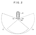
- FIG. 2 is a view for showing installation positions of the millimeter-wave radar systems 10R, 10L, which are included in the warning device 100 of the embodiment, in a host vehicle 60, and detectable areas 11R, 11L.
- the millimeter-wave radar system 10R is attached to a right corner of a rear end 60A of the host vehicle 60. Meanwhile, the millimeter-wave radar system 10L is attached to a left corner of the rear end 60A of the host vehicle 60.
- the millimeter-wave radar systems 10R, 10L are, for example, attached to side members in the rear of the host vehicle 60 or attached to an inner side of a rear bumper of the host vehicle 60.
- the millimeter-wave radar systems 10R, 10L are respectively attached to the right corner and the left corner of the rear end 60A of the host vehicle 60.
- the millimeter-wave radar systems 10R, 10L may respectively be attached to rear portions on a right side and a left side of the host vehicle 60 or may respectively be attached to a right end side of the rear end 60A and a left end side of the rear of the host vehicle 60.
- the millimeter-wave radar systems 10R, 10L each causes an electromagnetic wave to permeate the bumper, which is formed of a resin or the like, and be radiated to the right rear and the left rear of the vehicle, and detects a reflected wave, so as to detect a position, a moving direction, a speed of another vehicle or an obstacle at the right rear or the left rear of the vehicle.
- the radar section 20R is an example of the first detection section for detecting another vehicle that approaches from the right rear of the vehicle by using radar
- the radar section 20L is an example of the second detection section for detecting another vehicle approaching from the left rear of the vehicle by using the radar.
- the millimeter-wave radar systems 10R, 10L respectively have the detectable areas 11R, 11L that are shown in FIG. 2 .
- the detectable area 11R that is indicated by a dashed line is a fan-shaped area having an angle of approximately 170° from the right side to the rear with the right corner in the rear portion of the host vehicle 60 being a center.
- the detectable area 11L that is indicated by a chain line is a fan-shaped area having an angle of approximately 170° from the left side to the rear with the left corner in the rear portion of the host vehicle 60 being a center.
- the warning device 100 may detect another vehicle in an entire area that is covered by the detectable areas 11R, 11L that are shown in FIG. 2 or may detect another vehicle in a portion of the area.
- the millimeter-wave radar systems 10R, 10L each generates a modulation signal in which a triangular wave is modulated, outputs a transmission signal that is modulated to increase or lower a frequency according to a gradient of the triangular wave, and generates a beat signal for which a portion of the transmission signal is mixed with respect to a received signal.
- the millimeter-wave radar systems 10R, 10L each performs Fast Fourier Transform (FFT) processing or the like on the beat signal in each of an up section and a down section of a modulation cycle to generate frequency spectrum data, and searches a peak frequency at which reception wave intensity forms a peak from the frequency spectrum data.
- FFT Fast Fourier Transform
- the millimeter-wave radar systems 10R, 10L each obtains a distance D from the obstacle and a relative speed V from equations (1) to (6).
- a Doppler frequency based on the relative speed is set to fd
- a beat frequency in a section where the frequency is increased (the up section) is set to fb1
- the beat frequency in a section where the frequency is lowered (the down section) is set to fb2
- fr and fd can be obtained by the following equations (3) (4) if the beat frequencies fb1 and fb2 in the up section and the down section of the modulation cycle are separately measured. Then, once fr and fd are obtained, the distance D and the relative speed V between the host vehicle 60 and the obstacle can be obtained by the following equations (5) (6).
- C represents the speed of light
- fm represents a repetition frequency of the triangular wave as a source of the transmission signal
- ⁇ F represents a frequency shift width
- f 0 represents a center frequency of a modulation wave.
- fd fd ⁇ 1 - fb ⁇ 2 / 2
- an orientation of the obstacle can be calculated by the DBF.
- a radio wave that arrives from a direction of an angle ⁇ with respect to a direction of the center axis of the millimeter-wave radar systems 10R, 10L is received by an array antenna that includes element antennas #1, #2, #3 ... that are arranged at intervals d, a propagation path length of the radio wave in the element antenna #2 is longer than the propagation path length thereof in the element antenna #1 by d sin ⁇ .
- a phase of the radio wave that is received by the element antenna #2 is delayed from the phase of the radio wave that is received by the element antenna #1 by (2 ⁇ d sin ⁇ )/ ⁇ .
- ⁇ represents a wavelength of the radio wave. If this delay is corrected by a phase shifter, the radio wave from a ⁇ direction is received in the same phase by both of the element antennas, and thus directivity is set in the ⁇ direction.
- the DBF is a technique to create the directivity of the antenna by converting the phase and amplitude and by combining the reception wave of the each antenna element on the basis of such principles. Accordingly, the millimeter-wave radar systems 10R, 10L can obtain an orientation ⁇ of the obstacle.
- the millimeter-wave radar systems 10R, 10L can calculate the position of the obstacle with a specified position of the host vehicle as a reference, the moving direction of the obstacle with the center axis (that is, a traveling direction) of the host vehicle as a reference, a moving speed of the obstacle, and the like.
- a difference in a relative position in a fine period can be calculated, or a speed vector can be calculated with the relative speed V, an orientation angle ⁇ , and the speed of the host vehicle as parameters.
- the millimeter-wave radar systems 10R, 10L screen (sieve) the obstacles whose positions, moving directions, speeds, and the like have been calculated as described above on conditions of the reception wave intensity, the estimated size, the speed, and the like, thereby extracting a vehicle from the obstacles.
- the millimeter-wave radar systems 10R, 10L can obtain the position of another vehicle at the right rear or the left rear of the host vehicle, the moving direction thereof with the center axis of the host vehicle as the reference, the speed thereof, and the like.
- a description will hereinafter be made on the embodiment based on the premise of such a technique.
- a laser radar system As means for obtaining information such as the position, the speed, and the like of another vehicle, a laser radar system, a quasi-millimeter-wave radar system, or the like may be used instead of the millimeter-wave radar systems 10R, 10L.
- the position, the speed, and the like of another vehicle may be calculated by a method that does not use the Doppler effect.
- the speaker 40, the buzzer 41, the indicator 42, and the display device 43 that are shown in FIG. 1 are, for example, examples of the warning section that issues a warning.
- the speaker 40 is a speaker that is disposed in a cabin of the host vehicle and outputs a warning sound.
- the speaker 40 may also serve as a speaker that outputs audio and voice of a navigation system, or an exclusive speaker may be used for generating the warning sound of the warning device 100 of the embodiment, for example.
- the indicator 42 is attached to an inner mirror, an outer mirror, a combination meter, or the like and is turned on or blinked when the warning is issued.
- the display device 43 is a display section of the navigation system, for example, and turns on or blinks an icon, or the like when the warning is issued.
- the indicator 42 or the display device 43 may adopt a mode capable of indicating a right or left direction by an arrow or the like when another vehicle is detected, so as to allow the driver to recognize the arrival direction of another vehicle.
- the ECU 30R is a computer unit that includes a CPU as its center as well as a ROM, a RAM, and the like that are interconnected via a bus, for example, and also includes memories such as a hard disc drive (HDD) and an electrically erasable and programmable read only memory (EEPROM), an I/O port, a timer, a counter, and the like.
- a hard disc drive HDD
- EEPROM electrically erasable and programmable read only memory
- the ECU 30R receives output signals from switches and sensors such as the ignition switch 50, the vehicle speed sensor 52, the shift lever position sensor 54, the accelerator pedal operation amount sensor 56, and the like, or a status signal or the like that is output by the other ECU for controlling the vehicle by using these output signals.
- switches and sensors such as the ignition switch 50, the vehicle speed sensor 52, the shift lever position sensor 54, the accelerator pedal operation amount sensor 56, and the like, or a status signal or the like that is output by the other ECU for controlling the vehicle by using these output signals.
- the ECU 30R actuates the millimeter-wave radar systems 10R, 10L when the host vehicle is reversed from a parked state, outputs the warning sound from the speaker 40, and displays the warning that indicates the approach of another vehicle on the buzzer 41, the indicator 42, and the display device 43 when another vehicle that is detected by the millimeter-wave radar systems 10R, 10L is in a detection area on the right rear side or left rear side of the vehicle.
- Whether the host vehicle is in the "parked state” can be determined by setting such a condition that an ACC off signal is input from the ignition switch 50, that a signal input from the shift lever position sensor 54 indicates “P" (parking), and the like, for example.
- a condition that a vehicle speed signal that is input from the vehicle speed sensor 52 immediately before the ignition switch 50 is turned off is zero may be added to the above condition.
- Whether the host vehicle is "reversed” can be determined by setting such a condition that a signal input from the shift lever position sensor 54 indicates “R” (reverse) after a period of the above “parked state", or the like.
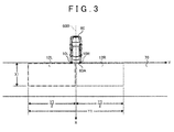
- FIG. 3 shows an example of detection areas 12R, 12L that are set by the ECU 30R when the host vehicle 60 is reversed from a state that it is parked perpendicular to a traveling lane.
- the detection areas 12R, 12L are areas in the detectable areas 11R, 11L shown in FIG. 2 that are used by the warning device 100 to detect another vehicle, and are set by the ECU 30R.
- the detection area 12R is indicated by a dashed line
- the detection area 12L is indicated by a chain line.
- an X-axis with a rear direction of the host vehicle 60 being a positive direction and a Y-axis that is orthogonal to the X-axis at the rear end 60A of the host vehicle 60 are defined on a center axis 60B of the host vehicle 60.
- a positive direction of the Y-axis is on the right side in FIG. 3 .
- a border between the detection area 12R and the detection area 12L is on the center axis 60B.
- an area that is a sum of the detection areas 12R, 12L corresponds to an area having a width X1 in the positive direction of the X-axis from the rear end 60A of the host vehicle 60 and a width Y1 on both right and left sides from the center axis 60B.
- the detection area 12R is an area that is on the right side of the center axis 60B and has a width Y1/2
- the detection area 12L is an area that is on the left side of the center axis 60B and has a width Y1/2.
- the detection area 12R is an area that is located at the right rear of the host vehicle 60 and detected by the millimeter-wave radar system 10R as the first detection section.
- the detection area 12L is an area that is located at the left rear of the host vehicle 60 and detected by the millimeter-wave radar system 10L as the second detection section.
- the traveling lane 70 may be a traveling lane in a parking lot of a store or the like, for example, or may be a road.
- FIG. 4A , FIG. 4B , and FIG. 5 a description will be made on an assumption that the warning device of the comparative example is installed in the host vehicle 60.
- the warning device of the comparative example has a same configuration as the warning device 100 of the embodiment shown in FIG. 1 , it is different from the warning device 100 of the embodiment in a point that a problem shown in FIG. 5 is raised.
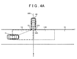
- FIG. 4A is a view for showing a state of detecting another vehicle 71 that approaches from the left side at the rear of the host vehicle 60 in which the warning device of the comparative example is installed.
- FIG. 4B is a view for detecting another vehicle 72 that approaches from the right side at the rear of the host vehicle 60 in which the warning device of the comparative example is installed.
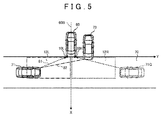
- FIG. 5 is a view for showing a state that another vehicle 71 approaches from the left rear in a state that another vehicle 73 is parked on the right of the host vehicle 60 in which the warning device of the comparative example is installed.
- the millimeter-wave radar system 10L receives the reflected wave from another vehicle 71.
- the warning device of the comparative example detects another vehicle 71 that approaches from the left rear of the host vehicle 60.
- the driver of the host vehicle 60 in which the warning device of the comparative example is installed is informed of the approach of another vehicle 71 from the left rear of the host vehicle 60 by the warning through the speaker 40, the buzzer 41, the indicator 42, and the display device 43.
- the millimeter-wave radar system 10R receives the reflected wave from another vehicle 72.
- the warning device of the comparative example detects another vehicle 72 that approaches from the right rear of the host vehicle 60.
- the driver of the host vehicle 60 in which the warning device of the comparative example is installed is informed of the approach of another vehicle 72 from the right rear of the host vehicle 60 by the warning through the speaker 40, the buzzer 41, the indicator 42, and the display device 43.
- another vehicle 73 is parked in a parking space on the right of a parking space where the host vehicle 60 in which the warning device of the comparative example is installed is parked, and another vehicle 71 approaches from the left rear of the host vehicle 60.
- the millimeter-wave radar system 10L receives a reflected wave 81 that is reflected by another vehicle 71 through a path indicated by the dashed line
- the millimeter-wave radar system 10R receives a reflected wave 82 that is reflected by another vehicle 71 and is then reflected by a left side face of another vehicle 73 through a path indicated by the chain line.
- the path of the reflected wave 82 indicated by the chain line is multipath with respect to the path of the reflected wave 81 as an original path.
- the warning device of the comparative example detects the approach of another vehicle 71G from the right rear of the host vehicle 60 immediately after detecting the approach of another vehicle 71 from the left rear of the host vehicle 60.
- Another vehicle 71G in this case is a ghost that is generated when the reflected wave 82 reflected by another vehicle 71 is further reflected by the left side face of another vehicle 73 that is parked on the right of the host vehicle 60, and thus, a non-existent vehicle is faultily detected.
- Such a ghost may also be detected when another vehicle 73 is parked on the right side of the host vehicle 60 with one or plural parking spaces being interposed therebetween.
- such a ghost may be detected when another vehicle 73 is parked in a parking space on the left of the host vehicle 60.
- such a ghost may be detected when there is a wall of a building or the like on the right or left of the host vehicle 60.
- the warning device of the comparative example makes false detection of the ghost when another vehicle 73 is parked on the right or left of the host vehicle 60 or when the multipath is generated due to the wall of the building.
- Another vehicle 71G that is detected as the ghost is detected as a vehicle that satisfies the condition of the same speed as another vehicle 71, the specified time difference by the multipath, the arrival direction that is substantially and linearly symmetrical to the center axis of the host vehicle 60, or the like.
- FIG. 6A is a view for showing a functional block that is included in the ECU 30R of the warning device of the embodiment.
- FIG. 6B is a view for showing a functional block that is included in the ECU 30L of the warning device of the embodiment.
- FIG. 7 is a view for showing a warning line that is used for calculation of an estimated crossing time.
- the warning device 100 of the embodiment extends the warning of a first other vehicle.
- the warning is extended from a time at which a second other vehicle is detected to a time at which the estimated crossing time (ECT) with the second other vehicle ends, for example.
- the ECU 30R includes a primary control section 31R, a vehicle detection section 32R, an ECT calculation section 33R, and a warning section 34R.
- the ECU 30L includes a primary control section 31L, a vehicle detection section 32L, and an ECT calculation section 33L.
- the primary control section 31R is a processing section that controls overall internal processing of the ECU 30R and performs determination processing, which will be described below.
- the vehicle detection section 32R detects presence or absence of another vehicle and an orientation of another vehicle with respect to the host vehicle on the basis of a signal input from the radar section 20R.
- the presence or absence of another vehicle is determined by determining moving one of the obstacles that are detected by the signal input from the radar section 20R as another vehicle.
- the orientation ( ⁇ ) of another vehicle can be calculated by the DBF as described above.
- the ECT calculation section 33R calculates a time that is taken until a trajectory of the host vehicle 60 crosses a trajectory of another vehicle in a case where the host vehicle 60 is reversed and another vehicle moves in the moving direction.
- the ECT calculation section 33R calculates a time required for a warning line 13R that virtually extends to the rear of the host vehicle 60 crosses another vehicle 71 that is located in the detection area 12R as the estimated crossing time (ECT).
- the estimated crossing time (ECT) is calculated by dividing a distance between another vehicle 71 and an alarming line 13R by the relative speed between another vehicle 71 and the host vehicle 60.
- the warning section 34R orders the speaker 40, the buzzer 41, the indicator 42, and the display device 43 to issue the warning when the primary control section 31R determines that the issuance of the warning is necessary.
- a duration to issue the warning corresponds to the estimated crossing time (ECT) that is calculated by the ECT calculation section 33R.
- the primary control section 31L controls overall internal processing of the ECU 30L and transmits the presence or absence and the orientation of another vehicle, which are detected by the vehicle detection section 32L, and the estimated crossing time (ECT), which is calculated by the ECT calculation section 33R, to the primary control section 31R of the ECU 30R.
- ECT estimated crossing time
- the vehicle detection section 32L detects the presence or absence of another vehicle and the orientation of another vehicle with respect to the host vehicle on the basis of a signal input from the radar section 20L.
- the presence or absence of another vehicle is determined by determining moving one of the obstacles that are detected by the signal input from the radar section 20L as another vehicle.
- the orientation ( ⁇ ) of another vehicle can be calculated by the DBF as described above.
- the ECT calculation section 33L calculates a time that is taken until the trajectory of the host vehicle 60 crosses a trajectory of another vehicle in a case where the host vehicle 60 is reversed and another vehicle moves in the moving direction.
- the ECT calculation section 33L calculates a time required for a warning line 13L that virtually extends to the rear of the host vehicle 60 crosses another vehicle 71 that is located in the detection area 12L as the estimated crossing time (ECT).
- the estimated crossing time (ECT) is calculated by dividing a distance between another vehicle and an alarming line 13L by the relative speed between another vehicle and the host vehicle 60.
- the estimated crossing time that is calculated by the ECT calculation section 33L is transmitted to the primary control section 31R and is used as the duration to issue the warning when the warning is issued on another vehicle that arrives from the left rear of the host vehicle 60.
- the primary control section 31R determines whether the other one of the millimeter-wave radar systems 10R, 10L detects the second other vehicle. For example, after the millimeter-wave radar system 10R detects the first other vehicle that approaches the host vehicle 60 from the right rear, the primary control section 31R determines whether the millimeter-wave radar system 10L detects the second other vehicle that approaches the host vehicle 60 from the left rear. The primary control section 31R makes the determination of whether the second other vehicle that approaches the host vehicle 60 from the left rear is detected on the basis of information that is transmitted from the primary control section 31L in the ECU 30L of the millimeter-wave radar system 10L.
- the primary control section 31R determines whether the millimeter-wave radar system 10R detects the second other vehicle that approaches the host vehicle 60 from the right rear.
- the primary control section 31R extends the issuance of the warning of the first other vehicle when the other of the millimeter-wave radar systems 10R, 10L detects the second other vehicle within the specified time after one of the millimeter-wave radar systems 10R, 10L detects the first other vehicle that approaches the host vehicle 60.
- the primary control section 31R extends the warning of the first other vehicle from the time at which the second other vehicle is detected until the estimated crossing time (ECT) of the second other vehicle elapses.
- the duration to extend the warning by the primary control section 31R corresponds to a duration that is obtained by subtracting a time at which the issuance of the warning of the first other vehicle ends in a case where the warning is not extended from a time that is obtained by adding the estimated crossing time (ECT) of the second other vehicle to the time at which the second other vehicle is detected.
- FIG. 8 is a flowchart for illustrating processing that is executed by the ECU 30R of the warning device of the embodiment.
- the processing in this flowchart is processing that is executed by the primary control section 31R of the ECU 30R in the warning device of the embodiment.
- the primary control section 31R starts processing (START) when the host vehicle 60 starts being reversed from the parked state.
- the primary control section 31R recognizes that the host vehicle 60 starts being reversed from the parked state since the signal input from the shift lever position sensor 54 indicates "R" (REVERSE).
- the primary control section 31R determines whether another vehicle is detected (a step S1).
- the detection of another vehicle can be performed on the basis of whether the detection signal is received from the radar section 20R or 20L.
- the primary control section 31R transmits a warning issuing command to the warning section 34R (a step S2).
- the warning section 34R orders the speaker 40, the buzzer 41, the indicator 42, and the display device 43 to issue the warning.
- the duration to issue the warning corresponds to the estimated crossing time (ECT) that is calculated by the ECT calculation section 33R or 33L.
- the primary control section 31R determines whether the other one of the millimeter-wave radar systems 10R, 10L detects the second other vehicle (a step S3). In other words, in the step S3, the primary control section 31R determines whether the millimeter-wave radar system (10R or 10L) that is on the opposite side of the right or left from another vehicle that has been detected in the step S1 detects the second other vehicle.
- the primary control section 31R determines whether the second other vehicle is detected within the specified time after the detection of the first other vehicle (a step S4).
- the determination of the step S4 is made by calculating a difference between a detection time of the first other vehicle and a detection time of the second other vehicle.
- the primary control section 31R extends the warning of the first other vehicle (a step S5).
- the primary control section 31R extends the warning of the first other vehicle from the time at which the second other vehicle is detected until the estimated crossing time (ECT) of the second other vehicle that is calculated by the ECT calculation section 33R or 33L elapses.
- ECT estimated crossing time
- the duration to extend the warning by the primary control section 31R corresponds to the duration that is obtained by subtracting the time at which the issuance of the warning of the first other vehicle ends in the case where the warning is not extended from the time that is obtained by adding the estimated crossing time (ECT) of the second other vehicle to the time at which the second other vehicle is detected.
- the primary control section 31R determines whether the host vehicle 60 is being reversed (a step S6). While the detection of another vehicle is continuously required if the host vehicle is being reversed, the detection of another vehicle is not required if the host vehicle is not being reversed. Thus, the determination of whether it is being reversed is made.
- the primary control section 31R determines whether the host vehicle 60 is being reversed on the basis of whether the signal input from the shift lever position sensor 54 indicates "R" (reverse). Being reversed refers to a state in which a shift lever position is in "R" (reverse) and does not indicate that the host vehicle 60 is actually being reversed or not.
- the flow returns to the step S1, and the processing in the step S1 is executed.
- the primary control section 31R determines that the host vehicle 60 is not being reversed (the step S6: NO)
- a series of the processing is terminated (END). For example, it is because there is no need to monitor another vehicle at the rear of the host vehicle 60 once the host vehicle 60 starts traveling forward, for example.
- step S1 the step S1: NO
- the primary control section 31R proceeds with the flow to the step S6. This is to make a determination on whether the process should return to the step S1 to detect another vehicle again or the series of processing should be terminated by determining whether the host vehicle 60 keeps being reversed.
- the primary control section 31R proceeds with the flow to the step S6. This is to make the determination on whether the process should return to the step S1 to detect another vehicle again or the series of processing should be terminated by determining whether the host vehicle 60 keeps being reversed.
- the primary control section 31R makes a determination of NO in the step S3.
- the step S6 the step S6: YES
- the flow returns to the step S1, and the second other vehicle that is detected in the same direction as the first other vehicle is detected as the first other vehicle in the step S1.
- the primary control section 31R determines in the step S4 that the second other vehicle is not detected within the specified time after the detection of the first other vehicle, the flow returns to the step S2, and the warning issuing command is transmitted to the warning section 34R (the step S2).
- the warning section 34R orders the speaker 40, the buzzer 41, the indicator 42, and the display device 43 to issue the warning.
- the second other vehicle is detected from the opposite side of the first other vehicle and another vehicle and where the second other vehicle is detected after the specified time elapses from the time at which the first other vehicle is detected, it is determined that the second other vehicle is not the ghost of the first other vehicle but the first other vehicle that approaches the host vehicle 60 independently of the first vehicle. Accordingly, the warning is issued as in the case where another vehicle is detected in the step S 1.
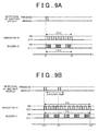
- FIG. 9A and FIG. 9B Next, an operation to extend the warning by the warning device 100 of the embodiment will be described by using FIG. 9A and FIG. 9B .
- FIG. 9A and FIG. 9B are timing charts for showing the operation to extend the warning by the warning device 100 of the embodiment.
- FIG. 9A and FIG. 9B show presence or absence of the detection of another vehicle, on/off of the indicator 42, and on/off of the buzzer 41.
- a horizontal axis is a time axis, and the right direction is a positive direction of the time axis.
- FIG. 9A shows an operation in a case where, after the first other vehicle is detected at a time t1, the second other vehicle is not detected.
- the primary control section 31R transmits the warning issuing command to the warning section 34R, thereby actuating the indicator 42 to be repeatedly turned on/off and also actuating the buzzer 41 to be repeatedly turned on/off.
- the duration to issue the warning corresponds to the estimated crossing time (ECT) that is calculated by the ECT calculation section 33R or 33L.
- the indicator 42 is repeatedly blinked for 2.5 seconds, and the buzzer 41 also repeatedly sounds for 2.5 seconds.
- the actuation of the indicator 42 is terminated at a time t2 that is 2.5 seconds after the time t1, and sounding of the buzzer 41 is also terminated at the time t2.
- FIG. 9B shows an operation in a case where the second other vehicle is detected on the opposite side from the first other vehicle at a time t12 within a specified time from a time t11 at which the first other vehicle is detected.
- the primary control section 31R transmits the warning issuing command to the warning section 34R, thereby actuating the indicator 42 to be repeatedly turned on/off and also actuating the buzzer 41 to be repeatedly turned on/off.
- the duration to issue the warning corresponds to the estimated crossing time (ECT) of the first other vehicle that is calculated by the ECT calculation section 33R or 33L.
- the time t11 shown in FIG. 9B is the same time as the time t1 shown in FIG. 9A for convenience of the description, and the estimated crossing time (ECT) calculated for the first other vehicle is 2.5 seconds as in the case shown in FIG. 9A .
- the primary control section 31R extends the warning of the first other vehicle. Accordingly, the indicator 42 continues to be blinked until a time t13, and the buzzer 41 also stops sounding at the time t13.
- the warning is extended until the time t13 that is obtained by adding the estimated crossing time (ECT), which is calculated for the second other vehicle by the ECT calculation section 33R or 33L, to the time t12 at which the second other vehicle is detected.
- the estimated crossing time (ECT) that is calculated for the second other vehicle is a time between the time t12 and the time t13.
- the duration to extend the warning just as described corresponds to the duration that is obtained by subtracting the time t2 (see FIG. 9A ) at which the issuance of the warning of the first other vehicle ends in a case where the warning is not extended from the time t13 that is obtained by adding the estimated crossing time (ECT) of the second other vehicle to the time t12 at which the second other vehicle is detected.
- ECT estimated crossing time
- This duration is the duration represented by t13 - t12.
- the extended warning is stopped at the time t13.
- the estimated crossing time (ECT) of the second other vehicle that is calculated for the second other vehicle by the ECT calculation section 33R or 33L is a time that corresponds to a time difference between the time t12 and the time t13.
- the specified time shown in FIG. 9B is a specified time used in the above step S4 after the first other vehicle is detected, and may be set to an appropriate value by an experiment or the like.
- the specified time may be set to 2 seconds.
- the specified time is set to a shorter time than the duration to issue the warning of the first other vehicle. This is to extend the warning of the second other vehicle that is detected on the opposite side from the first other vehicle while the warning of the first other vehicle is being issued.
- the warning device 100 of the embodiment when another vehicle is detected on the opposite side from the first other vehicle within the specified time after the first other vehicle is detected, the warning of the first other vehicle is extended.
- the second other vehicle is not the ghost but the actual vehicle, it is possible to prevent in advance contact of the reversed host vehicle 60 with the second other vehicle.
- FIG. 9B a mode in which both of the blinking of the indicator 42 and the sounding of the buzzer 41 are extended is described; however, the warning may only be extended in either one of the indicator 42 and the buzzer 41.
- FIG. 10 is a timing chart for showing the operation to extend the warning by the warning device of a modified example of the embodiment.
- the primary control section 31R extends the warning of the first other vehicle and orders the buzzer 41 to sound until the time t13.
- the sounding of the buzzer 41 is extended for 1.5 seconds to inform the driver of the host vehicle 60 of the presence of the second other vehicle.
- the warning may be issued by output of the warning sound from the speaker 40, the lighting or blinking of the icon on the display device 43, and the like.
- the warning may be issued by any one of the output of the warning sound from the speaker 40, the sounding of the buzzer 41, the blinking of the indicator 42, the lighting or blinking of the icon on the display device 43, and the like, or may be issued by arbitrarily combining any of them.
- the approach from both of the right and left may be displayed to alert the driver to the arrival of another vehicle from the opposite side at a moment when the second other vehicle is detected at the time t12. For example, if the second other vehicle is detected at the time t12 while the first other vehicle approaches from the right rear of the host vehicle and the indicator 42 or the display device 43 informs the driver of the host vehicle 60 of the approach from the right side, the approach from the left side may be displayed in addition to the display of the approach from the right side.
- a blinking pattern or the like of the indicator 42 or the display device 43 may be changed, for example.
- the approach from both of the right and left may be displayed at a moment when the first other vehicle is detected.
- the indicator 42 may be positioned in the inner mirror, the outer mirror, the combination meter, or the like, and more specifically, may be attached to a mirror surface of the outer mirror, a housing of the outer mirror (for example, a turn signal), a display in the cabin, a pillar in the cabin (for example, A, B, or C pillar), an instrument panel, or the like.
- a housing of the outer mirror for example, a turn signal
- a display in the cabin for example, a pillar in the cabin (for example, A, B, or C pillar), an instrument panel, or the like.
- the warning only on the direction of the first other vehicle may be extended, or the warning on the direction of the second other vehicle that can be the ghost may also be extended. If the plurality of second other vehicles, one or some of which can be the ghosts, are present, the warnings on all the directions may be extended.
- the primary control section 31R may extend the warning of the first other vehicle from the time at which the estimated crossing time (ECT) of the second other vehicle is calculated by the ECT calculation section 33R or 33L until the estimated crossing time (ECT) of the second other vehicle elapses.
- the warning may be extended by adding a specified spare time to the estimated crossing time (ECT).
- a specified spare time may be set to a value that is obtained by an experiment or the like, for example.
- the duration to extend the warning is not limited to the estimated crossing time (ECT) but may be set to a duration that is obtained by an experiment or the like.
Landscapes
- Engineering & Computer Science (AREA)
- Radar, Positioning & Navigation (AREA)
- Remote Sensing (AREA)
- Physics & Mathematics (AREA)
- General Physics & Mathematics (AREA)
- Computer Networks & Wireless Communication (AREA)
- Electromagnetism (AREA)
- Human Computer Interaction (AREA)
- Mechanical Engineering (AREA)
- Traffic Control Systems (AREA)
- Radar Systems Or Details Thereof (AREA)
Applications Claiming Priority (1)
| Application Number | Priority Date | Filing Date | Title |
|---|---|---|---|
| PCT/JP2012/053160 WO2013118301A1 (fr) | 2012-02-10 | 2012-02-10 | Dispositif d'avertissement |
Publications (2)
| Publication Number | Publication Date |
|---|---|
| EP2814018A1 true EP2814018A1 (fr) | 2014-12-17 |
| EP2814018A4 EP2814018A4 (fr) | 2015-08-12 |
Family
ID=48947102
Family Applications (1)
| Application Number | Title | Priority Date | Filing Date |
|---|---|---|---|
| EP12868170.7A Withdrawn EP2814018A4 (fr) | 2012-02-10 | 2012-02-10 | Dispositif d'avertissement |
Country Status (4)
| Country | Link |
|---|---|
| US (1) | US20140354450A1 (fr) |
| EP (1) | EP2814018A4 (fr) |
| CN (1) | CN104106102A (fr) |
| WO (1) | WO2013118301A1 (fr) |
Cited By (3)
| Publication number | Priority date | Publication date | Assignee | Title |
|---|---|---|---|---|
| DE102016215505A1 (de) * | 2016-08-18 | 2018-02-22 | Continental Automotive Gmbh | Geisterzielerkennung bei einem Radarsystem in einem Fahrzeug. |
| EP3438947A4 (fr) * | 2016-03-31 | 2019-07-03 | Furukawa Electric Co., Ltd. | Dispositif de contrôle et procédé de contrôle |
| EP3576073A3 (fr) * | 2018-06-01 | 2020-03-18 | Mazda Motor Corporation | Système d'alarme pour véhicule |
Families Citing this family (15)
| Publication number | Priority date | Publication date | Assignee | Title |
|---|---|---|---|---|
| JP5737411B2 (ja) * | 2011-09-12 | 2015-06-17 | トヨタ自動車株式会社 | 警報装置 |
| US10252663B2 (en) * | 2014-06-02 | 2019-04-09 | Denso Corporation | Headlight control apparatus |
| JP6394138B2 (ja) * | 2014-07-16 | 2018-09-26 | 株式会社デンソー | 車載レーダ装置および報知システム |
| US10481696B2 (en) | 2015-03-03 | 2019-11-19 | Nvidia Corporation | Radar based user interface |
| US10113877B1 (en) * | 2015-09-11 | 2018-10-30 | Philip Raymond Schaefer | System and method for providing directional information |
| JP6583527B2 (ja) * | 2016-02-22 | 2019-10-02 | 株式会社リコー | 画像処理装置、撮像装置、移動体機器制御システム、画像処理方法、及びプログラム |
| JP6096971B1 (ja) * | 2016-08-25 | 2017-03-15 | ムサシノ機器株式会社 | 高位液面警報装置 |
| WO2019181448A1 (fr) * | 2018-03-19 | 2019-09-26 | 日立オートモティブシステムズ株式会社 | Dispositif radar |
| KR102589934B1 (ko) * | 2018-09-13 | 2023-10-17 | 현대모비스 주식회사 | 경고 조건 조정 장치 및 방법 |
| JP2022028092A (ja) * | 2018-12-20 | 2022-02-15 | ソニーグループ株式会社 | 車両制御装置、車両制御方法、プログラム、及び、車両 |
| JP7205262B2 (ja) * | 2019-02-01 | 2023-01-17 | 株式会社デンソー | 警報装置 |
| JP7192600B2 (ja) * | 2019-03-20 | 2022-12-20 | 株式会社デンソー | 警報装置 |
| CN113135193B (zh) * | 2021-04-16 | 2024-02-13 | 阿波罗智联(北京)科技有限公司 | 输出预警信息的方法、设备、存储介质及程序产品 |
| JP7723349B2 (ja) * | 2022-04-28 | 2025-08-14 | トヨタ自動車株式会社 | 運転支援装置 |
| EP4358064A1 (fr) | 2022-10-19 | 2024-04-24 | Continental Autonomous Mobility Germany GmbH | Système de détection d'objet de véhicule et procédé de détection d'un objet cible dans une zone de détection située derrière et latéralement d'un véhicule sujet |
Family Cites Families (16)
| Publication number | Priority date | Publication date | Assignee | Title |
|---|---|---|---|---|
| GB2328819A (en) * | 1997-08-30 | 1999-03-03 | Ford Motor Co | Antenna cluster for vehicle collision warning system |
| DE19843564A1 (de) * | 1998-09-23 | 2000-03-30 | Bosch Gmbh Robert | Warneinrichtung für ein Kraftfahrzeug |
| JP4100026B2 (ja) * | 2002-04-11 | 2008-06-11 | 三菱自動車工業株式会社 | 発進支援装置 |
| DE10352800A1 (de) * | 2003-11-12 | 2005-06-23 | Robert Bosch Gmbh | Vorrichtung zur Detektion von bewegten Objekten |
| JP4440708B2 (ja) * | 2004-06-04 | 2010-03-24 | トヨタ自動車株式会社 | 車両の制御装置 |
| US7248215B2 (en) | 2004-12-30 | 2007-07-24 | Valeo Raytheon Systems, Inc | Beam architecture for improving angular resolution |
| CN101140704A (zh) * | 2006-09-08 | 2008-03-12 | 松下电器产业株式会社 | 方向检测装置 |
| US8552848B2 (en) * | 2007-08-16 | 2013-10-08 | Ford Global Technologies, Llc | System and method for combined blind spot detection and rear crossing path collision warning |
| US20090072957A1 (en) * | 2007-09-14 | 2009-03-19 | Honeywell International Inc. | Radio frequency proximity sensor and sensor system |
| US8207835B2 (en) * | 2008-10-19 | 2012-06-26 | Micha Schwartz | Vehicle safety device |
| US20100201508A1 (en) * | 2009-02-12 | 2010-08-12 | Gm Global Technology Operations, Inc. | Cross traffic alert system for a vehicle, and related alert display method |
| US7978096B2 (en) * | 2009-04-28 | 2011-07-12 | Ford Global Technologies, Llc | Parking angle determination and cross traffic alert |
| US8232872B2 (en) * | 2009-12-03 | 2012-07-31 | GM Global Technology Operations LLC | Cross traffic collision alert system |
| JP5414588B2 (ja) * | 2010-03-24 | 2014-02-12 | 株式会社東芝 | 車両運転支援用処理装置及び車両運転支援装置 |
| US20120041632A1 (en) * | 2010-08-12 | 2012-02-16 | Robert Bosch Gmbh | Combined lane change assist and rear, cross-traffic alert functionality |
| US8688365B2 (en) * | 2012-01-18 | 2014-04-01 | International Business Machines Corporation | Method and system for detection of motor vehicle movement to avoid collisions |
-
2012
- 2012-02-10 CN CN201280069256.7A patent/CN104106102A/zh active Pending
- 2012-02-10 WO PCT/JP2012/053160 patent/WO2013118301A1/fr not_active Ceased
- 2012-02-10 EP EP12868170.7A patent/EP2814018A4/fr not_active Withdrawn
- 2012-02-10 US US14/376,641 patent/US20140354450A1/en not_active Abandoned
Cited By (4)
| Publication number | Priority date | Publication date | Assignee | Title |
|---|---|---|---|---|
| EP3438947A4 (fr) * | 2016-03-31 | 2019-07-03 | Furukawa Electric Co., Ltd. | Dispositif de contrôle et procédé de contrôle |
| DE102016215505A1 (de) * | 2016-08-18 | 2018-02-22 | Continental Automotive Gmbh | Geisterzielerkennung bei einem Radarsystem in einem Fahrzeug. |
| EP3576073A3 (fr) * | 2018-06-01 | 2020-03-18 | Mazda Motor Corporation | Système d'alarme pour véhicule |
| US10745031B2 (en) | 2018-06-01 | 2020-08-18 | Mazda Motor Corporation | Alarm system for vehicle |
Also Published As
| Publication number | Publication date |
|---|---|
| CN104106102A (zh) | 2014-10-15 |
| EP2814018A4 (fr) | 2015-08-12 |
| US20140354450A1 (en) | 2014-12-04 |
| WO2013118301A1 (fr) | 2013-08-15 |
Similar Documents
| Publication | Publication Date | Title |
|---|---|---|
| EP2814018A1 (fr) | Dispositif d'avertissement | |
| JP5737411B2 (ja) | 警報装置 | |
| US11022674B2 (en) | Vehicle surroundings monitoring apparatus | |
| US10011278B2 (en) | Collision avoidance system | |
| JP5042558B2 (ja) | レーダ装置 | |
| EP2701135B1 (fr) | Dispositif d'alerte de périphérie d'un véhicule | |
| JP5628518B2 (ja) | 自動車のレーダシステム、およびレーダシステムに対する物体の速度および距離を決定する方法 | |
| US5467072A (en) | Phased array based radar system for vehicular collision avoidance | |
| CN102066970B (zh) | 具有正面和侧面辐射的雷达传感器 | |
| US11136013B2 (en) | Vehicle control apparatus and vehicle control method | |
| JP5904280B2 (ja) | 車両の警報装置 | |
| JP2014227000A (ja) | 車両制御装置、その方法およびそのプログラム | |
| US10759342B2 (en) | Apparatus and method for controlling collision alert | |
| JP2009281862A (ja) | レーダー装置の軸調整方法および軸調整装置 | |
| WO2020084805A1 (fr) | Dispositif et procédé de notification | |
| JP2009074804A (ja) | 物体検出装置 | |
| JPH08327731A (ja) | レーダによる方位検出方法及び方位検出レーダ装置及び自動車用衝突防止装置 | |
| JP2008152389A (ja) | 車両用周辺監視装置 | |
| JP2002131425A (ja) | レーダ装置、車載用レーダ装置並びに衝突防止システム | |
| JP5604179B2 (ja) | 物体検知装置 | |
| JP4684876B2 (ja) | レーダー装置及びレーダー装置の対象物検出方法 | |
| JPWO2013118301A1 (ja) | 警報装置 | |
| CN113525401A (zh) | 辅助汽车驾驶的预警方法及毫米波雷达系统 | |
| JP2020201118A (ja) | 車両用物体検出装置 | |
| JP2011220779A (ja) | 障害物検出装置 |
Legal Events
| Date | Code | Title | Description |
|---|---|---|---|
| PUAI | Public reference made under article 153(3) epc to a published international application that has entered the european phase |
Free format text: ORIGINAL CODE: 0009012 |
|
| 17P | Request for examination filed |
Effective date: 20140731 |
|
| AK | Designated contracting states |
Kind code of ref document: A1 Designated state(s): AL AT BE BG CH CY CZ DE DK EE ES FI FR GB GR HR HU IE IS IT LI LT LU LV MC MK MT NL NO PL PT RO RS SE SI SK SM TR |
|
| AX | Request for extension of the european patent |
Extension state: BA ME |
|
| DAX | Request for extension of the european patent (deleted) | ||
| RA4 | Supplementary search report drawn up and despatched (corrected) |
Effective date: 20150715 |
|
| RIC1 | Information provided on ipc code assigned before grant |
Ipc: G08G 1/16 20060101AFI20150709BHEP |
|
| STAA | Information on the status of an ep patent application or granted ep patent |
Free format text: STATUS: THE APPLICATION IS DEEMED TO BE WITHDRAWN |
|
| 18D | Application deemed to be withdrawn |
Effective date: 20160211 |