EP2814046A2 - Vorrichtung zum Verhindern von Lecks elektromagnetischer Wellen - Google Patents
Vorrichtung zum Verhindern von Lecks elektromagnetischer Wellen Download PDFInfo
- Publication number
- EP2814046A2 EP2814046A2 EP14169629.4A EP14169629A EP2814046A2 EP 2814046 A2 EP2814046 A2 EP 2814046A2 EP 14169629 A EP14169629 A EP 14169629A EP 2814046 A2 EP2814046 A2 EP 2814046A2
- Authority
- EP
- European Patent Office
- Prior art keywords
- resonator
- conductive
- disposed
- conductive object
- loop
- Prior art date
- Legal status (The legal status is an assumption and is not a legal conclusion. Google has not performed a legal analysis and makes no representation as to the accuracy of the status listed.)
- Withdrawn
Links
Images


Classifications
-
- H—ELECTRICITY
- H02—GENERATION; CONVERSION OR DISTRIBUTION OF ELECTRIC POWER
- H02J—ELECTRIC POWER NETWORKS; CIRCUIT ARRANGEMENTS OR SYSTEMS FOR SUPPLYING OR DISTRIBUTING ELECTRIC POWER; SYSTEMS FOR STORING ELECTRIC ENERGY
- H02J50/00—Circuit arrangements or systems for wireless supply or distribution of electric power
- H02J50/70—Circuit arrangements or systems for wireless supply or distribution of electric power involving the reduction of electric, magnetic or electromagnetic leakage fields
-
- H—ELECTRICITY
- H01—ELECTRIC ELEMENTS
- H01F—MAGNETS; INDUCTANCES; TRANSFORMERS; SELECTION OF MATERIALS FOR THEIR MAGNETIC PROPERTIES
- H01F27/00—Details of transformers or inductances, in general
- H01F27/34—Special means for preventing or reducing unwanted electric or magnetic effects, e.g. no-load losses, reactive currents, harmonics, oscillations, leakage fields
- H01F27/36—Electric or magnetic shields or screens
- H01F27/363—Electric or magnetic shields or screens made of electrically conductive material
-
- H—ELECTRICITY
- H01—ELECTRIC ELEMENTS
- H01F—MAGNETS; INDUCTANCES; TRANSFORMERS; SELECTION OF MATERIALS FOR THEIR MAGNETIC PROPERTIES
- H01F38/00—Adaptations of transformers or inductances for specific applications or functions
- H01F38/14—Inductive couplings
-
- H—ELECTRICITY
- H02—GENERATION; CONVERSION OR DISTRIBUTION OF ELECTRIC POWER
- H02J—ELECTRIC POWER NETWORKS; CIRCUIT ARRANGEMENTS OR SYSTEMS FOR SUPPLYING OR DISTRIBUTING ELECTRIC POWER; SYSTEMS FOR STORING ELECTRIC ENERGY
- H02J50/00—Circuit arrangements or systems for wireless supply or distribution of electric power
- H02J50/10—Circuit arrangements or systems for wireless supply or distribution of electric power using inductive coupling
- H02J50/12—Circuit arrangements or systems for wireless supply or distribution of electric power using inductive coupling of the resonant type
Definitions
- An embodiment described herein relates to a leakage preventing device of electromagnetic wave.
- a wireless power transmitting system which performs non-contact charging using a transmission/reception antenna of microwaves of 2.45 GHz for instance.
- the system includes a transmission antenna which outputs microwaves from an output surface, a reception antenna which is disposed at a position opposed to the output surface during transmission and receives the microwaves outputted by the transmission antenna on an input surface, and a shield part which electromagnetically shields a space between the transmission antenna and the reception antenna from the outside.
- the shield part is configured as the one for which a brush-like conductive object formed by bundling many wire-like or rod-like conductors is disposed in an area surrounding the output surface of the transmission antenna.
- a magnetic field distribution in the case of providing a metal plate respectively on the upper resonator and under the lower resonator and surrounding the upper and lower resonators by a metal shield having a cross section of a square-shaped ring is considered. It is assumed that there is no gap between the lower metal plate and the metal shield but there is a gap of 5 mm between the upper metal plate and the metal shield.
- the surrounding magnetic field distribution in this case becomes the magnetic field distribution with a small difference compared to the case that there is no metal shield having the cross section of the square-shaped ring.
- a magnetic field in the case that there is the metal shield has the reduction effect of about one third of the magnetic field in the case that there is no metal shield, that is a little less than -10 dB.
- a conventional technology has a problem that electromagnetic waves leak when there is a gap by recesses and projections under a vehicle body or a dielectric layer by a plastic casing.
- the leakage preventing device includes: a first conductor plate and first and second conductive objects.
- the first conductor plate is provided on a first side of the first resonator, the first side being an opposite side of a second side of the first conductor plate where the first resonator is opposed to the second resonator.
- the first and second conductive objects are electrically connectable to the first conductor plate at first ends and be electrically connectable to a second conductor plate at second ends respectively.
- the second conductor plate is provided on a third side of the second resonator.
- the third side is an opposite side of a fourth side of the second resonator where the second resonator is opposed to the first resonator.
- the first and second conductive objects form a conductive loop surrounding a periphery of the first and second resonators together with the first conductor plate and the second conductor plate, when the first ends are electrically connected to the first conductor plate and the second ends are electrically connected to the second conductor plate.
- the embodiment of the present invention relate to a leakage preventing device which prevents electromagnetic wave leakage to the surroundings when performing wireless power transmission between a primary resonator and a secondary resonator.
- This leakage preventing device is suitable when used to prevent leakage of electromagnetic waves to the surroundings in the case of performing wireless power transmission for non-contact charging using a primary resonator installed to a parking surface and a secondary resonator installed at the lower part of a vehicle such as an electric automobile, for instance.
- the embodiments of the present invention are applicable also to leakage prevention of electromagnetic waves when performing wireless power transmission to various kinds of electric devices operated by a battery charger, in addition to a moving body such as an electric automobile or a train.
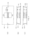
- FIG. 1(a) illustrates a top view of a wireless power transmitting device (secondary transmitting device) including a leakage preventing device according to a first embodiment and a secondary resonator.
- FIG. 1(b) illustrates a front view for the time when a wireless power transmitting device (primary transmitting device) including a primary resonator is made to be opposed to the wireless power transmitting device in FIG 1(a) .
- This leakage preventing device includes a conductor plate 102 and conductive objects 103 and 104.
- the conductive objects 103 and 104 have the form of a conductive wire.
- a secondary resonator 106 includes a magnetic core 106A, and a transmission coil 106B wound around the magnetic core 106A.
- the magnetic core 106A has an approximately flat shape.
- the transmission coil 106B has an approximately flat upper cross section.
- the conductor plate 102 is disposed on the back surface side of the secondary resonator 106, that is, on the opposite side of the side where the secondary resonator 106 is opposed to a primary resonator 105.
- the conductive wire 103 is disposed away from the secondary resonator 106 in a direction parallel to a width direction of the coil 106B.
- One end of the conductive wire 103 is connected to the conductor plate 102, and the other end of the conductive wire 103 is electrically connectable and separable to/from a conductive plate 101 by being brought into contact or non-contact with the surface of the conductive plate 101.
- the other end is curved in a J shape at one end and is to be in contact with the conductive plate 101 at the curve part.
- FIG. 1(b) a connected state is illustrated.
- the conductive wire 104 is disposed away from the secondary resonator 106 in a direction approximately opposite to the conductive wire 103. Between the conductive wires 104 and 103, the secondary resonator 106 is positioned. One end of the conductive wire 104 is connected to the conductor plate 102, and the other end is electrically connectable and separable to/from the conductive plate 101 by being brought into contact or non-contact with the surface of the conductive plate 101. The other end is curved in a J shape at one end and is to be in contact with the conductive plate 101 at the curve part. In FIG. 1(b) , the connected state is illustrated. Also, the other ends of the conductive wires 103 and 104 are in the form of being suspended from the conductive plate 102 on the upper side.
- the conductive wires 103 and 104 While one end of the conductive wires 103 and 104 is fixedly connected to the conductive plate 102 in FIG. 1(b) , however, a connectable and separable configuration may be adapted as well. Also, the conductive wires 103 and 104 may be disposed approximately in parallel to the conductive plate 102 and turned to the state that both ends are released in non-use (when not performing the wireless power transmission) and turned to the form that the other end is suspended from the conductive plate 102 and one end is automatically connected to the conductor plate 102 as in FIG. 1(b) in use.
- the primary resonator 105 includes a magnetic core 105A, and a reception coil 105B wound around the magnetic core 105A.
- the magnetic core 105A has an approximately flat shape.
- the reception coil 105B has an approximately flat upper cross section.
- a conductive loop is formed so as to surround a resonator pair by the conductive wires 103 and 104 and the conductive plates 101 and 102.
- the conductive loop surrounds the entire resonator pair so as to go around the left, right, up and down of the resonator pair along a paper surface of FIG. 1(b) .
- the conductive loop is approximately parallel to a winding direction of the coils 106B and 105B. However, being parallel is not essential. By the conductive loop, the leakage of the electromagnetic waves to the surroundings is reduced during the wireless power transmission from the primary side to the secondary side.
- conductive wires 103A and 104A may be installed to the primary conductor plate 101 as illustrated in FIG. 1(c) .
- one end of the conductive wires 103A and 104A is connected to the conductor plate 101, and the other end is electrically connectable and separable to/from the conductor plate 102.
- the other end of the conductive wires 103A and 104A is electrically connected to the secondary conductive plate 102.
- the state at the time is illustrated in FIG. 1(c) .
- the conductive wires 103A and 104A are in the form of rising from the conductive plate 101 on the lower side. In such a manner, even when the conductive wire is formed on the primary conductive plate, since a conductive loop is formed around the resonator pair, a magnetic shielding is effectively formed, and the leakage of the electromagnetic waves to the surroundings is prevented.
- While one end of the conductive wire 103 is connected to a surface on the side opposed to the conductor plate 102 of the conductor plate 101 in the example illustrated in FIG. 1(b) , the configuration of being connected to a surface on the opposite side is also possible.
- a small hole may be formed on the conductor plate 101, one end of the conductive wire 103 may be made to pass through the hole and one end of a J-shape may be brought into contact with the surface on the opposite side.
- An oblong hole may be formed in accordance with the width of a J shape and the thickness of the wire, and the wire may be made to pass through the hole and then rotated by 90 degrees around an axis or the like so that the wire is prevented from easily getting off.
- the conductive wire 104 may be configured similarly to the conductive wire 103.
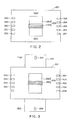
- FIG. 2 illustrates a wireless power transmitting device including a leakage preventing device according to a second embodiment and a resonator.
- the resonator may be either primary resonator or secondary resonator.
- the leakage preventing device includes a conductor plate 201 and a set of a plurality of conductive wires 203 and 204 whose one end is connected to the conductor plate 201. The other end of them is brought into contact with the conductor plate on a back surface of the resonator that is arranged oppositely during power transmission and is electrically connected with the conductor plate.
- a plurality of short-circuit loops are formed at different parts in a longitudinal direction. Therefore, there is a function of canceling the magnetic fluxes for the unbalance at different locations in the longitudinal direction, and a leakage magnetic field to the surroundings can be reduced more.
- FIG. 4(a) illustrates a simulation result by a configuration of the second embodiment. Five loops are disposed at the interval of 10 cm.
- FIG. 4(b) illustrates a simulation result by a configuration (conventional configuration) for which all the conductive wires 203 and 204 are removed from the configuration in FIG. 2 . In the conventional configuration, the conductive loop is not formed.
- the surrounding magnetic field can be reduced greatly.
- the magnetic field in FIG. 4(a) can obtain the reduction effect of about 1/20 of the magnetic field in FIG. 4(b) , that is -26 dB.
- a configuration of disposing a conductive brush and a coil spring densely so as to surround a resonator pair is known. It is forming a sealed space around the resonator pair by respective metal wires configuring the conductive brush and the respective coil springs, and prevents the leakage of the electromagnetic waves. Only when the condition that the respective metal wires and the respective coil springs are brought into electric contact with both metal plates disposed above and below the resonator pair is satisfied, a magnetic shielding effect is generated. In the configuration, the conductive brush and the coil spring have to be densely disposed, causing problems of weight increase and cost increase. Also, in terms of the configuration, a gap from the metal plate tends to be generated.
- FIG. 3 illustrates a wireless power transmitting device including a leakage preventing device according to a third embodiment and a resonator.
- the resonator may be either primary resonator or secondary resonator.
- the same symbols are attached for the parts similar to FIG. 2 and redundant descriptions are omitted.
- the conductive plate 202 is provided on a back surface side (a back side toward the paper surface) of the conductive plate 201.
- the conductive plate 202 may be formed integrally with the conductive plate 201 or may be provided on a front surface side (a front side toward the paper surface) of the conductive plate 201.
- a conductive object 207 is disposed away from the resonator 205.
- a conductive object 208 is disposed away from the resonator 205 in a direction approximately opposite to the conductive object 207.
- One end of the conductive objects 207 and 208 is connected to the conductive plate 202, and the other end of the conductive objects 207 and 208 is brought into contact with the conductor plate on the back surface side of the resonator that is arranged to be opposed to the resonator 205 during the power transmission and is electrically connected with the conductor plate.
- a loop that goes around in a vertical direction (longitudinal direction) along the paper surface is formed. The loop is approximately perpendicular to the five loops formed by the conductor wires 203 and 204.
- the magnetic fluxes in the opposite direction and the longitudinal direction of the pair of the upper and lower resonators are generated.
- the unbalance of the magnetic fluxes in a horizontal direction is generated.
- the loop in the longitudinal direction of this embodiment functions to cancel the unbalance.
- the leakage magnetic field to the surroundings can be reduced.
- FIG. 5 illustrates a wireless power transmitting device including a leakage preventing device according to a fourth embodiment and a resonator.
- the resonator may be either primary resonator or secondary resonator.
- the same symbols are attached for the parts similar to FIG. 3 and redundant descriptions are omitted.
- FIG. 6(a), FIG. 6(b), FIG. 6(c) and FIG. 6(d) a front view of a wireless power transmission system including a leakage preventing device according to a fifth embodiment is illustrated.
- the same symbols are attached to elements corresponding to FIG. 1 and redundant descriptions are omitted.
- a modification of the conductive object in the first embodiment is illustrated in all of FIG. 6(a), FIG. 6(b), FIG. 6(c) and FIG. 6(d) .
- one end of conductive wires 301 and 302 is connected respectively to the conductive plate 101 on the primary side, and a J-shaped hook-like part (hook part) is formed at the other end.
- One end of conductive wires 303 and 304 is also connected respectively to the conductive plate 102 on the secondary side and the J-shaped hook-like part (hook part) is formed at the other end.
- lengths of the conductive wires on the primary side and the secondary side are different from that in FIG. 6(a) .
- the conductive wire connected to the conductive plate 101 on the primary side is shorter than the conductive wire connected to the conductive plate 102 on the secondary side.
- conductive wires 311 and 312 connected to the conductive plate 101 on the primary side are longer than conductive wires 313 and 314 connected to the conductive plate 102 on the secondary side.
- one end of conductive wires 321 and 322 is connected respectively to the conductive plate 101 on the primary side, and a spherical projection is formed at the other end.
- One end of conductive wires 323 and 324 is also connected respectively to the conductive plate 102 on the secondary side, and a semispherical recess to be engaged with the projection is formed at the other end.
- the short-circuit loop is formed.
- FIG. 6(d) a relationship between the recesses and the projections formed at the conductive wires on the primary side and the secondary side is opposite to that in FIG. 6(c) .
- the projection is formed at the other end of the conductive wire connected to the conductive plate 101 on the primary side and the recess is formed at the other end of the conductive wire connected to the conductive plate 102 on the secondary side.
- the recess is formed at the other end of conductive wires 331 and 332 connected to the conductive plate 101 on the primary side
- the projection is formed at the other end of conductive wires 333 and 334 connected to the conductive plate 102 on the secondary side.
- the need of determining the size of the projection to be about the same as an allowable range of displacement in all directions of a structure including the upper and lower resonators is generated.
- the conductor plate 101 or the conductor plate 102 is provided with an area corresponding to the allowable range of the displacement in all directions. Therefore, in the configurations of FIG. 1(b) and FIG. 1(c) , there is an advantage that the configuration such as the size of the conductive wire is not greatly restricted.
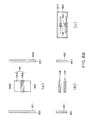
- FIG. 7A(a) and FIG. 7B(a) a top view of a wireless power transmitting device including a leakage preventing device according to a sixth embodiment and a secondary resonator is illustrated.
- a front view of a configuration in which a primary resonator is made to be opposed to the secondary resonator is illustrated in FIG. 7A(b) and FIG. 7B(b)
- a side view of the configuration is illustrated in FIG. 7A(c) and FIG. 7B(c) .
- FIGS. 7A(a)-(c) illustrate a state in non-use of this leakage preventing device
- FIGS. 7B(a)-(c) illustrate a state in use of this leakage preventing device.
- the secondary resonator and the leakage preventing device are disposed at the lower part of a vehicle or the like and the primary resonator is disposed on a parking surface will be assumed and described.
- a short-circuit loop is formed of a set of conductive wires and upper and lower conductive plates in the embodiments so far, in this embodiment, a conductive loop itself is disposed at a position away from a resonator pair. Thus, magnetic fluxes leaking from a certain specific position among positions surrounding the resonator pair can be canceled.
- this embodiment details of this embodiment will be described.
- a conductor loop 701 is disposed away from the resonator 106 in a direction parallel to the width direction of the coil 106B of the secondary resonator 106.
- the conductor loop 701 is formed on a surface of a support 711.
- the support 711 may be constituted of a dielectric for instance.
- a conductor loop 721 is disposed away from the resonator 106 in a direction approximately opposite to the conductor loop 701.
- the conductor loop 721 is formed on a surface of a support 712.
- the support 712 may be constituted of a dielectric for instance.
- the supports 711 and 712 have an approximately flat shape. Postures of the supports 711 and 712 are controllable. As indicated by broken lines in FIG. 7A(b) , the postures are changeable so that loop surfaces of the conductor loops 701 and 702 is opposed to the resonator pair or a space between the resonators.
- the loop surface is a surface that coincides with an area on the inner side of the loop including the conductor loop.
- the loops 701 and 702 and the supports 711 and 712 are housed in a form of being along the lower part of a vehicle or the like, and the loop surface and the surface of the magnetic core 106A are approximately parallel ( FIG. 7A ).
- the conductor loops 701 and 702 and the supports 711 and 712 thereof are suspended approximately vertically from a state of being approximately parallel to the surface of the magnetic core 106A.
- the conductor loops 701 and 702 and the supports 711 and 712 are disposed in a space between the lower part of the vehicle or the like and the parking surface, and the loop surfaces of the conductor loops 701 and 702 is perpendicular to the width direction of the coils of the respective resonators.
- an induced current corresponding to the magnetic fluxes passing through the loops 701 and 702 flows in the loop so that the leakage of the magnetic fluxes to the outside from between the lower part of the vehicle and the parking surface can be reduced.
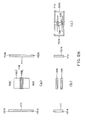
- FIG. 8A(a) and FIG. 8B(a) a top view of a wireless power transmitting device including a leakage preventing device according to a seventh embodiment and a primary resonator is illustrated.
- a front view of a configuration in which a secondary resonator is made to be opposed to the primary resonator is illustrated in FIG. 8A(b) and FIG. 8B(b)
- a side view of the configuration is illustrated in FIG. 8A(c) and FIG. 8B(c) .
- FIGS. 8A(a)-(c) illustrate a state in non-use of this leakage preventing device
- FIGS. 8B(a)-(c) illustrate a state in use of this leakage preventing device.
- conductive loop and the support are disposed on the secondary side (vehicle or the like) in the sixth embodiment, in this embodiment, conductive loops 801 and 802 and supports 811 and 812 thereof are disposed on the primary (parking surface or the like). Otherwise, it is similar to the sixth embodiment.
- the loop surfaces of the loops 801 and 802 are approximately parallel to the surface of the magnetic core 105A.
- the loops 801 and 802 and the supports 811 and 812 are housed in the form of being along the parking surface.
- the conductive loops 801 and 802 and the supports 811 and 812 thereof are erected approximately vertically from a state of being parallel to the surface of the magnetic core 105A, and the respective loop surfaces of the conductor loops 801 and 802 is perpendicular to the width direction of the coil.
- the wireless power transmission is performed from the primary resonator 105 to the secondary resonator 106 in the state, the induced current corresponding to the magnetic fluxes passing through the loops 801 and 802 flows in the loops so that the magnetic fluxes leaking to the outside can be reduced.
- FIG. 9A(a) and FIG. 9B(a) a top view of a wireless power transmitting device including a leakage preventing device according to an eighth embodiment and a secondary resonator is illustrated.
- a front view of a configuration in which a primary resonator is made to be opposed to the secondary resonator is illustrated in FIG. 9A(b) and FIG. 9B(b)
- a side view of the configuration is illustrated in FIG. 9A(c) and FIG. 9B(c) .
- FIGS. 9A(a)-(c) illustrate a state in non-use of this leakage preventing device
- FIGS. 9B(a)-(c) illustrate a state in use of this leakage preventing device.
- the secondary resonator and the leakage preventing device are disposed at the lower part of a vehicle or the like and the primary resonator is disposed on a parking surface will be assumed and described.
- a plurality of conductor loops are disposed to the single support.
- the plurality of conductor loops 701A and 701B are disposed to the single support 711.
- the plurality of conductor loops 701A and 701B are disposed along a direction parallel to the length direction of the coil.
- the plurality of conductor loops 711A and 711B are disposed to the single support 712.
- the conductor loops 711A and 711B are disposed along the direction parallel to the length direction of the coil.
- the magnetic fluxes that cross the loops are reduced, and the induced current is reduced.
- the flowing induced current becomes too big by the single loop and there is the need of increasing the thickness and conductivity of a conductor configuring the loop.
- the limitation can be mitigated.
- the magnetic fluxes passing through the gap cannot be captured. Therefore, there is the case that a better effect can be obtained in the sixth embodiment.
- the leakage preventing device is disposed on the secondary side in this embodiment, the configuration of disposing it on the primary similarly to the seventh embodiment illustrated in FIG. 8A and FIG. 8B is also possible.
- FIG. 10 illustrates a wireless power transmission system including a leakage preventing device according to a ninth embodiment.
- a vehicle body of a car or the like is constituted of a conductor
- the conductor of the vehicle body a metal plate (conductor plate) laid in a parking space, and two conductive wires are used to configure a short-circuit loop.
- a primary resonator is disposed on a parking surface
- a secondary resonator is disposed at the lower part of the vehicle body so as to be opposed to the primary resonator.
- FIG. 10(a) illustrates a state in non-use of the leakage preventing device
- FIG. 10(b) illustrates a state in use of an electromagnetic wave leakage prevention function.
- conductive wires 801 and 802 at two parts to be used for forming the short-circuit loop are housed at the lower part of a vehicle body 804.
- one ends of the conductive wires 801 and 802 at two parts are lowered to a metal plate 803 laid in the parking space and connected to the metal plate 803.
- the conductive wires 801 and 802 the metal plate 803 and the conductor of the vehicle body, the short-circuit loop is formed so as to surround the periphery of the resonator pair.
- the induced current according to the magnetic fluxes passing through the short-circuit loop flows, the leakage of the magnetic fluxes to the outside can be reduced.
- the short-circuit loop is formed utilizing the conductor of the vehicle body in this embodiment, the configuration of separately disposing a metal plate on a lower surface of the vehicle body and utilizing it is also possible.
- the configuration of disposing the conductive wire along the parking surface, springing up (or rising up) one end from below and connecting it to the conductor of the vehicle body as in the first embodiment illustrated in FIG. 1(b) is also possible.
- the configuration of installing the conductive wires to both of the vehicle body and the metal plate of the parking surface and connecting the one ends of both (the recess and the projection with each other, or the hook parts with each other) is also possible.
- FIG. 11 illustrates a wireless power transmission system including a leakage preventing device according to a tenth embodiment.
- a vehicle body of a train or the like is constituted of a conductor and a wheel can be considered as a conductor in the view from transmission signals further (for instance, when a surface of the wheel is the conductor), the rail of the train, the wheel and conductive wires at two parts are used to configure a short-circuit loop.
- the primary resonator is disposed at the rail, and the secondary resonator is disposed at the lower part of the vehicle body of the train so as to be opposed to the primary resonator.
- the vehicle can be an automobile or the like, not the train, as long as a conductor is formed in a circulating shape on the surface of a wheel, and in this case, a metal plate disposed on a parking surface may be used instead of the rail.
- FIG. 11(a) illustrates a state in non-use of the leakage preventing device
- FIG. 11(b) illustrates a state in use of the leakage preventing device.
- conductive wires 901 and 902 at two parts to be used for forming the short-circuit loop are housed at the lower part of a vehicle body 907.
- one ends of the conductive wires 901 and 902 at two parts are lowered to wheels 904 and 905 and electrically connected to the surface of the wheels 904 and 905.
- the short-circuit loop is formed so as to surround the periphery of the resonator pair.
- the induced current according to the magnetic fluxes passing through the short-circuit loop flows, the leakage of the magnetic fluxes to the outside can be reduced.
- a conductive shaft connecting conductive wheels with each other may be used instead of the rail to form the short-circuit loop.
- the wheels to be utilized for forming the short-circuit loop may not be front and rear wheels of the train but may be left and right wheels.
- a monitor which monitors the induced current flowing in the short-circuit loop can be provided.
- the monitor value becomes large. Then, by performing displacement correcting work while observing the monitor value, confirming that the monitor value has lowered, and ending the correction of the displacement, power efficiency can be improved more.
- a cancellation current generator may be added to the short-circuit loop, and an additional current may be impressed further in addition to the induced current when the monitor value is large.
- an additional current may be impressed further in addition to the induced current when the monitor value is large.
- the induced current flows in the conductive objects and the conductor plates forming the short-circuit loop. Therefore, depending on a flowing current amount, there is the possibility of causing an electric shock or the like by a human body or the like being brought into contact when exposed. In order to prevent that, covering parts other than the part with the possibility of being in mutual contact with the conductive objects or the conductor plates with an insulator of a resin or rubber or the like may be taken into consideration.
- FIG. 12 illustrates a wireless power transmission system including the leakage preventing device according to an eleventh embodiment.
- FIG. 12(a) illustrates a state in non-use of the leakage preventing device
- FIG. 12(b) illustrates a state in use of the leakage preventing device.
- Drawings on the upper side of FIG. 12(a) and FIG. 12(b) are top views and drawings on the lower side are side views.
- Horizontally wound primary resonance coil 1204 and secondary 1205 are oppositely disposed.
- a conductive plate 1202 is disposed on the back surface side of the primary resonance coil 1204, and a conductive plate 1203 is disposed on the back surface side of the secondary resonance coil 1205.
- a magnetic material block 1201 is disposed on the primary side.
- the magnetic material block 1201 has a columnar shape. On the conductor plate 1202 on the primary side, a hole that the magnetic material block 1201 passes through is formed. The hole of the conductor plate 1202 and a through-hole of the primary resonance coil 1204 are positioned, and the magnetic material block 1201 is capable of passing through the hole of the conductor plate 1202 and moving inside the primary resonance coil 1204. Further, when the secondary resonance coil 1205 is disposed to be opposed to the primary resonance coil 1204, the magnetic material block 1201 can be inserted also to the inside of the secondary resonance coil 1205. The magnetic material block 1201 may be moved by a mechanical, magnetic or electrical method. This leakage preventing device may include a moving unit for the magnetic material block 1201.
- a large part of the magnetic material block 1201 is housed at the lower part of a parking surface, and a part passes through the primary resonance coil 1204 and enters a space between the resonators 1204 and 1205.
- the magnetic material block 1201 is elevated so as to pass through the inside of the lower resonance coil 1204, the space between the resonators 1204 and 1205, and the inside of the resonance coil 1205, and the one end is brought into contact with the conductive plate 1203.
- the magnetic material block 1201 is elevated in such a manner, by transmitting power from the primary side to the secondary side, a large part of the magnetic fluxes flows in the magnetic material block 1201.
- the effective magnetic shielding is made possible.
- the effects of improving a coupling coefficient between the upper and lower resonators 1204 and 1205 and also improving power transmission efficiency are generated.
- the leakage of the electromagnetic waves in the vertical direction of the resonator pair is prevented by the conductive plates 1203 and 1202 as well.
- the magnetic material block does not always need to be present inside the upper and lower coils during the time of use, and when it is present in at least a part of the space between the upper and lower coils at least, the effect of preventing the electromagnetic wave leakage can be obtained. For instance, in the case that a cover is put on the resonator coil on the secondary side attached to the vehicle side or the like, even when the magnetic material block does not reach the inside of the coil inside the cover, it is sufficient when the magnetic material block is elevated to the surface of the cover or the vicinity thereof. Since a large part of the magnetic fluxes intensively flows in the magnetic material block to the upper end of the magnetic material block, a magnetic shielding effect is generated. Also, the magnetic material block may be shortened such that the magnetic material block is not present inside the upper and lower coils and the magnetic material block is present only in the space between the upper and lower coils.
- the magnetic material block is moved so as to increase an area occupied in the space between the resonators during the time of use rather than during the time of non-use.
- the magnetic material block is prevented from significantly projecting from the parking surface and getting broken during the time of non-use, and it is projected from the parking surface to dispose more part in the space between the resonators during the time of use, thereby sufficiently demonstrating a magnetic shielding function.
- the magnetic material block is disposed on the primary side in the above-described example, it may be disposed on the secondary side. Or, the magnetic material block may be disposed on both of the primary side and the secondary side, and in this case, during the time of use, both magnetic material blocks are moved inside the coil on the primary side and the coil on the secondary side and sent out to the space between the coils.
Landscapes
- Engineering & Computer Science (AREA)
- Power Engineering (AREA)
- Computer Networks & Wireless Communication (AREA)
- Physics & Mathematics (AREA)
- Electromagnetism (AREA)
- Electric Propulsion And Braking For Vehicles (AREA)
- Near-Field Transmission Systems (AREA)
- Shielding Devices Or Components To Electric Or Magnetic Fields (AREA)
Applications Claiming Priority (1)
| Application Number | Priority Date | Filing Date | Title |
|---|---|---|---|
| JP2013122831A JP2014241673A (ja) | 2013-06-11 | 2013-06-11 | 電磁波漏洩防止装置 |
Publications (2)
| Publication Number | Publication Date |
|---|---|
| EP2814046A2 true EP2814046A2 (de) | 2014-12-17 |
| EP2814046A3 EP2814046A3 (de) | 2015-04-29 |
Family
ID=50771183
Family Applications (1)
| Application Number | Title | Priority Date | Filing Date |
|---|---|---|---|
| EP20140169629 Withdrawn EP2814046A3 (de) | 2013-06-11 | 2014-05-23 | Vorrichtung zum Verhindern von Lecks elektromagnetischer Wellen |
Country Status (4)
| Country | Link |
|---|---|
| US (1) | US20140361632A1 (de) |
| EP (1) | EP2814046A3 (de) |
| JP (1) | JP2014241673A (de) |
| CN (1) | CN104242480A (de) |
Cited By (4)
| Publication number | Priority date | Publication date | Assignee | Title |
|---|---|---|---|---|
| WO2018057346A1 (en) * | 2016-09-23 | 2018-03-29 | Apple Inc. | Electromagnetic shielding for wireless power transfer systems |
| US10084349B2 (en) | 2017-02-15 | 2018-09-25 | Apple Inc. | Inductive module |
| US10910862B2 (en) | 2016-09-23 | 2021-02-02 | Apple Inc. | Electromagnetic shielding for wireless power transfer systems |
| WO2024035704A1 (en) * | 2022-08-09 | 2024-02-15 | Apple Inc. | Wireless power transfer structure |
Families Citing this family (4)
| Publication number | Priority date | Publication date | Assignee | Title |
|---|---|---|---|---|
| JP2014165997A (ja) | 2013-02-22 | 2014-09-08 | Toshiba Corp | 電磁波漏洩防止装置および無線電力伝送システム |
| US10391871B2 (en) * | 2014-01-10 | 2019-08-27 | Witricity Corporation | Controlling current flow path in wireless electric vehicle charging systems for mitigating RF radiated emissions |
| WO2016136568A1 (ja) * | 2015-02-25 | 2016-09-01 | 株式会社村田製作所 | 回路装置および電力伝送システム |
| US11936196B2 (en) * | 2020-04-16 | 2024-03-19 | Inductev Inc. | Failsafe safety circuits for protection from faults or loss of rectification control during wireless power transfer |
Family Cites Families (13)
| Publication number | Priority date | Publication date | Assignee | Title |
|---|---|---|---|---|
| JPH04348508A (ja) * | 1991-05-27 | 1992-12-03 | Toshiba Corp | 静止誘導電気機器 |
| CN100562242C (zh) * | 2006-12-21 | 2009-11-18 | 西北工业大学 | 一种可用于微波炉和电脑的负磁导率材料电磁屏蔽装置 |
| JP4743244B2 (ja) * | 2008-09-18 | 2011-08-10 | トヨタ自動車株式会社 | 非接触受電装置 |
| JP5710209B2 (ja) * | 2010-01-18 | 2015-04-30 | 東京エレクトロン株式会社 | 電磁波給電機構およびマイクロ波導入機構 |
| JP2013534041A (ja) * | 2010-05-26 | 2013-08-29 | エー ビー ビー リサーチ リミテッド | 電力を受信するためのワイヤレス電力受信ユニット、電力を伝達するためのワイヤレス電力伝達ユニット、ワイヤレス電力送信デバイス、およびワイヤレス電力送信デバイスの使用 |
| JP5759716B2 (ja) * | 2010-12-22 | 2015-08-05 | 富士通テン株式会社 | 無線電力伝送システム |
| JP5740200B2 (ja) * | 2011-04-22 | 2015-06-24 | 矢崎総業株式会社 | 共鳴式非接触給電システム、受電側装置及び送電側装置 |
| US10230268B2 (en) * | 2011-09-26 | 2019-03-12 | Korea Advanced Institute Of Science And Technology | Power supply and pickup system capable of maintaining stability of transmission efficiency despite changes in resonant frequency |
| JP2015008548A (ja) * | 2011-10-28 | 2015-01-15 | パナソニック株式会社 | 非接触電力伝送装置 |
| CN103975400B (zh) * | 2011-11-18 | 2017-07-11 | 丰田自动车株式会社 | 输电装置、受电装置及电力传输系统 |
| JP5810944B2 (ja) * | 2012-01-31 | 2015-11-11 | トヨタ自動車株式会社 | 車両および電力伝送システム |
| JP5938288B2 (ja) * | 2012-07-19 | 2016-06-22 | 株式会社日立パワーソリューションズ | 無線給電装置 |
| JP6148501B2 (ja) * | 2013-03-01 | 2017-06-14 | 株式会社東芝 | 送電システム |
-
2013
- 2013-06-11 JP JP2013122831A patent/JP2014241673A/ja active Pending
-
2014
- 2014-05-23 EP EP20140169629 patent/EP2814046A3/de not_active Withdrawn
- 2014-06-09 US US14/299,528 patent/US20140361632A1/en not_active Abandoned
- 2014-06-10 CN CN201410254225.XA patent/CN104242480A/zh active Pending
Non-Patent Citations (1)
| Title |
|---|
| None |
Cited By (6)
| Publication number | Priority date | Publication date | Assignee | Title |
|---|---|---|---|---|
| WO2018057346A1 (en) * | 2016-09-23 | 2018-03-29 | Apple Inc. | Electromagnetic shielding for wireless power transfer systems |
| US10910862B2 (en) | 2016-09-23 | 2021-02-02 | Apple Inc. | Electromagnetic shielding for wireless power transfer systems |
| EP3411889B1 (de) * | 2016-09-23 | 2024-12-11 | Apple Inc. | Elektromagnetische abschirmung für systeme zum drahtlosen stromtransfer |
| US10084349B2 (en) | 2017-02-15 | 2018-09-25 | Apple Inc. | Inductive module |
| WO2024035704A1 (en) * | 2022-08-09 | 2024-02-15 | Apple Inc. | Wireless power transfer structure |
| US12249839B2 (en) | 2022-08-09 | 2025-03-11 | Apple Inc. | Wireless power transfer structure |
Also Published As
| Publication number | Publication date |
|---|---|
| US20140361632A1 (en) | 2014-12-11 |
| EP2814046A3 (de) | 2015-04-29 |
| JP2014241673A (ja) | 2014-12-25 |
| CN104242480A (zh) | 2014-12-24 |
Similar Documents
| Publication | Publication Date | Title |
|---|---|---|
| EP2814046A2 (de) | Vorrichtung zum Verhindern von Lecks elektromagnetischer Wellen | |
| US9859718B2 (en) | Power supply unit, power receiving unit, and power supply system | |
| US9793045B2 (en) | Contactless power transfer transformer for moving body | |
| JP6230776B2 (ja) | 誘導電力伝達装置 | |
| US20160355094A1 (en) | Power receiving system | |
| EP2841293B1 (de) | Bereitstellung eines landfahrzeuges, insbesondere eines schienenfahrzeuges oder strassenfahrzeuges, mit elektrischer energie durch induktion | |
| KR101364185B1 (ko) | 루프형태의 전자파 차폐장치 | |
| JP2011045189A (ja) | 無線電力伝送システムにおける電磁波遮蔽方法および装置並びに無線電力送電装置 | |
| CN103490526B (zh) | 用于感应地无线输出能量的装置 | |
| JP2017168522A (ja) | コイル装置 | |
| US20190326049A1 (en) | Coil device and holder | |
| JP6086189B2 (ja) | コイル装置 | |
| JP2012228149A (ja) | 共鳴式非接触給電システム | |
| US20150380154A1 (en) | Power supplying side coil and contactless power supplying apparatus | |
| KR101087768B1 (ko) | 자기유도 전력전달용 급전장치와 집전장치의 전자기 차폐장치 | |
| WO2019176637A1 (ja) | アンテナ装置、通信システム、及び電子機器 | |
| JP2014179438A (ja) | コイルユニット及び非接触給電装置 | |
| Kim et al. | Electromagnetic interference and radiation from wireless power transfer systems | |
| JP2020167753A (ja) | 送電装置、受電装置および非接触給電システム | |
| JP6232191B2 (ja) | 給電部、受電部及び給電システム | |
| JP2024510294A (ja) | モジュール式磁束制御 | |
| EP3487036B1 (de) | Vorrichtung zur drahtlosen stromübertragung und system zur drahtlosen stromübertragung | |
| KR101853491B1 (ko) | 무선전력전송 코일 구조체 및 무선전력전송 시스템 | |
| JP2014171292A (ja) | 送電システム | |
| KR102041988B1 (ko) | 무선 전력 전송 장치 |
Legal Events
| Date | Code | Title | Description |
|---|---|---|---|
| 17P | Request for examination filed |
Effective date: 20140523 |
|
| AK | Designated contracting states |
Kind code of ref document: A2 Designated state(s): AL AT BE BG CH CY CZ DE DK EE ES FI FR GB GR HR HU IE IS IT LI LT LU LV MC MK MT NL NO PL PT RO RS SE SI SK SM TR |
|
| AX | Request for extension of the european patent |
Extension state: BA ME |
|
| PUAI | Public reference made under article 153(3) epc to a published international application that has entered the european phase |
Free format text: ORIGINAL CODE: 0009012 |
|
| RIC1 | Information provided on ipc code assigned before grant |
Ipc: H01F 27/36 20060101AFI20141127BHEP Ipc: H01F 38/14 20060101ALI20141127BHEP Ipc: H02J 7/02 20060101ALI20141127BHEP |
|
| PUAL | Search report despatched |
Free format text: ORIGINAL CODE: 0009013 |
|
| AK | Designated contracting states |
Kind code of ref document: A3 Designated state(s): AL AT BE BG CH CY CZ DE DK EE ES FI FR GB GR HR HU IE IS IT LI LT LU LV MC MK MT NL NO PL PT RO RS SE SI SK SM TR |
|
| AX | Request for extension of the european patent |
Extension state: BA ME |
|
| RIC1 | Information provided on ipc code assigned before grant |
Ipc: H01F 27/36 20060101AFI20150325BHEP Ipc: H01F 38/14 20060101ALI20150325BHEP Ipc: H02J 7/02 20060101ALI20150325BHEP |
|
| 17Q | First examination report despatched |
Effective date: 20160801 |
|
| STAA | Information on the status of an ep patent application or granted ep patent |
Free format text: STATUS: EXAMINATION IS IN PROGRESS |
|
| STAA | Information on the status of an ep patent application or granted ep patent |
Free format text: STATUS: THE APPLICATION IS DEEMED TO BE WITHDRAWN |
|
| 18D | Application deemed to be withdrawn |
Effective date: 20161012 |