EP2814084A1 - Batterie secondaire - Google Patents
Batterie secondaire Download PDFInfo
- Publication number
- EP2814084A1 EP2814084A1 EP13003238.6A EP13003238A EP2814084A1 EP 2814084 A1 EP2814084 A1 EP 2814084A1 EP 13003238 A EP13003238 A EP 13003238A EP 2814084 A1 EP2814084 A1 EP 2814084A1
- Authority
- EP
- European Patent Office
- Prior art keywords
- electrode
- battery
- secondary battery
- negative electrode
- lithium
- Prior art date
- Legal status (The legal status is an assumption and is not a legal conclusion. Google has not performed a legal analysis and makes no representation as to the accuracy of the status listed.)
- Withdrawn
Links
- 238000002955 isolation Methods 0.000 claims abstract description 44
- 230000005540 biological transmission Effects 0.000 claims abstract description 42
- 239000000463 material Substances 0.000 claims abstract description 32
- 239000004065 semiconductor Substances 0.000 claims abstract description 27
- 229910052744 lithium Inorganic materials 0.000 claims description 34
- OKTJSMMVPCPJKN-UHFFFAOYSA-N Carbon Chemical compound [C] OKTJSMMVPCPJKN-UHFFFAOYSA-N 0.000 claims description 21
- 239000000126 substance Substances 0.000 claims description 20
- 239000011230 binding agent Substances 0.000 claims description 16
- XUIMIQQOPSSXEZ-UHFFFAOYSA-N Silicon Chemical compound [Si] XUIMIQQOPSSXEZ-UHFFFAOYSA-N 0.000 claims description 15
- 229910021389 graphene Inorganic materials 0.000 claims description 15
- 229910052710 silicon Inorganic materials 0.000 claims description 15
- 239000010703 silicon Substances 0.000 claims description 15
- RYGMFSIKBFXOCR-UHFFFAOYSA-N Copper Chemical compound [Cu] RYGMFSIKBFXOCR-UHFFFAOYSA-N 0.000 claims description 14
- HBBGRARXTFLTSG-UHFFFAOYSA-N Lithium ion Chemical compound [Li+] HBBGRARXTFLTSG-UHFFFAOYSA-N 0.000 claims description 14
- 239000010949 copper Substances 0.000 claims description 14
- 229910052802 copper Inorganic materials 0.000 claims description 13
- PNEYBMLMFCGWSK-UHFFFAOYSA-N Alumina Chemical compound [O-2].[O-2].[O-2].[Al+3].[Al+3] PNEYBMLMFCGWSK-UHFFFAOYSA-N 0.000 claims description 6
- 229920005822 acrylic binder Polymers 0.000 claims description 4
- 229910001392 phosphorus oxide Inorganic materials 0.000 claims description 2
- VSAISIQCTGDGPU-UHFFFAOYSA-N tetraphosphorus hexaoxide Chemical compound O1P(O2)OP3OP1OP2O3 VSAISIQCTGDGPU-UHFFFAOYSA-N 0.000 claims description 2
- 239000010410 layer Substances 0.000 description 56
- 150000002500 ions Chemical class 0.000 description 46
- 239000002131 composite material Substances 0.000 description 43
- WHXSMMKQMYFTQS-UHFFFAOYSA-N Lithium Chemical compound [Li] WHXSMMKQMYFTQS-UHFFFAOYSA-N 0.000 description 28
- 239000002245 particle Substances 0.000 description 24
- 230000000052 comparative effect Effects 0.000 description 19
- 239000003792 electrolyte Substances 0.000 description 19
- 239000011248 coating agent Substances 0.000 description 18
- 238000000576 coating method Methods 0.000 description 18
- 239000011883 electrode binding agent Substances 0.000 description 18
- 238000004519 manufacturing process Methods 0.000 description 15
- 239000007787 solid Substances 0.000 description 14
- 229920001971 elastomer Polymers 0.000 description 13
- 239000005060 rubber Substances 0.000 description 13
- 229910001416 lithium ion Inorganic materials 0.000 description 12
- 239000011149 active material Substances 0.000 description 11
- 238000011156 evaluation Methods 0.000 description 11
- 229910002102 lithium manganese oxide Inorganic materials 0.000 description 11
- VLXXBCXTUVRROQ-UHFFFAOYSA-N lithium;oxido-oxo-(oxomanganiooxy)manganese Chemical group [Li+].[O-][Mn](=O)O[Mn]=O VLXXBCXTUVRROQ-UHFFFAOYSA-N 0.000 description 11
- 229920002521 macromolecule Polymers 0.000 description 11
- 229910052751 metal Inorganic materials 0.000 description 11
- 239000002184 metal Substances 0.000 description 11
- 238000013021 overheating Methods 0.000 description 10
- SECXISVLQFMRJM-UHFFFAOYSA-N N-Methylpyrrolidone Chemical compound CN1CCCC1=O SECXISVLQFMRJM-UHFFFAOYSA-N 0.000 description 9
- VYPSYNLAJGMNEJ-UHFFFAOYSA-N Silicium dioxide Chemical compound O=[Si]=O VYPSYNLAJGMNEJ-UHFFFAOYSA-N 0.000 description 9
- 239000007771 core particle Substances 0.000 description 9
- 239000006104 solid solution Substances 0.000 description 9
- 238000002156 mixing Methods 0.000 description 8
- 238000009782 nail-penetration test Methods 0.000 description 8
- KMTRUDSVKNLOMY-UHFFFAOYSA-N Ethylene carbonate Chemical compound O=C1OCCO1 KMTRUDSVKNLOMY-UHFFFAOYSA-N 0.000 description 7
- NIXOWILDQLNWCW-UHFFFAOYSA-N acrylic acid group Chemical group C(C=C)(=O)O NIXOWILDQLNWCW-UHFFFAOYSA-N 0.000 description 7
- -1 lithium transition metal Chemical class 0.000 description 7
- 239000002105 nanoparticle Substances 0.000 description 7
- 229910052814 silicon oxide Inorganic materials 0.000 description 7
- 229920000178 Acrylic resin Polymers 0.000 description 6
- 239000004925 Acrylic resin Substances 0.000 description 6
- KRHYYFGTRYWZRS-UHFFFAOYSA-N Fluorane Chemical compound F KRHYYFGTRYWZRS-UHFFFAOYSA-N 0.000 description 6
- 229910052787 antimony Inorganic materials 0.000 description 6
- WATWJIUSRGPENY-UHFFFAOYSA-N antimony atom Chemical compound [Sb] WATWJIUSRGPENY-UHFFFAOYSA-N 0.000 description 6
- 239000000919 ceramic Substances 0.000 description 6
- JBTWLSYIZRCDFO-UHFFFAOYSA-N ethyl methyl carbonate Chemical compound CCOC(=O)OC JBTWLSYIZRCDFO-UHFFFAOYSA-N 0.000 description 6
- 239000000203 mixture Substances 0.000 description 6
- 238000009783 overcharge test Methods 0.000 description 6
- 229920002134 Carboxymethyl cellulose Polymers 0.000 description 5
- OAICVXFJPJFONN-UHFFFAOYSA-N Phosphorus Chemical compound [P] OAICVXFJPJFONN-UHFFFAOYSA-N 0.000 description 5
- 229910052783 alkali metal Inorganic materials 0.000 description 5
- 150000001340 alkali metals Chemical class 0.000 description 5
- 229910052784 alkaline earth metal Inorganic materials 0.000 description 5
- 229910052782 aluminium Inorganic materials 0.000 description 5
- XAGFODPZIPBFFR-UHFFFAOYSA-N aluminium Chemical compound [Al] XAGFODPZIPBFFR-UHFFFAOYSA-N 0.000 description 5
- 239000007773 negative electrode material Substances 0.000 description 5
- 239000010450 olivine Substances 0.000 description 5
- 229910052609 olivine Inorganic materials 0.000 description 5
- 230000035515 penetration Effects 0.000 description 5
- 229910052698 phosphorus Inorganic materials 0.000 description 5
- 239000011574 phosphorus Substances 0.000 description 5
- 238000010248 power generation Methods 0.000 description 5
- VAYTZRYEBVHVLE-UHFFFAOYSA-N 1,3-dioxol-2-one Chemical compound O=C1OC=CO1 VAYTZRYEBVHVLE-UHFFFAOYSA-N 0.000 description 4
- 230000005355 Hall effect Effects 0.000 description 4
- 229910014553 LixNiyMz Inorganic materials 0.000 description 4
- 239000002033 PVDF binder Substances 0.000 description 4
- 229920002125 Sokalan® Polymers 0.000 description 4
- QVGXLLKOCUKJST-UHFFFAOYSA-N atomic oxygen Chemical compound [O] QVGXLLKOCUKJST-UHFFFAOYSA-N 0.000 description 4
- 239000011888 foil Substances 0.000 description 4
- 229910052736 halogen Inorganic materials 0.000 description 4
- 150000002367 halogens Chemical class 0.000 description 4
- 230000007246 mechanism Effects 0.000 description 4
- 238000002844 melting Methods 0.000 description 4
- 230000008018 melting Effects 0.000 description 4
- 229910052760 oxygen Inorganic materials 0.000 description 4
- 239000001301 oxygen Substances 0.000 description 4
- 239000004584 polyacrylic acid Substances 0.000 description 4
- 229920002239 polyacrylonitrile Polymers 0.000 description 4
- 229920002981 polyvinylidene fluoride Polymers 0.000 description 4
- 239000007774 positive electrode material Substances 0.000 description 4
- 229910000668 LiMnPO4 Inorganic materials 0.000 description 3
- 229910013716 LiNi Inorganic materials 0.000 description 3
- 229910001290 LiPF6 Inorganic materials 0.000 description 3
- PXHVJJICTQNCMI-UHFFFAOYSA-N Nickel Chemical compound [Ni] PXHVJJICTQNCMI-UHFFFAOYSA-N 0.000 description 3
- 239000006230 acetylene black Substances 0.000 description 3
- 235000010948 carboxy methyl cellulose Nutrition 0.000 description 3
- 239000001768 carboxy methyl cellulose Substances 0.000 description 3
- 239000008112 carboxymethyl-cellulose Substances 0.000 description 3
- 150000001768 cations Chemical class 0.000 description 3
- 229910010293 ceramic material Inorganic materials 0.000 description 3
- 239000004020 conductor Substances 0.000 description 3
- IEJIGPNLZYLLBP-UHFFFAOYSA-N dimethyl carbonate Chemical compound COC(=O)OC IEJIGPNLZYLLBP-UHFFFAOYSA-N 0.000 description 3
- 239000011521 glass Substances 0.000 description 3
- 230000020169 heat generation Effects 0.000 description 3
- XEEYBQQBJWHFJM-UHFFFAOYSA-N iron Substances [Fe] XEEYBQQBJWHFJM-UHFFFAOYSA-N 0.000 description 3
- QSZMZKBZAYQGRS-UHFFFAOYSA-N lithium;bis(trifluoromethylsulfonyl)azanide Chemical compound [Li+].FC(F)(F)S(=O)(=O)[N-]S(=O)(=O)C(F)(F)F QSZMZKBZAYQGRS-UHFFFAOYSA-N 0.000 description 3
- 239000012046 mixed solvent Substances 0.000 description 3
- 239000000178 monomer Substances 0.000 description 3
- 239000011369 resultant mixture Substances 0.000 description 3
- 239000010935 stainless steel Substances 0.000 description 3
- 229910001220 stainless steel Inorganic materials 0.000 description 3
- 229910052723 transition metal Inorganic materials 0.000 description 3
- FSSPGSAQUIYDCN-UHFFFAOYSA-N 1,3-Propane sultone Chemical compound O=S1(=O)CCCO1 FSSPGSAQUIYDCN-UHFFFAOYSA-N 0.000 description 2
- SJHAYVFVKRXMKG-UHFFFAOYSA-N 4-methyl-1,3,2-dioxathiolane 2-oxide Chemical compound CC1COS(=O)O1 SJHAYVFVKRXMKG-UHFFFAOYSA-N 0.000 description 2
- NLHHRLWOUZZQLW-UHFFFAOYSA-N Acrylonitrile Chemical compound C=CC#N NLHHRLWOUZZQLW-UHFFFAOYSA-N 0.000 description 2
- OIFBSDVPJOWBCH-UHFFFAOYSA-N Diethyl carbonate Chemical compound CCOC(=O)OCC OIFBSDVPJOWBCH-UHFFFAOYSA-N 0.000 description 2
- PXGOKWXKJXAPGV-UHFFFAOYSA-N Fluorine Chemical compound FF PXGOKWXKJXAPGV-UHFFFAOYSA-N 0.000 description 2
- GYHNNYVSQQEPJS-UHFFFAOYSA-N Gallium Chemical compound [Ga] GYHNNYVSQQEPJS-UHFFFAOYSA-N 0.000 description 2
- DGAQECJNVWCQMB-PUAWFVPOSA-M Ilexoside XXIX Chemical compound C[C@@H]1CC[C@@]2(CC[C@@]3(C(=CC[C@H]4[C@]3(CC[C@@H]5[C@@]4(CC[C@@H](C5(C)C)OS(=O)(=O)[O-])C)C)[C@@H]2[C@]1(C)O)C)C(=O)O[C@H]6[C@@H]([C@H]([C@@H]([C@H](O6)CO)O)O)O.[Na+] DGAQECJNVWCQMB-PUAWFVPOSA-M 0.000 description 2
- FYYHWMGAXLPEAU-UHFFFAOYSA-N Magnesium Chemical compound [Mg] FYYHWMGAXLPEAU-UHFFFAOYSA-N 0.000 description 2
- 229910000831 Steel Inorganic materials 0.000 description 2
- 230000005856 abnormality Effects 0.000 description 2
- 229910001413 alkali metal ion Inorganic materials 0.000 description 2
- 230000015572 biosynthetic process Effects 0.000 description 2
- 229910052799 carbon Inorganic materials 0.000 description 2
- 230000008859 change Effects 0.000 description 2
- 229940120693 copper naphthenate Drugs 0.000 description 2
- GXROCGVLAIXUAF-UHFFFAOYSA-N copper octan-1-ol Chemical compound [Cu].CCCCCCCCO GXROCGVLAIXUAF-UHFFFAOYSA-N 0.000 description 2
- ZKXWKVVCCTZOLD-FDGPNNRMSA-N copper;(z)-4-hydroxypent-3-en-2-one Chemical compound [Cu].C\C(O)=C\C(C)=O.C\C(O)=C\C(C)=O ZKXWKVVCCTZOLD-FDGPNNRMSA-N 0.000 description 2
- SEVNKWFHTNVOLD-UHFFFAOYSA-L copper;3-(4-ethylcyclohexyl)propanoate;3-(3-ethylcyclopentyl)propanoate Chemical compound [Cu+2].CCC1CCC(CCC([O-])=O)C1.CCC1CCC(CCC([O-])=O)CC1 SEVNKWFHTNVOLD-UHFFFAOYSA-L 0.000 description 2
- HHNHBFLGXIUXCM-GFCCVEGCSA-N cyclohexylbenzene Chemical compound [CH]1CCCC[C@@H]1C1=CC=CC=C1 HHNHBFLGXIUXCM-GFCCVEGCSA-N 0.000 description 2
- 238000009792 diffusion process Methods 0.000 description 2
- 238000010494 dissociation reaction Methods 0.000 description 2
- 208000018459 dissociative disease Diseases 0.000 description 2
- 239000007772 electrode material Substances 0.000 description 2
- 230000005496 eutectics Effects 0.000 description 2
- 239000000945 filler Substances 0.000 description 2
- 229910052731 fluorine Inorganic materials 0.000 description 2
- 239000011737 fluorine Substances 0.000 description 2
- 230000002431 foraging effect Effects 0.000 description 2
- 229910052733 gallium Inorganic materials 0.000 description 2
- 229910052809 inorganic oxide Inorganic materials 0.000 description 2
- 239000011229 interlayer Substances 0.000 description 2
- 239000007788 liquid Substances 0.000 description 2
- 229910003473 lithium bis(trifluoromethanesulfonyl)imide Inorganic materials 0.000 description 2
- KWGKDLIKAYFUFQ-UHFFFAOYSA-M lithium chloride Chemical compound [Li+].[Cl-] KWGKDLIKAYFUFQ-UHFFFAOYSA-M 0.000 description 2
- ACFSQHQYDZIPRL-UHFFFAOYSA-N lithium;bis(1,1,2,2,2-pentafluoroethylsulfonyl)azanide Chemical compound [Li+].FC(F)(F)C(F)(F)S(=O)(=O)[N-]S(=O)(=O)C(F)(F)C(F)(F)F ACFSQHQYDZIPRL-UHFFFAOYSA-N 0.000 description 2
- ILXAVRFGLBYNEJ-UHFFFAOYSA-K lithium;manganese(2+);phosphate Chemical compound [Li+].[Mn+2].[O-]P([O-])([O-])=O ILXAVRFGLBYNEJ-UHFFFAOYSA-K 0.000 description 2
- 229910052749 magnesium Inorganic materials 0.000 description 2
- 239000011777 magnesium Substances 0.000 description 2
- 125000002560 nitrile group Chemical group 0.000 description 2
- 239000004745 nonwoven fabric Substances 0.000 description 2
- 238000012545 processing Methods 0.000 description 2
- RUOJZAUFBMNUDX-UHFFFAOYSA-N propylene carbonate Chemical compound CC1COC(=O)O1 RUOJZAUFBMNUDX-UHFFFAOYSA-N 0.000 description 2
- 230000009467 reduction Effects 0.000 description 2
- 238000006722 reduction reaction Methods 0.000 description 2
- 150000003839 salts Chemical class 0.000 description 2
- 229910052708 sodium Inorganic materials 0.000 description 2
- 239000011734 sodium Substances 0.000 description 2
- 239000002904 solvent Substances 0.000 description 2
- 239000010959 steel Substances 0.000 description 2
- 229920003048 styrene butadiene rubber Polymers 0.000 description 2
- 238000003786 synthesis reaction Methods 0.000 description 2
- 238000012360 testing method Methods 0.000 description 2
- 150000003624 transition metals Chemical class 0.000 description 2
- XLYOFNOQVPJJNP-UHFFFAOYSA-N water Substances O XLYOFNOQVPJJNP-UHFFFAOYSA-N 0.000 description 2
- WDXYVJKNSMILOQ-UHFFFAOYSA-N 1,3,2-dioxathiolane 2-oxide Chemical compound O=S1OCCO1 WDXYVJKNSMILOQ-UHFFFAOYSA-N 0.000 description 1
- ZCYVEMRRCGMTRW-UHFFFAOYSA-N 7553-56-2 Chemical compound [I] ZCYVEMRRCGMTRW-UHFFFAOYSA-N 0.000 description 1
- 229910014195 BM-400B Inorganic materials 0.000 description 1
- 229910014199 BM-720H Inorganic materials 0.000 description 1
- BTBUEUYNUDRHOZ-UHFFFAOYSA-N Borate Chemical compound [O-]B([O-])[O-] BTBUEUYNUDRHOZ-UHFFFAOYSA-N 0.000 description 1
- 229910000733 Li alloy Inorganic materials 0.000 description 1
- 229910010088 LiAlO4 Inorganic materials 0.000 description 1
- 229910013375 LiC Inorganic materials 0.000 description 1
- 229910001559 LiC4F9SO3 Inorganic materials 0.000 description 1
- 229910000552 LiCF3SO3 Inorganic materials 0.000 description 1
- 229910014760 LiMnPO4F Inorganic materials 0.000 description 1
- 229910013385 LiN(SO2C2F5)2 Inorganic materials 0.000 description 1
- 229910013406 LiN(SO2CF3)2 Inorganic materials 0.000 description 1
- 229910013436 LiN(SO3CF3)2 Inorganic materials 0.000 description 1
- 239000004743 Polypropylene Substances 0.000 description 1
- ZLMJMSJWJFRBEC-UHFFFAOYSA-N Potassium Chemical compound [K] ZLMJMSJWJFRBEC-UHFFFAOYSA-N 0.000 description 1
- 229910001069 Ti alloy Inorganic materials 0.000 description 1
- GWEVSGVZZGPLCZ-UHFFFAOYSA-N Titan oxide Chemical compound O=[Ti]=O GWEVSGVZZGPLCZ-UHFFFAOYSA-N 0.000 description 1
- RTAQQCXQSZGOHL-UHFFFAOYSA-N Titanium Chemical compound [Ti] RTAQQCXQSZGOHL-UHFFFAOYSA-N 0.000 description 1
- HCHKCACWOHOZIP-UHFFFAOYSA-N Zinc Chemical compound [Zn] HCHKCACWOHOZIP-UHFFFAOYSA-N 0.000 description 1
- 230000002159 abnormal effect Effects 0.000 description 1
- 229910045601 alloy Inorganic materials 0.000 description 1
- 239000000956 alloy Substances 0.000 description 1
- 229910021383 artificial graphite Inorganic materials 0.000 description 1
- 239000002585 base Substances 0.000 description 1
- 125000004432 carbon atom Chemical group C* 0.000 description 1
- 230000015556 catabolic process Effects 0.000 description 1
- 239000002800 charge carrier Substances 0.000 description 1
- 238000006243 chemical reaction Methods 0.000 description 1
- 239000003795 chemical substances by application Substances 0.000 description 1
- 238000000975 co-precipitation Methods 0.000 description 1
- 238000004891 communication Methods 0.000 description 1
- 150000001875 compounds Chemical class 0.000 description 1
- 239000011889 copper foil Substances 0.000 description 1
- 230000007812 deficiency Effects 0.000 description 1
- 238000013461 design Methods 0.000 description 1
- QHGJSLXSVXVKHZ-UHFFFAOYSA-N dilithium;dioxido(dioxo)manganese Chemical compound [Li+].[Li+].[O-][Mn]([O-])(=O)=O QHGJSLXSVXVKHZ-UHFFFAOYSA-N 0.000 description 1
- 230000000694 effects Effects 0.000 description 1
- 230000005611 electricity Effects 0.000 description 1
- 238000010893 electron trap Methods 0.000 description 1
- 238000005516 engineering process Methods 0.000 description 1
- 230000001747 exhibiting effect Effects 0.000 description 1
- 239000007789 gas Substances 0.000 description 1
- 239000000499 gel Substances 0.000 description 1
- 229910002804 graphite Inorganic materials 0.000 description 1
- 239000010439 graphite Substances 0.000 description 1
- 238000010438 heat treatment Methods 0.000 description 1
- 230000005525 hole transport Effects 0.000 description 1
- 239000003112 inhibitor Substances 0.000 description 1
- 229910052740 iodine Inorganic materials 0.000 description 1
- 239000011630 iodine Substances 0.000 description 1
- 229910052742 iron Inorganic materials 0.000 description 1
- 239000003273 ketjen black Substances 0.000 description 1
- 239000001989 lithium alloy Substances 0.000 description 1
- BDKWOJYFHXPPPT-UHFFFAOYSA-N lithium dioxido(dioxo)manganese nickel(2+) Chemical compound [Mn](=O)(=O)([O-])[O-].[Ni+2].[Li+] BDKWOJYFHXPPPT-UHFFFAOYSA-N 0.000 description 1
- 229910001547 lithium hexafluoroantimonate(V) Inorganic materials 0.000 description 1
- 229910001540 lithium hexafluoroarsenate(V) Inorganic materials 0.000 description 1
- HSZCZNFXUDYRKD-UHFFFAOYSA-M lithium iodide Inorganic materials [Li+].[I-] HSZCZNFXUDYRKD-UHFFFAOYSA-M 0.000 description 1
- MHCFAGZWMAWTNR-UHFFFAOYSA-M lithium perchlorate Chemical compound [Li+].[O-]Cl(=O)(=O)=O MHCFAGZWMAWTNR-UHFFFAOYSA-M 0.000 description 1
- 229910001486 lithium perchlorate Inorganic materials 0.000 description 1
- 229910001537 lithium tetrachloroaluminate Inorganic materials 0.000 description 1
- 229910001496 lithium tetrafluoroborate Inorganic materials 0.000 description 1
- VGYDTVNNDKLMHX-UHFFFAOYSA-N lithium;manganese;nickel;oxocobalt Chemical compound [Li].[Mn].[Ni].[Co]=O VGYDTVNNDKLMHX-UHFFFAOYSA-N 0.000 description 1
- 239000011572 manganese Substances 0.000 description 1
- WPBNNNQJVZRUHP-UHFFFAOYSA-L manganese(2+);methyl n-[[2-(methoxycarbonylcarbamothioylamino)phenyl]carbamothioyl]carbamate;n-[2-(sulfidocarbothioylamino)ethyl]carbamodithioate Chemical compound [Mn+2].[S-]C(=S)NCCNC([S-])=S.COC(=O)NC(=S)NC1=CC=CC=C1NC(=S)NC(=O)OC WPBNNNQJVZRUHP-UHFFFAOYSA-L 0.000 description 1
- 238000000691 measurement method Methods 0.000 description 1
- 239000002905 metal composite material Substances 0.000 description 1
- 229910044991 metal oxide Inorganic materials 0.000 description 1
- 150000004706 metal oxides Chemical class 0.000 description 1
- 229910001463 metal phosphate Inorganic materials 0.000 description 1
- 238000000034 method Methods 0.000 description 1
- 238000012986 modification Methods 0.000 description 1
- 230000004048 modification Effects 0.000 description 1
- 239000002064 nanoplatelet Substances 0.000 description 1
- 229910052759 nickel Inorganic materials 0.000 description 1
- 239000011255 nonaqueous electrolyte Substances 0.000 description 1
- 230000003647 oxidation Effects 0.000 description 1
- 238000007254 oxidation reaction Methods 0.000 description 1
- 244000144985 peep Species 0.000 description 1
- 230000000149 penetrating effect Effects 0.000 description 1
- 229920000058 polyacrylate Polymers 0.000 description 1
- 229920001155 polypropylene Polymers 0.000 description 1
- 229910052700 potassium Inorganic materials 0.000 description 1
- 239000011591 potassium Substances 0.000 description 1
- 239000000843 powder Substances 0.000 description 1
- 238000006479 redox reaction Methods 0.000 description 1
- 239000011347 resin Substances 0.000 description 1
- 229920005989 resin Polymers 0.000 description 1
- 229910052594 sapphire Inorganic materials 0.000 description 1
- 229910021332 silicide Inorganic materials 0.000 description 1
- FVBUAEGBCNSCDD-UHFFFAOYSA-N silicide(4-) Chemical compound [Si-4] FVBUAEGBCNSCDD-UHFFFAOYSA-N 0.000 description 1
- 239000000377 silicon dioxide Substances 0.000 description 1
- 239000000243 solution Substances 0.000 description 1
- 238000003756 stirring Methods 0.000 description 1
- 230000008961 swelling Effects 0.000 description 1
- 230000002194 synthesizing effect Effects 0.000 description 1
- RBYFNZOIUUXJQD-UHFFFAOYSA-J tetralithium oxalate Chemical compound [Li+].[Li+].[Li+].[Li+].[O-]C(=O)C([O-])=O.[O-]C(=O)C([O-])=O RBYFNZOIUUXJQD-UHFFFAOYSA-J 0.000 description 1
- 230000008719 thickening Effects 0.000 description 1
- 239000010936 titanium Substances 0.000 description 1
- 229910052719 titanium Inorganic materials 0.000 description 1
- OGIDPMRJRNCKJF-UHFFFAOYSA-N titanium oxide Inorganic materials [Ti]=O OGIDPMRJRNCKJF-UHFFFAOYSA-N 0.000 description 1
- 238000004804 winding Methods 0.000 description 1
- 229910052725 zinc Inorganic materials 0.000 description 1
- 239000011701 zinc Substances 0.000 description 1
Images

Classifications
-
- H—ELECTRICITY
- H01—ELECTRIC ELEMENTS
- H01M—PROCESSES OR MEANS, e.g. BATTERIES, FOR THE DIRECT CONVERSION OF CHEMICAL ENERGY INTO ELECTRICAL ENERGY
- H01M4/00—Electrodes
- H01M4/02—Electrodes composed of, or comprising, active material
- H01M4/13—Electrodes for accumulators with non-aqueous electrolyte, e.g. for lithium-accumulators; Processes of manufacture thereof
-
- H—ELECTRICITY
- H01—ELECTRIC ELEMENTS
- H01M—PROCESSES OR MEANS, e.g. BATTERIES, FOR THE DIRECT CONVERSION OF CHEMICAL ENERGY INTO ELECTRICAL ENERGY
- H01M4/00—Electrodes
- H01M4/02—Electrodes composed of, or comprising, active material
- H01M4/62—Selection of inactive substances as ingredients for active masses, e.g. binders, fillers
- H01M4/621—Binders
- H01M4/622—Binders being polymers
-
- H—ELECTRICITY
- H01—ELECTRIC ELEMENTS
- H01M—PROCESSES OR MEANS, e.g. BATTERIES, FOR THE DIRECT CONVERSION OF CHEMICAL ENERGY INTO ELECTRICAL ENERGY
- H01M50/00—Constructional details or processes of manufacture of the non-active parts of electrochemical cells other than fuel cells, e.g. hybrid cells
- H01M50/40—Separators; Membranes; Diaphragms; Spacing elements inside cells
- H01M50/409—Separators, membranes or diaphragms characterised by the material
-
- H—ELECTRICITY
- H01—ELECTRIC ELEMENTS
- H01M—PROCESSES OR MEANS, e.g. BATTERIES, FOR THE DIRECT CONVERSION OF CHEMICAL ENERGY INTO ELECTRICAL ENERGY
- H01M10/00—Secondary cells; Manufacture thereof
- H01M10/05—Accumulators with non-aqueous electrolyte
- H01M10/052—Li-accumulators
- H01M10/0525—Rocking-chair batteries, i.e. batteries with lithium insertion or intercalation in both electrodes; Lithium-ion batteries
-
- H—ELECTRICITY
- H01—ELECTRIC ELEMENTS
- H01M—PROCESSES OR MEANS, e.g. BATTERIES, FOR THE DIRECT CONVERSION OF CHEMICAL ENERGY INTO ELECTRICAL ENERGY
- H01M4/00—Electrodes
- H01M4/02—Electrodes composed of, or comprising, active material
- H01M4/36—Selection of substances as active materials, active masses, active liquids
- H01M4/38—Selection of substances as active materials, active masses, active liquids of elements or alloys
-
- H—ELECTRICITY
- H01—ELECTRIC ELEMENTS
- H01M—PROCESSES OR MEANS, e.g. BATTERIES, FOR THE DIRECT CONVERSION OF CHEMICAL ENERGY INTO ELECTRICAL ENERGY
- H01M4/00—Electrodes
- H01M4/02—Electrodes composed of, or comprising, active material
- H01M4/36—Selection of substances as active materials, active masses, active liquids
- H01M4/48—Selection of substances as active materials, active masses, active liquids of inorganic oxides or hydroxides
- H01M4/50—Selection of substances as active materials, active masses, active liquids of inorganic oxides or hydroxides of manganese
- H01M4/505—Selection of substances as active materials, active masses, active liquids of inorganic oxides or hydroxides of manganese of mixed oxides or hydroxides containing manganese for inserting or intercalating light metals, e.g. LiMn2O4 or LiMn2OxFy
-
- H—ELECTRICITY
- H01—ELECTRIC ELEMENTS
- H01M—PROCESSES OR MEANS, e.g. BATTERIES, FOR THE DIRECT CONVERSION OF CHEMICAL ENERGY INTO ELECTRICAL ENERGY
- H01M4/00—Electrodes
- H01M4/02—Electrodes composed of, or comprising, active material
- H01M4/36—Selection of substances as active materials, active masses, active liquids
- H01M4/48—Selection of substances as active materials, active masses, active liquids of inorganic oxides or hydroxides
- H01M4/52—Selection of substances as active materials, active masses, active liquids of inorganic oxides or hydroxides of nickel, cobalt or iron
- H01M4/525—Selection of substances as active materials, active masses, active liquids of inorganic oxides or hydroxides of nickel, cobalt or iron of mixed oxides or hydroxides containing iron, cobalt or nickel for inserting or intercalating light metals, e.g. LiNiO2, LiCoO2 or LiCoOxFy
-
- H—ELECTRICITY
- H01—ELECTRIC ELEMENTS
- H01M—PROCESSES OR MEANS, e.g. BATTERIES, FOR THE DIRECT CONVERSION OF CHEMICAL ENERGY INTO ELECTRICAL ENERGY
- H01M4/00—Electrodes
- H01M4/02—Electrodes composed of, or comprising, active material
- H01M4/36—Selection of substances as active materials, active masses, active liquids
- H01M4/58—Selection of substances as active materials, active masses, active liquids of inorganic compounds other than oxides or hydroxides, e.g. sulfides, selenides, tellurides, halogenides or LiCoFy; of polyanionic structures, e.g. phosphates, silicates or borates
- H01M4/5825—Oxygenated metallic salts or polyanionic structures, e.g. borates, phosphates, silicates, olivines
-
- H—ELECTRICITY
- H01—ELECTRIC ELEMENTS
- H01M—PROCESSES OR MEANS, e.g. BATTERIES, FOR THE DIRECT CONVERSION OF CHEMICAL ENERGY INTO ELECTRICAL ENERGY
- H01M4/00—Electrodes
- H01M4/02—Electrodes composed of, or comprising, active material
- H01M4/36—Selection of substances as active materials, active masses, active liquids
- H01M4/58—Selection of substances as active materials, active masses, active liquids of inorganic compounds other than oxides or hydroxides, e.g. sulfides, selenides, tellurides, halogenides or LiCoFy; of polyanionic structures, e.g. phosphates, silicates or borates
- H01M4/583—Carbonaceous material, e.g. graphite-intercalation compounds or CFx
-
- H—ELECTRICITY
- H01—ELECTRIC ELEMENTS
- H01M—PROCESSES OR MEANS, e.g. BATTERIES, FOR THE DIRECT CONVERSION OF CHEMICAL ENERGY INTO ELECTRICAL ENERGY
- H01M50/00—Constructional details or processes of manufacture of the non-active parts of electrochemical cells other than fuel cells, e.g. hybrid cells
- H01M50/40—Separators; Membranes; Diaphragms; Spacing elements inside cells
- H01M50/409—Separators, membranes or diaphragms characterised by the material
- H01M50/411—Organic material
- H01M50/414—Synthetic resins, e.g. thermoplastics or thermosetting resins
- H01M50/42—Acrylic resins
-
- H—ELECTRICITY
- H01—ELECTRIC ELEMENTS
- H01M—PROCESSES OR MEANS, e.g. BATTERIES, FOR THE DIRECT CONVERSION OF CHEMICAL ENERGY INTO ELECTRICAL ENERGY
- H01M50/00—Constructional details or processes of manufacture of the non-active parts of electrochemical cells other than fuel cells, e.g. hybrid cells
- H01M50/40—Separators; Membranes; Diaphragms; Spacing elements inside cells
- H01M50/409—Separators, membranes or diaphragms characterised by the material
- H01M50/431—Inorganic material
-
- H—ELECTRICITY
- H01—ELECTRIC ELEMENTS
- H01M—PROCESSES OR MEANS, e.g. BATTERIES, FOR THE DIRECT CONVERSION OF CHEMICAL ENERGY INTO ELECTRICAL ENERGY
- H01M50/00—Constructional details or processes of manufacture of the non-active parts of electrochemical cells other than fuel cells, e.g. hybrid cells
- H01M50/40—Separators; Membranes; Diaphragms; Spacing elements inside cells
- H01M50/409—Separators, membranes or diaphragms characterised by the material
- H01M50/446—Composite material consisting of a mixture of organic and inorganic materials
-
- H—ELECTRICITY
- H01—ELECTRIC ELEMENTS
- H01M—PROCESSES OR MEANS, e.g. BATTERIES, FOR THE DIRECT CONVERSION OF CHEMICAL ENERGY INTO ELECTRICAL ENERGY
- H01M50/00—Constructional details or processes of manufacture of the non-active parts of electrochemical cells other than fuel cells, e.g. hybrid cells
- H01M50/40—Separators; Membranes; Diaphragms; Spacing elements inside cells
- H01M50/46—Separators, membranes or diaphragms characterised by their combination with electrodes
-
- H—ELECTRICITY
- H01—ELECTRIC ELEMENTS
- H01M—PROCESSES OR MEANS, e.g. BATTERIES, FOR THE DIRECT CONVERSION OF CHEMICAL ENERGY INTO ELECTRICAL ENERGY
- H01M4/00—Electrodes
- H01M4/02—Electrodes composed of, or comprising, active material
- H01M4/36—Selection of substances as active materials, active masses, active liquids
- H01M4/48—Selection of substances as active materials, active masses, active liquids of inorganic oxides or hydroxides
- H01M4/485—Selection of substances as active materials, active masses, active liquids of inorganic oxides or hydroxides of mixed oxides or hydroxides for inserting or intercalating light metals, e.g. LiTi2O4 or LiTi2OxFy
-
- H—ELECTRICITY
- H01—ELECTRIC ELEMENTS
- H01M—PROCESSES OR MEANS, e.g. BATTERIES, FOR THE DIRECT CONVERSION OF CHEMICAL ENERGY INTO ELECTRICAL ENERGY
- H01M4/00—Electrodes
- H01M4/02—Electrodes composed of, or comprising, active material
- H01M4/36—Selection of substances as active materials, active masses, active liquids
- H01M4/58—Selection of substances as active materials, active masses, active liquids of inorganic compounds other than oxides or hydroxides, e.g. sulfides, selenides, tellurides, halogenides or LiCoFy; of polyanionic structures, e.g. phosphates, silicates or borates
- H01M4/583—Carbonaceous material, e.g. graphite-intercalation compounds or CFx
- H01M4/587—Carbonaceous material, e.g. graphite-intercalation compounds or CFx for inserting or intercalating light metals
-
- Y—GENERAL TAGGING OF NEW TECHNOLOGICAL DEVELOPMENTS; GENERAL TAGGING OF CROSS-SECTIONAL TECHNOLOGIES SPANNING OVER SEVERAL SECTIONS OF THE IPC; TECHNICAL SUBJECTS COVERED BY FORMER USPC CROSS-REFERENCE ART COLLECTIONS [XRACs] AND DIGESTS
- Y02—TECHNOLOGIES OR APPLICATIONS FOR MITIGATION OR ADAPTATION AGAINST CLIMATE CHANGE
- Y02E—REDUCTION OF GREENHOUSE GAS [GHG] EMISSIONS, RELATED TO ENERGY GENERATION, TRANSMISSION OR DISTRIBUTION
- Y02E60/00—Enabling technologies; Technologies with a potential or indirect contribution to GHG emissions mitigation
- Y02E60/10—Energy storage using batteries
-
- Y—GENERAL TAGGING OF NEW TECHNOLOGICAL DEVELOPMENTS; GENERAL TAGGING OF CROSS-SECTIONAL TECHNOLOGIES SPANNING OVER SEVERAL SECTIONS OF THE IPC; TECHNICAL SUBJECTS COVERED BY FORMER USPC CROSS-REFERENCE ART COLLECTIONS [XRACs] AND DIGESTS
- Y02—TECHNOLOGIES OR APPLICATIONS FOR MITIGATION OR ADAPTATION AGAINST CLIMATE CHANGE
- Y02P—CLIMATE CHANGE MITIGATION TECHNOLOGIES IN THE PRODUCTION OR PROCESSING OF GOODS
- Y02P70/00—Climate change mitigation technologies in the production process for final industrial or consumer products
- Y02P70/50—Manufacturing or production processes characterised by the final manufactured product
-
- Y—GENERAL TAGGING OF NEW TECHNOLOGICAL DEVELOPMENTS; GENERAL TAGGING OF CROSS-SECTIONAL TECHNOLOGIES SPANNING OVER SEVERAL SECTIONS OF THE IPC; TECHNICAL SUBJECTS COVERED BY FORMER USPC CROSS-REFERENCE ART COLLECTIONS [XRACs] AND DIGESTS
- Y02—TECHNOLOGIES OR APPLICATIONS FOR MITIGATION OR ADAPTATION AGAINST CLIMATE CHANGE
- Y02T—CLIMATE CHANGE MITIGATION TECHNOLOGIES RELATED TO TRANSPORTATION
- Y02T10/00—Road transport of goods or passengers
- Y02T10/60—Other road transportation technologies with climate change mitigation effect
- Y02T10/70—Energy storage systems for electromobility, e.g. batteries
Definitions
- the present invention relates to secondary batteries.
- Batteries convert chemical energy of chemical substances provided in their interior to electric energy by an electrochemical oxidation-reduction reaction. Recently, the batteries are used worldwide mainly for portable electronic equipment in the fields of electronics, communications, computers, etc. Further, there is a future demand for practical use of batteries as large-scale devices for mobile entities (e.g., electric automobile, etc.) and stationary systems (e.g., a load-leveling system, etc.). Accordingly, the batteries are becoming more and more important key devices.
- mobile entities e.g., electric automobile, etc.
- stationary systems e.g., a load-leveling system, etc.
- a lithium-ion secondary battery is widely used at the present day.
- a general lithium-ion secondary battery includes a positive electrode using a lithium transition metal composite oxide as an active material, a negative electrode using a material capable of occluding and extracting lithium ions (e.g., lithium metal, lithium alloy, metal oxide, or carbon) as an active material, nonaqueous electrolyte, and a separator (see, for example, Japanese Patent Application Laid-Open Publication No. H05-242911 ).
- the conventional lithium-ion secondary battery is limited in output and capacity per unit weight. Accordingly, a novel secondary battery is demanded.
- the present invention has been made in view of the foregoing and has its object of providing a novel secondary battery which can attain high output or high capacity and an electrode for such a secondary battery.
- a secondary battery according to the present invention includes: a negative electrode; a positive electrode containing a p-type semiconductor material; and an isolation layer configured to isolate the negative electrode from the positive electrode and including a hole transmission member, wherein the isolation layer is layered by being applied to at least one of the negative electrode and the positive electrode.
- the hole transmission member contains ⁇ -alumina.
- the isolation layer includes the same binding agent as the negative electrode or the positive electrode.
- the binding agent includes an acrylic binder.
- the negative electrode contains graphene and a silicon containing substance.
- the negative electrode contains a copper element.
- the copper element is doped in a manner that organic copper is added to the negative electrode and is heated.
- the negative electrode contains a lithium element.
- lithium metal is attached to the negative electrode.
- the isolation layer contains phosphorus oxide.
- a secondary battery can be provided which can attain high output or high capacity.
- FIG. 1 is a schematic illustration of a battery 100 according to the present embodiment.
- the battery 100 in the present embodiment is a secondary battery.
- the battery 100 can convert electric energy obtained from an external power source to chemical energy, store the chemical energy, and take out the stored energy again as electromotive force according to need.
- the battery 100 includes electrodes 10 and 20, an isolation layer 30, and current collectors 110 and 120.
- the isolation layer 30 includes an ion transmission member and a hole transmission member.
- the electrode 10 serves as a positive electrode, while the electrode 20 serves as a negative electrode in the present embodiment.
- the ion transmission member transmits ions between the electrode 10 and the electrode 20.
- the hole transmission member transmits holes (positive holes) between the electrode 10 and the electrode 20.
- Voids are formed in the isolation layer 30.
- the isolation layer 30 is immersed in electrolyte to fill the voids with the electrolyte.
- the ion transmission member is formed of the electrolyte in the voids of the isolation layer 30, for example.
- the ion transmission member is not limited to this and may be solid or gel.
- the electrode 10 faces the electrode 20 with the isolation layer 30 interposed.
- the isolation layer 30 is in contact with both the electrode 10 and the electrode 20.
- the electrode 10 is physically out of contact with the electrode 20. Further, the electrode 10 is in contact with the current collector 110, while the electrode 20 is in contact with the current collector 120.
- the battery 100 When the electrode 10 is electrically connected to a high potential terminal of an external power source (not shown), and the electrode 20 is electrically connected to a low potential terminal of the external power source (not shown), the battery 100 is charged. In so doing, ions generated in the electrode 10 move to the electrode 20 through the ion transmission member to be occluded in the electrode 20. Thus, the potential of the electrode 10 becomes higher than that of the electrode 20.
- transmitted ions the ions transmitted through the ion transmission member are referred to as transmitted ions.
- the transmitted ions may be lithium ions (Li + ), for example.
- the transmitted ions are preferably at least one of alkali metal ions and alkali earth metal ions.
- the electrode 10 preferably contains a compound containing alkali metal or alkali earth metal.
- the electrode 20 is preferably capable of occluding and extracting the alkali metal ions or the alkali earth metal ions.
- the electrode 10 is made of a p-type semiconductor, for example. Holes function as a carrier (charge carrier) in a p-type semiconductor. The holes move through the electrode 10 in both charge and discharge.
- the holes in the electrode 10 move to the electrode 20 through the hole transmission member in charge. While on the other hand, the electrode 10 receives the holes from an external power source (not shown).
- the holes in the electrode 10 move to the electrode 20 through an external load (not shown) in discharge. While on the other hand, the electrode 10 receives the holes through the hole transmission member.
- the holes move in charge and discharge in the battery 100 of the present embodiment.
- the ions generated in the electrode 20 move to the electrode 10 through the ion transmission member.
- the holes are caused to circulate among the electrode 10, an external load (not shown), the electrode 20, and the hole transmission member in this order.
- the ions generated in the electrode 10 move to the electrode 20 through the ion transmission member.
- the holes are caused to circulate among the electrode 10, the hole transmission member, the electrode 20, and the external power source (not shown) in this order.
- the ions generated in the electrode 10 or the electrode 20 move between the electrode 10 and the electrode 20 through the ion transmission member. Movement of the ions between the electrode 10 and the electrode 20 can attain high capacity of the battery 100. Further, in the battery 100 of the present embodiment, the holes move between the electrode 10 and the electrode 20 through the hole transmission member. The holes are smaller than the ions and have high mobility. Accordingly, the battery 100 can attain high output.
- the battery 100 according to the present embodiment can attain high capacity and high output.
- the battery 100 in the present embodiment performs ion transmission through the ion transmission member and hole transmission through the hole transmission member.
- the battery 100 in the present embodiment is a hybrid battery that can exhibit both characteristics of a chemical battery (e.g., lithium battery) and a physical battery (e.g., semiconductor battery).
- the isolation layer 30 is layered on the electrode 20, so that the electrode 10 is out of contact with the electrode 20. Accordingly, the battery 100 needs no separator. This can reduce resistance, thereby attaining high capacity. Further, according to the battery 100 in the present embodiment, the electrode 20 is covered with the isolation layer 30. This can reliably isolate the electrode 10 from the electrode 20 to prevent the electrode 10 from coming into contact with the electrode 20. Further, since no separator is needed, no step of inserting a separator is needed in manufacturing the battery 100. Thus, the battery 100 can be manufactured at reduced cost.
- FIG. 2 is a graph representation showing specific energy of the battery 100 (hybrid battery) according to the present embodiment and a general lithium ion battery. As understood from FIG. 2 , the battery 100 (hybrid battery) according to the present embodiment can significantly improve output characteristics.
- the amount of electrolyte as the ion transmission member can be reduced in the battery 100 according to the present embodiment. Accordingly, even if the electrode 10 would come into contact with the electrode 20 to cause an internal short-circuit, an increase in temperature of the battery 100 can be suppressed. Further, the battery 100 of the present embodiment can decrease less in capacity at quick discharge and is excellent in cycle characteristic.
- the capacity and the output characteristics of the battery 100 can be further improved.
- the electrode 10 and the electrode 20 are a p-type semiconductor or a n-type semiconductor can be determined by measuring the Hall effect. When a magnetic field is applied, while electric current is allowed to flow, voltage is generated by Hall effect in the direction orthogonal to both the direction in which the electric current flows and the direction in which the magnetic field is applied. According to the direction of the voltage, whether each electrode is a p-type semiconductor or a n-type semiconductor can be determined.
- the electrode 10 includes core particles with a diameter of 1 ⁇ m or larger and particles with a diameter of smaller than 1 ⁇ m formed on the surfaces of the core particles.
- the electrode 10 includes many core particles.
- the particles with a diameter of smaller than 1 ⁇ m are formed on the surface of each core particle. With this structure, the electrode 10 can readily generate the holes. Further, this can increase the surface area to easily increase the capacity of the battery 100.
- the particles with a diameter of smaller than 1 ⁇ m are referred to as nano particles.
- the characteristics of the nano particles might influence the electric characteristics of the electrode 10 more greatly than those of the core particles.
- the electrode 10 contains a composite oxide containing alkali metal or alkali earth metal.
- the alkali metal may be at least one type of lithium and sodium.
- the alkali earth metal may be magnesium.
- the composite oxide functions as a positive electrode active material of the battery 100.
- the electrode 10 is made of a positive electrode material obtained by mixing a composite oxide and a positive electrode binding agent.
- a conductive material may be further mixed with the positive electrode material. It is noted that the composite oxide is not limited to one type and may be a plurality of types.
- the composite oxide contains a p-type composite oxide as a p-type semiconductor.
- the p-type composite oxide contains lithium and nickel, in which at least one type selected from the group consisting of antimony, lead, phosphorus, born, aluminum, and gallium is doped.
- M is an element to allow the electrode 10 to function as a p-type semiconductor and is at least one type selected from the group consisting of antimony, lead, phosphorus, born, aluminum, and gallium, for example. Doping causes structural deficiency in the p-type composite oxide to form the holes.
- the p-type composite oxide preferably contains lithium nickelate in which a metal element is doped.
- the p-type composite oxide may be lithium nickelate in which antimony is doped.
- the composite oxide is preferably obtained by mixing plural types of composite oxides.
- the composite oxide preferably contains a composite oxide capable of being in a solid solution state with a p-type composite oxide.
- the solid solution is formed of a p-type composite oxide and a composite oxide capable of being in a solid solution state.
- the composite oxide capable of being in a solid solution state tends to form a layered solid solution with nickelate.
- the solid solution has a structure which allows holes to easily move.
- the composite oxide capable of being in a solid solution state is lithium manganese oxide (Li 2 MnO 3 ). In this case, lithium has a valence of 2.
- the composite oxide preferably contains a composite oxide having an olivine structure.
- the olivine structure can reduce deformation of the electrode 10 even when the p-type composite oxide forms the holes.
- the composite oxide having an olivine structure contains lithium and manganese, and lithium has a valence larger than 1. In this case, lithium ions can easily move, and the holes can be easily formed.
- the composite oxide having an olivine structure is LiMnPO 4 .
- the composite oxide may contain a p-type composite oxide, a composite oxide capable of being in a solid solution state, and a composite oxide having an olivine structure. Mixing of plural types of composite oxides in this manner can improve the cycle characteristic of the battery 100.
- the composite oxide may contain Li 1+x (Fe 0.2 Ni 0.2 )Mn 0.6 O 3 , Li 2 MnO 3 , and Li ⁇ MnPO 4 . Wherein 0 ⁇ x ⁇ 3 and ⁇ >1.0.
- the electrode 10 When the electrode 10 contains three types of oxides, Li x Ni y M z O ⁇ , Li 2 MnO 3 , and Li ⁇ MnPO 4 , the electrode 10 can readily have a structure in which the nano particles are formed on the surfaces of the core particles. Further, when the mixture of the three types of oxides is subjected to mechanofusion, physical collision crushes particles with a diameter of 1 ⁇ m or larger to easily form nano particles. Thus, the electrode 10 can be easily formed in which the nano particles are formed on the surfaces of the core particles. However, rather than the mechanofusion, coprecipitation can form the electrode 10 in which the nano particles are formed on the surfaces of the core particles.
- the electrode 10 may contain LiNi(Sb)O 2 Li 2 MnO 3 , and LiMnPO 4 , for example.
- the core particles of the electrode 10 might be made of any one of LiNi(Sb)O 2 , Li 2 MnO 3 , and LiMnPO 4 .
- the nano particles of the electrode 10 might be made of mainly a eutectic substance of LiNi(Sb)O 2 and Li 2 MnO 3 .
- Examples of the active material of the electrode 10 may include composite oxides, such as lithium nickelate, lithium manganese phosphate, lithium manganate, lithium nickel manganate, respective solid solutions of them, and respective degenerates of them (eutectic of metal, such as antimony, aluminum, magnesium, etc.), and substances obtained by chemically or physically synthesizing various materials.
- the composite oxide a substance obtained in physical synthesis by allowing antimony doped nickelate, lithium manganese phosphate, and lithium manganese oxide to mechanically collide with one another, or a substance obtained in synthesis by chemically coprecipitating the three composite oxides.
- the composite oxide may contain fluorine.
- LiMnPO 4 F may be used as the composite oxide. This can reduce variation in characteristics of the composite oxide even if hydrofluoric acid is generated due to the presence of lithium hexafluorophosphate in the electrolyte.
- the electrode 10 is made of a positive electrode material obtained by mixing a composite oxide, a positive electrode binding agent, and a conductive material.
- the positive electrode binding agent may contain acrylic resin, so that an acrylic resin layer is formed in the electrode 10.
- the positive electrode binding agent may contain rubber macromolecules having a polyacrylate unit.
- macromolecules with comparatively high molecular weight and macromolecules with comparatively low molecular weight are mixed as the rubber macromolecules.
- the macromolecules with different molecular weights are mixed, durability against hydrofluoric acid can be exhibited, and hindrance to hole movement can be reduced.
- the positive electrode binding agent is manufactured by mixing a degenerated acrylonitrile rubber particle binder (BM-520B by ZEON Corporation, or the like) with carboxymethylcellulose (CMC) having a thickening effect and soluble degenerated acrylonitrile rubber (BM-720H by ZEON Corporation, or the like). It is preferable to use, as the positive electrode binding agent, a binding agent (SX9172 by ZEON Corporation) made of a polyacrylic acid monomer with an acrylic group. Further, acetylene black, ketjen black, and various types of graphite may be used solely or in combination as a conducting agent.
- the positive electrode binding agent is preferably made of a material that hardly causes burn down and melting.
- the binding agent is amorphous, has high thermal resistance (320°C), and contains rubber macromolecules having rubber elasticity.
- the rubber macromolecules have an acrylic group having a polyacrylonitrile unit.
- the acrylic resin layer includes rubber macromolecules containing polyacrylic acid as a base unit.
- the use of the aforementioned materials as the positive electrode binding agent may hardly form a crack in the electrode 10 in assembling the battery 100. This can maintain a high yield.
- the use of a material with an acrylic group as the positive electrode binding agent can reduce internal resistance to reduce damage of the property of the p-type semiconductor of the electrode 10.
- the positive electrode binding agent with an acrylic group contains ionic conductive glass or a phosphorus element. This can prevent the positive electrode binding agent from serving as a resistor to inhibit electron trapping. Thus, heat generation in the electrode 10 can be reduced. Specifically, the presence of the phosphorus element or ionic conductive glass in the positive electrode binding agent with an acrylic group can accelerate a dissociation reaction and diffusion of lithium. With these materials contained, the acrylic resin layer can cover the active material. Accordingly, gas generation, which may be caused by a reaction of the active material and the electrolyte, can be reduced.
- the presence of the phosphorus element or ionic conductive glass in the acrylic resin layer can result in potential relaxation to reduce the oxidation potential that reaches the active material, while lithium can move with less interference.
- the acrylic resin layer may be excellent in withstanding voltage. Accordingly, an ionic conductive mechanism, which can attain high capacity and high output at high voltage, can be formed in the electrode 10. Still more, the diffusion rate becomes high, while the resistance becomes low. This can suppress temperature rise at high output, thereby increasing the lifetime and safety.
- the electrode 20 is capable of occluding and extracting the transmitted ions.
- graphene As an active material for the electrode 20, graphene, silicon based composite material (silicide), silicon oxide based material, titanium alloy based material, and various types of alloy composition materials can be used solely or in combination. It is noted that graphene is a sheet of carbon atoms with ten or less layers with a nano level interlayer distance (1 ⁇ m or smaller).
- the electrode 20 includes first particles made of metal and second particles made of a silicon containing substance (material containing silicon). In the electrode 20, the first particles are in contact with the second particles. Contact of the first particles (metal) with the second particles (silicon containing substance) allows the first particles to function as a donor to silicon of the second particles, thereby exhibiting both a function to occlude lithium ions and a function of a n-type semiconductor to provide a function to secure the holes. This enables both hole transmission and ion movement. Thus, the capacity of the battery 100 can be increased.
- the first particles are made of lithium (Li), for example.
- the first particles e.g., lithium
- the second particles silicon containing substance
- the first particles are present as metal (e.g., lithium metal).
- the metal forming the first particles e.g., lithium
- the second particles are made of silicon or silicon oxide, for example.
- the electrode 20 includes a layered material.
- the layered material is made of graphene, for example.
- the layered material has an interlayer distance of 10 nm to 500 nm, for example.
- the first and second particles may be located among layers of the layered material or peep from the layers of the layered material. Silicon of the second particles is bonded to metal more readily than carbon of graphene. Accordingly, occlusion of the first particles (metal) by the second particles (silicon containing substance) can reduce the amount of the electrode 20 (material consumption).
- the electrode 20 preferably contains a mixture of graphene and silicon oxide.
- ion (cation) occlusion efficiency of the electrode 20 can be increased.
- each of graphene and silicon oxide is hard to function as a heating element. Thus, the safety of the battery 100 can be increased.
- the electrode 20 serves as a n-type semiconductor.
- the electrode 20 contains graphene and a silicon containing material.
- the silicon containing material may be SiO Xa (Xa ⁇ 2), for example.
- the use of graphene and/or silicon in the electrode 20 can result in that heat is hardly generated even when an internal short-circuit occurs in the secondary battery 100. Thus, breakdown of the battery 100 can be reduced.
- a donor may be doped in the electrode 20.
- a metal element as a donor may be doped in the electrode 20.
- the metal element may be alkali metal or transition metal, for example. Any of lithium, sodium, and potassium may be doped as the alkali metal, for example. Alternatively, copper, titanium or zinc may be doped as a transition metal.
- a copper element is preferably doped in the electrode 20. Such doping can be done in a manner that organic copper is added to the electrode 20 and is heated.
- Example of the organic copper may include copper naphthenate, copper octylate, copper(II) acetylacetonate (Cu(C 5 H 7 O 2 ) 2 ), and lithium diphenylcuprate etherate.
- the electrode 20 more preferably contains a lithium element in addition to the copper element. Accordingly, lithium diphenylcuprate etherate is more preferable as the organic copper.
- the electrode 20 may contain graphene in which lithium is doped.
- lithium may be doped in a manner that a material of the electrode 20 is allowed to contain organic lithium and is heated.
- lithium metal may be attached to the electrode 20 for lithium doping.
- the electrode 20 contains graphene, in which lithium is doped, and silicon.
- the electrode 20 contains halogen. Even when hydrofluoric acid is generated from lithium hexafluorophosphate as the electrolyte, halogen in the electrode 20 can reduce variation in characteristics of the electrode 20.
- Halogen includes fluorine, for example.
- the electrode 20 may contain SiO Xa F.
- halogen includes iodine.
- the electrode 20 is made of a negative electrode material obtained by mixing a negative electrode active material and a negative electrode binding agent.
- a negative electrode binding agent the material similar to that of the positive electrode binding agent can be used. It is noted that a conductive material may be further mixed with the negative electrode material.
- the ion transmission member is any of liquid, gel, and solid.
- liquid electrophilic
- Salt is dissolved in a solvent of the electrolyte.
- the salt one type or a mixture of two or more types selected from the group consisting of LiPF 6 , LiBF 4 , LiClO 4 , LiSbF 6 , LiAsF 6 , LiCF 3 SO 3 , LiN(SO 2 CF 3 ) 2 , LiN(SO 2 C 2 F 5 ) 2 , LiC(SO 2 CF 3 ) 3 , LiN(SO 3 CF 3 ) 2 , LiC 4 F 9 SO 3 , LiAlO 4 , LiAlCl 4 , LiCl, LiI, lithium bis(pentafluoro-ethane-sulfonyl)imide (LiBETI, LiN(SO 2 C 2 Fb) 2 ), and lithium bis(trifluoromethanesulfonyl)imide (LiTFS) may be used.
- ethylene carbonate EC
- FEC fluorinated ethylene carbonate
- DMC dimethyl carbonate
- DEC diethyl carbonate
- MEC methyl ethyl carbonate
- VC electrolyte vinylene carbonate
- CHB cyclohexylbenzene
- PS propane sultone
- PRS propylene sulfite
- ES ethylene sulfite
- the hole transmission member is solid or gel.
- the isolation layer 30 is bonded to the electrode 20.
- the isolation layer 30 preferably includes voids.
- the electrolyte communicates with the electrode 10 and the electrode 20 through the voids of the isolation layer 30.
- the isolation layer 30 may contain a ceramic material.
- the isolation layer 30 may include a porous film layer containing inorganic oxide filler.
- the primary component of the inorganic oxide filler may be alumina ( ⁇ -Al 2 O 3 ), for example.
- the holes can move on the surface of the alumina.
- the porous film layer may further contain ZrO 2 -P 2 O 5 .
- titanium oxide or silica may be used as a material for the hole transmission member.
- the isolation layer 30 hardly shrinks regardless of temperature variation.
- the isolation layer 30 preferably has low resistance.
- a material obtained by dispersing a ceramic material into an acrylic binder may be used as the material for the isolation layer 30.
- the isolation layer 30 preferably functions as a generally-called separator.
- the isolation layer 30 is not limited specifically as far as it is a composition that can be durable within a range of use of the battery 100 and does not lose a semiconductor function in the battery 100.
- a material for the isolation layer 30 a material obtained by dispersing a ceramic material into an acrylic binder may be used preferably.
- the thickness of the isolation layer 30 is not limited specifically. However, it is preferable to design the thickness to be 6 ⁇ m to 25 ⁇ m, which is a film thickness that can obtain designed capacity.
- ZrO 2 -P 2 O 5 is preferably mixed with alumina. This can make it easier to transmit the holes.
- the current collectors 110 and 120 are made of stainless steel. This can increase the potential width at a low cost.
- a coating for a positive electrode was manufactured by stirring BC-618 (lithium nickel manganese cobalt oxide by Sumitomo 3M Limited), PVDF #1320 (N-methylpyrrolidone (NMP) solution by KUREHA CORPORATION, solid content of 12 weight parts), and acetylene black at a weight ratio of 3:1:0.09 together with additional N-methylpyrrolidone (NMP) by a double-arm kneader.
- BC-618 lithium nickel manganese cobalt oxide by Sumitomo 3M Limited
- PVDF #1320 N-methylpyrrolidone (NMP) solution by KUREHA CORPORATION, solid content of 12 weight parts
- acetylene black at a weight ratio of 3:1:0.09 together with additional N-methylpyrrolidone (NMP) by a double-arm kneader.
- the manufactured coating for a positive electrode was applied to aluminum foil with a thickness of 13.3 ⁇ m and was dried.
- the dried coating (electrode material) was subsequently rolled so that its total thickness was 155 ⁇ m and was then cut out into a predetermined size, thereby obtaining an electrode (positive electrode).
- artificial graphite, BM-400B (rubber particulate binding agent of styrene-butadiene copolymer by ZEON Corporation; solid content of 40 weight parts), and carboxymethylcellulose (CMC) were stirred at a weight ratio of 100:2.5:1 together with an appropriate amount of water by a double-arm kneader, thereby manufacturing a coating for a negative electrode.
- the manufactured coating for a negative electrode was applied to copper foil with a thickness of 10 ⁇ m and was dried. Subsequently, the dried coating (electrode material) was rolled so that its total thickness was 180 ⁇ m and was then cut out into a predetermined size, thereby obtaining an electrode (negative electrode).
- a polypropylene microporous film (separator) with a thickness of 20 ⁇ m was interposed between the positive and negative electrodes obtained as above to form a layered structure. Then, the layered structure was cut out into a predetermined size and was inserted in a battery can. Electrolyte was obtained by dissolving 1 M of LiPF 6 into a mixed solvent obtained by mixing ethylene carbonate (EC), dimethyl carbonate (DMC), and methyl ethyl carbonate (MEC).
- EC ethylene carbonate
- DMC dimethyl carbonate
- MEC methyl ethyl carbonate
- the manufactured electrolyte was introduced in a battery can in a dry air environment and was left for a predetermined period. Subsequently, precharge with electric current at a 0.1 C rate was performed for about 20 minutes. Then, the opening was sealed. It was left for a predetermined period in a normal temperature environment for aging, thereby manufacturing a stacked lithium ion secondary battery (Comparative Example 1).
- a material obtained by doping 0.7 weight % of antimony (Sb) in lithium nickelate (by Sumitomo Metal Mining Co., Ltd.), Li 1.2 MnPO 4 (Lithiated Metal Phosphate II by The Dow Chemical Company), and Li 2 MnO 3 (ZHFL-01 by Shenzhen Zhenhua E-Chem Co., Ltd.) were mixed so that the weight rates were 54.7 weight %, 18.2 weight %, and 18.2 weight %, respectively.
- the resultant mixture was subjected to three-minute processing (mechanofusion) at a rotational speed of 1500 rpm by AMS-LAB (by Hosokawa Micron Corporation), thereby preparing an active material for the electrode 10 (positive electrode).
- the manufactured active material for the electrode 10, acetylene black (conductive member), and a binding agent (SX9172 by ZEON Corporation) made of polyacrylic acid monomer with an acrylic group were stirred at a solid content weight ratio of 92:3:5 together with N-methylpyrrolidone (NMP) by a double-arm kneader, thereby manufacturing a coating for the electrode 10 (positive electrode).
- a binding agent SX9172 by ZEON Corporation
- the manufactured coating for the electrode 10 was applied to current collector foil of stainless steel (by NIPPON STEEL & SUMIKIN MATERIALS CO. ,LTD.) with a thickness of 13 ⁇ m and was dried. Then, the dried coating was rolled so that its surface density was 26.7 mg/cm 2 , and was cut out into a predetermined size, thereby obtaining the electrode 10 (positive electrode) and the current collector 110.
- the Hall effect of this electrode 10 was measured by a Hall effect measurement method to confirm that the electrode 10 had the characteristics of a p-type semiconductor.
- a graphene material (“xGnP Graphene Nanoplatelets H type” by XG Sciences, Inc.) and silicon oxide (Sio Xa , "SiOx” by Shanghai Shanshan Tech Co., Ltd.) were mixed at a weight ratio of 56.4:37.6. Then, the obtained mixture was subjected to three-minute processing (mechanofusion) at a rotational speed of 800 rpm by NOB-130 (Nobilta by Hosokawa Micron Corporation), thereby manufacturing a negative electrode active material. Next, the negative electrode active material and a negative electrode binding agent made of polyacrylic acid monomer with an acrylic group (SX9172 by ZEON Corporation) were mixed at a solid content weight ratio of 95:5. Then, the resultant mixture was stirred together with N-methylpyrrolidone (NMP) by a double-arm kneader, thereby manufacturing a coating for the electrode 20 (negative electrode).
- NMP N-methylpyrrolidone
- the manufactured coating for the electrode 20 was applied to current collector foil of stainless steel (NIPPON STEEL & SUMIKIN MATERIALS CO.,LTD.) with a thickness of 13 ⁇ m and was dried. Then, the dried coating was rolled so that its surface density was 5.2 mg/cm 2 and was cut out into a predetermine size, thereby forming the electrode 20 (negative electrode) and the current collector 120.
- current collector foil of stainless steel (NIPPON STEEL & SUMIKIN MATERIALS CO.,LTD.) with a thickness of 13 ⁇ m and was dried. Then, the dried coating was rolled so that its surface density was 5.2 mg/cm 2 and was cut out into a predetermine size, thereby forming the electrode 20 (negative electrode) and the current collector 120.
- AKP3000 by Sumitomo Chemical Company, Limited as ⁇ -alumina and SX9172 by ZEON CORPORATION as a binder were stirred at a solid content weight ratio of 96/4 together with NMP by a double-arm kneader.
- the resultant mixture was applied to the electrode 20 and is dried, thereby forming the isolation layer 30.
- the isolation layer 30 was formed to have a film thickness of 20 ⁇ m to 25 ⁇ m from the surface of the electrode 20.
- the electrode 10 (positive electrode) and the electrode 20 (negative electrode) obtained as above are layered.
- a layered structure was formed which is composed of the current collector 110, the electrode 10 (positive electrode), the isolation layer 30, the electrode 20 (negative electrode), and the current collector 120.
- the layered structure was cut out into a predetermined size and was inserted in a battery container.
- a mixed solvent obtained by mixing ethylene carbonate (EC), dimethyl carbonate (DMC), ethylmethyl carbonate (EMC), and propylene carbonate (PC) at a volume ratio of 1:1:1:1 was prepared. Then, 1 M of LiPF 6 was dissolved into the mixed solvent, thereby manufacturing electrolyte.
- the manufactured electrolyte was introduced in a battery container in a dry air environment and was left for a predetermined period. Subsequently, after precharge with electric current at a 0.1 C rate was performed for about 20 minutes, the opening is sealed. Then, it was left for aging for a predetermined period in a normal temperature environment, thereby obtaining a battery 100 (Example 1).
- "Novolyte EEL-003" by Novolyte Technologies Inc. was immersed.
- "Novolyte EEL-003" is a substance obtained by adding 2 weight % of vinylene carbonate (VC) and 1 weight % of lithium bis(oxalate)borate (LiBOB) to electrolyte.
- Lithium powder was added at a solid content weight rate of 0.06 weight % in an environment of 10 ppm or smaller moisture amount in manufacturing the coating of the negative electrode in Example 1, thereby manufacturing a secondary battery.
- Capacity performance of the secondary batteries in a potential range between 2 and 4.3 V was compared for evaluation on the assumption that the capacity of the secondary battery in Comparative Example 1 in 1 C discharge is 100.
- a rectangular battery can was used for evaluation.
- a layered battery was used as each secondary battery.
- capacity performance of the secondary batteries in a potential range between 2 and 4.6 V was also compared for evaluation.
- the ratio of the capacity at 1 C discharge to that at 10 C discharge was measured in each secondary battery.
- the state of heat generation and the outer appearance were observed when an iron wire nail with a diameter of 2.7 mm penetrated each secondary battery, which was charged fully, at a speed of 5 mm/sec. in a normal temperature environment.
- the nail penetration test is a substitute for short-circuit evaluation in a secondary battery.
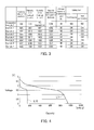
- FIG. 3 shows results of the initial capacity evaluation, nail penetration test, overcharge test, and evaluation of life characteristics at normal temperature.
- overcharge test each secondary battery, in which no abnormality was caused, is indicated as "OK"
- each secondary battery, in which any abnormality (swelling, breakage, etc.) was caused is indicated as "NG”.
- nail penetration test each secondary battery, in which no change in temperature and outer appearance was caused, is indicated as "OK"
- each secondary battery, in which any change in temperature or outer appearance was caused is indicated as "NG”.
- Example 1 Contact between the positive and negative electrodes (short-circuit), for example, can generate Joule heat. By this heat, a material having low thermal resistivity (separator) can be melted to form a stiff short circuit part. This may lead to continuous generation of the Joule heat to overheat the positive electrode. As a result, the positive electrode can reach a thermally unstable region (over 160°C). For this reason, lithium ion batteries as in Comparative Example 1 require various treatment in order to fully ensure its safety. By contrast, hybrid batteries as in Example 1 can ensure their safety easily. Further, Example 1 require electrolyte only to the amount to apply to the surface of a ceramic layer (isolation layer 30). Therefore, the flammability is lowered more than that in Comparative Example 1.
- the binding agent will be examined next.
- the battery in Comparative Example 1 which uses PVDF as the positive electrode binding agent, could not suppress overheating when the nail penetrating speed was reduced.
- the secondary battery in Comparative Example 1 was disassembled and examined to find that the active material fell off from the aluminum foil (current collector). The reason of this might be as follows.
- the short-circuit might have generated Joule heat to melt PVDF (crystalline melting point of 174°C), thereby deforming the positive electrode.
- PVDF crystalline melting point of 174°C
- the resistance might have been reduced to cause the electric current to further easily flow. This might have accelerated overheating to deform the positive electrode.
- the binding agent for the electrodes a substance that is hardly burnt down and melted is desirable.
- the binding agent for the electrodes is preferably composed of amorphous rubber macromolecules having high thermal resistance (320°C) and having a polyacrylonitrile unit.
- rubber macromolecules have rubber elasticity and can be easily bent. Therefore, the rubber macromolecules are effective in batteries of winding type.
- a binding agent with a nitrile group exemplified by a polyacrylonitrile group prevents holes from moving a little in semiconductor and is therefore excellent in electrical characteristics.
- FIG. 4 shows discharge capacity at 1 C in Example 1 and Comparative Example 1.
- the lines L1 and L10 indicate data of Example 1 and Comparative Example 1, respectively.
- Example 1 It can be understood from FIG. 4 that the secondary battery in Example 1 can exhibit high capacity.
- a porous ceramic layer (isolation layer 30), which corresponds to a hole transport layer, is provided between a p-type semiconductor layer (electrode 10) and a n-type semiconductor layer (electrode 20) in Example 1.
- the ceramic layer is bonded to the n-type semiconductor layer.
- the battery in Example 1 can exhibit both quick input/output as a feature of a semiconductor battery and high capacity as a feature of a lithium battery.
- movement of electrical charge (ion movement) in charge/discharge is insufficient because of rate limiting in a dissociation reaction, which serves as inhibitor of ion movement, or resistance generated when a composite of an organic substance and ions moves.
- both hole movement and ion movement contribute to charge/discharge in the battery in Example 1. Accordingly, cations of graphene and silicon oxide could be received much more. This might have resulted in that the battery in Example 1 could attain high capacity, which is seven times that of the battery in Comparative Example 1 (see FIG. 4 ).
- the battery in Example 1 had high input/output characteristics as a feature of a semiconductor battery. As shown in FIG. 3 , the battery in Example 1 had more excellent performance (high output performance) than the battery in Comparative Example 1 in capacity ratio of 10 C/1 C (discharge capacity ratio).
- the ions and holes are transmitted through the ion transmission member and the hole transmission member in both charge and discharge in the above embodiment.
- the present invention is not limited to this, and only one of the ions and the holes may be transmitted in charge or discharge.
- only the holes may be transmitted through the hole transmission member in discharge.
- only the transmitted ions may be transmitted through the ion transmission member in charge.
- Only one member may have both the functions of ion transmission and hole transmission. Further, the hole transmission member may be formed integrally with the ion transmission member.
- the isolation layer 30 covers the entire surface of the electrode 20, which however, should not be taken to limit the present invention.
- the isolation layer 30 may not cover the side surface of the electrode 20 which does not face the electrode 10.
- the isolation layer 30 is applied to the electrode 20 (negative electrode) to be layered, which however, should not be taken to limit the present invention. Rather than to the electrode 20 (negative electrode), the isolation layer 30 may be applied to the electrode 10 (positive electrode) to be layered. Alternatively, the isolation layer 30 may be layered on both the electrode 20 (negative electrode) and the electrode 10 (positive electrode).
- the secondary battery according to the present invention can attain high output and high capacity and is therefore suitably applicable to large-size storage batteries.
- the secondary battery according to the present invention are suitably employable as a storage battery in an electric power generating mechanism of which output is unstable, such as geothermal power generation, wind power generation, solar power generation, water power generation, and wave power generation.
- the secondary battery according to the present invention can be suitably employed in mobile entities, such as electric vehicles.
Landscapes
- Chemical & Material Sciences (AREA)
- Chemical Kinetics & Catalysis (AREA)
- Electrochemistry (AREA)
- General Chemical & Material Sciences (AREA)
- Inorganic Chemistry (AREA)
- Engineering & Computer Science (AREA)
- Materials Engineering (AREA)
- Composite Materials (AREA)
- Manufacturing & Machinery (AREA)
- Crystallography & Structural Chemistry (AREA)
- Battery Electrode And Active Subsutance (AREA)
- Secondary Cells (AREA)
Applications Claiming Priority (1)
| Application Number | Priority Date | Filing Date | Title |
|---|---|---|---|
| CN201310234957.8A CN104241679A (zh) | 2013-06-14 | 2013-06-14 | 二次电池 |
Publications (1)
| Publication Number | Publication Date |
|---|---|
| EP2814084A1 true EP2814084A1 (fr) | 2014-12-17 |
Family
ID=49117625
Family Applications (1)
| Application Number | Title | Priority Date | Filing Date |
|---|---|---|---|
| EP13003238.6A Withdrawn EP2814084A1 (fr) | 2013-06-14 | 2013-06-25 | Batterie secondaire |
Country Status (6)
| Country | Link |
|---|---|
| US (1) | US20140370381A1 (fr) |
| EP (1) | EP2814084A1 (fr) |
| JP (1) | JP2015002168A (fr) |
| KR (1) | KR20140145913A (fr) |
| CN (1) | CN104241679A (fr) |
| TW (1) | TW201508976A (fr) |
Families Citing this family (9)
| Publication number | Priority date | Publication date | Assignee | Title |
|---|---|---|---|---|
| JP6567546B2 (ja) * | 2014-04-21 | 2019-08-28 | 厦▲門▼大学 | 硫黄系遷移金属複合負極活物質、対応する負極および対応する電池 |
| WO2016114321A1 (fr) * | 2015-01-15 | 2016-07-21 | 中島 潤二 | Batterie secondaire |
| CN106653378B (zh) * | 2016-01-30 | 2020-01-14 | 徐跃 | 储存和释放电能的层合装置 |
| JP6939035B2 (ja) * | 2017-04-07 | 2021-09-22 | トヨタ自動車株式会社 | 全固体電池 |
| CN109326773B (zh) * | 2017-08-01 | 2021-12-28 | 天极新能源实业(深圳)有限公司 | 一种电极活性材料、电池电极及半导体纳米电池 |
| JP6518734B2 (ja) * | 2017-08-03 | 2019-05-22 | 株式会社パワーフォー | 二次電池 |
| WO2020137912A1 (fr) * | 2018-12-28 | 2020-07-02 | 株式会社パワーフォー | Batterie secondaire |
| JP6836281B2 (ja) * | 2018-12-28 | 2021-02-24 | 株式会社パワーフォー | 二次電池 |
| JP7550431B2 (ja) * | 2020-03-25 | 2024-09-13 | 株式会社パワーフォー | 二次電池 |
Citations (6)
| Publication number | Priority date | Publication date | Assignee | Title |
|---|---|---|---|---|
| JPH05242911A (ja) | 1992-02-28 | 1993-09-21 | Sanyo Electric Co Ltd | リチウムイオン二次電池 |
| US20040005265A1 (en) * | 2001-12-21 | 2004-01-08 | Massachusetts Institute Of Technology | Conductive lithium storage electrode |
| WO2009026467A1 (fr) * | 2007-08-21 | 2009-02-26 | A123 Systems Inc. | Séparateur pour pile électrochimique et procédé pour sa fabrication |
| US20090291367A1 (en) * | 2008-05-20 | 2009-11-26 | Toyota Jidosha Kabushiki Kaisha | Lithium secondary battery and method of manufacturing same |
| US20090325064A1 (en) * | 2008-06-26 | 2009-12-31 | Samsung Sdi Co., Ltd. | Electrode assembly and lithium secondary battery having the same |
| US20110239446A1 (en) * | 2008-12-26 | 2011-10-06 | Ryuta Morishima | Method for manufacturing nonaqueous secondary battery electrode |
Family Cites Families (14)
| Publication number | Priority date | Publication date | Assignee | Title |
|---|---|---|---|---|
| US6365299B1 (en) * | 1995-06-28 | 2002-04-02 | Fuji Photo Film Co., Ltd. | Nonaqueous secondary battery |
| JP3045998B2 (ja) * | 1997-05-15 | 2000-05-29 | エフエムシー・コーポレイション | 層間化合物およびその作製方法 |
| JP2001035481A (ja) * | 1999-07-12 | 2001-02-09 | Mitsubishi Chemicals Corp | 均一ドープト電極を有する電池およびその製造方法 |
| US20080057386A1 (en) * | 2002-10-15 | 2008-03-06 | Polyplus Battery Company | Ionically conductive membranes for protection of active metal anodes and battery cells |
| KR100745733B1 (ko) * | 2005-09-23 | 2007-08-02 | 삼성에스디아이 주식회사 | 음극 활물질, 그의 제조방법 및 이를 채용한 리튬 전지 |
| JP5103945B2 (ja) * | 2006-03-31 | 2012-12-19 | ソニー株式会社 | 非水電解質二次電池 |
| US8137844B2 (en) * | 2006-11-17 | 2012-03-20 | Nippon Chemical Industrial Co., Ltd. | Cathode active material for lithium rechargeable battery, manufacturing method thereof and lithium rechargeable battery |
| JP4293247B2 (ja) * | 2007-02-19 | 2009-07-08 | ソニー株式会社 | 積層型非水電解質電池およびその製造方法 |
| JP2009076372A (ja) * | 2007-09-21 | 2009-04-09 | Shin Etsu Chem Co Ltd | 非水系二次電池 |
| JP2010160984A (ja) * | 2009-01-08 | 2010-07-22 | Nissan Motor Co Ltd | リチウムイオン二次電池用負極およびこれを用いたリチウムイオン二次電池 |
| EP2287946A1 (fr) * | 2009-07-22 | 2011-02-23 | Belenos Clean Power Holding AG | Nouveaux matériaux d'électrode, en particulier pour des batteries rechargeables aux ions lithium |
| WO2012014255A1 (fr) * | 2010-07-29 | 2012-02-02 | 三菱重工業株式会社 | Batterie secondaire aux ions de lithium |
| JP2013054958A (ja) * | 2011-09-05 | 2013-03-21 | Hitachi Maxell Energy Ltd | 非水電解質二次電池用負極材、リチウムイオン二次電池及び電気化学キャパシタ |
| JP2013114983A (ja) * | 2011-11-30 | 2013-06-10 | Hitachi Maxell Ltd | 非水電解質電池 |
-
2013
- 2013-06-14 CN CN201310234957.8A patent/CN104241679A/zh active Pending
- 2013-06-25 US US13/926,877 patent/US20140370381A1/en not_active Abandoned
- 2013-06-25 EP EP13003238.6A patent/EP2814084A1/fr not_active Withdrawn
- 2013-06-26 TW TW102122749A patent/TW201508976A/zh unknown
- 2013-06-27 KR KR20130074436A patent/KR20140145913A/ko not_active Withdrawn
- 2013-06-27 JP JP2013134732A patent/JP2015002168A/ja active Pending
Patent Citations (6)
| Publication number | Priority date | Publication date | Assignee | Title |
|---|---|---|---|---|
| JPH05242911A (ja) | 1992-02-28 | 1993-09-21 | Sanyo Electric Co Ltd | リチウムイオン二次電池 |
| US20040005265A1 (en) * | 2001-12-21 | 2004-01-08 | Massachusetts Institute Of Technology | Conductive lithium storage electrode |
| WO2009026467A1 (fr) * | 2007-08-21 | 2009-02-26 | A123 Systems Inc. | Séparateur pour pile électrochimique et procédé pour sa fabrication |
| US20090291367A1 (en) * | 2008-05-20 | 2009-11-26 | Toyota Jidosha Kabushiki Kaisha | Lithium secondary battery and method of manufacturing same |
| US20090325064A1 (en) * | 2008-06-26 | 2009-12-31 | Samsung Sdi Co., Ltd. | Electrode assembly and lithium secondary battery having the same |
| US20110239446A1 (en) * | 2008-12-26 | 2011-10-06 | Ryuta Morishima | Method for manufacturing nonaqueous secondary battery electrode |
Non-Patent Citations (4)
| Title |
|---|
| HUNGRU CHEN ET AL: "Charge disproportionation and Jahn-Teller distortion in LiNiO_{2} and NaNiO_{2}: A density functional theory study", PHYSICAL REVIEW B, vol. 84, no. 8, 1 August 2011 (2011-08-01), pages 085108, XP055115613, ISSN: 1098-0121, DOI: 10.1103/PhysRevB.84.085108 * |
| MIN KIM ET AL: "Electrochemical performances of inorganic membrane coated electrodes for Li-ion batteries", JOURNAL OF SOLID STATE ELECTROCHEMISTRY ; CURRENT RESEARCH AND DEVELOPMENT IN SCIENCE AND TECHNOLOGY, SPRINGER, BERLIN, DE, vol. 14, no. 5, 5 May 2009 (2009-05-05), pages 769 - 773, XP019762811, ISSN: 1433-0768 * |
| PING CUI ET AL: "Preparation and characteristics of Sb-doped LiNiO2 cathode materials for Li-ion batteries", JOURNAL OF PHYSICS AND CHEMISTRY OF SOLIDS, PERGAMON PRESS, LONDON, GB, vol. 72, no. 7, 22 April 2011 (2011-04-22), pages 899 - 903, XP028095128, ISSN: 0022-3697, [retrieved on 20110429], DOI: 10.1016/J.JPCS.2011.04.013 * |
| TUKAMOTO H ET AL: "Electronic Conductivity of LiCoO2 and Its Enhancement by Magnesium Doping", JOURNAL OF THE ELECTROCHEMICAL SOCIETY, ELECTROCHEMICAL SOCIETY, MANCHESTER, NEW HAMPSHIRE; US, vol. 144, no. 9, 1 September 1997 (1997-09-01), pages 3164 - 3168, XP002962950, ISSN: 0013-4651 * |
Also Published As
| Publication number | Publication date |
|---|---|
| KR20140145913A (ko) | 2014-12-24 |
| US20140370381A1 (en) | 2014-12-18 |
| TW201508976A (zh) | 2015-03-01 |
| JP2015002168A (ja) | 2015-01-05 |
| CN104241679A (zh) | 2014-12-24 |
Similar Documents
| Publication | Publication Date | Title |
|---|---|---|
| US20140370381A1 (en) | Secondary battery | |
| JP6706461B2 (ja) | 二次電池用負極活物質、二次電池用負極、二次電池、電池パック、電動車両、電力貯蔵システム、電動工具および電子機器 | |
| JP4905267B2 (ja) | 正極合剤および非水電解質電池 | |
| US11695119B2 (en) | Negative electrode for secondary battery, secondary battery, battery pack, electric vehicle, power storage system, power tool, and electronic device | |
| EP3553850A1 (fr) | Accumulateur | |
| EP3525262A1 (fr) | Batterie secondaire, bloc-batterie, véhicule électrique, système de stockage d'électricité, outil électrique, et appareil électronique | |
| JP2008041465A (ja) | 非水電解質二次電池用負極、その製造方法及び非水電解質二次電池 | |
| CN107004854B (zh) | 二次电池活性物质、电极、二次电池、电池组、电动车辆、蓄电系统、电动工具及电子装置 | |
| EP2814093A1 (fr) | Matériau actif d'électrode positive et batterie secondaire | |
| EP2814094A1 (fr) | Électrode pour batterie secondaire et batterie secondaire | |
| WO2016114321A1 (fr) | Batterie secondaire | |
| JP2008041502A (ja) | 非水電解質二次電池用正極、その製造方法及び非水電解質二次電池 | |
| US20140370360A1 (en) | Secondary battery | |
| JP2009206092A (ja) | 非水電解質電池および正極ならびにこれらの製造方法 | |
| JP2009054469A (ja) | 非水二次電池 | |
| US11228025B2 (en) | Anode for secondary battery, secondary battery, battery pack, electric motor vehicle, power storage system, electric tool, and electronic device | |
| EP2814092A1 (fr) | Batterie secondaire et électrode pour batterie secondaire | |
| CN108400331B (zh) | 二次电池 | |
| KR102171213B1 (ko) | 리튬 이온 이차 전지용 부극, 리튬 이온 이차 전지, 전지 팩, 전동 차량, 전력 저장 시스템, 전동 공구 및 전자 기기 |
Legal Events
| Date | Code | Title | Description |
|---|---|---|---|
| 17P | Request for examination filed |
Effective date: 20130625 |
|
| AK | Designated contracting states |
Kind code of ref document: A1 Designated state(s): AL AT BE BG CH CY CZ DE DK EE ES FI FR GB GR HR HU IE IS IT LI LT LU LV MC MK MT NL NO PL PT RO RS SE SI SK SM TR |
|
| AX | Request for extension of the european patent |
Extension state: BA ME |
|
| PUAI | Public reference made under article 153(3) epc to a published international application that has entered the european phase |
Free format text: ORIGINAL CODE: 0009012 |
|
| RAP1 | Party data changed (applicant data changed or rights of an application transferred) |
Owner name: NAKAJIMA, JUNJI Owner name: FUJIWARA, YOSHIMASA |
|
| RIN1 | Information on inventor provided before grant (corrected) |
Inventor name: NAKAJIMA, JUNJI Inventor name: MENGQUN, SI |
|
| R17P | Request for examination filed (corrected) |
Effective date: 20150617 |
|
| RBV | Designated contracting states (corrected) |
Designated state(s): AL AT BE BG CH CY CZ DE DK EE ES FI FR GB GR HR HU IE IS IT LI LT LU LV MC MK MT NL NO PL PT RO RS SE SI SK SM TR |
|
| R17P | Request for examination filed (corrected) |
Effective date: 20150617 |
|
| RIN1 | Information on inventor provided before grant (corrected) |
Inventor name: NAKAJIMA, JUNJI Inventor name: MENGQUN, SI |
|
| STAA | Information on the status of an ep patent application or granted ep patent |
Free format text: STATUS: THE APPLICATION HAS BEEN WITHDRAWN |
|
| 18W | Application withdrawn |
Effective date: 20170524 |