EP2814111B1 - Ensemble de résonance - Google Patents
Ensemble de résonance Download PDFInfo
- Publication number
- EP2814111B1 EP2814111B1 EP13305802.4A EP13305802A EP2814111B1 EP 2814111 B1 EP2814111 B1 EP 2814111B1 EP 13305802 A EP13305802 A EP 13305802A EP 2814111 B1 EP2814111 B1 EP 2814111B1
- Authority
- EP
- European Patent Office
- Prior art keywords
- resonance post
- post
- frequency
- resonance
- resonator
- Prior art date
- Legal status (The legal status is an assumption and is not a legal conclusion. Google has not performed a legal analysis and makes no representation as to the accuracy of the status listed.)
- Active
Links
- 230000000712 assembly Effects 0.000 claims description 4
- 238000000429 assembly Methods 0.000 claims description 4
- 230000008878 coupling Effects 0.000 description 7
- 238000010168 coupling process Methods 0.000 description 7
- 238000005859 coupling reaction Methods 0.000 description 7
- 238000013459 approach Methods 0.000 description 6
- 230000005540 biological transmission Effects 0.000 description 4
- 239000003990 capacitor Substances 0.000 description 4
- 238000001914 filtration Methods 0.000 description 4
- 230000007246 mechanism Effects 0.000 description 4
- 230000001419 dependent effect Effects 0.000 description 3
- 230000005684 electric field Effects 0.000 description 3
- 238000010276 construction Methods 0.000 description 2
- 230000000694 effects Effects 0.000 description 2
- 238000004519 manufacturing process Methods 0.000 description 2
- 239000000463 material Substances 0.000 description 2
- 238000000034 method Methods 0.000 description 2
- 230000035515 penetration Effects 0.000 description 2
- RYGMFSIKBFXOCR-UHFFFAOYSA-N Copper Chemical compound [Cu] RYGMFSIKBFXOCR-UHFFFAOYSA-N 0.000 description 1
- 238000004458 analytical method Methods 0.000 description 1
- 229910010293 ceramic material Inorganic materials 0.000 description 1
- 230000008859 change Effects 0.000 description 1
- 238000004891 communication Methods 0.000 description 1
- 229910052802 copper Inorganic materials 0.000 description 1
- 239000010949 copper Substances 0.000 description 1
- 230000003247 decreasing effect Effects 0.000 description 1
- 238000005516 engineering process Methods 0.000 description 1
- 239000000203 mixture Substances 0.000 description 1
- 230000009467 reduction Effects 0.000 description 1
- 238000000926 separation method Methods 0.000 description 1
- 229910052709 silver Inorganic materials 0.000 description 1
- 239000004332 silver Substances 0.000 description 1
- 238000004088 simulation Methods 0.000 description 1
- 238000005476 soldering Methods 0.000 description 1
- 238000001228 spectrum Methods 0.000 description 1
Images




Classifications
-
- H—ELECTRICITY
- H01—ELECTRIC ELEMENTS
- H01P—WAVEGUIDES; RESONATORS, LINES, OR OTHER DEVICES OF THE WAVEGUIDE TYPE
- H01P1/00—Auxiliary devices
- H01P1/20—Frequency-selective devices, e.g. filters
- H01P1/201—Filters for transverse electromagnetic waves
- H01P1/205—Comb or interdigital filters; Cascaded coaxial cavities
- H01P1/2053—Comb or interdigital filters; Cascaded coaxial cavities the coaxial cavity resonators being disposed parall to each other
-
- H—ELECTRICITY
- H01—ELECTRIC ELEMENTS
- H01P—WAVEGUIDES; RESONATORS, LINES, OR OTHER DEVICES OF THE WAVEGUIDE TYPE
- H01P7/00—Resonators of the waveguide type
- H01P7/04—Coaxial resonators
Definitions
- the present invention relates to a resonant assembly.
- Resonant devices are known. In low-frequency electronics, a resonant circuit contains a capacitor and a coil. The capacitor is used to store electrical energy and the coil stores magnetic energy. At resonance, energy stored in the resonant circuit is continuously converted between two states, swapping between capacitor and coil over time. At higher frequencies, transmission lines can resonate. A quarter-wavelength transmission line with one end grounded and the other end open can be seen as a combination of a capacitor and coil. Increasing the permittivity of the transmission line by using, for example, ceramic materials reduces the size of the resonant device. Resonant devices are often used in radio-frequency (RF) front ends. Each resonant device has its own characteristics, including its own resonance frequency. The resonance frequency is dependent on the characteristics of the device and, in particular, on the characteristics of the mixtures of various materials making up the device.
- RF radio-frequency
- WO2009/056813 discloses a tunable filter with a cavity and two resonant posts therein, the coupling between the two resonators and/or the resonant frequency of the second resonator can be tuned to tune both the central operating frequency and the bandwidth of the filter.
- WO2013/036485 discloses an open circuit common junction feed for a duplexer, comprising a combline cavity filter comprising a plurality of resonator posts, tuning screws are used to tune one half to one frequency and the other half to another frequency a central post being a common resonator.
- US2012/0249266 discloses an RF filter cavity for adjusting coupling amount or transmission zero. It comprises a plurality of cavities each with a single post therein.
- WO 2009/067056 discloses a dual-mode filter comprising a cavity with two or more resonant rods arranged orthoganally to each other.
- JP2002 359502 discloses a dielectric resonator band-pass filter with two dielectric resonators and coupling elements for coupling radio waves excited on one of the dielectric resonators to the other dielectric resonator.
- a resonator assembly comprising: a resonator having a first resonance post coaxially surrounded by a conductive enclosure defining a cavity, the first resonance post being operable to filter a signal at a first frequency and a second resonance post located within the cavity, the second resonance post being operable to filter the signal at a second frequency;
- the first aspect recognises that conventional resonators such as, for example, a Transverse ElectroMagnetic (TEM) combline resonator shown in Figure 1 , consists of a metallic cavity enclosure (with a generally circular-shaped or rectangular-shaped cross section) with a cylindrical-shaped metallic post at the centre of the circular/rectangular cavity grounded at one side and open-ended at the opposite side.
- TEM Transverse ElectroMagnetic
- Each of these resonators is dimensioned to provide a resonance at a particular desired frequency.
- the first aspect recognises that it is possible to reuse the cavity in order provide a resonator which provides a resonance at more than one particular desired frequency.
- a resonator assembly may be provided.
- the assembly comprises a resonator which has a first resonance post or element which is surrounded or enclosed by a conductive enclosure or housing.
- the conductive enclosure defines a cavity.
- the first resonance post resonates or filters a signal at a first frequency.
- the assembly comprises a resonator which has a second resonance post or element located within the cavity.
- the second resonance post resonates or filters a signal at a second frequency.
- the second frequency is greater than the first frequency. Harmonics of the first frequency fail to coincide with harmonics of the second frequency.
- the second frequency and the first frequency have no common harmonics.
- the first resonance post is located centrally within the conductive enclosure and the second resonance post is located away from the first resonance post and towards the conductive enclosure. Accordingly, the second resonance post may reuse part of the cavity.
- At least one of the first resonance post and the second resonance post is configured to have a variable length.
- a dedicated tuning mechanism for each resonance is provided. By varying the length, the frequency may be tuned.
- At least one of the first resonance post and the second resonance post comprises a first portion displaceable with respect to a second portion to vary its length.
- the first portion is received within the second portion.
- the second portion comprises a post having a cavity extending therethrough for receiving the first portion therewithin.
- the first portion comprises a screw received within a screw thread formed within the cavity, the first portion being protrudable from the second portion to vary its length.
- individual physically separated filter cavities for each frequency band are built and these then are tuned independently.
- these resonances are tuned by tuning screws which protrude through a cavity wall or thorough the cavity cover into the cavity, located close to the region with the highest electrical field of the according resonant mode.
- this approach is often not possible or implies restrictions on the resonator layout, particularly for the resonant mode for the higher frequency which is excited on the shorter resonator post.
- a long tuning screw would have a negative impact on the Q-factor of the resonator or would even result in a complete detuning of the resonator.
- a tuning screw from the side, but usually in more complex structures, e.g. in a filter-configuration, where several cavities are placed next to each other, this is not possible, since two rows of resonators are placed in parallel, making it impossible to place tuning screws from the side.
- a second aspect provides a filter comprising a plurality of the resonator assemblies of the first aspect adjacently located and having shared portions of the conductive enclosure, and wherein the second resonance post in each resonance assembly is located towards the shared portions of the conductive enclosure.
- the cavity of a resonator is reused to co-house a further resonator.
- This provides a device which is able to provide resonance at multiple frequencies without needing to provide multiple devices, each with their own housing. Instead, the resonators are co-located within the same housing. This enables a single device to be provided which operates in same way as a plurality of different resonators, but with a significantly reduced size compared to providing separate resonators.
- the resonator structures can have similar permittivity and can vary their resonant frequency by varying their length, varying the permittivity of the different resonator structures enables similar-sized structures to resonate at different frequencies.
- the embodiments described below provide for a two-frequency resonator, it will be appreciated that by adding additional resonator structures within the housing enables a more than two-frequency resonator to be provided.
- Figure 2 illustrates a dual-frequency combline resonator according to one embodiment.
- This arrangement utilizes the physical space provided by the single, in this example, rectangular, cavity provided in a combline package to include an additional metallic cylindrical post offset from a central location and towards a corner of the rectangular cavity. This is to introduce an additional electromagnetic resonance at a higher frequency.
- a rectangular package is shown, it will be appreciated that any other configuration which provides a coaxial arrangement between the metallic cylindrical post at the central location and a surrounding conductive enclosure could be used.
- the posts illustrated are cylindrical, it will be appreciated that non-cylindrical posts may be used.
- this arrangement creates two electromagnetic (EM) resonances at distinct frequencies, f 1 (a lower frequency due to the centre metallic post) and f 2 (a higher frequency due to the corner metallic post).
- the centre metallic post within the rectangular metallic cavity with the corner metallic post present resonates at a frequency f 1 (which is slightly different to the frequency at which it would resonate if it were alone within the cavity), whereas the metallic post at the corner within the cavity with the metallic post at the centre present resonates at a higher desired frequency f 2 ( f 2 > f 1 ).
- the corner metallic post's physical size is a fraction of the centre metallic post's size. This ratio is proportional (within limitations of the frequency ratio f 2 / f 1 and specific technology implementation variations) to the ratio of frequencies f 1 and f 2 .
- This arrangement enables two electromagnetic resonances at distinct frequencies in a single physical volume within a single metallic enclosure in a combline package.
- this arrangement provides for dual-posts in a single cavity; a centre post for lower frequency operation and a corner post for higher frequency operation.
- this arrangement provides for the spatial separation of the resonance field distribution to allow for independent control of input/output coupling/tuning/inter-resonator coupling.
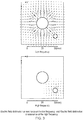
- Figures 3 and 4 show the EM field distribution for the two resonant modes.
- Table 1 summarizes the resonant frequency and Q-factor of the first 3 eigenmodes of the standalone low-band combline resonator, standalone high-band resonator and combined resonator of Figure 2 .
- Table 1 Resonant frequency and Q-factor for the first 3 eigenmodes of the standalone low-band cavity, standalone high-band cavity, and combined low+high-band cavity Mode 1 Mode 2 Mode 3 f 0 (MHz) Q 0 f 0 (MHz) Q 0 f 0 (MHz) Q 0 Low 695.792 6407 2061.33 11389 2223.42 13850 High 1792.12 4004 5237.13 7026 5722.69 8652 Low 696.044 6186 f 0 (%) 1769.86 4449 f 0 (%) 2065.57 11243 f 0 (%) + 0.04 U 1.24 D 0.26 High Q 0 (%) Q 0 (%) 3.45 D 11.1 U
- the low frequency resonance of the combined cavity resonator is not affected as compared to the standalone low frequency cavity resonator.
- the Q-factor is slightly decreased (3.45 %).
- the high-frequency resonance is not affected, whereas the Q-factor has been increased significantly (11.1 %). This is due to the greater electrical size of the host cavity.
- the first harmonic resonance frequency of the standalone low-band resonator is not significantly affected by the inclusion of the high-band metallic post, thus does not create problems for the high-band resonance of the combined cavity.
- Figures 5 and 6 illustrate three feeding pin configurations according to embodiments.
- Figures 5a / 6a would be suitable for an inline configuration
- Figures 5b / 6b would suit a folded configuration
- Figures 5c / 6c show a suitable configuration for dual-band filters.
- a combination of Figures 5c / 6c with either Figures 5b / 6b or Figures 5a / 6a would be suitable for a duplexer configuration.
- the inner core of the coaxial feed is shown coupled towards the base of each post.
- an alternative well-known approach would be instead to couple towards the top of the post via spaced coin or capacitive disc arrangement.
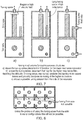
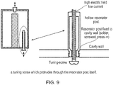
- Figure 7 illustrates an arrangement for tuning of the resonant frequencies. Unlike for the central resonator post where it is possible to tune its resonant frequency using a screw which projects towards the top of the post as shown in Figure 7 , this approach is not practical for the offset resonator post as the long length of such a screw would affect the characteristics of the central resonator post. Also, it is not possible to provide a screw extending towards the offset resonator post through the conductive wall and still retain access to that screw in a multi-stage resonator as shown in Figure 8 . Hence, in order to provide for tuning of the resonant frequencies, a tuning screw, which reaches through the resonator post, and out of the top of the resonator post is provided.
- a hollow resonator post through which a screw from the underside passes through.
- the pass-through of the screw can be implemented is various ways, for example, with a thread at both ends of the resonator tube or only on the top end of the resonator post.
- the resonator post can be mounted to the resonator wall in different ways, for example, by a press-in-fit, by a thread or by soldering, other methods are possible. Also various methods can be used to ensure a good electrical and mechanical contact, for example, by spring loaded counter-screws at the bottom of the resonators post.
- Figure 10 illustrates the independent control of the tuning for individual resonances utilizing the tuning screws. This is of paramount importance in order to achieve dual-frequency filter solutions with minimum tuning complexity comparable to the tuning complexity of the two distinct cavity/frequency filters.
- Figure 10a shows the resonant frequency normalized to resonant frequency with no screw as a function of low-band screw penetration (mm) for low-band (solid line) and for high-band (dashed line).
- Figure 10b shows the resonant frequency normalized to resonant frequency with no screw as a function of high-band screw penetration (mm) for high-band (solid line) and for low-band (dashed line).
- Such an arrangement enables a resonator in a cavity which is relatively much higher than the resonator post is long, to be tuned mechanically and electrically in a very effective and simple way. If implemented on both resonators, the tuning of both frequencies from only one side is possible; if implemented in such a way that one resonator is tuned from the top side and one from the lower side, this will reduce the density of screws on the respective side and allow for dense resonator configurations.
- This enables the construction of structures, which consist of multiple dual-resonance structures, which are not limited in their construction by requiring any tuning mechanisms from the side of the resonator. This allows the implementation of complex tuneable dual-resonance structures like filters in a very compact form factor, saving volume, weight and cost.
- embodiments provide an arrangement having a reduced physical size but enabling two distinct resonant frequencies to coexist at the expense of slightly higher manufacturing and design complexity.
- no additional physical space is required for the high band resonant structure ( f 2 ). Instead this is incorporated into the low band resonant structure (at f 1 ) without any additional physical space requirement.
- This provides an arrangement which offers high Q-factor (at f 2 ) with no additional physical space requirements.
- the additional physical space of the combined resonant structure allows for increase in the quality factor at the high frequency regime ( f 2 ) . This can allow for high performance filtering; required for narrow-band filter wireless telecommunication applications.
- the quality factors of the high frequency resonant structures are higher (represent lower ohmic loses) as compared with the standalone high filtering quality factors in the conventional filtering approaches. Also, due to the fact that additional physical space is inherent to the resonant structure for the high frequency, increase in the high power handling capabilities for terrestrial communication systems can be pursued. Furthermore, although there are additional costs of fabrication for a resonant structure at the high frequency there is an overall cost reduction due to the fact that only one resonant cavity needs to be fabricated instead of two.
Landscapes
- Physics & Mathematics (AREA)
- Electromagnetism (AREA)
- Control Of Motors That Do Not Use Commutators (AREA)
Claims (11)
- Ensemble résonateur, comprenant :un résonateur ayant une première tige de résonance entourée coaxialement par une enceinte conductrice définissant une cavité, ladite première tige de résonance pouvant fonctionner pour filtrer un signal à une première fréquence, et une seconde tige de résonance située à l'intérieur de ladite cavité, ladite seconde tige de résonance pouvant fonctionner pour filtrer le signal à une seconde fréquence ; dans lequellesdites première et seconde tiges de résonance sont configurées de telle sorte que les harmoniques de ladite première fréquence ne coïncident pas avec les harmoniques de ladite seconde fréquence et qu'un rapport de ladite seconde fréquence à ladite première fréquence ne soit pas proche de l'unité de telle sorte que les résonances de la cavité auxdites première et seconde fréquences ne soient pas couplées ; etladite première tige de résonance est située centralement à l'intérieur de ladite enceinte conductrice et ladite seconde tige de résonance est située à distance de ladite première tige de résonance et vers ladite enceinte conductrice ; et caractérisé en ce queladite première tige de résonance et ladite seconde tige de résonance se dressent à partir d'une même face de ladite enceinte conductrice.
- Ensemble résonateur selon la revendication 1, dans lequel ladite seconde fréquence est supérieure à ladite première fréquence.
- Ensemble résonateur selon l'une quelconque des revendications précédentes, dans lequel ladite première tige de résonance peut fonctionner pour transporter un signal à l'aide d'une première alimentation de signal et ladite seconde tige de résonance peut fonctionner pour transporter un signal à l'aide d'une seconde alimentation de signal, au moins une de ladite première alimentation de signal et de ladite seconde alimentation de signal étant fournie par le biais d'une base de ladite enceinte conductrice à partir de laquelle s'élève une tige respective de ladite première tige de résonance et de ladite seconde tige de résonance.
- Ensemble résonateur selon l'une quelconque des revendications précédentes, dans lequel ladite première tige de résonance et ladite seconde tige de résonance transportent un signal en utilisant une alimentation de signal commune positionnée entre ladite première tige de résonance et ladite seconde tige de résonance.
- Ensemble résonateur selon la revendication 4, dans lequel ladite alimentation de signal commune s'étend entre une base de ladite enceinte conductrice à partir de laquelle s'élèvent ladite première tige de résonance et ladite seconde tige de résonance et une face de ladite enceinte conductrice vers laquelle s'élèvent ladite première tige de résonance et ladite seconde tige de résonance.
- Ensemble résonateur selon l'une quelconque des revendications précédentes, dans lequel au moins une de ladite première tige de résonance et de ladite seconde tige de résonance est configurée pour avoir une longueur variable.
- Ensemble résonateur selon l'une quelconque des revendications précédentes, dans lequel au moins une de ladite première tige de résonance et de ladite seconde tige de résonance comprend une première partie déplaçable par rapport à une seconde partie pour faire varier sa longueur.
- Ensemble résonateur selon la revendication 7, dans lequel ladite première partie est reçue à l'intérieur de ladite seconde partie.
- Ensemble résonateur selon la revendication 7 ou 8, dans lequel ladite seconde partie comprend une tige à travers laquelle s'étend une cavité pour recevoir ladite première partie en son sein.
- Ensemble résonateur selon l'une quelconque des revendications 7 à 9, dans lequel ladite première partie comprend une vis reçue à l'intérieur d'un filetage formé à l'intérieur de ladite cavité, ladite première partie pouvant dépasser de ladite seconde partie pour faire varier sa longueur.
- Filtre comprenant une pluralité desdits ensembles résonateurs selon l'une quelconque des revendications précédentes, moyennant quoi lesdits ensembles résonateurs sont situés de manière adjacente et ont des parties partagées de ladite enceinte conductrice, et dans lequel ladite seconde tige de résonance dans chaque filtre de résonance est située vers lesdites parties partagées de ladite enceinte conductrice.
Priority Applications (2)
| Application Number | Priority Date | Filing Date | Title |
|---|---|---|---|
| EP13305802.4A EP2814111B1 (fr) | 2013-06-13 | 2013-06-13 | Ensemble de résonance |
| PCT/EP2014/001535 WO2014198397A1 (fr) | 2013-06-13 | 2014-06-05 | Ensemble résonant |
Applications Claiming Priority (1)
| Application Number | Priority Date | Filing Date | Title |
|---|---|---|---|
| EP13305802.4A EP2814111B1 (fr) | 2013-06-13 | 2013-06-13 | Ensemble de résonance |
Publications (2)
| Publication Number | Publication Date |
|---|---|
| EP2814111A1 EP2814111A1 (fr) | 2014-12-17 |
| EP2814111B1 true EP2814111B1 (fr) | 2020-03-18 |
Family
ID=48703376
Family Applications (1)
| Application Number | Title | Priority Date | Filing Date |
|---|---|---|---|
| EP13305802.4A Active EP2814111B1 (fr) | 2013-06-13 | 2013-06-13 | Ensemble de résonance |
Country Status (2)
| Country | Link |
|---|---|
| EP (1) | EP2814111B1 (fr) |
| WO (1) | WO2014198397A1 (fr) |
Families Citing this family (1)
| Publication number | Priority date | Publication date | Assignee | Title |
|---|---|---|---|---|
| EP3079198A1 (fr) * | 2015-04-09 | 2016-10-12 | Alcatel Lucent | Ensemble de résonateur et filtre |
Citations (2)
| Publication number | Priority date | Publication date | Assignee | Title |
|---|---|---|---|---|
| JP2002359502A (ja) * | 2001-03-27 | 2002-12-13 | Tamagawa Electronics Co Ltd | 誘電体共振器バンドパスフィルタ及び半同軸共振器バンドパスフィルタ |
| WO2009067056A1 (fr) * | 2007-11-20 | 2009-05-28 | Telefonaktiebolaget Lm Ericsson (Publ) | Filtre s'utilisant dans un réseau de communication sans fil |
Family Cites Families (6)
| Publication number | Priority date | Publication date | Assignee | Title |
|---|---|---|---|---|
| US2897364A (en) * | 1955-11-09 | 1959-07-28 | William C Farmer | Tuned band-pass crystal holder |
| DE102006061141B4 (de) * | 2006-12-22 | 2014-12-11 | Kathrein-Werke Kg | Hochfrequenzfilter mit Sperrkreiskopplung |
| GB0721361D0 (en) * | 2007-10-30 | 2007-12-12 | Radio Design Ltd | Tunable filter |
| EP2482377B1 (fr) * | 2011-01-26 | 2014-03-19 | Alcatel Lucent | Filtre RF doté d'un moyen de couplage pour signaux RF |
| US20120249266A1 (en) * | 2011-03-31 | 2012-10-04 | Ace Technologies Corporation | Rf filter for adjusting coupling amount or transmission zero |
| CN104170161A (zh) * | 2011-09-06 | 2014-11-26 | 电力波技术有限公司 | 用于双工器的开路公共结点馈电 |
-
2013
- 2013-06-13 EP EP13305802.4A patent/EP2814111B1/fr active Active
-
2014
- 2014-06-05 WO PCT/EP2014/001535 patent/WO2014198397A1/fr not_active Ceased
Patent Citations (2)
| Publication number | Priority date | Publication date | Assignee | Title |
|---|---|---|---|---|
| JP2002359502A (ja) * | 2001-03-27 | 2002-12-13 | Tamagawa Electronics Co Ltd | 誘電体共振器バンドパスフィルタ及び半同軸共振器バンドパスフィルタ |
| WO2009067056A1 (fr) * | 2007-11-20 | 2009-05-28 | Telefonaktiebolaget Lm Ericsson (Publ) | Filtre s'utilisant dans un réseau de communication sans fil |
Also Published As
| Publication number | Publication date |
|---|---|
| WO2014198397A1 (fr) | 2014-12-18 |
| EP2814111A1 (fr) | 2014-12-17 |
Similar Documents
| Publication | Publication Date | Title |
|---|---|---|
| EP2814112A1 (fr) | Ensemble de résonance | |
| US7310031B2 (en) | Dielectric resonators and circuits made therefrom | |
| US7183881B2 (en) | Cross-coupled dielectric resonator circuit | |
| RU2586272C2 (ru) | Рамочная антенна(варианты) | |
| KR100992089B1 (ko) | 대역 저지 필터 | |
| EP0827233B1 (fr) | Résonateur diélectrique à mode TM et filtre diélectrique à mode TM et duplexeur utilisant le résonateur | |
| US9641148B2 (en) | Resonator and filter having the same | |
| JPS61196603A (ja) | アンテナ | |
| US12444824B2 (en) | Resonator apparatus, filter apparatus as well as radio frequency and microwave device | |
| EP3104452A1 (fr) | Résonateur, filtre hyperfréquence et procédé de filtrage de fréquences radio | |
| US10033084B2 (en) | Operation frequency band customizable and frequency tunable filters with EBG substrates | |
| EP2800201B1 (fr) | Filtre à haute fréquence | |
| JP2008543192A (ja) | 同軸共振器に接続可能な端壁を備えたマイクロ波フィルタ | |
| EP2894710B1 (fr) | Filtre avec résonateurs coaxiales | |
| US10862183B2 (en) | Microwave bandpass filter comprising a conductive housing with a dielectric resonator therein and including an internal coupling element providing coupling between HEEx and HEEy modes | |
| CA2849854A1 (fr) | Filtre radiofrequence a element dielectrique | |
| EP2814111B1 (fr) | Ensemble de résonance | |
| EP1858109A1 (fr) | Résonateur diélectrique à double mode TE | |
| US10756403B2 (en) | Filter comprising resonator assemblies including a first cavity with a first resonant member and a second cavity with a second resonant member, where a part of the first cavity forms the second resonant member | |
| EP2894709B1 (fr) | Filtre avec résonateurs coaxiales | |
| del Castillo Velazquez-Ahumada et al. | Design of a dual band-pass filter using modified folded stepped-impedance resonators | |
| WO2005045985A1 (fr) | Filtre a accord variable a resonateurs dielectriques a couplage transversal | |
| CN112186323A (zh) | 微波谐振器和滤波器 | |
| Hung et al. | Fully reconfigurable evanescent mode bandpass filter embedded with metallic grid | |
| KR20110054899A (ko) | 고주파 필터 |
Legal Events
| Date | Code | Title | Description |
|---|---|---|---|
| 17P | Request for examination filed |
Effective date: 20140606 |
|
| AK | Designated contracting states |
Kind code of ref document: A1 Designated state(s): AL AT BE BG CH CY CZ DE DK EE ES FI FR GB GR HR HU IE IS IT LI LT LU LV MC MK MT NL NO PL PT RO RS SE SI SK SM TR |
|
| AX | Request for extension of the european patent |
Extension state: BA ME |
|
| PUAI | Public reference made under article 153(3) epc to a published international application that has entered the european phase |
Free format text: ORIGINAL CODE: 0009012 |
|
| RBV | Designated contracting states (corrected) |
Designated state(s): AL AT BE BG CH CY CZ DE DK EE ES FI FR GB GR HR HU IE IS IT LI LT LU LV MC MK MT NL NO PL PT RO RS SE SI SK SM TR |
|
| STAA | Information on the status of an ep patent application or granted ep patent |
Free format text: STATUS: EXAMINATION IS IN PROGRESS |
|
| 17Q | First examination report despatched |
Effective date: 20170811 |
|
| RAP1 | Party data changed (applicant data changed or rights of an application transferred) |
Owner name: ALCATEL LUCENT |
|
| GRAP | Despatch of communication of intention to grant a patent |
Free format text: ORIGINAL CODE: EPIDOSNIGR1 |
|
| STAA | Information on the status of an ep patent application or granted ep patent |
Free format text: STATUS: GRANT OF PATENT IS INTENDED |
|
| INTG | Intention to grant announced |
Effective date: 20190930 |
|
| RIN1 | Information on inventor provided before grant (corrected) |
Inventor name: DOUMANIS, EFSTRATIOS Inventor name: PIVIT, FLORIAN |
|
| GRAS | Grant fee paid |
Free format text: ORIGINAL CODE: EPIDOSNIGR3 |
|
| GRAA | (expected) grant |
Free format text: ORIGINAL CODE: 0009210 |
|
| STAA | Information on the status of an ep patent application or granted ep patent |
Free format text: STATUS: THE PATENT HAS BEEN GRANTED |
|
| AK | Designated contracting states |
Kind code of ref document: B1 Designated state(s): AL AT BE BG CH CY CZ DE DK EE ES FI FR GB GR HR HU IE IS IT LI LT LU LV MC MK MT NL NO PL PT RO RS SE SI SK SM TR |
|
| REG | Reference to a national code |
Ref country code: GB Ref legal event code: FG4D |
|
| REG | Reference to a national code |
Ref country code: DE Ref legal event code: R096 Ref document number: 602013066913 Country of ref document: DE |
|
| REG | Reference to a national code |
Ref country code: AT Ref legal event code: REF Ref document number: 1247002 Country of ref document: AT Kind code of ref document: T Effective date: 20200415 Ref country code: IE Ref legal event code: FG4D |
|
| PG25 | Lapsed in a contracting state [announced via postgrant information from national office to epo] |
Ref country code: RS Free format text: LAPSE BECAUSE OF FAILURE TO SUBMIT A TRANSLATION OF THE DESCRIPTION OR TO PAY THE FEE WITHIN THE PRESCRIBED TIME-LIMIT Effective date: 20200318 Ref country code: NO Free format text: LAPSE BECAUSE OF FAILURE TO SUBMIT A TRANSLATION OF THE DESCRIPTION OR TO PAY THE FEE WITHIN THE PRESCRIBED TIME-LIMIT Effective date: 20200618 Ref country code: FI Free format text: LAPSE BECAUSE OF FAILURE TO SUBMIT A TRANSLATION OF THE DESCRIPTION OR TO PAY THE FEE WITHIN THE PRESCRIBED TIME-LIMIT Effective date: 20200318 |
|
| REG | Reference to a national code |
Ref country code: NL Ref legal event code: MP Effective date: 20200318 |
|
| PG25 | Lapsed in a contracting state [announced via postgrant information from national office to epo] |
Ref country code: LV Free format text: LAPSE BECAUSE OF FAILURE TO SUBMIT A TRANSLATION OF THE DESCRIPTION OR TO PAY THE FEE WITHIN THE PRESCRIBED TIME-LIMIT Effective date: 20200318 Ref country code: SE Free format text: LAPSE BECAUSE OF FAILURE TO SUBMIT A TRANSLATION OF THE DESCRIPTION OR TO PAY THE FEE WITHIN THE PRESCRIBED TIME-LIMIT Effective date: 20200318 Ref country code: HR Free format text: LAPSE BECAUSE OF FAILURE TO SUBMIT A TRANSLATION OF THE DESCRIPTION OR TO PAY THE FEE WITHIN THE PRESCRIBED TIME-LIMIT Effective date: 20200318 Ref country code: BG Free format text: LAPSE BECAUSE OF FAILURE TO SUBMIT A TRANSLATION OF THE DESCRIPTION OR TO PAY THE FEE WITHIN THE PRESCRIBED TIME-LIMIT Effective date: 20200618 Ref country code: GR Free format text: LAPSE BECAUSE OF FAILURE TO SUBMIT A TRANSLATION OF THE DESCRIPTION OR TO PAY THE FEE WITHIN THE PRESCRIBED TIME-LIMIT Effective date: 20200619 |
|
| REG | Reference to a national code |
Ref country code: LT Ref legal event code: MG4D |
|
| PG25 | Lapsed in a contracting state [announced via postgrant information from national office to epo] |
Ref country code: NL Free format text: LAPSE BECAUSE OF FAILURE TO SUBMIT A TRANSLATION OF THE DESCRIPTION OR TO PAY THE FEE WITHIN THE PRESCRIBED TIME-LIMIT Effective date: 20200318 |
|
| PG25 | Lapsed in a contracting state [announced via postgrant information from national office to epo] |
Ref country code: SK Free format text: LAPSE BECAUSE OF FAILURE TO SUBMIT A TRANSLATION OF THE DESCRIPTION OR TO PAY THE FEE WITHIN THE PRESCRIBED TIME-LIMIT Effective date: 20200318 Ref country code: RO Free format text: LAPSE BECAUSE OF FAILURE TO SUBMIT A TRANSLATION OF THE DESCRIPTION OR TO PAY THE FEE WITHIN THE PRESCRIBED TIME-LIMIT Effective date: 20200318 Ref country code: EE Free format text: LAPSE BECAUSE OF FAILURE TO SUBMIT A TRANSLATION OF THE DESCRIPTION OR TO PAY THE FEE WITHIN THE PRESCRIBED TIME-LIMIT Effective date: 20200318 Ref country code: LT Free format text: LAPSE BECAUSE OF FAILURE TO SUBMIT A TRANSLATION OF THE DESCRIPTION OR TO PAY THE FEE WITHIN THE PRESCRIBED TIME-LIMIT Effective date: 20200318 Ref country code: SM Free format text: LAPSE BECAUSE OF FAILURE TO SUBMIT A TRANSLATION OF THE DESCRIPTION OR TO PAY THE FEE WITHIN THE PRESCRIBED TIME-LIMIT Effective date: 20200318 Ref country code: CZ Free format text: LAPSE BECAUSE OF FAILURE TO SUBMIT A TRANSLATION OF THE DESCRIPTION OR TO PAY THE FEE WITHIN THE PRESCRIBED TIME-LIMIT Effective date: 20200318 Ref country code: PT Free format text: LAPSE BECAUSE OF FAILURE TO SUBMIT A TRANSLATION OF THE DESCRIPTION OR TO PAY THE FEE WITHIN THE PRESCRIBED TIME-LIMIT Effective date: 20200812 Ref country code: IS Free format text: LAPSE BECAUSE OF FAILURE TO SUBMIT A TRANSLATION OF THE DESCRIPTION OR TO PAY THE FEE WITHIN THE PRESCRIBED TIME-LIMIT Effective date: 20200718 |
|
| REG | Reference to a national code |
Ref country code: AT Ref legal event code: MK05 Ref document number: 1247002 Country of ref document: AT Kind code of ref document: T Effective date: 20200318 |
|
| REG | Reference to a national code |
Ref country code: DE Ref legal event code: R097 Ref document number: 602013066913 Country of ref document: DE |
|
| PLBE | No opposition filed within time limit |
Free format text: ORIGINAL CODE: 0009261 |
|
| STAA | Information on the status of an ep patent application or granted ep patent |
Free format text: STATUS: NO OPPOSITION FILED WITHIN TIME LIMIT |
|
| PG25 | Lapsed in a contracting state [announced via postgrant information from national office to epo] |
Ref country code: ES Free format text: LAPSE BECAUSE OF FAILURE TO SUBMIT A TRANSLATION OF THE DESCRIPTION OR TO PAY THE FEE WITHIN THE PRESCRIBED TIME-LIMIT Effective date: 20200318 Ref country code: AT Free format text: LAPSE BECAUSE OF FAILURE TO SUBMIT A TRANSLATION OF THE DESCRIPTION OR TO PAY THE FEE WITHIN THE PRESCRIBED TIME-LIMIT Effective date: 20200318 Ref country code: DK Free format text: LAPSE BECAUSE OF FAILURE TO SUBMIT A TRANSLATION OF THE DESCRIPTION OR TO PAY THE FEE WITHIN THE PRESCRIBED TIME-LIMIT Effective date: 20200318 Ref country code: IT Free format text: LAPSE BECAUSE OF FAILURE TO SUBMIT A TRANSLATION OF THE DESCRIPTION OR TO PAY THE FEE WITHIN THE PRESCRIBED TIME-LIMIT Effective date: 20200318 Ref country code: MC Free format text: LAPSE BECAUSE OF FAILURE TO SUBMIT A TRANSLATION OF THE DESCRIPTION OR TO PAY THE FEE WITHIN THE PRESCRIBED TIME-LIMIT Effective date: 20200318 |
|
| REG | Reference to a national code |
Ref country code: CH Ref legal event code: PL |
|
| 26N | No opposition filed |
Effective date: 20201221 |
|
| PG25 | Lapsed in a contracting state [announced via postgrant information from national office to epo] |
Ref country code: PL Free format text: LAPSE BECAUSE OF FAILURE TO SUBMIT A TRANSLATION OF THE DESCRIPTION OR TO PAY THE FEE WITHIN THE PRESCRIBED TIME-LIMIT Effective date: 20200318 |
|
| PG25 | Lapsed in a contracting state [announced via postgrant information from national office to epo] |
Ref country code: LU Free format text: LAPSE BECAUSE OF NON-PAYMENT OF DUE FEES Effective date: 20200613 |
|
| REG | Reference to a national code |
Ref country code: BE Ref legal event code: MM Effective date: 20200630 |
|
| PG25 | Lapsed in a contracting state [announced via postgrant information from national office to epo] |
Ref country code: CH Free format text: LAPSE BECAUSE OF NON-PAYMENT OF DUE FEES Effective date: 20200630 Ref country code: IE Free format text: LAPSE BECAUSE OF NON-PAYMENT OF DUE FEES Effective date: 20200613 Ref country code: LI Free format text: LAPSE BECAUSE OF NON-PAYMENT OF DUE FEES Effective date: 20200630 Ref country code: FR Free format text: LAPSE BECAUSE OF NON-PAYMENT OF DUE FEES Effective date: 20200630 |
|
| PG25 | Lapsed in a contracting state [announced via postgrant information from national office to epo] |
Ref country code: BE Free format text: LAPSE BECAUSE OF NON-PAYMENT OF DUE FEES Effective date: 20200630 Ref country code: SI Free format text: LAPSE BECAUSE OF FAILURE TO SUBMIT A TRANSLATION OF THE DESCRIPTION OR TO PAY THE FEE WITHIN THE PRESCRIBED TIME-LIMIT Effective date: 20200318 |
|
| PG25 | Lapsed in a contracting state [announced via postgrant information from national office to epo] |
Ref country code: TR Free format text: LAPSE BECAUSE OF FAILURE TO SUBMIT A TRANSLATION OF THE DESCRIPTION OR TO PAY THE FEE WITHIN THE PRESCRIBED TIME-LIMIT Effective date: 20200318 Ref country code: MT Free format text: LAPSE BECAUSE OF FAILURE TO SUBMIT A TRANSLATION OF THE DESCRIPTION OR TO PAY THE FEE WITHIN THE PRESCRIBED TIME-LIMIT Effective date: 20200318 Ref country code: CY Free format text: LAPSE BECAUSE OF FAILURE TO SUBMIT A TRANSLATION OF THE DESCRIPTION OR TO PAY THE FEE WITHIN THE PRESCRIBED TIME-LIMIT Effective date: 20200318 |
|
| PG25 | Lapsed in a contracting state [announced via postgrant information from national office to epo] |
Ref country code: MK Free format text: LAPSE BECAUSE OF FAILURE TO SUBMIT A TRANSLATION OF THE DESCRIPTION OR TO PAY THE FEE WITHIN THE PRESCRIBED TIME-LIMIT Effective date: 20200318 Ref country code: AL Free format text: LAPSE BECAUSE OF FAILURE TO SUBMIT A TRANSLATION OF THE DESCRIPTION OR TO PAY THE FEE WITHIN THE PRESCRIBED TIME-LIMIT Effective date: 20200318 |
|
| PGFP | Annual fee paid to national office [announced via postgrant information from national office to epo] |
Ref country code: DE Payment date: 20230502 Year of fee payment: 11 |
|
| PGFP | Annual fee paid to national office [announced via postgrant information from national office to epo] |
Ref country code: GB Payment date: 20230504 Year of fee payment: 11 |
|
| REG | Reference to a national code |
Ref country code: DE Ref legal event code: R119 Ref document number: 602013066913 Country of ref document: DE |
|
| GBPC | Gb: european patent ceased through non-payment of renewal fee |
Effective date: 20240613 |
|
| PG25 | Lapsed in a contracting state [announced via postgrant information from national office to epo] |
Ref country code: DE Free format text: LAPSE BECAUSE OF NON-PAYMENT OF DUE FEES Effective date: 20250101 |
|
| PG25 | Lapsed in a contracting state [announced via postgrant information from national office to epo] |
Ref country code: GB Free format text: LAPSE BECAUSE OF NON-PAYMENT OF DUE FEES Effective date: 20240613 |