EP3104452A1 - Résonateur, filtre hyperfréquence et procédé de filtrage de fréquences radio - Google Patents
Résonateur, filtre hyperfréquence et procédé de filtrage de fréquences radio Download PDFInfo
- Publication number
- EP3104452A1 EP3104452A1 EP15305879.7A EP15305879A EP3104452A1 EP 3104452 A1 EP3104452 A1 EP 3104452A1 EP 15305879 A EP15305879 A EP 15305879A EP 3104452 A1 EP3104452 A1 EP 3104452A1
- Authority
- EP
- European Patent Office
- Prior art keywords
- wall
- cylinder
- resonator
- chamber
- grounded
- Prior art date
- Legal status (The legal status is an assumption and is not a legal conclusion. Google has not performed a legal analysis and makes no representation as to the accuracy of the status listed.)
- Withdrawn
Links
- 238000000034 method Methods 0.000 title claims description 7
- 238000001914 filtration Methods 0.000 title claims description 6
- 239000004020 conductor Substances 0.000 description 49
- 238000010586 diagram Methods 0.000 description 9
- 230000001419 dependent effect Effects 0.000 description 4
- 238000003780 insertion Methods 0.000 description 4
- 230000037431 insertion Effects 0.000 description 4
- 230000035515 penetration Effects 0.000 description 4
- 230000001413 cellular effect Effects 0.000 description 3
- 238000004519 manufacturing process Methods 0.000 description 3
- 230000009467 reduction Effects 0.000 description 3
- 238000000926 separation method Methods 0.000 description 3
- 230000010267 cellular communication Effects 0.000 description 2
- 230000008878 coupling Effects 0.000 description 2
- 238000010168 coupling process Methods 0.000 description 2
- 238000005859 coupling reaction Methods 0.000 description 2
- 238000013500 data storage Methods 0.000 description 2
- 230000000694 effects Effects 0.000 description 2
- 230000006870 function Effects 0.000 description 2
- 230000003993 interaction Effects 0.000 description 2
- 238000002955 isolation Methods 0.000 description 2
- 238000013459 approach Methods 0.000 description 1
- 230000008859 change Effects 0.000 description 1
- 230000003247 decreasing effect Effects 0.000 description 1
- 238000013461 design Methods 0.000 description 1
- 230000005684 electric field Effects 0.000 description 1
- 238000005516 engineering process Methods 0.000 description 1
- 239000011796 hollow space material Substances 0.000 description 1
- 230000014759 maintenance of location Effects 0.000 description 1
- 230000007246 mechanism Effects 0.000 description 1
- 230000015654 memory Effects 0.000 description 1
- 230000003071 parasitic effect Effects 0.000 description 1
- 230000008569 process Effects 0.000 description 1
- 238000005549 size reduction Methods 0.000 description 1
- 238000001228 spectrum Methods 0.000 description 1
- 238000003860 storage Methods 0.000 description 1
- 230000007704 transition Effects 0.000 description 1
Images



Classifications
-
- H—ELECTRICITY
- H01—ELECTRIC ELEMENTS
- H01P—WAVEGUIDES; RESONATORS, LINES, OR OTHER DEVICES OF THE WAVEGUIDE TYPE
- H01P7/00—Resonators of the waveguide type
- H01P7/04—Coaxial resonators
Definitions
- the present invention relates to filters for telecommunications, in particular to radio-frequency filters.
- filter technology for a given application depends on the application specifics. However, there are certain desirable characteristics that are common to all filters. For example, insertion loss in the pass-band of a filter should be as low as possible, while the attenuation in the stop-band should be as high as possible. Furthermore, in some applications the guard band, namely the frequency separation between the pass-band and stop-band, needs to be narrow. This requires filters of high order to be implemented in order to achieve this requirement. However, the requirement for a high-order filter is always accompanied by an increase in complexity (due to a greater number of components that a filter requires) and in size. Furthermore, increasing the order of the filter inevitably increases the losses in the pass-band (as explained for example in J.S. Hong and M.J. Lancaster. Microstrip Filters for RF/Microwave Applications. John Wiley & Sons, ISBN: 0-471-38877-7 (Hardback), 2001 ).
- Power handling capability is highly dependent on the energy density of the electromagnetic (EM) fields inside the filter cavity, and, in general, the greater the energy density of the EM fields, the lower the power that can be handled.
- EM electromagnetic
- Tunability i.e. the ability of a filter to vary its frequency of operation and percentage bandwidth, is very desirable in filter design, especially if variations of the operating frequency and the bandwidth of the filter do not significantly deteriorate other important filter parameters, for example pass-band loss and frequency rejection.
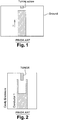
- the building block of cavity filters is a combline resonator, depicted in its basic form in Figure 1 consisting of a resonator post within a cavity.
- the resonator post resonates at a frequency at which the resonator post's height is one quarter-wavelength of the electric current, I , induced on the surface of the resonator post.
- I the electric current
- the typical practical realization of the resonator includes a tuning screw inserted from the top of the cavity toward the resonator's open (i.e. ungrounded) end.
- the tuning screw effectively balances the undesired effects caused by manufacturing tolerances. Put another way, the screw allows the resonator to be tune to the designed-for resonant frequency.
- the same mechanism can be utilized to retune the resonator.
- the range of tunability achievable this way in practice is only a few per cent, primarily limited by to the following consideration: the volume of space between the cavity top and the ungrounded end of the resonator is the region within the entire cavity where, at resonance, the electric field in the cavity is the strongest, meaning that this region is very susceptible to arcing.
- the tuning screw further reduces the size of the gap between the cavity top and the ungrounded end of the resonator, thus reducing the power-handling capability of the resonator. For reasons of power handling, the minimum size of the gap found in practical filters for wireless cellular-communication applications is about 1 mm.
- the change of resonant frequency achieved by tuning the resonator of Fig. 1 varies nonlinearly with the intrusion depth of the tuning screw into the cavity.
- the larger the intrusion depth the more rapidly the resonant frequency varies. Consequently, finely tuning the conventional resonator is difficult and time-consuming.
- a slightly larger tunability range is achieved by enlarging the surface area through which the tuning screw electromagnetically interacts with the resonator. As shown in Figure 2 , this may be achieved by hollowing the top part of the resonator and allowing the tuning screw to protrude slightly into the hollow.
- the present invention provides a resonator for a filter comprising a resonant chamber, the resonant chamber comprising a first wall, a second wall opposite the first wall, and side walls; the resonator also comprising:
- Preferred embodiments provide a high quality factor, good power handling, small size ('miniaturization'), and good tunability.
- Preferred embodiments simultaneously provides for (A) reduced physical dimensions of cavity filters and (B) an extended frequency-tunable range of cavity filters. Both qualities are valued in industrial applications.
- filters are typically the bulkiest and heaviest subsystems in mobile cellular base stations (rivalled only by power-amplifier heatsinks). Therefore filter miniaturization is always desirable.
- a typical envisioned application scenario includes a mobile cellular operator, who has a plan to transition its services to a different frequency band sometime in the future, procuring cavity filters for his base stations. If the operator purchases conventional filters, transitioning to the new frequency band eill require a second set of filters to be purchased. In contrast, the present invention eliminates the need to purchase the second set of filters, by providing for simple retuning of filters.
- manufacturers of mobile cellular base stations tend to stockpile cavity filters, rather than procure them in a build-to-order fashion.
- Filters according to preferred embodiments may be stock-piled and are readily retunable without the need to open the filter up.
- a preferred embodiment is a miniaturised coaxial resonator for a filter that simultaneously achieves size reduction, frequency tunability, and retention of high quality factors and high power handling.
- a part of the post lies within the first cylinder and the second cylinder.
- the first cylinder and the second cylinder are coaxial with each other and the resonator post.
- the resonator post is grounded on the first wall.
- the resonator post is grounded on the second wall.
- the resonator post is of adjustable length within the cavity for tuning.
- the resonator post is the shaft of a tuning screw.
- the first cylinder is an inner cylinder
- the second cylinder is an outer cylinder having an inner diameter wider than the outer diameter of the first cylinder.
- the main part of the first cylinder and the main part of the second cylinder are of least substantially the same diameter, and the end of the second cylinder distal from the first wall has an inner diameter wider than the outer diameter of the end of first cylinder distal from the second wall.
- the distal end of the first cylinder comprises an extending cylindrical wall thinner than the wall thickness of the main part of the first cylinder
- the distal end of the second cylinder comprises an extending cylindrical wall thinner than the wall thickness of the main part of the second cylinder.
- At least one of the first and second cylinders comprises a respective end wall for ease of mounting to the first wall or the second wall.
- the present invention also provides a radio frequency filter comprising at least one resonator as outlined above.
- the present invention also provides a method of radio frequency filtering comprising passing a radio frequency signal for filtering through a filter comprising a resonant chamber, the resonant chamber comprising a first wall, a second wall opposite the first wall, and side walls; the resonator also comprising:
- the inventors realised that in known cavity filters, modest frequency tunability is achievable by a tuning screw, positioned as shown in Figures 1 and 2 .
- Some other approaches involve incorporating an electronically controllable device inside the cavity of the filter.
- the electronically controllable device is usually a varactor diode (in which case the resulting filter has the same technical limitations as its Printed Circuit Board (PCB) counterpart) or a microelectromechanical system (MEMS).
- MEMS-based cavity filters are substantially similar to their counterparts having varactor diodes, with the exception that for the MEMS-based cavity filter, power handling capability is increased to some extent, while its tunable range is decreased due to the existence of stray capacitance between metallic contacts of the MEMS switch.
- the cavity resonator 4 includes a cavity 6 within a conductive enclosure 8. Extending into the cavity 6 from one wall 10 is a first tubular conductor 1 which has an open end 9. From that same wall 10, a tuner 12 also extends into the cavity 6. The tuner is a cylindrical metallic post, of adjustable length, which lies coaxially along the central longitudinal axis within the tubular conductor 1. From the wall 14 that is opposite the wall 10, a second tubular conductor 2 extends into the cavity 6. The second tubular conductor has an open end 11 . The second tubular conductor 2 has a diameter less than that of the first tubular conductor 1 but more than that of the tuner 12.
- the two tubular conductors 1, 2 and the tuner 12 are in close proximity with each other.
- the conductors 1, 2 and the tuner 12 are both electrically and mechanically connected to the respective wall 10,14 on which mounted.
- the two tubular conductors are hollow and of different widths (radii) so as to allow the second tubular conductor 2 to be inserted into the hollow space defined by the first tubular conductor 1.
- a portion of the second tubular conductor 2 lies within the first tubular conductor 1.
- the extent of the intrusion in other words the extent of overlap, determines the extent of electromagnetic coupling between the two conductors.
- the tuner 12 is provided for additional electromagnetic coupling with the second tubular conductor 2.
- the resonator 4 may be considered a three-element distributed resonator where the three elements are the two tubular conductors 1,2 and the tuner 12.
- This resonator may also be considered a miniaturised coaxial resonator.
- the tuner 12 is, in this example, a tuning screw which can be screwed in or out via a correspondingly threaded hole (not shown) in the first wall 10 of the enclosure 8 so as to adjust the length of the screw that resides within the cavity 6, in other words the extent of intrusion into the cavity 6.
- the electric current flow on the conductor 1 surface is such that the current density is highest at the area of contact with the wall 10 on which the conductor 1 is mounted.
- the wall 10 may be considered the ground plane of the conductor 1.
- the direction of propagation of the current is as shown in Figure 4 .
- This resultant magnetic field value is non-zero because the resonators, namely conductor 1, conductor 2 and tuner 12, are interacting with each other and the intensities of the resultant interacting magnetic fields in the inter-resonator regions are dependent on the separation between the respective resonators. In general, the smaller the separation is, the greater is the interacting magnetic field and, hence, the interaction between the respective resonators is greater. Since the level of interaction among the resonators determines the effective electrical length that the combined electric current depicted in Figure 4 needs to travel, it follows that closely coupled resonators of Figure 4 offer a reduction of frequency of operation compared to that of a single resonator in isolation.
- the resonator which is the tuner 12 is, in this example, in the form of a screw, whose intrusion into the cavity 8 can be variably adjusted. This means, there is frequency tunability as well as the reduction in the frequency of operation.
- miniaturized resonator arises from the rotational symmetry of the three resonators 1,2, 12 and the overall cavity resonator assembly 4. This is that as a direct consequence of the symmetries, at any point along the length of the individual resonators 1,2,12, the surface current density along the perimeter of each resonator is equally distributed. As a result, no surface current "hot spots" are created in this process of miniaturization, giving high power-handling capability.
- the second example is similar in structure to the first example except for having different dimensions, as follows: Table 2: Resonator dimensions Example 2 Resonator Example 1 Cavity (W x W x L) where W denotes width and L denotes length 2.3cmx2.3cmx3.0cm (15.87 cm 3 ) OuterDia1 which denotes the outer diameter of conductor 1 6.1 mm OuterDia2 which denotes the outer diameter of conductor 2 5.51 mm L1/ t1 where L1 is the length in the cavity of the conductor 1 and t1 is the thickness of the cylindrical wall of conductor 1 14.77 mm/0.45 mm L2/ t2 where L2 is the length in the cavity of the conductor 2 and t2 is the thickness of the cylindrical wall of conductor 2 19.08 mm/0.45 mm Lt/TunerDia where Lt is the length in the cavity of the tuner and TunerDia is the diameter of the tuner 27.54 mm/1.94 mm
- Table 3 shows the simulated performance of the two example resonators.
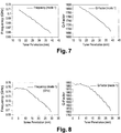
- Figure 7 (Left) and Figure 8 (Left) demonstrate the variation of resonant frequency as a function of the tuner penetration in the cavity for resonator example 1 and 2, respectively.
- Fig. 7 (Right) and Fig. 8 (Right) demonstrate the variation of the q-factor as a function of the tuner penetration in the cavity for resonator example 1 and 2, respectively.
- Table 3 Simulated performance of the two example resonators (CST Eigenmode solver) Resonator Electrical Length @700MHz (428.6 mm) Gap Size/Overlap Resonant frequency Q-Factor (Au/Au) 5.4x10 07 S/m Q/Vol (1/cm 3 )
- Example 1 ⁇ 33.6 deg 0.27/6.71 (mm) 709.6 MHz 1812 113.3
- Example 2 ⁇ 25.2 deg 0.14/4.31 (mm) 700.9 MHz 1809 114
- the power handling capability of the resonator 4 is strongly dependent on the overlap gap distance and length between the two main conductors, conductor 1 and conductor 2. It follows that these dimensions determine both the power handling capacity of the resonator 4, and the amount of miniaturization (size as compared to a corresponding known resonator) . Thus, there is a trade-off to consider: the more we miniaturize, the less the handling capacity is going to be. It has been shown that changes to size can be made, for example to the overlap gap distance and length, without greatly affecting electrical performance. See for example Table 2, where the two examples have similar electrical performance, i.e. resonant frequency and Q-factor.
- Figure 9 shows an alternative example in which the cylindrical conductors 1',2' mounted on opposite walls 10',14' are equal in radius save at their open ends 1a', 2a' where the extended rim portion 2b' of second conductor 2' fits in a no-contacting way within the extended rim portion 1b' of first conductor 1'.
- FIG 10 shows another example in which the cylindrical conductors 1" and 2" include respective end wall portions 1c, 2c for ease of mounting to cavity end walls 10", 14".
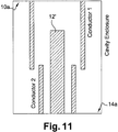
- FIG 11 shows an example in which the tuner post12' is mounted on the wall 14a on which the smaller radius cylindrical conductor 2 instead of on the wall 10a on which the larger radius cylindrical conductor 1 is mounted.
- program storage devices e.g., digital data storage media, which are machine or computer readable and encode machine-executable or computer-executable programs of instructions, wherein said instructions perform some or all of the steps of said above-described methods.
- the program storage devices may be, e.g., digital memories, magnetic storage media such as a magnetic disks and magnetic tapes, hard drives, or optically readable digital data storage media.
- Some embodiments involve computers programmed to perform said steps of the above-described methods.
Landscapes
- Control Of Motors That Do Not Use Commutators (AREA)
Priority Applications (3)
| Application Number | Priority Date | Filing Date | Title |
|---|---|---|---|
| EP15305879.7A EP3104452A1 (fr) | 2015-06-10 | 2015-06-10 | Résonateur, filtre hyperfréquence et procédé de filtrage de fréquences radio |
| EP15306171.8A EP3104453A1 (fr) | 2015-06-10 | 2015-07-17 | Ensemble de resonateur et filtre |
| PCT/EP2016/063058 WO2016198466A1 (fr) | 2015-06-10 | 2016-06-08 | Ensemble résonateur, et filtre |
Applications Claiming Priority (1)
| Application Number | Priority Date | Filing Date | Title |
|---|---|---|---|
| EP15305879.7A EP3104452A1 (fr) | 2015-06-10 | 2015-06-10 | Résonateur, filtre hyperfréquence et procédé de filtrage de fréquences radio |
Publications (1)
| Publication Number | Publication Date |
|---|---|
| EP3104452A1 true EP3104452A1 (fr) | 2016-12-14 |
Family
ID=53404469
Family Applications (2)
| Application Number | Title | Priority Date | Filing Date |
|---|---|---|---|
| EP15305879.7A Withdrawn EP3104452A1 (fr) | 2015-06-10 | 2015-06-10 | Résonateur, filtre hyperfréquence et procédé de filtrage de fréquences radio |
| EP15306171.8A Withdrawn EP3104453A1 (fr) | 2015-06-10 | 2015-07-17 | Ensemble de resonateur et filtre |
Family Applications After (1)
| Application Number | Title | Priority Date | Filing Date |
|---|---|---|---|
| EP15306171.8A Withdrawn EP3104453A1 (fr) | 2015-06-10 | 2015-07-17 | Ensemble de resonateur et filtre |
Country Status (2)
| Country | Link |
|---|---|
| EP (2) | EP3104452A1 (fr) |
| WO (1) | WO2016198466A1 (fr) |
Cited By (1)
| Publication number | Priority date | Publication date | Assignee | Title |
|---|---|---|---|---|
| CN112448114A (zh) * | 2019-08-29 | 2021-03-05 | 诺基亚技术有限公司 | 谐振器 |
Families Citing this family (7)
| Publication number | Priority date | Publication date | Assignee | Title |
|---|---|---|---|---|
| EP3547440A1 (fr) * | 2018-03-27 | 2019-10-02 | Nokia Solutions and Networks Oy | Résonateur pour signaux de fréquence radio |
| JPWO2020090547A1 (ja) * | 2018-10-30 | 2021-09-02 | 京セラ株式会社 | 共振器、フィルタおよび通信装置 |
| CN111180841A (zh) * | 2018-11-12 | 2020-05-19 | 罗森伯格技术(昆山)有限公司 | 一种滤波器及通信设备 |
| EP3660977B1 (fr) * | 2018-11-30 | 2023-12-13 | Nokia Solutions and Networks Oy | Résonateur pour signaux de fréquence radio |
| WO2020158793A1 (fr) * | 2019-01-29 | 2020-08-06 | 京セラ株式会社 | Résonateur, filtre et dispositif de communication |
| CN113495373B (zh) * | 2020-03-20 | 2024-11-08 | 中移(上海)信息通信科技有限公司 | 一种可调谐吸收器 |
| CN115800924B (zh) * | 2022-11-22 | 2023-09-12 | 无锡国弛强包装机械有限公司 | 一种高周波谐振发生装置 |
Citations (6)
| Publication number | Priority date | Publication date | Assignee | Title |
|---|---|---|---|---|
| US2181901A (en) * | 1937-01-04 | 1939-12-05 | Rca Corp | Resonant line |
| US3448412A (en) * | 1967-04-21 | 1969-06-03 | Us Navy | Miniaturized tunable resonator comprising intermeshing concentric tubular members |
| US5867076A (en) * | 1992-07-24 | 1999-02-02 | Murata Manufacturing Co., Ltd. | Dielectric resonator and dielectric resonant component having stepped portion and non-conductive inner portion |
| JP2002076709A (ja) * | 2000-09-05 | 2002-03-15 | Shimada Phys & Chem Ind Co Ltd | 高周波フィルタ及び半同軸共振器 |
| EP2533356A1 (fr) * | 2011-06-08 | 2012-12-12 | Powerwave Finland Oy | Résonateur réglable |
| US20140347148A1 (en) * | 2013-05-27 | 2014-11-27 | Jorge A. Ruiz-Cruz | Method of operation and construction of filters and multiplexers using multi-conductor multi-dielectric combline resonators |
Family Cites Families (2)
| Publication number | Priority date | Publication date | Assignee | Title |
|---|---|---|---|---|
| CH236501A (de) * | 1943-02-18 | 1945-02-15 | Patelhold Patentverwertung | Hohlraumresonator mit veränderbarer Eigenfrequenz. |
| FR2658955B1 (fr) * | 1990-02-26 | 1992-04-30 | Commissariat Energie Atomique | Resonateur coaxial a capacite d'accord repartie. |
-
2015
- 2015-06-10 EP EP15305879.7A patent/EP3104452A1/fr not_active Withdrawn
- 2015-07-17 EP EP15306171.8A patent/EP3104453A1/fr not_active Withdrawn
-
2016
- 2016-06-08 WO PCT/EP2016/063058 patent/WO2016198466A1/fr not_active Ceased
Patent Citations (6)
| Publication number | Priority date | Publication date | Assignee | Title |
|---|---|---|---|---|
| US2181901A (en) * | 1937-01-04 | 1939-12-05 | Rca Corp | Resonant line |
| US3448412A (en) * | 1967-04-21 | 1969-06-03 | Us Navy | Miniaturized tunable resonator comprising intermeshing concentric tubular members |
| US5867076A (en) * | 1992-07-24 | 1999-02-02 | Murata Manufacturing Co., Ltd. | Dielectric resonator and dielectric resonant component having stepped portion and non-conductive inner portion |
| JP2002076709A (ja) * | 2000-09-05 | 2002-03-15 | Shimada Phys & Chem Ind Co Ltd | 高周波フィルタ及び半同軸共振器 |
| EP2533356A1 (fr) * | 2011-06-08 | 2012-12-12 | Powerwave Finland Oy | Résonateur réglable |
| US20140347148A1 (en) * | 2013-05-27 | 2014-11-27 | Jorge A. Ruiz-Cruz | Method of operation and construction of filters and multiplexers using multi-conductor multi-dielectric combline resonators |
Non-Patent Citations (2)
| Title |
|---|
| J.S. HONG; M.J. LANCASTER: "Microstrip Filters for RF/Microwave Applications", 2001, JOHN WILEY & SONS |
| MUSONDA EVARISTO ET AL: "Microwave Bandpass Filters Using Re-Entrant Resonators", IEEE TRANSACTIONS ON MICROWAVE THEORY AND TECHNIQUES, IEEE SERVICE CENTER, PISCATAWAY, NJ, US, vol. 63, no. 3, 1 March 2015 (2015-03-01), pages 954 - 964, XP011574138, ISSN: 0018-9480, [retrieved on 20150303], DOI: 10.1109/TMTT.2015.2389216 * |
Cited By (1)
| Publication number | Priority date | Publication date | Assignee | Title |
|---|---|---|---|---|
| CN112448114A (zh) * | 2019-08-29 | 2021-03-05 | 诺基亚技术有限公司 | 谐振器 |
Also Published As
| Publication number | Publication date |
|---|---|
| WO2016198466A1 (fr) | 2016-12-15 |
| EP3104453A1 (fr) | 2016-12-14 |
Similar Documents
| Publication | Publication Date | Title |
|---|---|---|
| EP3104452A1 (fr) | Résonateur, filtre hyperfréquence et procédé de filtrage de fréquences radio | |
| US6686815B1 (en) | Microwave filter | |
| EP1742354B1 (fr) | Filtre passe-bande multicouche | |
| US9236846B2 (en) | Tunable bandpass filter device and method | |
| US7310031B2 (en) | Dielectric resonators and circuits made therefrom | |
| US6621381B1 (en) | TEM-mode dielectric resonator and bandpass filter using the resonator | |
| US7183881B2 (en) | Cross-coupled dielectric resonator circuit | |
| Boutejdar | Design of 5 GHz‐compact reconfigurable DGS‐bandpass filter using varactor‐diode device and coupling matrix technique | |
| US10033084B2 (en) | Operation frequency band customizable and frequency tunable filters with EBG substrates | |
| EP2814112A1 (fr) | Ensemble de résonance | |
| CN1983711A (zh) | 电子可调谐介质谐振器电路 | |
| KR20160117574A (ko) | 공진기 어셈블리 및 필터 | |
| EP3416232B1 (fr) | Dispositif électronique à module de filtre par fréquence radio (rf) avec résonateurs coaxiaux empilés et procédés associés | |
| Kumar et al. | Design of improved quadruple-mode bandpass filter using cavity resonator for 5G mid-band applications | |
| JP2000151210A (ja) | 誘電体フィルタ | |
| KR102686326B1 (ko) | 세라믹 유전체를 이용하여 소형화 및 고출력이 가능한 대역저지필터 | |
| Doumanis | A technique to suppress harmonic outputs in coaxial cavity filters at the excitation port | |
| EP3012901B1 (fr) | Résonateur, filtre de fréquence radio et procédé de filtrage | |
| Bakr et al. | Dual-mode dual-band conductor-loaded dielectric resonator filters | |
| EP3324480B1 (fr) | Résonateur, résonateur assemblée et filtre | |
| Zhang et al. | Design of miniaturized bandpass filter using modified coaxial cavity resonator | |
| KR100368035B1 (ko) | 다단 결합이 용이한 소형 단위 세라믹 공진기 | |
| EP2814111B1 (fr) | Ensemble de résonance | |
| US9455484B2 (en) | Wideband electronically tunable cavity filters | |
| Wattikornsirikul et al. | High-selectivity Dual-band Bandpass Filter By Utilizing Asymmetrical Stepped-impedance Resonator |
Legal Events
| Date | Code | Title | Description |
|---|---|---|---|
| PUAI | Public reference made under article 153(3) epc to a published international application that has entered the european phase |
Free format text: ORIGINAL CODE: 0009012 |
|
| AK | Designated contracting states |
Kind code of ref document: A1 Designated state(s): AL AT BE BG CH CY CZ DE DK EE ES FI FR GB GR HR HU IE IS IT LI LT LU LV MC MK MT NL NO PL PT RO RS SE SI SK SM TR |
|
| AX | Request for extension of the european patent |
Extension state: BA ME |
|
| 17P | Request for examination filed |
Effective date: 20170614 |
|
| RBV | Designated contracting states (corrected) |
Designated state(s): AL AT BE BG CH CY CZ DE DK EE ES FI FR GB GR HR HU IE IS IT LI LT LU LV MC MK MT NL NO PL PT RO RS SE SI SK SM TR |
|
| RAP1 | Party data changed (applicant data changed or rights of an application transferred) |
Owner name: ALCATEL LUCENT |
|
| RAP1 | Party data changed (applicant data changed or rights of an application transferred) |
Owner name: PROVENANCE ASSET GROUP LLC |
|
| STAA | Information on the status of an ep patent application or granted ep patent |
Free format text: STATUS: THE APPLICATION IS DEEMED TO BE WITHDRAWN |
|
| 18D | Application deemed to be withdrawn |
Effective date: 20190103 |