EP2814408B1 - Medizinisches instrument - Google Patents
Medizinisches instrument Download PDFInfo
- Publication number
- EP2814408B1 EP2814408B1 EP13706158.6A EP13706158A EP2814408B1 EP 2814408 B1 EP2814408 B1 EP 2814408B1 EP 13706158 A EP13706158 A EP 13706158A EP 2814408 B1 EP2814408 B1 EP 2814408B1
- Authority
- EP
- European Patent Office
- Prior art keywords
- sleeve
- active elements
- medical instrument
- tool
- recesses
- Prior art date
- Legal status (The legal status is an assumption and is not a legal conclusion. Google has not performed a legal analysis and makes no representation as to the accuracy of the status listed.)
- Active
Links
Images

Classifications
-
- A—HUMAN NECESSITIES
- A61—MEDICAL OR VETERINARY SCIENCE; HYGIENE
- A61B—DIAGNOSIS; SURGERY; IDENTIFICATION
- A61B17/00—Surgical instruments, devices or methods
- A61B17/32—Surgical cutting instruments
- A61B17/3201—Scissors
-
- A—HUMAN NECESSITIES
- A61—MEDICAL OR VETERINARY SCIENCE; HYGIENE
- A61B—DIAGNOSIS; SURGERY; IDENTIFICATION
- A61B17/00—Surgical instruments, devices or methods
- A61B17/32—Surgical cutting instruments
- A61B17/320016—Endoscopic cutting instruments, e.g. arthroscopes, resectoscopes
-
- A—HUMAN NECESSITIES
- A61—MEDICAL OR VETERINARY SCIENCE; HYGIENE
- A61F—FILTERS IMPLANTABLE INTO BLOOD VESSELS; PROSTHESES; DEVICES PROVIDING PATENCY TO, OR PREVENTING COLLAPSING OF, TUBULAR STRUCTURES OF THE BODY, e.g. STENTS; ORTHOPAEDIC, NURSING OR CONTRACEPTIVE DEVICES; FOMENTATION; TREATMENT OR PROTECTION OF EYES OR EARS; BANDAGES, DRESSINGS OR ABSORBENT PADS; FIRST-AID KITS
- A61F9/00—Methods or devices for treatment of the eyes; Devices for putting in contact-lenses; Devices to correct squinting; Apparatus to guide the blind; Protective devices for the eyes, carried on the body or in the hand
- A61F9/007—Methods or devices for eye surgery
- A61F9/00736—Instruments for removal of intra-ocular material or intra-ocular injection, e.g. cataract instruments
-
- A—HUMAN NECESSITIES
- A61—MEDICAL OR VETERINARY SCIENCE; HYGIENE
- A61B—DIAGNOSIS; SURGERY; IDENTIFICATION
- A61B17/00—Surgical instruments, devices or methods
- A61B17/28—Surgical forceps
- A61B17/29—Forceps for use in minimally invasive surgery
- A61B2017/2926—Details of heads or jaws
- A61B2017/2932—Transmission of forces to jaw members
- A61B2017/2933—Transmission of forces to jaw members camming or guiding means
-
- A—HUMAN NECESSITIES
- A61—MEDICAL OR VETERINARY SCIENCE; HYGIENE
- A61B—DIAGNOSIS; SURGERY; IDENTIFICATION
- A61B17/00—Surgical instruments, devices or methods
- A61B17/28—Surgical forceps
- A61B17/29—Forceps for use in minimally invasive surgery
- A61B2017/2926—Details of heads or jaws
- A61B2017/2932—Transmission of forces to jaw members
- A61B2017/2933—Transmission of forces to jaw members camming or guiding means
- A61B2017/2937—Transmission of forces to jaw members camming or guiding means with flexible part
-
- A—HUMAN NECESSITIES
- A61—MEDICAL OR VETERINARY SCIENCE; HYGIENE
- A61B—DIAGNOSIS; SURGERY; IDENTIFICATION
- A61B17/00—Surgical instruments, devices or methods
- A61B17/30—Surgical pincettes, i.e. surgical tweezers without pivotal connections
- A61B2017/305—Tweezer like handles with tubular extensions, inner slidable actuating members and distal tools, e.g. microsurgical instruments
Definitions
- the invention relates to a medical instrument, in particular scissors, forceps or the like., For use in ophthalmology.
- the instruments in question must have minimal dimensions, so that it is very filigree and expensive to manufacture instruments. As a result, for example, when cutting through the counterpressure exerted by the tissue, the blades of the blades no longer slide against one another but are spread apart from one another.
- DE 10 2009 033015 A1 discloses a medical instrument for use in ophthalmology, comprising a tool having a range of action and an operating area and a sleeve, wherein the active area comprises two mutually movable, cooperating active elements, wherein the sleeve surrounds the tool, at least in the operating area completely or partially, wherein the active elements by moving the sleeve relative to the tool against each other are movable.
- the present invention is therefore based on the object, a medical instrument of the type mentioned in such a way and further develop that with simple design means a safe and precise function of the instrument is guaranteed.
- a medical instrument is specified, with a range of action and an actuating region having tool and a sleeve, wherein the active region has two mutually movable, cooperating active elements, wherein the sleeve surrounds the tool at least in the operating area completely or partially, wherein the active elements by moving the Sleeve relative to the tool are movable against each other and wherein on the sleeve recesses for guiding the active elements are formed.
- the underlying object can be achieved by a clever design of the tool and the sleeve surrounding the tool.
- the tool comprises an effective range and an operating range, wherein the effective range is two against each other having movable, cooperating active elements.
- the sleeve surrounds the tool at least in the operating area wholly or partially, wherein the active elements are movable relative to each other by moving the sleeve relative to the tool.
- the precise function of the medical instrument is ensured in a surprisingly simple manner, if recesses for guiding the active elements are formed on the sleeve.
- the active elements are exactly guided in the recesses. Unintentional movements of the active elements are inhibited by the recesses. For the surgeon is therefore always ensured that the instrument acts precisely at the point he wants. Due to the simple construction, the production of the medical hand-held device according to the invention is inexpensive and of little effort.
- the transition between effective range and operating range is fluid.
- the sleeve can also - at least partially - surround the tool in the effective range.
- the decisive factor is that the sleeve cooperates with the tool in such a way that the active elements are movable relative to one another by displacement of the sleeve relative to the tool.
- the sleeve can surround the tool in the actuation area and / or in the effective area and / or in the transition between actuation area and effective area.
- the sleeve has in the region of their recesses bevels on which slide the active elements.
- the bevels can be formed in the inner region of the sleeve-for example as a chamfer.
- the bevels simplify the insertion of the tool into the sleeve.
- the active elements slide better on the slopes, so that the movement of the active elements is liquid or more uniformly executable.
- the recesses are formed such that the active elements are guided in the open and closed state of the recesses. This construction ensures that the active elements, regardless of their positioning relative to the sleeve, are always guided in the recesses. Unintentional evasive movements of the active elements, for example when cutting or gripping harder tissue, are always inhibited by the recesses.
- the sleeve may have bevels at its distal end. Due to the beveled distal end of the sleeve this does not obstruct the surgeon's view of the site of intervention.
- a linear or curved sliding surface is formed on the active elements, with which the active elements slide on the recesses of the sleeve.
- a different course of movement of the active elements is achieved.
- a different speed with which the active elements move against each other is achieved.
- the sliding surfaces may for example be shaped such that the active elements move only slightly against each other with a large displacement of the sleeve relative to the instrument.
- the sliding surfaces can thereby be adapted to different surgical techniques or to preferences of the surgeon. The surgeon can thus select an instrument whose active elements for the respective intervention have the optimal movement behavior.
- a stop can be formed on at least one active element.
- the stopper it is possible to inhibit the movement of the active elements against each other from a certain point.
- the active elements are designed as blades of a pair of scissors.
- the blades are moved against each other so that the blades perform a cutting motion. Since the blades are guided in the recesses of the sleeve, a spreading apart of the blade blades when cutting harder tissue is largely prevented.
- the recesses may be dimensioned such that the blades are pressed against each other with their blade blades. The blades are thereby held on pretension. This design is another measure to avoid spreading the blade blades. Another advantage is that the blades are always held in a precise position. Furthermore, it is conceivable that the tool is designed in the form of a shears.
- the active elements can be designed as gripping jaws of a pair of pliers. Due to the relative displacement between the sleeve and the tool, the jaws are movable relative to each other. The precise gripping of tissue is ensured by the guidance of the jaws in the recesses of the sleeve, even with greater back pressure.
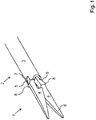
- Fig. 1 shows a schematic view of an embodiment of a medical instrument according to the invention.
- the instrument is designed as a pair of scissors for use in ophthalmological surgery.
- the instrument has a tool.
- the tool comprises an effective region 1 and an actuating region 2, wherein the actuating region 2 is surrounded by a sleeve 3.
- Fig.1 Therefore, only the effective range 1 is visible, the actuating portion 2 is disposed within the sleeve 3.
- the active region 1 has two mutually movable active elements 4.
- Out Fig.1 clearly shows that the transition between operating range 1 and effective range 2 is not clearly definable but rather fluid.
- the active elements 4 are designed as blades of a pair of scissors.
- the active elements 4 can also be designed as gripping jaws of a pair of pliers, so that the medical instrument serves for gripping tissue.
- Fig. 1 the tool is shown in the open state, ie the blades 4 of the scissors are in the open position.
- the blades 4 may be biased towards their open position or against their open position.
- the bias can be done for example via a spring or any other construction.
- the tool is designed in accordance with a shearing machine, so that the blades 4 are biased in the direction of their open position due to their residual stress.
- the blades 4 slide with their sliding surfaces 5 along the inside of the sleeve 3 along, whereby the blades 4 are moved against each other. If the sleeve 3 and the tool are displaced relative to each other, then the blades 4 perform a cutting movement.
- the blades 4 As the blades 4 move against each other, they slide with the blade blades 6 on each other. In order to avoid spreading the blade blades 6, as may occur, for example, when cutting harder tissue, the blades 4 are guided in recesses 7 of the sleeve 3.
- the recesses 7 guide the blades 4 regardless of the position of the sleeve 3. By the recesses 7 prevents the blades 4 are spread apart from each other with strong back pressure.
- the recesses 7 are formed such that the blade blades 6 are pressed against each other at least slightly. By the pressure exerted by the blade blades 6 on each other, a spreading apart of the blade blades 6 during cutting is avoided.
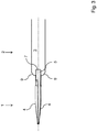
- Fig. 2 is the embodiment of an instrument according to the invention Fig. 1 shown in a plan view.
- Fig. 2 clearly shows that the blades 4 each have a stop 8.
- the stops 8 serve to limit the displacement between the sleeve 3 and tool. In this way can be defined exactly how far the blades 4 can be moved against each other. If the active elements 4 are designed as gripping jaws, it is possible to adjust via the stop 8 or the stops 8 as to whether the gripping jaws touch in the closed position.
- Fig. 2 recognizable that the sliding surfaces 5 are curved.
- the movement of the blades 4 is defined by the curvature of the sliding surfaces 5 during a displacement between the sleeve 3 and the tool.
- the blades 4 move faster or slower in a displacement of the sleeve 3 relative to the tool.
- Fig. 3 shows the embodiment Fig. 1 in a side view. It can be clearly seen that the sleeve 3 has bevels 9 at its distal end. Due to the chamfered design of the distal end of the sleeve 3, this does not obstruct the surgeon's view of the intervention field. In order to avoid repetition, reference should be made to the description of the Fig. 1 and 2 directed.
Landscapes
- Health & Medical Sciences (AREA)
- Surgery (AREA)
- Life Sciences & Earth Sciences (AREA)
- Public Health (AREA)
- Animal Behavior & Ethology (AREA)
- Engineering & Computer Science (AREA)
- Biomedical Technology (AREA)
- Heart & Thoracic Surgery (AREA)
- Veterinary Medicine (AREA)
- General Health & Medical Sciences (AREA)
- Nuclear Medicine, Radiotherapy & Molecular Imaging (AREA)
- Molecular Biology (AREA)
- Medical Informatics (AREA)
- Ophthalmology & Optometry (AREA)
- Orthopedic Medicine & Surgery (AREA)
- Vascular Medicine (AREA)
- Pathology (AREA)
- Surgical Instruments (AREA)
Description
- Die Erfindung betrifft ein medizinisches Instrument, insbesondere Schere, Zange oder dgl., zur Anwendung in der Ophthalmologie.
- Medizinische Instrumente der in Rede stehenden Art sind seit Jahren aus der Praxis bekannt. Insbesondere bei chirurgischen Eingriffen muss Gewebe beispielsweise zerschnitten, abgeklemmt, gehalten oder weggezogen werden. Des Weiteren muss der Operateur auch andere Materialien, beispielsweise, Nahtmaterial, Tupfer, Nadeln, Verbänden, Tamponaden etc. greifen und/oder zertrennen. Dazu sind Scheren und Zangen in den unterschiedlichsten Ausführungsformen vorbekannt. Bei Scheren zur Anwendung in der ophthalmologischen Chirurgie werden die Klingen durch eine relativ zu den Klingen verschiebbare Hülse aufeinander zu bzw. voneinander weg bewegt. Dazu ist der Körper der Schere von der Hülse umgeben, wobei die Klingen zumindest teilweise aus der Hülse herausragen. Ähnliche Konstruktionen existieren, um Material zu greifen oder wegzuziehen, wobei bei diesen Instrumenten Greifbacken einer Zange durch eine verschiebbare Hülse gegeneinander bewegbar sind.
- An dieser Stelle sei angemerkt, dass im Folgenden zur Vereinfachung lediglich von Gewebe die Rede ist. Darunter sind sowohl die voranstehend genannten Materialien als auch Gewebe, insbesondere Gewebe des menschlichen oder tierischen Auges, zu verstehen.
- Die in Rede stehenden Instrumente müssen minimale Abmessungen aufweisen, so dass es sich um sehr filigrane und in der Herstellung aufwendige Instrumente handelt. Dies führt dazu, dass beispielsweise beim Schneiden durch den vom Gewebe ausgeübten Gegendruck die Klingenblätter der Klingen nicht mehr aneinander gleiten sondern voneinander abgespreizt werden.
- Insbesondere beim Zerschneiden von härterem Gewebe wird dieses daher gequetscht, was zu erheblichen, mitunter irreparablen Verletzungen des Auges führen kann. Die exakte Schnittführung des Instruments ist nicht mehr gewährleistet. Des Weiteren wird das Gewebe während des Schnitts derart verschoben, dass die Zertrennung des Gewebes nicht mehr an dem von dem Operateur gewählten Punkt erfolgt.
- Beim Abspreizen der Greifbacken ist problematisch, dass nicht genug Druck auf das Gewebe ausgeübt wird, um dieses sicher zu fassen. Beispielsweise beim Nähen von Gewebe muss der Operateur jedoch mitunter größeren Druck auf das Nahtmaterial ausüben, um einen chirurgischen Knoten zu knüpfen. Die aus der Praxis bekannten Instrumente eignen sich hierfür nicht.
-
DE 10 2009 033015 A1 offenbart ein medizinisches Instrument zur Anwendung in der Ophthalmologie, mit einem einen Wirkbereich und einen Betätigungsbereich aufweisenden Werkzeug und einer Hülse, wobei der Wirkbereich zwei gegeneinander bewegbare, zusammenwirkende Wirkelemente aufweist, wobei die Hülse das Werkzeug zumindest im Betätigungsbereich ganz oder teilweise umgibt, wobei die Wirkelemente durch Verschieben der Hülse relativ zum Werkzeug gegeneinander bewegbar sind. - Ein präzises und sicheres Arbeiten ist mit den aus der Praxis bekannten Instrumenten daher nur bedingt möglich. Insbesondere die sichere Handhabung von härterem Gewebe, das einen höheren Gegendruck auf die Schneiden bzw. Greifbacken ausübt, ist mit den bekannten Instrumenten nicht möglich.
- Der vorliegenden Erfindung liegt daher die Aufgabe zugrunde, ein medizinisches Instrument der eingangs genannten Art derart auszugestalten und weiterzubilden, dass mit konstruktiv einfachen Mitteln eine sichere und präzise Funktion des Instruments gewährleistet ist.
- Erfindungsgemäß wird die voranstehende Aufgabe durch die Merkmale des Patentanspruchs 1 gelöst. Damit ist ein medizinisches Instrument angegeben, mit einem einen Wirkbereich und einen Betätigungsbereich aufweisenden Werkzeug und einer Hülse, wobei der Wirkbereich zwei gegeneinander bewegbare, zusammenwirkende Wirkelemente aufweist, wobei die Hülse das Werkzeug zumindest im Betätigungsbereich ganz oder teilweise umgibt, wobei die Wirkelemente durch Verschieben der Hülse relativ zum Werkzeug gegeneinander bewegbar sind und wobei an der Hülse Ausnehmungen zur Führung der Wirkelemente ausgebildet sind.
- In erfindungsgemäßer Weise ist erkannt worden, dass die zugrundeliegende Aufgabe durch eine geschickte Ausgestaltung des Werkzeugs und der das Werkzeug umgebenden Hülse gelöst werden kann. Dazu umfasst das Werkzeug einen Wirkbereich und einen Betätigungsbereich, wobei der Wirkbereich zwei gegeneinander bewegbare, zusammenwirkende Wirkelemente aufweist. Die Hülse umgibt das Werkzeug zumindest im Betätigungsbereich ganz oder teilweise, wobei die Wirkelemente durch ein Verschieben der Hülse relativ zum Werkzeug gegeneinander bewegbar sind. In weiter erfindungsgemäßer Weise ist erkannt worden, dass die präzise Funktion des medizinischen Instruments auf verblüffend einfache Weise gewährleistet ist, wenn an der Hülse Ausnehmungen zur Führung der Wirkelemente ausgebildet sind. Ein Abspreizen der Wirkelemente bei erhöhtem Gegendruck, beispielsweise während des Zertrennens oder Greifens von härterem Gewebe, wird dadurch effektiv vermieden. Die Wirkelemente sind in den Ausnehmungen exakt geführt. Ungewollte Bewegungen der Wirkelemente sind durch die Ausnehmungen gehemmt. Für den Operateur ist daher stets gewährleistet, dass das Instrument präzise an dem von ihm gewünschten Punkt wirkt. Aufgrund der einfachen Konstruktion ist die Herstellung des erfindungsgemäßen medizinischen Handgeräts preiswert und von geringem Aufwand.
- Es sei ausdrücklich darauf hingewiesen, dass der Übergang zwischen Wirkbereich und Betätigungsbereich fließend ist. Die Hülse kann das Werkzeug auch - zumindest teilweise - im Wirkbereich umgeben. Maßgeblich ist, dass die Hülse derart mit dem Werkzeug zusammenwirkt, dass die Wirkelemente durch eine Verschiebung der Hülse relativ zu dem Werkzeug gegeneinander bewegbar sind. Dabei kann die Hülse das Werkzeug im Betätigungsbereich und/oder im Wirkbereich und/oder im Übergang zwischen Betätigungsbereich und Wirkbereich umgeben.
- Um eine möglichst gleichmäßige Bewegung der Wirkelemente gegeneinander zu gewährleisten, weist die Hülse im Bereich ihrer Ausnehmungen Schrägen auf, auf denen die Wirkelemente gleiten. Die Schrägen können im inneren Bereich der Hülse - beispielsweise als Fase - ausgebildet sein. Während der Herstellung des Instruments vereinfachen die Schrägen die Einführung des Werkzeugs in die Hülse. Des Weiteren gleiten die Wirkelemente besser auf den Schrägen, so dass die Bewegung der Wirkelemente flüssiger bzw. gleichmäßiger ausführbar ist.
- In besonders vorteilhafter Weise sind die Ausnehmungen derart ausgebildet, dass die Wirkelemente im geöffneten und im geschlossenen Zustand von den Ausnehmungen geführt sind. Durch diese Konstruktion ist gewährleistet, dass die Wirkelemente unabhängig von ihrer Positionierung relativ zur Hülse, stets in den Ausnehmungen geführt sind. Ungewollte Ausweichbewegungen der Wirkelemente, beispielsweise beim Schneiden oder Greifen von härterem Gewebe, sind durch die Ausnehmungen stets gehemmt.
- Zur weiteren Optimierung der Handhabung für den Operateur kann die Hülse an ihrem distalen Ende Abschrägungen aufweisen. Aufgrund des abgeschrägten distalen Endes der Hülse versperrt diese dem Operateur nicht die Sicht auf die Eingriffsstelle.
- In vorteilhafter Weise ist an den Wirkelementen jeweils eine linear oder kurvenförmig verlaufende Gleitfläche ausgebildet, mit der die Wirkelemente auf den Ausnehmungen der Hülse gleiten. Je nach Ausgestaltung der Gleitflächen wird ein anderer Bewegungsverlauf der Wirkelemente erreicht. Bei gleicher relativer Geschwindigkeit zwischen Hülse und Werkzeug ergibt sich in Abhängigkeit von der Ausbildung der Gleitflächen eine unterschiedliche Geschwindigkeit, mit der sich die Wirkelemente gegeneinander bewegen. Über die Ausgestaltung der Gleitflächen - linear oder kurvenförmig - kann auch Einfluss darauf genommen werden, wie weit sich die Wirkelemente bei einer relativen Verschiebung der Hülse zu dem Werkzeug gegeneinander bewegen. Die Gleitflächen können beispielsweise derart ausgeformt sein, dass sich die Wirkelemente bei einer großen Verschiebung der Hülse relativ zu dem Instrument nur geringfügig gegeneinander bewegen. Die Gleitflächen können dadurch auf verschiedene Operationstechniken oder auf Vorlieben des Operateurs angepasst sein. Der Operateur kann somit ein Instrument auswählen, dessen Wirkelemente für den jeweiligen Eingriff das optimale Bewegungsverhalten aufweisen.
- Um die Verschiebung zwischen Hülse und Instrument zu begrenzen, kann an mindestens einem Wirkelement ein Anschlag ausgebildet sein. Durch den Anschlag ist es möglich, die Bewegung der Wirkelemente gegeneinander ab einem bestimmten Punkt zu hemmen.
- In vorteilhafter Weise sind die Wirkelemente als Klingen einer Schere ausgebildet. Durch die Verschiebung der Hülse relativ zum Werkzeug werden die Klingen gegeneinander bewegt, so dass die Klingen eine Schneidbewegung ausführen. Da die Klingen in den Ausnehmungen der Hülse geführt sind, wird ein Abspreizen der Klingenblätter beim Schneiden von härterem Gewebe weitgehend verhindert.
- In besonders vorteilhafter Weise können die Ausnehmungen derart dimensioniert sein, dass die Klingen mit ihren Klingenblättern gegeneinander gedrückt sind. Die Klingen werden dadurch auf Vorspannung gehalten. Diese Konstruktion stellt eine weitere Maßnahme zur Vermeidung eines Abspreizens der Klingenblätter dar. Ein weiterer Vorteil liegt darin, dass die Klingen stets in einer präzisen Position gehalten sind. Des Weiteren ist denkbar, dass das Werkzeug in Form einer Bügelschere ausgeführt ist.
- In weiter vorteilhafter Weise können die Wirkelemente als Greifbacken einer Zange ausgeführt sein. Durch die relative Verschiebung zwischen Hülse und Werkzeug sind die Greifbacken gegeneinander bewegbar. Das präzise Greifen von Gewebe ist durch die Führung der Greifbacken in den Ausnehmungen der Hülse auch bei größerem Gegendruck gewährleistet.
- Es gibt nun verschiedene Möglichkeiten, die Lehre der vorliegenden Erfindung in vorteilhafter Weise auszugestalten und weiterzubilden. Dazu ist einerseits auf die dem Patentanspruch 1 nachgeordneten Patentansprüche und andererseits auf die nachfolgende Erläuterung eines bevorzugten Ausführungsbeispiels der Erfindung anhand der Zeichnung zu verweisen. In Verbindung mit der Erläuterung des bevorzugten Ausführungsbeispiels der Erfindung anhand der Zeichnung werden auch im Allgemeinen bevorzugte Ausgestaltungen und Weiterbildungen der Lehre erläutert. In der Zeichnung zeigen
- Fig. 1
- in einer schematische Darstellung ein Ausführungsbeispiel eines erfindungsgemäßen medizinischen Instruments in einer perspektivischen Ansicht,
- Fig. 2
- in einer schematischen Darstellung das medizinische Instrument aus
Fig. 1 in einer Draufsicht und - Fig. 3
- in einer schematischen Darstellung das erfindungsgemäße medizinische Instrument aus
Fig. 1 in einer Seitenansicht. -
Fig. 1 zeigt in einer schematischen Ansicht ein Ausführungsbeispiel eines erfindungsgemäßen medizinischen Instruments. Das Instrument ist als Schere zur Anwendung in der ophthalmologischen Chirurgie ausgebildet. Das Instrument weist ein Werkzeug auf. Das Werkzeug umfasst einen Wirkbereich 1 und einen Betätigungsbereich 2, wobei der Betätigungsbereich 2 von einer Hülse 3 umgeben ist. InFig.1 ist daher lediglich der Wirkbereich 1 sichtbar, der Betätigungsbereich 2 ist innerhalb der Hülse 3 angeordnet. Der Wirkbereich 1 weist zwei gegeneinander bewegbare Wirkelemente 4 auf. AusFig.1 geht deutlich hervor, dass der Übergang zwischen Betätigungsbereich 1 und Wirkbereich 2 nicht eindeutig definierbar sondern vielmehr fließend ist. - Die Wirkelemente 4 sind als Klingen einer Schere ausgeführt. Die Wirkelemente 4 können auch als Greifbacken einer Zange ausgebildet sein, so dass das medizinische Instrument zum Greifen von Gewebe dient.
- In
Fig. 1 ist das Werkzeug im geöffneten Zustand gezeigt, d.h. die Klingen 4 der Schere befinden sich in der Offenstellung. Die Klingen 4 können in Richtung ihrer Offenstellung oder entgegen ihrer Offenstellung vorgespannt sein. Die Vorspannung kann beispielsweise über eine Feder oder eine beliebige andere Konstruktion erfolgen. Des Weiteren ist denkbar, dass das Werkzeug entsprechend einer Bügelschere ausgeführt ist, so dass die Klingen 4 aufgrund ihrer Eigenspannung in Richtung ihrer Offenstellung vorgespannt sind. - Bei einer Verschiebung zwischen Hülse 3 und Werkzeug gleiten die Klingen 4 mit ihren Gleitflächen 5 auf der Innenseite der Hülse 3 entlang, wodurch die Klingen 4 gegeneinander bewegt werden. Werden die Hülse 3 und das Werkzeug relativ zueinander verschoben, so führen die Klingen 4 eine Schneidbewegung aus.
- Während sich die Klingen 4 gegeneinander bewegen gleiten sie mit den Klingenblättern 6 aufeinander. Um ein Abspreizen der Klingenblätter 6, wie es zum Beispiel beim Schneiden von härterem Gewebe auftreten kann, zu vermeiden, sind die Klingen 4 in Ausnehmungen 7 der Hülse 3 geführt. Die Ausnehmungen 7 führen die Klingen 4 unabhängig von der Position der Hülse 3. Durch die Ausnehmungen 7 wird verhindert, dass die Klingen 4 bei starkem Gegendruck voneinander abgespreizt werden. Die Ausnehmungen 7 sind derart ausgebildet, dass die Klingenblätter 6 zumindest geringfügig gegeneinander gedrückt sind. Durch den Druck, den die Klingenblätter 6 aufeinander ausüben, wird ein Abspreizen der Klingenblätter 6 während des Schneidens vermieden.
- In
Fig. 2 ist das Ausführungsbeispiel eines erfindungsgemäßen Instruments ausFig. 1 in einer Draufsicht gezeigt. AusFig. 2 geht deutlich hervor, dass die Klingen 4 jeweils einen Anschlag 8 aufweisen. Die Anschläge 8 dienen dazu, die Verschiebung zwischen Hülse 3 und Werkzeug zu begrenzen. Hierdurch kann exakt definiert werden, wie weit die Klingen 4 gegeneinander bewegt werden können. Sind die Wirkelemente 4 als Greifbacken ausgebildet, so ist über den Anschlag 8 bzw. die Anschläge 8 einstellbar, ob sich die Greifbacken in der geschlossenen Position berühren. - Des Weiteren ist in
Fig. 2 erkennbar, dass die Gleitflächen 5 kurvenförmig ausgeführt sind. Der Bewegungsablauf der Klingen 4 wird bei einer Verschiebung zwischen Hülse 3 und Werkzeug durch die Krümmung der Gleitflächen 5 definiert. Je nach Ausgestaltung der Gleitflächen 5 bewegen sich die Klingen 4 bei einer Verschiebung der Hülse 3 relativ zu dem Werkzeug schneller oder langsamer. -
Fig. 3 zeigt das Ausführungsbeispiel ausFig. 1 in einer Seitenansicht. Dabei ist deutlich zu erkennen, dass die Hülse 3 an ihrem distalen Ende Abschrägungen 9 aufweist. Durch die abgeschrägte Ausführung des distalen Endes der Hülse 3 versperrt diese dem Operateur nicht die Sicht auf das Eingriffsfeld. Zur Vermeidung von Wiederholungen sei in Bezug auf die weitere Ausgestaltung des Instruments auf die Beschreibung derFig. 1 und2 verwiesen. - Hinsichtlich weiterer vorteilhafter Ausgestaltungen der erfindungsgemäßen Vorrichtung wird zur Vermeidung von Wiederholungen auf den allgemeinen Teil der Beschreibung sowie auf die beigefügten Patentansprüche verwiesen.
- Schließlich sei ausdrücklich darauf hingewiesen, dass das voranstehend beschriebene Ausführungsbeispiel des erfindungsgemäßen medizinischen Instruments lediglich zur Erörterung der beanspruchten Lehre dient, diese jedoch nicht auf das Ausführungsbeispiel einschränkt.
-
- 1
- Wirkbereich
- 2
- Betätigungsbereich
- 3
- Hülse
- 4
- Wirkelement
- 5
- Gleitfläche
- 6
- Klingenblatt
- 7
- Ausnehmung
- 8
- Anschlag
- 9
- Abschrägung
Claims (10)
- Medizinisches Instrument zur Anwendung in der Ophthalmologie, mit einem einen Wirkbereich (1) und einen Betätigungsbereich (2) aufweisenden Werkzeug und einer Hülse (3), wobei der Wirkbereich (1) zwei gegeneinander bewegbare, zusammenwirkende Wirkelemente (4) aufweist, wobei die Hülse (3) das Werkzeug zumindest im Betätigungsbereich (2) ganz oder teilweise umgibt, wobei die Wirkelemente (4) durch Verschieben der Hülse (3) relativ zum Werkzeug gegeneinander bewegbar sind,
dadurch gekennzeichnet, dass am distalen Ende der Hülse (3) Ausnehmungen (7) zur Führung der Wirkelemente (4) ausgebildet sind und dass die Hülse (3) im Bereich ihrer Ausnehmungen (7) Schrägen aufweist, auf denen die Wirkelemente (4) gleiten. - Medizinisches Instrument nach Anspruch 1, dadurch gekennzeichnet, dass es sich um eine Schere oder um eine Zange handelt.
- Medizinisches Instrument nach Anspruch 1 oder 2, dadurch gekennzeichnet, dass die Ausnehmungen (7) derart ausgebildet sind, dass die Wirkelemente (4) im geöffneten und im geschlossenen Zustand von den Ausnehmungen (7) geführt sind.
- Medizinisches Instrument nach einem der Ansprüche 1 bis 3, dadurch gekennzeichnet, dass die Hülse (3) an ihrem distalen Ende Abschrägungen (9) aufweist, um so eine bessere Sicht auf eine Eingriffsstelle zu gewährleisten.
- Medizinisches Instrument nach einem der Ansprüche 1 bis 4, dadurch gekennzeichnet, dass die Wirkelemente (4) jeweils eine linear oder kurvenförmig verlaufende Gleitfläche (5) aufweisen, mit der sie in den Ausnehmungen (7) gleiten.
- Medizinisches Instrument nach einem der Ansprüche 1 bis 5, dadurch gekennzeichnet, dass an mindestens einem Wirkelement (4) ein Anschlag (8) ausgebildet ist, um eine Verschiebung der Hülse (3) zu begrenzen.
- Medizinisches Instrument nach einem der Ansprüche 1 bis 6, dadurch gekennzeichnet, dass die Wirkelemente (4) als Klingen einer Schere ausgeführt sind.
- Medizinisches Instrument nach Anspruch 7, dadurch gekennzeichnet, dass die Ausnehmungen (7) derart dimensioniert sind, dass die Klingen (4) mit ihren Klingenblättern (6) gegeneinander gedrückt sind.
- Medizinisches Instrument nach Anspruch 7 oder 8, dadurch gekennzeichnet, dass das Werkzeug in Form einer Bügelschere ausgeführt ist.
- Medizinisches Instrument nach einem der Ansprüche 1 bis 6, dadurch gekennzeichnet, dass die Wirkelemente (4) als Greifbacken einer Zange ausgeführt sind.
Applications Claiming Priority (2)
| Application Number | Priority Date | Filing Date | Title |
|---|---|---|---|
| DE102012202434A DE102012202434A1 (de) | 2012-02-17 | 2012-02-17 | Medizinisches Instrument |
| PCT/DE2013/200000 WO2013120491A1 (de) | 2012-02-17 | 2013-01-09 | Medizinisches instrument |
Publications (2)
| Publication Number | Publication Date |
|---|---|
| EP2814408A1 EP2814408A1 (de) | 2014-12-24 |
| EP2814408B1 true EP2814408B1 (de) | 2018-08-08 |
Family
ID=47750373
Family Applications (1)
| Application Number | Title | Priority Date | Filing Date |
|---|---|---|---|
| EP13706158.6A Active EP2814408B1 (de) | 2012-02-17 | 2013-01-09 | Medizinisches instrument |
Country Status (3)
| Country | Link |
|---|---|
| EP (1) | EP2814408B1 (de) |
| DE (1) | DE102012202434A1 (de) |
| WO (1) | WO2013120491A1 (de) |
Families Citing this family (6)
| Publication number | Priority date | Publication date | Assignee | Title |
|---|---|---|---|---|
| CA2956459C (en) | 2014-07-28 | 2017-11-21 | Teleflex Medical Incorporated | Needlescopic scissor end effector |
| TW201803527A (zh) * | 2016-06-17 | 2018-02-01 | 諾華公司 | 膜分層裝置 |
| CN106109089B (zh) * | 2016-07-27 | 2019-01-01 | 江樵伟 | 连续剪切探头 |
| CN109717908B (zh) * | 2017-10-27 | 2023-08-18 | 葛爱敏 | 三排病理取材刀 |
| DE112020001072T5 (de) | 2019-03-06 | 2021-11-18 | Mani, Inc. | Augenpinzette |
| JP7216630B2 (ja) * | 2019-09-26 | 2023-02-01 | マニー株式会社 | 眼科用鑷子 |
Family Cites Families (10)
| Publication number | Priority date | Publication date | Assignee | Title |
|---|---|---|---|---|
| DE3921935A1 (de) * | 1988-07-26 | 1990-02-01 | Schad Karl | Chirurgisches instrument |
| US6099550A (en) * | 1989-12-05 | 2000-08-08 | Yoon; Inbae | Surgical instrument having jaws and an operating channel and method for use thereof |
| US5984939A (en) * | 1989-12-05 | 1999-11-16 | Yoon; Inbae | Multifunctional grasping instrument with cutting member and operating channel for use in endoscopic and non-endoscopic procedures |
| US5797939A (en) * | 1989-12-05 | 1998-08-25 | Yoon; Inbae | Endoscopic scissors with longitudinal operating channel |
| US5352235A (en) * | 1992-03-16 | 1994-10-04 | Tibor Koros | Laparoscopic grasper and cutter |
| US6086606A (en) * | 1998-05-06 | 2000-07-11 | Knodel; Bryan D. | Manually-operable surgical tool suitable for laparoscopic operations, readily adaptable for different functions by quick change of tissue-contacting operational elements |
| US7628792B2 (en) * | 2004-10-08 | 2009-12-08 | Covidien Ag | Bilateral foot jaws |
| DE102007030874B4 (de) * | 2007-06-26 | 2009-04-09 | Aesculap Ag | Chirurgisches Instrument |
| EP2437674B1 (de) * | 2009-06-02 | 2013-05-08 | Bovie Medical Corporation | Chirurgische backen zur abdichtung von gewebe |
| DE102009033015A1 (de) * | 2009-07-02 | 2011-01-05 | Geuder Ag | Chirurgisches Instrument |
-
2012
- 2012-02-17 DE DE102012202434A patent/DE102012202434A1/de not_active Ceased
-
2013
- 2013-01-09 WO PCT/DE2013/200000 patent/WO2013120491A1/de not_active Ceased
- 2013-01-09 EP EP13706158.6A patent/EP2814408B1/de active Active
Non-Patent Citations (1)
| Title |
|---|
| None * |
Also Published As
| Publication number | Publication date |
|---|---|
| WO2013120491A1 (de) | 2013-08-22 |
| EP2814408A1 (de) | 2014-12-24 |
| DE102012202434A1 (de) | 2013-08-22 |
Similar Documents
| Publication | Publication Date | Title |
|---|---|---|
| DE19704580C2 (de) | Chirurgischer Fadenschneider | |
| EP3376966B1 (de) | Medizinisches instrument | |
| EP2197379B1 (de) | Elektrochirurgisches instrument und ein endoskop mit entsprechendem instrument | |
| EP2702951B1 (de) | Medizinisches, insbesondere chirurgisches Schiebeschaftinstrument | |
| EP2249715B1 (de) | Zerlegbares chirurgisches instrument | |
| WO2013120491A1 (de) | Medizinisches instrument | |
| DE102005004318A1 (de) | Chirurgisches Nahtsystem | |
| DE9001262U1 (de) | Chirurgischer Nadelhalter für eine Endo-Naht, Endo-Ligatur od.dgl. | |
| DE3344213A1 (de) | Kleine chirurgische klammer | |
| DE102010051919A1 (de) | Repositionszange mit einer Bohrhilfe | |
| EP2491866A1 (de) | Medizinisches Schneidinstrument zum Schneiden von Muskeln und Sehnen | |
| EP2545857B1 (de) | Medizinisches Schneidinstrument zum Schneiden von Muskeln und Sehnen | |
| DE102018112346A1 (de) | Medizinisches Instrument | |
| DE102009033015A1 (de) | Chirurgisches Instrument | |
| EP3701890A1 (de) | Ein ophthalmologisches handgerät sowie ein set umfassend ein ophthalmologisches handgerät | |
| DE19710432C2 (de) | Nadelhalter | |
| EP3136990B1 (de) | Maulteil für ein chirurgisches rohrschaft-instrument | |
| DE69325395T2 (de) | Trokar mit geschützter spitze | |
| EP1587434B1 (de) | Medizinisches instrument zum präparieren von gewebe | |
| EP2825108B1 (de) | Instrument zur stimulation bzw. irritation und/oder zur abrasivbehandlung und/oder zum polieren einer membran oder oberfläche oder innenfläche im menschlichen oder tierischen auge | |
| DE202016002850U1 (de) | Chirurgisches Handinstrument | |
| EP3695809B1 (de) | Ophthalmologisches handgerät | |
| DE102012009142B3 (de) | Pinzette | |
| DE102010048736A1 (de) | Marker | |
| WO2016124318A1 (de) | Chirurgische zange mit zweiteilig augebildetem maulteil |
Legal Events
| Date | Code | Title | Description |
|---|---|---|---|
| PUAI | Public reference made under article 153(3) epc to a published international application that has entered the european phase |
Free format text: ORIGINAL CODE: 0009012 |
|
| 17P | Request for examination filed |
Effective date: 20140730 |
|
| AK | Designated contracting states |
Kind code of ref document: A1 Designated state(s): AL AT BE BG CH CY CZ DE DK EE ES FI FR GB GR HR HU IE IS IT LI LT LU LV MC MK MT NL NO PL PT RO RS SE SI SK SM TR |
|
| AX | Request for extension of the european patent |
Extension state: BA ME |
|
| DAX | Request for extension of the european patent (deleted) | ||
| STAA | Information on the status of an ep patent application or granted ep patent |
Free format text: STATUS: EXAMINATION IS IN PROGRESS |
|
| 17Q | First examination report despatched |
Effective date: 20171030 |
|
| GRAP | Despatch of communication of intention to grant a patent |
Free format text: ORIGINAL CODE: EPIDOSNIGR1 |
|
| STAA | Information on the status of an ep patent application or granted ep patent |
Free format text: STATUS: GRANT OF PATENT IS INTENDED |
|
| INTG | Intention to grant announced |
Effective date: 20180514 |
|
| GRAS | Grant fee paid |
Free format text: ORIGINAL CODE: EPIDOSNIGR3 |
|
| GRAA | (expected) grant |
Free format text: ORIGINAL CODE: 0009210 |
|
| STAA | Information on the status of an ep patent application or granted ep patent |
Free format text: STATUS: THE PATENT HAS BEEN GRANTED |
|
| AK | Designated contracting states |
Kind code of ref document: B1 Designated state(s): AL AT BE BG CH CY CZ DE DK EE ES FI FR GB GR HR HU IE IS IT LI LT LU LV MC MK MT NL NO PL PT RO RS SE SI SK SM TR |
|
| REG | Reference to a national code |
Ref country code: GB Ref legal event code: FG4D Free format text: NOT ENGLISH |
|
| REG | Reference to a national code |
Ref country code: CH Ref legal event code: EP Ref country code: AT Ref legal event code: REF Ref document number: 1026078 Country of ref document: AT Kind code of ref document: T Effective date: 20180815 |
|
| REG | Reference to a national code |
Ref country code: IE Ref legal event code: FG4D Free format text: LANGUAGE OF EP DOCUMENT: GERMAN |
|
| REG | Reference to a national code |
Ref country code: DE Ref legal event code: R096 Ref document number: 502013010776 Country of ref document: DE |
|
| REG | Reference to a national code |
Ref country code: NL Ref legal event code: FP |
|
| REG | Reference to a national code |
Ref country code: LT Ref legal event code: MG4D |
|
| PG25 | Lapsed in a contracting state [announced via postgrant information from national office to epo] |
Ref country code: SE Free format text: LAPSE BECAUSE OF FAILURE TO SUBMIT A TRANSLATION OF THE DESCRIPTION OR TO PAY THE FEE WITHIN THE PRESCRIBED TIME-LIMIT Effective date: 20180808 Ref country code: RS Free format text: LAPSE BECAUSE OF FAILURE TO SUBMIT A TRANSLATION OF THE DESCRIPTION OR TO PAY THE FEE WITHIN THE PRESCRIBED TIME-LIMIT Effective date: 20180808 Ref country code: LT Free format text: LAPSE BECAUSE OF FAILURE TO SUBMIT A TRANSLATION OF THE DESCRIPTION OR TO PAY THE FEE WITHIN THE PRESCRIBED TIME-LIMIT Effective date: 20180808 Ref country code: BG Free format text: LAPSE BECAUSE OF FAILURE TO SUBMIT A TRANSLATION OF THE DESCRIPTION OR TO PAY THE FEE WITHIN THE PRESCRIBED TIME-LIMIT Effective date: 20181108 Ref country code: FI Free format text: LAPSE BECAUSE OF FAILURE TO SUBMIT A TRANSLATION OF THE DESCRIPTION OR TO PAY THE FEE WITHIN THE PRESCRIBED TIME-LIMIT Effective date: 20180808 Ref country code: GR Free format text: LAPSE BECAUSE OF FAILURE TO SUBMIT A TRANSLATION OF THE DESCRIPTION OR TO PAY THE FEE WITHIN THE PRESCRIBED TIME-LIMIT Effective date: 20181109 Ref country code: NO Free format text: LAPSE BECAUSE OF FAILURE TO SUBMIT A TRANSLATION OF THE DESCRIPTION OR TO PAY THE FEE WITHIN THE PRESCRIBED TIME-LIMIT Effective date: 20181108 Ref country code: IS Free format text: LAPSE BECAUSE OF FAILURE TO SUBMIT A TRANSLATION OF THE DESCRIPTION OR TO PAY THE FEE WITHIN THE PRESCRIBED TIME-LIMIT Effective date: 20181208 Ref country code: PL Free format text: LAPSE BECAUSE OF FAILURE TO SUBMIT A TRANSLATION OF THE DESCRIPTION OR TO PAY THE FEE WITHIN THE PRESCRIBED TIME-LIMIT Effective date: 20180808 |
|
| PG25 | Lapsed in a contracting state [announced via postgrant information from national office to epo] |
Ref country code: LV Free format text: LAPSE BECAUSE OF FAILURE TO SUBMIT A TRANSLATION OF THE DESCRIPTION OR TO PAY THE FEE WITHIN THE PRESCRIBED TIME-LIMIT Effective date: 20180808 Ref country code: HR Free format text: LAPSE BECAUSE OF FAILURE TO SUBMIT A TRANSLATION OF THE DESCRIPTION OR TO PAY THE FEE WITHIN THE PRESCRIBED TIME-LIMIT Effective date: 20180808 Ref country code: AL Free format text: LAPSE BECAUSE OF FAILURE TO SUBMIT A TRANSLATION OF THE DESCRIPTION OR TO PAY THE FEE WITHIN THE PRESCRIBED TIME-LIMIT Effective date: 20180808 |
|
| PG25 | Lapsed in a contracting state [announced via postgrant information from national office to epo] |
Ref country code: RO Free format text: LAPSE BECAUSE OF FAILURE TO SUBMIT A TRANSLATION OF THE DESCRIPTION OR TO PAY THE FEE WITHIN THE PRESCRIBED TIME-LIMIT Effective date: 20180808 Ref country code: CZ Free format text: LAPSE BECAUSE OF FAILURE TO SUBMIT A TRANSLATION OF THE DESCRIPTION OR TO PAY THE FEE WITHIN THE PRESCRIBED TIME-LIMIT Effective date: 20180808 Ref country code: ES Free format text: LAPSE BECAUSE OF FAILURE TO SUBMIT A TRANSLATION OF THE DESCRIPTION OR TO PAY THE FEE WITHIN THE PRESCRIBED TIME-LIMIT Effective date: 20180808 Ref country code: EE Free format text: LAPSE BECAUSE OF FAILURE TO SUBMIT A TRANSLATION OF THE DESCRIPTION OR TO PAY THE FEE WITHIN THE PRESCRIBED TIME-LIMIT Effective date: 20180808 |
|
| REG | Reference to a national code |
Ref country code: DE Ref legal event code: R097 Ref document number: 502013010776 Country of ref document: DE |
|
| PG25 | Lapsed in a contracting state [announced via postgrant information from national office to epo] |
Ref country code: SM Free format text: LAPSE BECAUSE OF FAILURE TO SUBMIT A TRANSLATION OF THE DESCRIPTION OR TO PAY THE FEE WITHIN THE PRESCRIBED TIME-LIMIT Effective date: 20180808 Ref country code: DK Free format text: LAPSE BECAUSE OF FAILURE TO SUBMIT A TRANSLATION OF THE DESCRIPTION OR TO PAY THE FEE WITHIN THE PRESCRIBED TIME-LIMIT Effective date: 20180808 Ref country code: SK Free format text: LAPSE BECAUSE OF FAILURE TO SUBMIT A TRANSLATION OF THE DESCRIPTION OR TO PAY THE FEE WITHIN THE PRESCRIBED TIME-LIMIT Effective date: 20180808 |
|
| PLBE | No opposition filed within time limit |
Free format text: ORIGINAL CODE: 0009261 |
|
| STAA | Information on the status of an ep patent application or granted ep patent |
Free format text: STATUS: NO OPPOSITION FILED WITHIN TIME LIMIT |
|
| 26N | No opposition filed |
Effective date: 20190509 |
|
| PG25 | Lapsed in a contracting state [announced via postgrant information from national office to epo] |
Ref country code: MC Free format text: LAPSE BECAUSE OF FAILURE TO SUBMIT A TRANSLATION OF THE DESCRIPTION OR TO PAY THE FEE WITHIN THE PRESCRIBED TIME-LIMIT Effective date: 20180808 Ref country code: SI Free format text: LAPSE BECAUSE OF FAILURE TO SUBMIT A TRANSLATION OF THE DESCRIPTION OR TO PAY THE FEE WITHIN THE PRESCRIBED TIME-LIMIT Effective date: 20180808 |
|
| PG25 | Lapsed in a contracting state [announced via postgrant information from national office to epo] |
Ref country code: LU Free format text: LAPSE BECAUSE OF NON-PAYMENT OF DUE FEES Effective date: 20190109 |
|
| REG | Reference to a national code |
Ref country code: BE Ref legal event code: MM Effective date: 20190131 |
|
| REG | Reference to a national code |
Ref country code: IE Ref legal event code: MM4A |
|
| PG25 | Lapsed in a contracting state [announced via postgrant information from national office to epo] |
Ref country code: BE Free format text: LAPSE BECAUSE OF NON-PAYMENT OF DUE FEES Effective date: 20190131 |
|
| PG25 | Lapsed in a contracting state [announced via postgrant information from national office to epo] |
Ref country code: IE Free format text: LAPSE BECAUSE OF NON-PAYMENT OF DUE FEES Effective date: 20190109 |
|
| PG25 | Lapsed in a contracting state [announced via postgrant information from national office to epo] |
Ref country code: TR Free format text: LAPSE BECAUSE OF FAILURE TO SUBMIT A TRANSLATION OF THE DESCRIPTION OR TO PAY THE FEE WITHIN THE PRESCRIBED TIME-LIMIT Effective date: 20180808 |
|
| PG25 | Lapsed in a contracting state [announced via postgrant information from national office to epo] |
Ref country code: PT Free format text: LAPSE BECAUSE OF FAILURE TO SUBMIT A TRANSLATION OF THE DESCRIPTION OR TO PAY THE FEE WITHIN THE PRESCRIBED TIME-LIMIT Effective date: 20181208 Ref country code: MT Free format text: LAPSE BECAUSE OF FAILURE TO SUBMIT A TRANSLATION OF THE DESCRIPTION OR TO PAY THE FEE WITHIN THE PRESCRIBED TIME-LIMIT Effective date: 20180808 |
|
| PG25 | Lapsed in a contracting state [announced via postgrant information from national office to epo] |
Ref country code: CY Free format text: LAPSE BECAUSE OF FAILURE TO SUBMIT A TRANSLATION OF THE DESCRIPTION OR TO PAY THE FEE WITHIN THE PRESCRIBED TIME-LIMIT Effective date: 20180808 |
|
| PG25 | Lapsed in a contracting state [announced via postgrant information from national office to epo] |
Ref country code: HU Free format text: LAPSE BECAUSE OF FAILURE TO SUBMIT A TRANSLATION OF THE DESCRIPTION OR TO PAY THE FEE WITHIN THE PRESCRIBED TIME-LIMIT; INVALID AB INITIO Effective date: 20130109 |
|
| PG25 | Lapsed in a contracting state [announced via postgrant information from national office to epo] |
Ref country code: MK Free format text: LAPSE BECAUSE OF FAILURE TO SUBMIT A TRANSLATION OF THE DESCRIPTION OR TO PAY THE FEE WITHIN THE PRESCRIBED TIME-LIMIT Effective date: 20180808 |
|
| P01 | Opt-out of the competence of the unified patent court (upc) registered |
Effective date: 20230525 |
|
| REG | Reference to a national code |
Ref country code: CH Ref legal event code: U11 Free format text: ST27 STATUS EVENT CODE: U-0-0-U10-U11 (AS PROVIDED BY THE NATIONAL OFFICE) Effective date: 20260201 |
|
| PGFP | Annual fee paid to national office [announced via postgrant information from national office to epo] |
Ref country code: NL Payment date: 20260121 Year of fee payment: 14 |
|
| PGFP | Annual fee paid to national office [announced via postgrant information from national office to epo] |
Ref country code: GB Payment date: 20260122 Year of fee payment: 14 |
|
| PGFP | Annual fee paid to national office [announced via postgrant information from national office to epo] |
Ref country code: AT Payment date: 20260119 Year of fee payment: 14 |
|
| PGFP | Annual fee paid to national office [announced via postgrant information from national office to epo] |
Ref country code: IT Payment date: 20260130 Year of fee payment: 14 |
|
| PGFP | Annual fee paid to national office [announced via postgrant information from national office to epo] |
Ref country code: FR Payment date: 20260123 Year of fee payment: 14 |
|
| PGFP | Annual fee paid to national office [announced via postgrant information from national office to epo] |
Ref country code: CH Payment date: 20260201 Year of fee payment: 14 |
|
| PGFP | Annual fee paid to national office [announced via postgrant information from national office to epo] |
Ref country code: DE Payment date: 20260331 Year of fee payment: 14 |