EP2814627B1 - Presse à cintrer doté d'élément barre réglable - Google Patents
Presse à cintrer doté d'élément barre réglable Download PDFInfo
- Publication number
- EP2814627B1 EP2814627B1 EP13713068.8A EP13713068A EP2814627B1 EP 2814627 B1 EP2814627 B1 EP 2814627B1 EP 13713068 A EP13713068 A EP 13713068A EP 2814627 B1 EP2814627 B1 EP 2814627B1
- Authority
- EP
- European Patent Office
- Prior art keywords
- support
- press
- bending
- adjustment
- bending press
- Prior art date
- Legal status (The legal status is an assumption and is not a legal conclusion. Google has not performed a legal analysis and makes no representation as to the accuracy of the status listed.)
- Not-in-force
Links
- 238000005452 bending Methods 0.000 title claims description 87
- 238000006073 displacement reaction Methods 0.000 claims description 12
- 239000010432 diamond Substances 0.000 claims description 3
- 230000008859 change Effects 0.000 claims description 2
- 238000003825 pressing Methods 0.000 description 25
- 230000000694 effects Effects 0.000 description 13
- 238000000034 method Methods 0.000 description 12
- 230000008569 process Effects 0.000 description 12
- 125000006850 spacer group Chemical group 0.000 description 5
- 230000005540 biological transmission Effects 0.000 description 4
- 238000013461 design Methods 0.000 description 4
- 238000004519 manufacturing process Methods 0.000 description 4
- 230000004913 activation Effects 0.000 description 3
- 238000003698 laser cutting Methods 0.000 description 3
- 230000000712 assembly Effects 0.000 description 2
- 238000000429 assembly Methods 0.000 description 2
- 230000009467 reduction Effects 0.000 description 2
- 230000003319 supportive effect Effects 0.000 description 2
- 238000012360 testing method Methods 0.000 description 2
- 240000006240 Linum usitatissimum Species 0.000 description 1
- 230000009471 action Effects 0.000 description 1
- 230000006978 adaptation Effects 0.000 description 1
- 230000002411 adverse Effects 0.000 description 1
- 238000013459 approach Methods 0.000 description 1
- 230000033228 biological regulation Effects 0.000 description 1
- 238000010276 construction Methods 0.000 description 1
- 230000007423 decrease Effects 0.000 description 1
- 230000001419 dependent effect Effects 0.000 description 1
- 238000001514 detection method Methods 0.000 description 1
- 229910003460 diamond Inorganic materials 0.000 description 1
- 238000004049 embossing Methods 0.000 description 1
- 238000007654 immersion Methods 0.000 description 1
- 238000005259 measurement Methods 0.000 description 1
- 230000007246 mechanism Effects 0.000 description 1
- 238000005096 rolling process Methods 0.000 description 1
Images


Classifications
-
- B—PERFORMING OPERATIONS; TRANSPORTING
- B21—MECHANICAL METAL-WORKING WITHOUT ESSENTIALLY REMOVING MATERIAL; PUNCHING METAL
- B21D—WORKING OR PROCESSING OF SHEET METAL OR METAL TUBES, RODS OR PROFILES WITHOUT ESSENTIALLY REMOVING MATERIAL; PUNCHING METAL
- B21D5/00—Bending sheet metal along straight lines, e.g. to form simple curves
- B21D5/02—Bending sheet metal along straight lines, e.g. to form simple curves on press brakes without making use of clamping means
- B21D5/0272—Deflection compensating means
Definitions
- the invention relates to a bending press as described in the preamble of claim 1.
- a press brake for producing bent-formed workpieces comprising a fixedly arranged on a machine frame table beams, a relative thereto by means of a drive assembly and in guide assemblies on the machine frame adjustable pressing beams and on opposite support surfaces of the table beam and the press bar arranged tool holders with bending tools.
- the arranged on the machine frame table joists extending from lateral edges in the direction of the center of the table beam slot-shaped recesses extending over portions of the length of the table beam and in which symmetrically to the center of the table and at their distance simultaneously adjustable spacer elements are arranged.
- the table beam above the recesses on a variable deformation resistance and the occurring during a pressing process deflection of the pressing beam center can be compensated for upward by a corresponding deflection of the ends of the table beam down.
- the slots are provided with wedge-shaped extensions in which spacer elements are arranged to be adjustable perpendicular to a central axis, wherein depending on their position a bending deformation occurring under load of the press beam during a forming process can be counteracted.
- US 4,426,873 A is a bending press with a arranged on a support surface of a table beam, a tool holder for the bending tool carrying over an entire length of the press beam extending adjusting device for a variable design of a longitudinal embossing of a footprint for the tool holder known.
- the adjusting device is essentially formed by a wedge-shaped in cross-section longitudinal profile, which is divided by cuts in wedge sections and thus has a flexibility in a plane perpendicular to a bending plane extending.
- a device in which for setting up a pressing tool in a convex state between the lower pressing tool and the press table at intervals along the longitudinal direction of the press brake, a plurality of pairs of upper and lower wedges are arranged.
- a coordinated displacement movement of the wedges is achieved via a, acted upon by a control drive, extending over the entire length of the press brake, elastic spring element, whereby a support surface for the tools or a receiving device for the tools occupies a tailored to the requirements curvature and thus a compensation for the bending of the table beam and / or press beam is achieved over an entire bending length and so the immersion depth of the bending tools over the entire bending length is approximately equal.
- the production of the wedge pairings and the displacement mechanism is structurally very complex.
- the object of the invention is to provide a bending press, in which a support surface for bending tools on a press table or pressing beam with structurally simple embodiment is actively changeable in its course.
- the object of the invention is achieved by a generic bending press with the characterizing features of claim 1.
- the support structure has at least one elongate support member which can take at least partially a helix angle with respect to the adjustment direction of the press beam
- the actuating device comprises a transversely to the adjustment on the support structure, in particular the support member acting actuator, with the helix angle of the support member can be changed within the table and / or press beam, it is possible to optimally adjust the course of the support surface to the deflections caused by the deformation of the bending press, whereby uneven degrees of deformation of the workpiece and thereby caused geometric errors can be substantially reduced.
- Such support elements are very simple components and the manufacturing cost of such a bending press is relatively low.
- the adjustment can be made so that the helix angle is increased by the actuator, either starting from an initially absent skew or relatively small skew or is reduced starting from an initially existing skew.
- the helix angle of a support element can therefore be present either before the adjustment by the actuator or only after the adjustment by the actuator.
- the oblique portions of the support member cause a greater elastic mobility and it can be relatively easily adjusted by means of the actuators, the inclination and thus the crown height of the support surface.
- the desired course of the support surface can be adjusted before the start of a forming process, but the design of the actuator allows an active adjustment of the curve even during a forming process.
- actuators here are systems that correspond to the drive means of the press beam so for example hydraulic cylinders or servomotors with adjusting spindles.
- the existing press control can be easily supplemented by the control of the actuators.
- the angular displacement of the at least one support element by the at least one actuator and the resulting curvature of the support surface can be adapted to the deflection of the press beam in various ways.
- the expected maximum forming force is calculated in advance and based on a determined in test series dependence between forming force and Pressbalken bebiegung the required curvature of the support surface and thus the required Angle adjustment of the support element before reaching the maximum forming force or already made before the start of the forming.
- suitable sensors such as strain gauges or on the detection of the current forming force, for example via the hydraulic pressure or the drive current of the drive means, which is measured during a forming process currently occurring deflection of the press beam or calculated and the press table by adjustment the supporting element is actively set during the forming process a curvature of the support surface corresponding to the respective current value of the deflection.
- the at least one support element is not only actively adjusted by the actuator in its helix angle, it is also possible during a bending operation to use the actuator in such a way that an unwanted deformation of the beam element by the forming forces and thereby caused too strong spring back of a support member by the Aktuatorkraft counteracted.
- the actuator preferably has a holding function with which e.g. a retraction of a hydraulic piston can be blocked or a parking brake. Furthermore, it is possible that the actuator counteracts by means of a position control and a controlled increase in the actuating forces of an unwanted deformation of the support structure.
- the respective deformation state of the press beam preferably also the support structure by means of suitable sensors, e.g. Strain gauges are detected and based on the corresponding activation of the actuators done.
- the beam element can be actively changed at a plurality of support points and the curve of the support surface can be more uniform.
- the adjustment of the support elements can be effected by means of an actuator, but preferably by a plurality of actuators, whereby the adjustment movements of the individual support elements can be varied and independent of each other influenced.
- a plurality of support elements it is further possible to optimally compensate for asymmetrical deflections of the press beam, which can occur in off-center bending operations, by means of a corresponding asymmetrical adjustment of the support elements.
- the required curvature or crowning of the support surface can In this case, suitable for a pre-calculated or measured during the forming process directly or indirectly measured deflection of the press bar can be produced.
- the support elements of a support structure may also be formed from a plurality of spring plates, which are provided in a corresponding number and with corresponding cross sections.
- the spring plates can be connected with their ends relatively rigid or even relatively articulated to the beam member or a base member.
- a rigid version of the attachment may e.g. in that the ends are inserted in grooves or slots which extend horizontally and transversely to the adjustment of the adjustable pressing beam.
- the helix angles of all inclined support elements lie within a plane and parallel to the adjustment plane of the press beam.
- the adjustment movements can thereby also take place within a plane, which is structurally simpler with an elongated beam element and the depth of the press table or beam is not substantially increased by the actuators and support elements. Due to the arrangement of the helix angles in one plane, the adjustment forces of the actuators are also essentially in one plane, and a plurality of support elements can be adjusted in a simple manner by means of an actuator.
- the rigidity of the beam member can be increased when these are fixedly connected to beam member e.g. are bolted, whereby the beam element point loads, resulting from bending operations on short tool stations can provide sufficient rigidity and no local deformations occur.
- the guide plates or aprons may be connected to each other at their distant from the beam element edges by means of a lower chord or with a arranged from the beam element after the support element arranged base element to be fixed, which as well as a lower flange, the rigidity of the beam element can further increase local deformations due to punkmér loads during bending operations are avoided.
- a displacement bearing movable in the longitudinal direction of the beam element is formed between the support element and the beam element or between the support element and the base element which forms the stationary part of the support structure.
- the second variant is provided if the actuator engages the distanced from the beam element end of the support element.
- An easily manufactured and particularly stable embodiment of a support structure can be produced when a plurality of adjacent support elements are formed by introduced into a plate-like base member of the table or the press beam inclined slots, wherein the slots completely pass through the base member.
- These slots can be introduced, for example, by laser cutting economically and flexibly modifiable.
- the course of the support surface, which arises upon activation of the actuators, can also be adapted to the deformation behavior of the press beam by the support structure comprises a plurality of obliquely extending support elements with different sized cross-sectional areas and / or the support structure a plurality of inclined support elements with respect to the adjustment different Includes helix angles.
- a locally stronger adjustment of the beam element at the same adjustment of the actuator can be achieved by a arranged in this zone support member with a larger helix angle.
- Support elements with smaller cross-sectional areas have a higher elasticity and can such be provided where a greater compliance of the beam element is desired.
- the helix angles of support members in the central portion of the beam member are greater than those of support members located closer to the end portions, as in this most common drive form of a pressing beam the crowning or raising of the curve of the support surface in the middle is most required and this can be achieved by the centrally larger helix angle, even if all the support elements of the same horizontal adjustment path is impressed.
- a simple production of a beam element and calculation of the curve and the required adjustments of the support elements is possible if the beam member has a substantially constant bending stiffness over its entire length.
- a good relationship between sufficient adjustability and sufficient rigidity of the support structure is achieved when the helix angle of the support member or the support elements with respect to the adjustment is between 0 ° and 45 °, wherein the effect according to the invention can be realized in a support element oriented in the adjustment that this is moved from the vertical base position by the actuator in an oblique position, whereby the beam element can be locally lowered or raised.
- Larger helix angles result in an unfavorable force transmission, if the force introduction direction of the actuator is approximately in the horizontal direction, but a stronger vertical adjustment of the supported beam element. For small helix angles, however, a good force transmission or a toggle effect can be achieved.
- a largely smooth course of the support surface and avoiding the introduction of force in the longitudinal direction of the beam element is achieved when the support element or the support elements is formed with respect to a symmetrical to the adjustment symmetry plane in the form of a herringbone pattern substantially symmetrical with two opposite in relation to the adjustment of the press beam inclined sections or are and the force introduction direction of the actuator or the actuators is located substantially in the plane of symmetry of the support element.
- the support structure comprises a plurality of support wires formed from support elements with oblique support sections and the force introduction direction of the actuator lies substantially in the plane of symmetry of the support rails perpendicular to the adjustment direction.
- a simple embodiment of a support structure results when at least one oblique support element connected to the actuator is arranged in the middle section of the beam element and the support structure at the end sections of the beam element has a higher rigidity in the adjustment direction than the oblique support element not force-urged by the actuator.
- this simple construction the harmful deflection of the press beam can be largely compensated.
- An embodiment also with a low number of support elements can consist in that at least two oblique support elements connected to an actuator are arranged at the end portions of the beam element and the support structure in the middle section of the Beam element has a higher rigidity in the adjustment direction, as the non-force actuated by the actuators oblique support elements.
- the at least one support element is mounted with at least one end on the beam element, on the support structure, on the table or on the pressing beam by means of a joint or bearing.
- pivot bearings or slide bearings can be used as joints.
- the number of components required for a support structure is reduced if the at least one support element is integrally formed with at least one end on the beam element, on the support structure, on the table or on the pressing beam.
- the number of actuators can be reduced or kept low even when installing a plurality or many support elements by a support element or more support elements with an actuator only indirectly with the interposition of another support member is in connection or stand.
- the forwarding of the adjustment forces exerted by the actuators can advantageously be effected by webs or support elements arranged between adjacent support elements for the mutual transmission of force.
- a plurality of actuators acting transversely to the adjustment on the support elements are arranged in the support structure. which are controlled by a control of the bending press and individually or at least in groups with different adjustment can be activated.
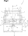
- Fig. 1 shows a front view of a bending press 1 in the form of a press brake, based on which the inventive principle is explained.
- the bending press 1 comprises a machine frame 2, with which a fixed table 3 is connected.
- the machine frame 2 is further supported by means of guide assemblies 4 a vertically adjustable pressing bar 5, wherein the adjustment is effected by drive means 6, for example in the form of hydraulic cylinders.
- the machine frame 2 comprises, in a common embodiment, two spaced-apart side cheeks 7, for example in the form of C-stands, which are connected by means of transverse connectors 8.
- At the table 3 and the pressing bar 5 are opposing or mutually facing support surfaces 9 and 10 are formed, on which cooperating bending tools 11 and 12 can be arranged.
- the bending tools can also be attached by means of their own tool receiving devices, the execution of the bending tools themselves or any adapter or tool holders is not relevant to the subject of the invention.
- a common form of the bending tools is an arrangement of a bending die on the support surface 9 of the table 3 and the attachment of a punch on the support surface 10 of the press beam 5.
- Bending tools 11 and 12 When approaching the press bar 5 to the table 3 can by cooperating Bending tools 11 and 12 forming forces are exerted on an inserted therebetween workpiece 13, whereby this is subjected to a bending deformation.
- the support surface 9 on the table 3 is thereby formed by a beam element 14 on the table 3 and the upper support surface 10 by a beam element 15 on the pressing beam 5.
- the beam elements 14 and 15 extend over the total length 16 of the table 3 and the press beam 5, whereby the bending tools 11, 12 can be selected and positioned according to the requirement of the workpieces 13 to be bent.
- the bending press 1 In order to prevent or reduce this disadvantageous effect, it is provided in the bending press 1 according to the invention, on the opposite support surface 9 on the table 3 to create a corresponding bow 17 corresponding to the curve 18. This results in a uniform degree of deformation of a workpiece to be bent 3 along the bending edge and a uniform, constant bending angle is achieved in a press brake.
- the lower beam element 14 on the table 3 is supported by a support structure 19 of the table 3 and an adjusting device 20 is arranged in the table 3, with which this cambered course 18 of the beam element 14 can be effected.
- the lower beam member 14 and the upper beam member 15 extend by this measure under the influence of forming forces at a constant distance, with the maximum deflection of the press beam at a total length 16 of the table 3, for example, 2500 mm in the range of a few millimeters, for example a maximum of 3 mm moves ,
- the deflection of the press beam 5 with the upper beam element 15 results essentially in the adjustment direction 21 of the press beam 5 and in the adjustment plane, which in Fig. 1 corresponds to the drawing plane.
- the lower beam element 14 In order to produce such a cambered course 18, the lower beam element 14 must be raised slightly upwards in the middle region upwards against the pressing direction, that is, in the illustrated embodiment, at least at the conclusion of the pressing process or forming process.
- the amount by which the lower beam element 14 must be raised can be calculated in advance by a controller in a good approximation, based on the known deflection behavior of the press beam 5, or the corresponding values for the required crowning of the lower beam element 14 can be known on the basis of series of tests on specific load situations be.
- the support structure 19 has an elongate support element 22, which has a helix angle 23 with respect to the adjustment direction 21 of the press beam.
- the adjusting device 20 comprises an actuator 24, for example in the form of a hydraulic cylinder, with which the helix angle 23 of the support element 22 within the table 3 can be changed. As in Fig. 1 is easy to see causes a reduction of the helix angle 23, a lifting of the beam member 14, whereby the cambered profile 18 is effected.
- a plurality of oblique support members 22 may be provided, the helix angle 23 by means of at least one actuator 24 can be changed.
- the support element 22 is at least slightly displaceable by its elongated design within the support structure 19 and the elongated embodiment is to be understood such that a longitudinal dimension of the support member 22 is greater than its dimension transverse to its longitudinal axis and in the direction of its slight displacement.
- the longitudinal dimension of the support element 22 is more than three times its cross-sectional dimension in the longitudinal direction of the beam element 14.
- the actuator 24 acts in the illustrated embodiment directly on the support member 22 and in turn is supported on the rest of the support structure 19, which are considered in the illustrated embodiment in comparison to the support member 22 as rigid and immovable can. That part of the supporting structure 19, on the table 3 or on the pressing beam 5, which can essentially be regarded as rigid, may also be referred to as the base section.
- the beam elements 14 and 15 are executed in the illustrated embodiment as separate components, but may also be an integral with the table 3 or pressing beam 5 related element.
- the longitudinal axis 25 of the support member 22 has with respect to the adjustment direction 21 a helix angle of preferably between 10 ° and 45 °, depending on the actual helix angle 23 different effects come to bear more.
- a relatively large helix angle 23 results in a good power transmission, that is, with relatively little force of the actuator 24, a high biasing force can be achieved on the beam member 14. If a relatively large helix angle 23 is selected, a better movement ratio is achieved, that is to say a small adjustment path on the actuator 24 causes a relatively large, vertical adjustment path for the prestressing of the beam element 14.
- the deflection 17 of the beam element 15 during a forming process will in many cases be substantially symmetrical with respect to a longitudinal plane of the beam element 14 perpendicular extending center plane 26 of the bending press 1 and it is therefore advantageous if the adjusting device 20 with the inclined support elements 22 so executed is that the cambered profile 18 of the lower beam member 14 is also effected symmetrically to the center plane 26.
- a very simplified embodiment of a support structure 19 is shown with a sloping support member 22, and are shown in sequence various embodiments of support structures 19, with which using a transverse to the adjustment 21 of the press beam acting on the support structure 19 actuator 24 a cambered course 18 of a Beam element 14 can be achieved.
- a support structure 19 with actively adjustable, inclined support member 22 is not limited to a table 3, but can of course also be used on a press bar 5 to a caused by the forming forces bending of the press bar 5 dddischen an opposite, active deformation of the beam element 15 balance. Accordingly, the above and following embodiments are also to be interpreted for embodiments of bending presses 1 in which such oblique support elements 22 are provided only on the table 3 or only on the pressing bars 5 or both on the table 3 and on the pressing bar 5.
- the support structure 19 includes in certain embodiments as a fixed part next to the adjustable support members 22 lein plate-like base member 27, such as those are also used in known from the prior art bending presses 1 both for the press table and for the pressing beam.
- columnar embodiments of support structures 19 are also conceivable, which likewise include oblique support elements 22 and actuators 24 acting thereon.
- An important effect of an oblique support element 22 is the comparatively great mobility in the adjustment direction 21, which is greater than in the case of support elements which are arranged parallel to the adjustment direction 21. This mobility is used in conjunction with the actuator 24 to bias a beam member 14 accordingly.
- support structures with oblique support members 22 may, as already described, by active reduction of the helix angle 23 a cambered profile 18 of the respective beam element 14 and 15 cause, but it is also possible by actively increasing the helix angle 23, a beam element 14 locally lower or to produce a concave profile 19. This could be applicable, for example, if the upper press beam 5 only comprises a drive means 6 in its central region.
- the lower end of the support element 22 is integrally formed on the base member 27 of the table 3, that is, the support member 22 is elastically deformed upon activation of the actuator 24 relative to the rest of the table 3 and the base member 27 and thereby the beam member 14 in the cambered History 18 brought.
- This deformation of the oblique support member 22 is made possible or substantially facilitated by its elongated embodiment.
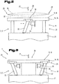
- Fig. 2 is a simplified view of a similar embodiment of a support structure 19 on a table 3 and a press bar 5 in a partial view of a bending press 1 shown.
- a sloping support member 22 is arranged, which can be changed by means of an actuator 24 in its helix angle 23.
- the end sections 29 of the beam element 14 or 15 are supported by a part of the support structure 19, which have a higher rigidity in the adjustment direction 21 at the end sections 29 than the inclined support element 22.
- the inclined support element 22 arranged in the middle region 28 can, as already described above, be replaced by a plurality of such inclined support members 22, 22 ', ....
- the support element 22 is moved to a steeper position, thereby slightly raising the beam element 14 in its middle region 28. Since this adjustment of the support member 22 shifts its upper end not only in the vertical direction but also in the horizontal direction, it is in such an arrangement of the support member 22 is advantageous if, as in Fig. 2 illustrated, between the upper end of the support member 22 and the beam member 14 is a movable in the longitudinal direction of the beam member 14 sliding bearing 30 is formed.
- Fig. 3 is a partial view of another embodiment of a support structure 19 for a beam element 14 of a bending press 1 is shown.
- the two end portions 29 of the beam member 14 are supported by obliquely extending support members 22, while the central portion 28 is supported by the rest of the support structure 19 and in the central portion 28 has a higher rigidity in the adjustment direction 21, as the inclined support members 22.
- the two support members 22 can be adjusted by actuators 24 in their position relative to the base portion 27 and with respect to the rest of the support structure 19 in its helix angle 23, whereby the end portions 29 of the beam member 14 can be actively adjusted. Again, it is possible depending on the operation of the actuators 24 and their arrangement, as already based on Fig.
- the support elements 22 can also have a helix angle of 0 ° with respect to the adjustment direction 21, which can be increased by the actuators 24 and thereby the beam element 14, 15 is adjusted.
- Fig. 3 illustrated variant could also be modified to the effect that the support elements 22 are slidably mounted at its lower end relative to the base member 27 by means of sliding bearings 30 and the actuators for lowering the lateral ends of the beam member 14, 15 at the lower end of the support elements 22 attack and in the direction of vertical mid-plane pressure forces can exercise.
- Fig. 3 is further indicated by dashed lines on the right support member 22 that it can also assume a helix angle of 0 ° in the normal position, which can be increased by the actuator 24, whereby also the course of the support surface 9, 10 can be actively changed.
- a detail of a further embodiment of a support structure 19 is shown, with which a beam element 14 can be adjusted under the action of an actuator 24 between a flat and a convex or concave curved course by a support member 22, which the beam member 14 relative to the rest of the support structure 19 that is, the base member 27, the rest of the table 3 or the press bar 5, supported and can be adjusted in its helix angle 23 by the actuator 24.
- the support element 22 has according to Fig. 4 two oblique sections 31 and 32, which extend obliquely with respect to the adjustment direction 21, wherein the helix angle 23 of the two inclined sections 31 and 32 in opposite directions with respect to the adjustment direction 21.
- the support member 22 is thus V-shaped and the two free ends of the V-angle with the beam member 14 and the base member 27 are connected.
- the two inclined portions 31 and 32 of the support member 22 may be connected to each other by means of a hinge 33, as well as the other ends of the inclined portions 31 and 32 may be articulated by means of joints 33 on the base member 27 and the beam member 14.
- joints 33 on the base member 27 and the beam member 14.
- the connection of the support member 22 may be performed on the base member 27 and the beam member 14 without joint.
- the special shape of the support member 22 with two opposing, oblique inclined portions 31 and 32, in which the actuator 24 engages transversely to the adjustment direction 21 in the middle of the support member 22 offers special advantages, since this embodiment of a support member 22 no horizontal relative displacement between the beam element 14 and the base member 27 causes, but only in the upper pivot point a lowering or lifting. In the area of small helix angles, for example below 30 °, this embodiment of a support element 22 also brings about a certain toggle effect, as a result of which large actuating forces can be exerted on the beam element 14 with relatively small actuating forces of the actuator 24. This effect can also be achieved if no separate joints 33 are provided or these are arranged only at certain points of the support element 22.
- the two inclined sections 31 and 32 have identical but opposing helix angles 23 and the two inclined sections 31 and 32 have identical lengths, that are substantially symmetrical with respect to a plane perpendicular to the adjustment direction 21 symmetry plane 34 are executed.
- the actuator 24 is in Fig. 4 simplified represented by an arrow, which also represents the optimal direction of force introduction, which is also substantially in the plane of symmetry 34 of the support element.
- Fig. 4 For the sake of simplicity, only a single support element 22 of a support structure 19 is shown, however, an arrangement of a plurality of support elements 22 is preferably provided in the various embodiments of a bending press, whereby the forces required or occurring during an adjustment process and a bending operation on several support elements 22nd to distribute. Furthermore, the trajectory 18 of the support surface 9 by the use of multiple support elements 22 is more uniform.
- Fig. 5 shows a partial view of another embodiment of a support structure 19 for a beam member 14 which includes a plurality of support members 22 which can be changed by means of an actuator 24 in its helix angle 23, and thereby the beam member 14 in the area above the support members 9 are actively raised or lowered can.
- the individual support elements 22 are arranged side by side in the longitudinal direction 35 of the beam element 14 below the beam member 14 and have in this embodiment, similar to the embodiment according to Fig. 4 in each case two inclined sections 31 and 32, the with respect to the adjustment direction 21 opposing helix angle 23 and with respect to a plane parallel to the longitudinal direction 35 symmetry plane 34 are arranged and executed substantially symmetrically.
- Adjacent support elements 22 in this case have an orientation in the same direction, ie corresponding inclined sections 31 and 32 adjacent support members 22 have in the same direction oriented helix angle 23.
- These helix angle 23 adjacent support members 22 may be identical, but it is also possible that the helix angle 23 of a support element 22 and the support portions 31 and 32 to the adjacent support member and the adjacent support portions 31 and 32 increases and decreases. As previously described, causes a larger helix angle 23 at the same adjustment of the actuator 24, a greater height adjustment of the beam member 14, as a smaller helix angle 23, whereby different helix angle 23 allow for the same adjustment of the actuator 24 locally different adjustments of the beam element 14 to achieve.
- each support element 23 can be actuated or adjusted by its own actuator 24, such as Fig. 5
- actuator 24 it is also possible that by means of a single actuator 24 a plurality of juxtaposed support members 22 can be adjusted simultaneously, whereby a small number of actuators 24, a large number of support members 22 can be adjusted.
- Adjacent support elements 22 are based in this case in particular in the direction of the introduction of force of the actuator 24 from each other, whereby the adjusting force of the actuator can be introduced into several consecutive support elements 22 at the same time.
- the mutual support of the support elements 22 is realized by webs 36 which connect adjacent support members 22 integrally with each other. It is of course also possible that between the individual support elements 22 separate spacers 37 are arranged, as in Fig. 5 indicated by dashed lines.
- the individual support elements 22 can be similar as in Fig. 4 be designed as separate components that connect the beam member 14 with the base member 27, but is also advantageous in Fig. 5 illustrated embodiment in which the herringbone structure 38 is formed by integrally connected support members 22 which is used as a single contiguous component between the base member 27 and beam member 14 or as shown also integrally connected to the base member 27.
- the herringbone structure 38 can also be integrated into the beam element 14 'in one piece, whereby, for example, the entire table 3 can consist of only one component.
- the individual support elements 22 can, as in Fig. 5 represented, are prepared in such a way that in a plate-like base member 27, a sequence of inclined with respect to the adjustment direction 21 slots 39 is introduced, whereby between adjacent slots, the individual support members 22 and support portions 31, 32 are formed.
- These slots 39 can be made for example by laser cutting with relatively little effort. With the help of programmable laser cutting machines such herringbone structures 38 can also be made very flexible and adapted to the requirements of a bending press 1.
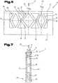
- FIG. 6 a further embodiment of a support structure 19 for a bending press 1 according to the invention is shown; and in Fig. 7 a cross section through a table 3 of a bending press 1 with a support structure 19 according to Fig. 6 ,
- the support structure 19 in Fig. 6 has a plurality of support members 22 formed with inclined portions 31 and 32 Stitzrauten 40 which support the beam member 14 either directly or, as in Fig. 6 shown, with the interposition of a cross connector 41 can act on the underside of the beam member 14.
- the support grooves 40 are mutually supported in the horizontal direction by means of actuators 24, with which also the respective helix angle 23 of the inclined sections 31, 32 can be adjusted and thus the curvature of the beam element 14 can be influenced.
- the two outer support rods 40 were supported by further actuators 24 relative to the base element 27 of the table 3.
- the upper and lower connection points of the support elements 22 are not displaced in the horizontal direction and therefore do not produce appreciable forces in the horizontal direction inter alia, the cross connector 41, as already described with reference to FIG Fig. 5 also form the beam element 14 '.
- this Stützrauten 40 in conjunction with the actuators 24 is similar to that of a scissors jack and can also be based on Fig. 4 described and also in Fig. 5 possible toggle effect can be achieved.
- actuators 24 preferably hydraulic cylinders are used which represent an optimal solution for the low adjustment path required and high adjustment forces.
- spindle drives In support structures in which larger adjustment of the support members 22 are required, the use of spindle drives is possible, in which case preferably a plurality of support members 22 are simultaneously adjusted by a spindle drive, since it would not be economical for each support member 22 to provide its own spindle drive.
- actuators 24 acting on the support elements 22 of a support structure 19 it is advantageous if these allow individually adjustable adjustment paths, as this also allows a curve 18 of the beam element 14 adapted to the respective application to be adjusted, which makes possible a deflection 17 of the press beam 5 in the best possible manner compensated.
- This individual control of the actuators 24 may be of an in Fig. 1
- the controller 42 which can also take into account, among other things, measured values of the deflection of the press beam 5 as well as measured values of the active deformation of the beam element 14, and a regulation of the course 18 of the support surface 9 based on measured values of the deflection of the beam Pressbar 5 can generate.
- the control can alternatively or additionally also be based on force measurements on the press beam 5 or on the beam element 4.
- Fig. 7 is a cross section through a table 3 of a bending press 1 according to the invention shown, wherein a support structure 19 according to Fig. 6 is used.
- the support structure 19 with the support elements 22 may, as Fig. 7 shows, be performed on both sides of the adjustment plane of the press bar 5 parallel guide plates 43 or aprons with little play, whereby a possible buckling of support members 22 can be avoided transversely to the adjustment of the press bar 5.
- the guide plates 43 can cause a substantial increase in the rigidity of the beam member 14 so that no local deformations of the beam element occur at punctual loads by bending operations with short bending edges.
- Fig. 7 shows in dashed lines nor the variant that the beam member 14 is connected to increase the rigidity with the guide plates 43.
- the guide plates 43 may further be connected to one another at their spaced from the beam member 14 end portions 44 by means of a lower chord 45 with each other, whereby the basic stiffness of the beam member can be further increased.
- the same effect as a separate lower flange 45 can also cause a fixation at the lower end of the base member 27.
- a further embodiment of a support structure 19 is shown, with which a support surface 9 of a beam member 14 can be adjusted starting from a flat initial state in a convex or concave curved course 18.
- the support structure in this case comprises a plurality of support elements 22, which are arranged symmetrically to a median plane 26 of the bending press and on both sides of the median plane 26 in the same direction oriented helix angle 23 have.
- the upper ends of the oblique support members 22 of a half are combined by means of a cross connector 41 and presses it on the underside of the beam member 14 when the actuators 24 which act in this embodiment on the cross connector 41 are activated.
- a displacement bearing. 30 provided, whereby no or no significant horizontal forces are transmitted between the cross connectors 41 and the beam member 14.
- the sliding support 30 is preferred formed by a sliding bearing, which is inexpensive to manufacture and has lower surface pressures than, for example, a rolling bearing.
- Fig. 9 shows a further embodiment of a support structure 19, which on both sides of the median plane 26 comprises a herringbone structure 38, which can be adjusted by means of lateral actuators 24 which are arranged in the region of the plane of symmetry 34 of the herringbone structures 38.
- lateral actuators 24 which are arranged in the region of the plane of symmetry 34 of the herringbone structures 38.
- the herringbone structures 38 according to Fig. 9 essentially correspond to those of the embodiments of Fig.
Landscapes
- Engineering & Computer Science (AREA)
- Mechanical Engineering (AREA)
- Bending Of Plates, Rods, And Pipes (AREA)
Claims (15)
- Presse à cintrer (1), comprenant une table fixe (3) reliée à un bâti de machine (2), une barre de pression (5) pouvant être déplacée le long d'agencements de guidage (4) sur le bâti de machine (2), à l'aide d'au moins un moyen d'entraînement (6) dans une direction vers et loin de la table (3), des surfaces d'appui (9, 10) opposées l'une par rapport à l'autre sur la table (3) et la barre de pression (5) pour des outils de cintrage (11, 12) et/ou des dispositifs porte-outils équitables, et un dispositif d'actionnement (20) sur la table (3) ou barre de pression (5) pour activer un déplacement d'une surface d'appui (9) entre un tracé essentiellement plat et un tracé bombé (19),dans lequel la surface d'appui (9) est formée d'un élément barre (14) de la table (3) ou de la barre de pression (5), s'étendant sur toute la longueur de la table (3) ou de la barre de pression (5), soutenu par une structure de support (19) de la table (3) ou de la barre de pression (5), caractérisée en ce que la structure de support (19) présente au moins un élément de support longitudinal (22) qui, par rapport à la direction de déplacement (21) de la barre de pression (5), peut occuper au moins partiellement un angle d'hélice (23), et le dispositif d'actionnement (20) comprend un actionneur (24) agissant transversalement par rapport à la direction de déplacement (21) sur la structure de support (19), en particulier l'élément de support (22), par l'intermédiaire duquel l'angle d'hélice (23) de l'élément de support (22) peut être modifié à l'intérieur de la table (3) et/ou de la barre de pression (5).
- Presse à cintrer (1) selon la revendication 1, caractérisée en ce que la structure de support (19) comprend une pluralité d'éléments de support (22) s'étendant en oblique.
- Presse à cintrer (1) selon la revendication 1 ou 2, caractérisée en ce que l'angle d'hélice (23) du au moins un élément de support en oblique (22) se trouve dans un plan parallèle au plan de déplacement de la barre de pression (5).
- Presse à cintrer (1) selon l'une quelconque des revendications précédentes, caractérisée en ce que le au moins un élément de support (22) est guidé entre deux plaques de guidage(43) parallèles au plan de déplacement de la barre de pression (5).
- Presse à cintrer (1) selon l'une quelconque des revendications précédentes, caractérisée en ce qu'une dimension longitudinale du au moins un élément de support (22), dans sa direction de support, correspond à au moins trois fois sa dimension en coupe transversale dans une direction parallèle à l'élément barre (14).
- Presse à cintrer (1) selon l'une quelconque des revendications précédentes, caractérisée en ce qu'entre l'élément de support (22) et l'élément barre (14) ou entre l'élément de support (22) et la partie fixe de la structure de support (19) est formé un support déplaçable (30) mobile dans la direction longitudinale de l'élément barre (14).
- Presse à cintrer (1) selon l'une quelconque des revendications précédentes, caractérisée en ce que les éléments de support (22) et les actionneurs (24) sont disposés symétriquement par rapport à un plan médian (26) s'étendant perpendiculairement à un axe longitudinal de l'élément barre (14) de la presse à cintrer (1).
- Presse à cintrer (1) selon l'une quelconque des revendications précédentes, caractérisée en ce qu'une pluralité d'éléments de support adjacents (22) sont formés à travers des fentes en oblique (39) dans un élément de base en forme de plaque (27) de la table (3) ou de la barre de pression (5), lesdites fentes (39) traversant complètement l'élément de base (27).
- Presse à cintrer (1) selon l'une quelconque des revendications précédentes, caractérisée en ce que l'angle d'hélice (23) des éléments de support (22) dans la section médiane (28) de l'élément barre (14) est plus grand que celui des éléments de support (22) agencés plus près des sections d'extrémité (29).
- Presse à cintrer (1) selon l'une quelconque des revendications précédentes, caractérisée en ce que l'angle d'hélice (23) de l'élément de support (22) ou des éléments de support (22), vis-à-vis de la direction de déplacement (21), est compris entre 0° et 45°.
- Presse à cintrer (1) selon l'une quelconque des revendications précédentes, caractérisée en ce que l'élément de support (22) ou les éléments de support (22) relatifs à un plan de symétrie (34) perpendiculaire par rapport à une direction de réglage (21) est ou sont conçus sous la forme d'une structure en arête de poisson (38) sensiblement symétrique à deux sections en oblique (31, 32) en sens inverse par rapport à la direction de déplacement (21) de la barre de pression (5), et la direction d'introduction de force de l'actionneur (24) s'étend sensiblement dans le plan de symétrie (34) de l'élément de support (22).
- Presse à cintrer (1) selon l'une quelconque des revendications précédentes, caractérisée en ce que la structure de support (19) comprend une pluralité d'éléments de support (22) ayant des losanges de support (40) formés par des sections de support (31, 32), et la direction d'introduction de force de l'actionneur (24) s'étend sensiblement dans le plan de symétrie (34) perpendiculaire à la direction de déplacement (21) des losanges de support (40).
- Presse à cintrer (1) selon l'une quelconque des revendications précédentes, caractérisée en ce que le au moins un élément de support (22), via au moins une extrémité, est monté sur l'élément barre (14), sur la structure de support (19), sur la table (3) ou sur la barre (5) au moyen d'une articulation (33).
- Presse à cintrer (1) selon l'une quelconque des revendications précédentes, caractérisée en ce que le au moins un élément de support (22), via au moins une extrémité, est formé d'un seul tenant avec l'élément barre (14), la structure de support (19), la table (3) ou la barre de pression (5).
- Presse à cintrer (1) selon l'une quelconque des revendications précédentes, caractérisée en ce que dans la structure de support (19) sont disposés plusieurs actionneurs (24) agissant sur les éléments de support (22) transversalement à la direction de déplacement (21), qui peuvent être commandés par une commande (42) de la presse à cintrer (1) et activés individuellement ou au moins par groupe dans différents trajets de déplacement.
Applications Claiming Priority (2)
| Application Number | Priority Date | Filing Date | Title |
|---|---|---|---|
| AT1822012A AT512174B1 (de) | 2012-02-13 | 2012-02-13 | Biegepresse mit verstellbarem balkenelement |
| PCT/AT2013/050036 WO2013120123A1 (fr) | 2012-02-13 | 2013-02-12 | Presse à cintrer doté d'élément barre réglable |
Publications (2)
| Publication Number | Publication Date |
|---|---|
| EP2814627A1 EP2814627A1 (fr) | 2014-12-24 |
| EP2814627B1 true EP2814627B1 (fr) | 2016-04-20 |
Family
ID=48039953
Family Applications (1)
| Application Number | Title | Priority Date | Filing Date |
|---|---|---|---|
| EP13713068.8A Not-in-force EP2814627B1 (fr) | 2012-02-13 | 2013-02-12 | Presse à cintrer doté d'élément barre réglable |
Country Status (3)
| Country | Link |
|---|---|
| EP (1) | EP2814627B1 (fr) |
| AT (1) | AT512174B1 (fr) |
| WO (1) | WO2013120123A1 (fr) |
Families Citing this family (7)
| Publication number | Priority date | Publication date | Assignee | Title |
|---|---|---|---|---|
| AT515130B1 (de) * | 2013-12-04 | 2015-08-15 | Trumpf Maschinen Austria Gmbh | Biegepresse |
| CN105234329A (zh) * | 2015-11-20 | 2016-01-13 | 合肥合锻机床股份有限公司 | 一种可调节上横梁结构 |
| CN112845704B (zh) * | 2021-01-06 | 2022-07-01 | 湖州学院 | 一种钣金件折弯成型设备 |
| EP4074432A1 (fr) * | 2021-04-15 | 2022-10-19 | Bystronic Laser AG | Machine à plier permettant de plier des pièces, en particulier presse plieuse |
| CN113426858B (zh) * | 2021-08-27 | 2021-11-05 | 佛山市阿玛达机械科技有限公司 | 一种防火门生产用门扇折弯成型装置及其使用方法 |
| CN114147104B (zh) * | 2021-11-30 | 2024-04-12 | 中芯晟捷(江苏)精密科技有限公司 | 一种铝合金锭加工成型用的折弯装置 |
| AT526736B1 (de) * | 2022-11-17 | 2025-08-15 | Trumpf Maschinen Austria Gmbh & Co Kg | Optimierter Tisch für Biegemaschine |
Family Cites Families (13)
| Publication number | Priority date | Publication date | Assignee | Title |
|---|---|---|---|---|
| US4426873A (en) | 1982-04-16 | 1984-01-24 | Canron Corporation | Deflection compensating means for press brakes and the like |
| JPH0688079B2 (ja) | 1986-03-25 | 1994-11-09 | 株式会社アマダ | プレスブレーキにおけるクラウニング装置 |
| FR2626802B1 (fr) * | 1988-02-05 | 1993-12-17 | Colly Ets A | Table a bombe reglable pour presse plieuse, marbre ou autre similaire |
| CH683162A5 (fr) * | 1990-04-25 | 1994-01-31 | Bobst Sa | Procédé d'asservissement du parallélisme des deux sommiers d'une presse à découper des éléments en forme de feuille ou bande en vue de la production d'emballages. |
| JPH0655219A (ja) * | 1992-08-07 | 1994-03-01 | Amada Co Ltd | ベンダーのクラウニング装置 |
| DE4235971C1 (de) | 1992-10-26 | 1994-04-07 | M & S Brugg Ag Brugg | Abkantpresse |
| JP2662858B2 (ja) * | 1995-05-24 | 1997-10-15 | 株式会社エナミ精機 | プレス加工機 |
| JP2001121214A (ja) * | 1999-10-27 | 2001-05-08 | Amada Co Ltd | プレスブレーキのクラウニング装置 |
| WO2001043896A1 (fr) | 1999-12-15 | 2001-06-21 | Trumpf Maschinen Austria Gmbh & Co. Kg. | Equipement de fabrication, en particulier presse plieuse |
| FR2942981B1 (fr) * | 2009-03-13 | 2011-04-08 | Amada Europe | Presse plieuse pour le pliage de feuilles |
| FR2942982B1 (fr) * | 2009-03-13 | 2014-12-05 | Amada Europ | Presse plieuse pour le pliage de feuilles |
| JP2011083800A (ja) * | 2009-10-16 | 2011-04-28 | Sumitomo Heavy Industries Techno-Fort Co Ltd | 曲げプレス |
| FI20105602A0 (fi) * | 2010-05-27 | 2010-05-27 | Aliko Automation Oy | Särmäyspuristin |
-
2012
- 2012-02-13 AT AT1822012A patent/AT512174B1/de not_active IP Right Cessation
-
2013
- 2013-02-12 EP EP13713068.8A patent/EP2814627B1/fr not_active Not-in-force
- 2013-02-12 WO PCT/AT2013/050036 patent/WO2013120123A1/fr not_active Ceased
Also Published As
| Publication number | Publication date |
|---|---|
| AT512174A4 (de) | 2013-06-15 |
| WO2013120123A1 (fr) | 2013-08-22 |
| EP2814627A1 (fr) | 2014-12-24 |
| AT512174B1 (de) | 2013-06-15 |
Similar Documents
| Publication | Publication Date | Title |
|---|---|---|
| EP2814627B1 (fr) | Presse à cintrer doté d'élément barre réglable | |
| AT504640B1 (de) | Biegemaschine | |
| DE3709555C2 (de) | Abkantpresse | |
| EP3077133B1 (fr) | Presse à cintrer | |
| DE102008035702A1 (de) | Walzvorrichtung | |
| EP3233321B1 (fr) | Pièce d'outil de moulage par compression et dispositif d'élimination des défauts de planéité sur des demi-produits plats | |
| EP3160726B1 (fr) | Presse à châssis en c, améliorée | |
| WO2001043896A1 (fr) | Equipement de fabrication, en particulier presse plieuse | |
| EP2362815B1 (fr) | Presse à cintrer dotée d'un dispositif support pour un moyen d'entraînement | |
| EP2691192B1 (fr) | Presse radiale | |
| DE102009023581A1 (de) | Presse, insbesondere kontinuierlich arbeitende Presse zur Herstellung von Werkstoffplatten | |
| AT507110B1 (de) | Presse zum umformen von material | |
| AT518538B1 (de) | Bearbeitungsmaschine zum Bearbeiten von Werkstücken | |
| EP2497580B1 (fr) | Outil de pliage et agencement d'outil de pliage | |
| DE1752346C3 (de) | Bombiervorrichtung für eine Abkantpresse | |
| EP2527116B1 (fr) | Presse continue et procédé utilisant une telle press | |
| EP2210680B1 (fr) | Presse plieuse dotée d'une poutre d'entraînement et d'une poutre plieuse couplée élastiquement | |
| DE102020133419B4 (de) | Anordnung, Verfahren und Richteinheit zum Rundbiegen des Endbereichs mit den beiden Enden spitzgebogener Rohre mit einer 3-Walzen-Biegemaschine | |
| DE60211080T2 (de) | Verstellbare Formmatrize, insbesondere für Abkantpressen | |
| DE2729938C3 (de) | Doppelbandpresse zum Herstellen von Preßplatten | |
| DE3400608C2 (de) | Walzgerüst mit einer zwischen Arbeitswalze und Stützwalze eingefügten versetzten Zwischenwalze | |
| EP2928680B1 (fr) | Presse plieuse | |
| AT526736B1 (de) | Optimierter Tisch für Biegemaschine | |
| EP0808668A2 (fr) | Dispositif d'application pour l'application directe ou indirecte d'un liquide ou d'une pâte sur une bande en défilement | |
| EP0879102B1 (fr) | Machine de cintrage circulaire des toles |
Legal Events
| Date | Code | Title | Description |
|---|---|---|---|
| PUAI | Public reference made under article 153(3) epc to a published international application that has entered the european phase |
Free format text: ORIGINAL CODE: 0009012 |
|
| 17P | Request for examination filed |
Effective date: 20140911 |
|
| AK | Designated contracting states |
Kind code of ref document: A1 Designated state(s): AL AT BE BG CH CY CZ DE DK EE ES FI FR GB GR HR HU IE IS IT LI LT LU LV MC MK MT NL NO PL PT RO RS SE SI SK SM TR |
|
| AX | Request for extension of the european patent |
Extension state: BA ME |
|
| DAX | Request for extension of the european patent (deleted) | ||
| GRAP | Despatch of communication of intention to grant a patent |
Free format text: ORIGINAL CODE: EPIDOSNIGR1 |
|
| INTG | Intention to grant announced |
Effective date: 20151102 |
|
| GRAS | Grant fee paid |
Free format text: ORIGINAL CODE: EPIDOSNIGR3 |
|
| GRAA | (expected) grant |
Free format text: ORIGINAL CODE: 0009210 |
|
| AK | Designated contracting states |
Kind code of ref document: B1 Designated state(s): AL AT BE BG CH CY CZ DE DK EE ES FI FR GB GR HR HU IE IS IT LI LT LU LV MC MK MT NL NO PL PT RO RS SE SI SK SM TR |
|
| REG | Reference to a national code |
Ref country code: GB Ref legal event code: FG4D Free format text: NOT ENGLISH |
|
| REG | Reference to a national code |
Ref country code: CH Ref legal event code: EP |
|
| REG | Reference to a national code |
Ref country code: AT Ref legal event code: REF Ref document number: 791829 Country of ref document: AT Kind code of ref document: T Effective date: 20160515 |
|
| REG | Reference to a national code |
Ref country code: IE Ref legal event code: FG4D Free format text: LANGUAGE OF EP DOCUMENT: GERMAN |
|
| REG | Reference to a national code |
Ref country code: DE Ref legal event code: R096 Ref document number: 502013002676 Country of ref document: DE |
|
| REG | Reference to a national code |
Ref country code: LT Ref legal event code: MG4D |
|
| REG | Reference to a national code |
Ref country code: NL Ref legal event code: MP Effective date: 20160420 |
|
| PG25 | Lapsed in a contracting state [announced via postgrant information from national office to epo] |
Ref country code: FI Free format text: LAPSE BECAUSE OF FAILURE TO SUBMIT A TRANSLATION OF THE DESCRIPTION OR TO PAY THE FEE WITHIN THE PRESCRIBED TIME-LIMIT Effective date: 20160420 Ref country code: NL Free format text: LAPSE BECAUSE OF FAILURE TO SUBMIT A TRANSLATION OF THE DESCRIPTION OR TO PAY THE FEE WITHIN THE PRESCRIBED TIME-LIMIT Effective date: 20160420 Ref country code: LT Free format text: LAPSE BECAUSE OF FAILURE TO SUBMIT A TRANSLATION OF THE DESCRIPTION OR TO PAY THE FEE WITHIN THE PRESCRIBED TIME-LIMIT Effective date: 20160420 Ref country code: PL Free format text: LAPSE BECAUSE OF FAILURE TO SUBMIT A TRANSLATION OF THE DESCRIPTION OR TO PAY THE FEE WITHIN THE PRESCRIBED TIME-LIMIT Effective date: 20160420 Ref country code: NO Free format text: LAPSE BECAUSE OF FAILURE TO SUBMIT A TRANSLATION OF THE DESCRIPTION OR TO PAY THE FEE WITHIN THE PRESCRIBED TIME-LIMIT Effective date: 20160720 |
|
| PG25 | Lapsed in a contracting state [announced via postgrant information from national office to epo] |
Ref country code: RS Free format text: LAPSE BECAUSE OF FAILURE TO SUBMIT A TRANSLATION OF THE DESCRIPTION OR TO PAY THE FEE WITHIN THE PRESCRIBED TIME-LIMIT Effective date: 20160420 Ref country code: LV Free format text: LAPSE BECAUSE OF FAILURE TO SUBMIT A TRANSLATION OF THE DESCRIPTION OR TO PAY THE FEE WITHIN THE PRESCRIBED TIME-LIMIT Effective date: 20160420 Ref country code: SE Free format text: LAPSE BECAUSE OF FAILURE TO SUBMIT A TRANSLATION OF THE DESCRIPTION OR TO PAY THE FEE WITHIN THE PRESCRIBED TIME-LIMIT Effective date: 20160420 Ref country code: HR Free format text: LAPSE BECAUSE OF FAILURE TO SUBMIT A TRANSLATION OF THE DESCRIPTION OR TO PAY THE FEE WITHIN THE PRESCRIBED TIME-LIMIT Effective date: 20160420 Ref country code: GR Free format text: LAPSE BECAUSE OF FAILURE TO SUBMIT A TRANSLATION OF THE DESCRIPTION OR TO PAY THE FEE WITHIN THE PRESCRIBED TIME-LIMIT Effective date: 20160721 Ref country code: PT Free format text: LAPSE BECAUSE OF FAILURE TO SUBMIT A TRANSLATION OF THE DESCRIPTION OR TO PAY THE FEE WITHIN THE PRESCRIBED TIME-LIMIT Effective date: 20160822 Ref country code: ES Free format text: LAPSE BECAUSE OF FAILURE TO SUBMIT A TRANSLATION OF THE DESCRIPTION OR TO PAY THE FEE WITHIN THE PRESCRIBED TIME-LIMIT Effective date: 20160420 |
|
| PG25 | Lapsed in a contracting state [announced via postgrant information from national office to epo] |
Ref country code: IT Free format text: LAPSE BECAUSE OF FAILURE TO SUBMIT A TRANSLATION OF THE DESCRIPTION OR TO PAY THE FEE WITHIN THE PRESCRIBED TIME-LIMIT Effective date: 20160420 |
|
| REG | Reference to a national code |
Ref country code: DE Ref legal event code: R097 Ref document number: 502013002676 Country of ref document: DE |
|
| PG25 | Lapsed in a contracting state [announced via postgrant information from national office to epo] |
Ref country code: SK Free format text: LAPSE BECAUSE OF FAILURE TO SUBMIT A TRANSLATION OF THE DESCRIPTION OR TO PAY THE FEE WITHIN THE PRESCRIBED TIME-LIMIT Effective date: 20160420 Ref country code: CZ Free format text: LAPSE BECAUSE OF FAILURE TO SUBMIT A TRANSLATION OF THE DESCRIPTION OR TO PAY THE FEE WITHIN THE PRESCRIBED TIME-LIMIT Effective date: 20160420 Ref country code: DK Free format text: LAPSE BECAUSE OF FAILURE TO SUBMIT A TRANSLATION OF THE DESCRIPTION OR TO PAY THE FEE WITHIN THE PRESCRIBED TIME-LIMIT Effective date: 20160420 Ref country code: EE Free format text: LAPSE BECAUSE OF FAILURE TO SUBMIT A TRANSLATION OF THE DESCRIPTION OR TO PAY THE FEE WITHIN THE PRESCRIBED TIME-LIMIT Effective date: 20160420 Ref country code: RO Free format text: LAPSE BECAUSE OF FAILURE TO SUBMIT A TRANSLATION OF THE DESCRIPTION OR TO PAY THE FEE WITHIN THE PRESCRIBED TIME-LIMIT Effective date: 20160420 |
|
| REG | Reference to a national code |
Ref country code: FR Ref legal event code: PLFP Year of fee payment: 5 |
|
| PLBE | No opposition filed within time limit |
Free format text: ORIGINAL CODE: 0009261 |
|
| STAA | Information on the status of an ep patent application or granted ep patent |
Free format text: STATUS: NO OPPOSITION FILED WITHIN TIME LIMIT |
|
| PG25 | Lapsed in a contracting state [announced via postgrant information from national office to epo] |
Ref country code: SM Free format text: LAPSE BECAUSE OF FAILURE TO SUBMIT A TRANSLATION OF THE DESCRIPTION OR TO PAY THE FEE WITHIN THE PRESCRIBED TIME-LIMIT Effective date: 20160420 |
|
| 26N | No opposition filed |
Effective date: 20170123 |
|
| PG25 | Lapsed in a contracting state [announced via postgrant information from national office to epo] |
Ref country code: BE Free format text: LAPSE BECAUSE OF NON-PAYMENT OF DUE FEES Effective date: 20170228 Ref country code: SI Free format text: LAPSE BECAUSE OF FAILURE TO SUBMIT A TRANSLATION OF THE DESCRIPTION OR TO PAY THE FEE WITHIN THE PRESCRIBED TIME-LIMIT Effective date: 20160420 |
|
| PG25 | Lapsed in a contracting state [announced via postgrant information from national office to epo] |
Ref country code: MC Free format text: LAPSE BECAUSE OF FAILURE TO SUBMIT A TRANSLATION OF THE DESCRIPTION OR TO PAY THE FEE WITHIN THE PRESCRIBED TIME-LIMIT Effective date: 20160420 |
|
| REG | Reference to a national code |
Ref country code: CH Ref legal event code: PL |
|
| GBPC | Gb: european patent ceased through non-payment of renewal fee |
Effective date: 20170212 |
|
| PG25 | Lapsed in a contracting state [announced via postgrant information from national office to epo] |
Ref country code: LI Free format text: LAPSE BECAUSE OF NON-PAYMENT OF DUE FEES Effective date: 20170228 Ref country code: CH Free format text: LAPSE BECAUSE OF NON-PAYMENT OF DUE FEES Effective date: 20170228 |
|
| REG | Reference to a national code |
Ref country code: IE Ref legal event code: MM4A |
|
| PG25 | Lapsed in a contracting state [announced via postgrant information from national office to epo] |
Ref country code: LU Free format text: LAPSE BECAUSE OF NON-PAYMENT OF DUE FEES Effective date: 20170212 |
|
| REG | Reference to a national code |
Ref country code: BE Ref legal event code: MM Effective date: 20170228 |
|
| REG | Reference to a national code |
Ref country code: FR Ref legal event code: PLFP Year of fee payment: 6 |
|
| PG25 | Lapsed in a contracting state [announced via postgrant information from national office to epo] |
Ref country code: GB Free format text: LAPSE BECAUSE OF NON-PAYMENT OF DUE FEES Effective date: 20170212 Ref country code: IE Free format text: LAPSE BECAUSE OF NON-PAYMENT OF DUE FEES Effective date: 20170212 |
|
| PG25 | Lapsed in a contracting state [announced via postgrant information from national office to epo] |
Ref country code: MT Free format text: LAPSE BECAUSE OF FAILURE TO SUBMIT A TRANSLATION OF THE DESCRIPTION OR TO PAY THE FEE WITHIN THE PRESCRIBED TIME-LIMIT Effective date: 20160420 |
|
| PG25 | Lapsed in a contracting state [announced via postgrant information from national office to epo] |
Ref country code: AL Free format text: LAPSE BECAUSE OF FAILURE TO SUBMIT A TRANSLATION OF THE DESCRIPTION OR TO PAY THE FEE WITHIN THE PRESCRIBED TIME-LIMIT Effective date: 20160420 |
|
| REG | Reference to a national code |
Ref country code: AT Ref legal event code: MM01 Ref document number: 791829 Country of ref document: AT Kind code of ref document: T Effective date: 20180212 |
|
| PG25 | Lapsed in a contracting state [announced via postgrant information from national office to epo] |
Ref country code: AT Free format text: LAPSE BECAUSE OF NON-PAYMENT OF DUE FEES Effective date: 20180212 |
|
| PGFP | Annual fee paid to national office [announced via postgrant information from national office to epo] |
Ref country code: PL Payment date: 20190313 Year of fee payment: 7 |
|
| PG25 | Lapsed in a contracting state [announced via postgrant information from national office to epo] |
Ref country code: HU Free format text: LAPSE BECAUSE OF FAILURE TO SUBMIT A TRANSLATION OF THE DESCRIPTION OR TO PAY THE FEE WITHIN THE PRESCRIBED TIME-LIMIT; INVALID AB INITIO Effective date: 20130212 |
|
| PG25 | Lapsed in a contracting state [announced via postgrant information from national office to epo] |
Ref country code: BG Free format text: LAPSE BECAUSE OF FAILURE TO SUBMIT A TRANSLATION OF THE DESCRIPTION OR TO PAY THE FEE WITHIN THE PRESCRIBED TIME-LIMIT Effective date: 20160420 |
|
| PG25 | Lapsed in a contracting state [announced via postgrant information from national office to epo] |
Ref country code: CY Free format text: LAPSE BECAUSE OF FAILURE TO SUBMIT A TRANSLATION OF THE DESCRIPTION OR TO PAY THE FEE WITHIN THE PRESCRIBED TIME-LIMIT Effective date: 20160420 |
|
| PG25 | Lapsed in a contracting state [announced via postgrant information from national office to epo] |
Ref country code: MK Free format text: LAPSE BECAUSE OF FAILURE TO SUBMIT A TRANSLATION OF THE DESCRIPTION OR TO PAY THE FEE WITHIN THE PRESCRIBED TIME-LIMIT Effective date: 20160420 |
|
| PG25 | Lapsed in a contracting state [announced via postgrant information from national office to epo] |
Ref country code: TR Free format text: LAPSE BECAUSE OF FAILURE TO SUBMIT A TRANSLATION OF THE DESCRIPTION OR TO PAY THE FEE WITHIN THE PRESCRIBED TIME-LIMIT Effective date: 20160420 |
|
| PG25 | Lapsed in a contracting state [announced via postgrant information from national office to epo] |
Ref country code: IS Free format text: LAPSE BECAUSE OF FAILURE TO SUBMIT A TRANSLATION OF THE DESCRIPTION OR TO PAY THE FEE WITHIN THE PRESCRIBED TIME-LIMIT Effective date: 20160820 |
|
| PG25 | Lapsed in a contracting state [announced via postgrant information from national office to epo] |
Ref country code: FR Free format text: LAPSE BECAUSE OF NON-PAYMENT OF DUE FEES Effective date: 20200229 |
|
| PGFP | Annual fee paid to national office [announced via postgrant information from national office to epo] |
Ref country code: DE Payment date: 20211213 Year of fee payment: 10 |
|
| REG | Reference to a national code |
Ref country code: DE Ref legal event code: R119 Ref document number: 502013002676 Country of ref document: DE |
|
| PG25 | Lapsed in a contracting state [announced via postgrant information from national office to epo] |
Ref country code: DE Free format text: LAPSE BECAUSE OF NON-PAYMENT OF DUE FEES Effective date: 20230901 |