EP2815212B1 - Sensor mit einem magneten und einer halleffektsonde - Google Patents
Sensor mit einem magneten und einer halleffektsonde Download PDFInfo
- Publication number
- EP2815212B1 EP2815212B1 EP13710454.3A EP13710454A EP2815212B1 EP 2815212 B1 EP2815212 B1 EP 2815212B1 EP 13710454 A EP13710454 A EP 13710454A EP 2815212 B1 EP2815212 B1 EP 2815212B1
- Authority
- EP
- European Patent Office
- Prior art keywords
- sensor
- magnet
- effect probe
- axis
- hall effect
- Prior art date
- Legal status (The legal status is an assumption and is not a legal conclusion. Google has not performed a legal analysis and makes no representation as to the accuracy of the status listed.)
- Not-in-force
Links
- 239000000523 sample Substances 0.000 title claims description 76
- 230000005355 Hall effect Effects 0.000 title claims description 70
- 230000006698 induction Effects 0.000 claims description 19
- 238000006073 displacement reaction Methods 0.000 description 13
- 239000011347 resin Substances 0.000 description 6
- 229920005989 resin Polymers 0.000 description 6
- 239000002184 metal Substances 0.000 description 2
- 238000005266 casting Methods 0.000 description 1
- 230000007423 decrease Effects 0.000 description 1
- 238000004519 manufacturing process Methods 0.000 description 1
- 238000000034 method Methods 0.000 description 1
- 238000000465 moulding Methods 0.000 description 1
- 230000001681 protective effect Effects 0.000 description 1
Images

Classifications
-
- G—PHYSICS
- G01—MEASURING; TESTING
- G01D—MEASURING NOT SPECIALLY ADAPTED FOR A SPECIFIC VARIABLE; ARRANGEMENTS FOR MEASURING TWO OR MORE VARIABLES NOT COVERED IN A SINGLE OTHER SUBCLASS; TARIFF METERING APPARATUS; MEASURING OR TESTING NOT OTHERWISE PROVIDED FOR
- G01D5/00—Mechanical means for transferring the output of a sensing member; Means for converting the output of a sensing member to another variable where the form or nature of the sensing member does not constrain the means for converting; Transducers not specially adapted for a specific variable
- G01D5/12—Mechanical means for transferring the output of a sensing member; Means for converting the output of a sensing member to another variable where the form or nature of the sensing member does not constrain the means for converting; Transducers not specially adapted for a specific variable using electric or magnetic means
- G01D5/14—Mechanical means for transferring the output of a sensing member; Means for converting the output of a sensing member to another variable where the form or nature of the sensing member does not constrain the means for converting; Transducers not specially adapted for a specific variable using electric or magnetic means influencing the magnitude of a current or voltage
- G01D5/142—Mechanical means for transferring the output of a sensing member; Means for converting the output of a sensing member to another variable where the form or nature of the sensing member does not constrain the means for converting; Transducers not specially adapted for a specific variable using electric or magnetic means influencing the magnitude of a current or voltage using Hall-effect devices
- G01D5/147—Mechanical means for transferring the output of a sensing member; Means for converting the output of a sensing member to another variable where the form or nature of the sensing member does not constrain the means for converting; Transducers not specially adapted for a specific variable using electric or magnetic means influencing the magnitude of a current or voltage using Hall-effect devices influenced by the movement of a third element, the position of Hall device and the source of magnetic field being fixed in respect to each other
-
- G—PHYSICS
- G01—MEASURING; TESTING
- G01V—GEOPHYSICS; GRAVITATIONAL MEASUREMENTS; DETECTING MASSES OR OBJECTS; TAGS
- G01V3/00—Electric or magnetic prospecting or detecting; Measuring magnetic field characteristics of the earth, e.g. declination, deviation
- G01V3/08—Electric or magnetic prospecting or detecting; Measuring magnetic field characteristics of the earth, e.g. declination, deviation operating with magnetic or electric fields produced or modified by objects or geological structures or by detecting devices
Definitions
- the present invention relates to a sensor comprising a magnet and a Hall effect probe for detecting whether a metal moving object is in front of the Hall effect probe, and a magnet for such a sensor.
- Such a sensor is used for example to detect the position of the axis of the clutch of a gearbox, or the position of the camshaft (s).
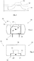
- the Fig. 1 shows a curve which represents the variations of the magnetic induction as a function of the position of the moving object with respect to the Hall effect probe. The value of the magnetic induction decreases as the moving object moves away from the Hall effect probe.
- TPO Truste Power ON
- This function thus makes it possible to determine at startup if the moving object is vis-à-vis the Hall effect probe or not.
- a threshold value 12 of the magnetic induction is set at the factory.
- the value of the magnetic induction seen by the Hall effect probe is greater than the threshold value 12, this is interpreted as the fact that the moving object is opposite the the Hall effect probe.
- the value of the magnetic induction seen by the Hall effect probe is lower than the threshold value 12, this is interpreted as the fact that the moving object is not visible. to the Hall effect probe.
- Curve 14 is the curve representative of the variations in magnetic induction after displacement of the Hall effect probe.
- the threshold value 12 is no longer reached after the movement of the Hall effect probe and the TPO function is no longer fulfilled.
- Fixing is carried out for example by casting a resin in the sensor including the Hall effect probe.
- Document is known US 5,637,995 , a sensor consisting of a probe comprising a sensitive element, a permanent magnet, a housing and a cap.
- the permanent magnet has a cavity and a through hole extending along the central axis of the permanent magnet. The through hole communicates with the cavity.
- the probe extends along the through hole and into the cavity, the sensing element being housed at the cavity.
- the permanent magnet and the probe are held in place by the housing and the cap.
- the probe is held in place in the magnet so as to come into permanent contact with the cap.
- An object of the present invention is to provide a sensor comprising a magnet and a Hall effect probe which do not have the drawbacks of the prior art.
- the cylindrical hole makes it possible to lower the magnetic induction, in particular so that the latter reaches a value of about zero Gauss at the sensitive element of the Hall effect probe.
- the cylindrical hole may have a circular cross section.
- the bottom of the cavity may define a transverse plane, in particular perpendicular to the axis of the cylindrical hole.
- the Hall effect probe can be housed in the cavity.
- This plane can form a stop for the displacement along the axis of the cylindrical hole of the Hall effect probe.
- the movement of the Hall effect probe inside the cavity may involve no displacement thereof within the cylindrical hole.
- the probe can remain out of the hole.
- the dimension, measured perpendicular to the axis of the cylindrical hole of the probe is in particular greater than the dimension of the cylindrical hole, perpendicular to the axis of the cylindrical hole.
- the displacement of the probe can be done exclusively outside the hole.
- the Hall effect probe does not lodge, even partially, in the cylindrical hole.
- the cylindrical hole is blind, that is to say that only one end of the hole along its axis is open, the other being closed.
- the cavity can open out of the magnet by two openings arranged parallel to the axis of the hole. These openings may or may not also be formed in the hole.
- the cylindrical hole can open out of the magnet by two openings disposed parallel to the axis of said hole.
- the openings may be diametrically opposed along the axis of the hole.
- the hole is blind and opens out of the magnet by two openings disposed parallel to the axis of said hole.
- one of the ends of the hole along its axis is closed and two openings are formed on either side of said axis, the openings being in particular diametrically opposite.
- the dimensions of the magnet are such that during displacements of the Hall effect probe, the value of the magnetic induction perceived by the sensitive element remains substantially constant.
- the dimensions of the magnet are such that the variations of the magnetic induction perceived by the sensitive element during displacements of the Hall effect probe are not likely to displace the curve representative of the magnetic field with respect to the threshold value. corresponding to the TPO.
- the TPO function therefore remains operational.
- the dimensions of the magnet may be such that, in the tolerance range of the displacements of the Hall effect probe, the value of the magnetic induction perceived by the sensitive element remains substantially constant.
- the cavity may have a parallelepipedal shape.
- the probe can then have a shape allowing it to be received in the cavity.
- the sensor may comprise a support and the Hall effect probe may be fixed to this support, for example only via connection tabs.
- These tabs may be flexible and this flexibility of the probe lead tabs may allow the probe to move into the cavity.
- the magnet and the Hall effect probe can each be connected, directly or indirectly, to the same support.
- the magnet and the Hall effect probe may each be integral with this same support.
- the support may be a sensor housing.
- the magnet and the Hall effect probe may not be rigidly coupled together unlike what would be the case if a resin were used to immobilize the magnet with respect to the Hall effect probe.
- the magnet and the Hall effect probe can thus both be connected to the same support without the magnet and the Hall effect probe being rigidly coupled to each other.
- the Hall effect probe may move in the cavity in a direction parallel to the axis of the hole and / or in a plane perpendicular to said axis.
- the invention also proposes a magnet for a sensor according to one of the preceding embodiments, said magnet having a cavity having a bottom and intended to house a sensitive element of a Hall effect probe, and a cylindrical hole having an axis. and extending from said bottom to the inside of the magnet.
- the cylindrical hole is blind.
- the Fig. 2 shows a sensor 20 according to the invention in front view and the Fig. 3 shows the sensor 20 in top view.
- the sensor 20 comprises a magnet 30 and a hall effect probe 21.
- the sensor 20 also comprises a not shown base on which the magnet 30 is fixed.
- the Hall effect sensor 21 comprises a sensitive element 23 and is fixed on a printed circuit (not shown) or on tabs via its connecting tabs 22.
- the printed circuit is itself fixed on the base which can form a protective housing in which are housed the magnet 30, the Hall effect sensor 21 and the printed circuit.
- the magnet 30 has an open cavity 32 having a bottom 31 and in which is housed the Hall effect probe 21 and more particularly the sensitive element 23.
- the cavity 32 takes in the example described the shape of a parallelepiped which is limited by the bottom 31 and which is open on the face opposite to the bottom 31.
- the parallelepiped is limited by the magnet 30, along two of its other parallel faces, and it is open along the last two parallel faces.
- the Hall effect probe 21 is driven into the cavity 32. A portion of the magnet 30 is opposite two of the parallel edges of the Hall effect probe 21.
- the magnet 30 also has a cylindrical hole 33 having an axis 34 and which extends from the bottom 31 towards the inside of the magnet 30.
- the axis 34 is perpendicular to the bottom 31, that is to say in the plane in which the Hall effect probe 21 extends.
- the cylindrical hole 33 is blind.
- the dimensions of the hole 33 may depend on the dimensions of the magnet 30, in particular its dimension along the axis 34 and those in a plane perpendicular to this axis 34, and / or the dimensions of the cavity 32.
- the magnet 30 is generally symmetrical with respect to one of the planes passing through the axis 34.
- the preferred position of the sensitive element 23, when the sensor 20 is assembled, is such that the sensitive element 23 is housed in the cavity 32 and is positioned on the axis 34.
- the Hall effect probe 21 is not fixed by means of a resin. In the example described, it is only fixed by means of its connecting lugs 22 which leave the cavity 32 by one of the last two open faces of the parallelepiped. The Hall effect probe 21 is thus able to move relative to the magnet 30 in a tolerance range around the preferred position.
- the tolerance range is defined by the manufacturing tolerances of the components, the component mounting tolerances between them and the shifts that occur during the life of the sensor 20.
- the sensitive element 23 is thus able to move in the cavity 32 in a first direction parallel to the axis 34 and in a plane parallel to the bottom 31 about the axis 34.
- the length of the bottom 31 is in particular determined to allow the introduction of the Hall effect probe 21 and limit the displacements of the Hall effect probe 21 in the cavity 32.
- the dimensions of the magnet 30 are such that the variations of the magnetic induction perceived by the sensitive element 23 during displacements of the Hall effect probe 21 are not likely to displace the curve representative of the magnetic field with respect to the threshold value corresponding to the TPO.
- the TPO function therefore remains operational.
- the dimensions of the magnet 30 are such that, in the displacement tolerance range of the Hall effect probe 21, the value of the magnetic induction perceived by the sensitive element 23 remains substantially constant. .
- the Fig. 6 is a graph showing the magnetic induction perceived by the sensing element 23 as a function of the position of the sensing element 23 along the axis 34.
- the zero of the abscissa axis corresponds to the theoretical position of the sensitive element 23 as defined during the design of the sensor 20, that is to say when the sensitive element 23 is on the 34 axis and when the Hall effect probe 21 is in the bottom of the cavity 32.
- Each division of the abscissa axis corresponds to 0.5 mm. Due to its possible displacement while remaining within the tolerance range, the actual position of the Hall effect probe 21 varies from 0 mm (position at the bottom of the cavity 32) to -0.5 mm (position removed from the bottom of the cavity 32).
- the zero of the y-axis corresponds to 0 G.
- Each division of the y-axis corresponds to 500 G.
- Curve 61 corresponds to the magnetic induction perceived by the sensitive element of a Hall effect probe of a sensor of the state of the art.
- the curve 62 corresponds to the magnetic induction perceived by the sensitive element 23 of the Hall effect probe 21 of the sensor 20 according to the invention.
- the variation of the magnetic induction in the displacement range of the sensitive element is about 300 G.
- the variation of the magnetic induction in the displacement range of the sensitive element 23 is of the order of 10 G.
- the magnet 30 is for example obtained by molding. Alternatively, the magnet is a compressed, sintered or machined magnet.
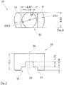
- the Fig. 4 and the Fig. 5 show a particular embodiment of the magnet 30 in front view and in top view in the case where the Hall effect sensor 21 is a probe INFINEON and referenced TLE 498x.
- the magnet 30 consists of a height block (measured along the axis 34) of 5.5 mm.
- the block is a portion of a cylinder of diameter 10 mm centered on the axis 34.
- the cylinder is bounded by two parallel planes and symmetrical with respect to the axis 34. The distance between the two planes is 4.92 mm .
- the cavity 32 has a rectangular shape centered on the axis 34 and perpendicular to the planes limiting the cylinder.
- the length of the bottom 31 parallel to the planes is 5.47 mm and the width of the bottom 31 perpendicular to the planes is 4.92 mm.
- the height of the cavity 32 parallel to the axis 34 is 1.08 mm.
- the cylindrical hole 33 has a diameter of 4.9 mm and a height (measured along the axis 34) relative to the bottom 31 of 1.75 mm.
- the wall limiting the cylindrical hole 33 opens in the example considered on each of the planes limiting the cylinder by a slot perpendicular to said plane and having a width of 2.6 mm distributed symmetrically on either side of the axis 34.
Landscapes
- Physics & Mathematics (AREA)
- General Physics & Mathematics (AREA)
- Life Sciences & Earth Sciences (AREA)
- Engineering & Computer Science (AREA)
- Remote Sensing (AREA)
- Environmental & Geological Engineering (AREA)
- Electromagnetism (AREA)
- Geology (AREA)
- General Life Sciences & Earth Sciences (AREA)
- Geophysics (AREA)
- Transmission And Conversion Of Sensor Element Output (AREA)
- Measuring Magnetic Variables (AREA)
- Measurement Of Length, Angles, Or The Like Using Electric Or Magnetic Means (AREA)
- Hall/Mr Elements (AREA)
Claims (10)
- Sensor (20), umfassend:- eine Hall-Effekt-Sonde (21), umfassend ein empfindliches Element (23),- einen Magneten (30), der eine Kavität (32) aufweist, die einen Boden (31) aufweist und in der das sensible Element (23) aufgenommen ist, und ein zylindrisches Loch (33), das eine Achse (34) hat und das sich ausgehend von dem Boden (31) zum Inneren des Magneten (30) hin erstreckt, wobei die Hall-Effekt-Sonde innerhalb der Kavität (32) und außerhalb des Lochs (33) bewegbar ist, dadurch gekennzeichnet, dass die Abmessungen des Magneten (30) derart sind, dass bei Bewegungen der Hall-Effekt-Sonde (21) der Wert der magnetischen Induktivität, der vom sensiblen Element (23) wahrgenommen wird, im Wesentlichen konstant bleibt.
- Sensor (20) nach Anspruch 1, wobei das zylindrische Loch (33) einen kreisförmigen Querschnitt aufweist.
- Sensor (20) nach Anspruch 1 oder 2, wobei der Boden der Kavität (32) eine Querebene definiert, insbesondere senkrecht zur Achse des zylindrischen Lochs (33).
- Sensor (20) nach Anspruch 3, wobei die Querebene einen Anschlag für die Bewegung der Hall-Effekt-Sonde (21) entlang der Achse des zylindrischen Lochs (33) bildet.
- Sensor (20) nach einem der vorhergehenden Ansprüche, wobei das zylindrische Loch (33) ein Sackloch ist.
- Sensor (20) nach einem der vorhergehenden Ansprüche, wobei die Kavität (32) eine parallelepipedische Form hat.
- Sensor (20) nach einem der vorhergehenden Ansprüche, wobei der Magnet (30) und die Hall-Effekt-Sonde (21) nicht starr gekoppelt sind.
- Sensor (20) nach einem der vorhergehenden Ansprüche, wobei sich die Hall-Effekt-Sonde (21) entlang einer Richtung parallel zur Achse (34) des Lochs (33) und/oder in einer Ebene senkrecht zu der Achse (34) bewegen kann.
- Sensor (20) nach Anspruch 8, wobei sich die Hall-Effekt-Sonde (21) ausschließlich in Ebenen senkrecht zu der Achse (34) bewegt.
- Sensor nach einem der vorhergehenden Ansprüche, umfassend einen Träger, wobei der Magnet (30) und die Hall-Effekt-Sonde (21) jeweils mit diesem Träger verbunden sind.
Applications Claiming Priority (2)
| Application Number | Priority Date | Filing Date | Title |
|---|---|---|---|
| FR1251433A FR2987115B1 (fr) | 2012-02-16 | 2012-02-16 | Capteur comprenant un aimant et une sonde a effet hall |
| PCT/FR2013/050303 WO2013121153A1 (fr) | 2012-02-16 | 2013-02-14 | Capteur comprenant un aimant et une sonde a effet hall |
Publications (2)
| Publication Number | Publication Date |
|---|---|
| EP2815212A1 EP2815212A1 (de) | 2014-12-24 |
| EP2815212B1 true EP2815212B1 (de) | 2019-01-02 |
Family
ID=47901168
Family Applications (1)
| Application Number | Title | Priority Date | Filing Date |
|---|---|---|---|
| EP13710454.3A Not-in-force EP2815212B1 (de) | 2012-02-16 | 2013-02-14 | Sensor mit einem magneten und einer halleffektsonde |
Country Status (8)
| Country | Link |
|---|---|
| US (1) | US9683868B2 (de) |
| EP (1) | EP2815212B1 (de) |
| JP (1) | JP2015515603A (de) |
| KR (1) | KR20140132735A (de) |
| CN (1) | CN104169686B (de) |
| BR (1) | BR112014020017A8 (de) |
| FR (1) | FR2987115B1 (de) |
| WO (1) | WO2013121153A1 (de) |
Citations (1)
| Publication number | Priority date | Publication date | Assignee | Title |
|---|---|---|---|---|
| US20020011837A1 (en) * | 2000-07-11 | 2002-01-31 | Yazaki Corporation | Rotation angle sensor |
Family Cites Families (13)
| Publication number | Priority date | Publication date | Assignee | Title |
|---|---|---|---|---|
| US3663843A (en) * | 1971-03-19 | 1972-05-16 | Nasa | Hall effect transducer |
| JPS5845501A (ja) * | 1981-09-11 | 1983-03-16 | Nippon Soken Inc | 運動する被検出体の運動位置検出装置 |
| US5115194A (en) * | 1990-09-27 | 1992-05-19 | Kearney-National Inc. | Hall effect position sensor with flux limiter and magnetic dispersion means |
| US5637995A (en) * | 1992-12-09 | 1997-06-10 | Nippondenso Co., Ltd. | Magnetic detection device having a magnet including a stepped portion for eliminating turbulence at the MR sensor |
| DE9414104U1 (de) * | 1994-08-31 | 1994-11-03 | Siemens AG, 80333 München | Näherungsschalter mit magnetempfindlichem Sensor |
| FR2724723B1 (fr) * | 1994-09-16 | 1998-09-11 | Moving Magnet Tech | Capteur incremental de vitesse et/ou de position. |
| DE10141371A1 (de) * | 2001-08-23 | 2003-03-13 | Philips Corp Intellectual Pty | Magnetoresistive Sensoreinrichtung |
| CN101124465A (zh) * | 2005-02-01 | 2008-02-13 | Ncte工程有限公司 | 位置传感器和洗衣机 |
| JP4232771B2 (ja) * | 2005-09-30 | 2009-03-04 | 株式会社デンソー | 回転検出装置 |
| JP4743040B2 (ja) * | 2006-08-08 | 2011-08-10 | 株式会社デンソー | 回転角度検出装置 |
| DE102007016133A1 (de) * | 2007-03-29 | 2008-10-02 | Robert Bosch Gmbh | Messeinrichtung zur berührungslosen Erfassung eines Drehwinkels mit in einer Ausnehmung des Magneten angeordnetem magnetempfindlichen Element |
| JP5330930B2 (ja) * | 2008-09-05 | 2013-10-30 | 日本電産サンキョー株式会社 | 磁気式回転検出装置およびその製造方法 |
| FR2936307B1 (fr) * | 2008-09-24 | 2010-09-17 | Moving Magnet Tech Mmt | Capteur de position lineaire ou rotatifa aimant permanent pour la detection d'une cible ferromagnetique |
-
2012
- 2012-02-16 FR FR1251433A patent/FR2987115B1/fr not_active Expired - Fee Related
-
2013
- 2013-02-14 EP EP13710454.3A patent/EP2815212B1/de not_active Not-in-force
- 2013-02-14 JP JP2014557107A patent/JP2015515603A/ja active Pending
- 2013-02-14 WO PCT/FR2013/050303 patent/WO2013121153A1/fr not_active Ceased
- 2013-02-14 KR KR1020147025735A patent/KR20140132735A/ko not_active Withdrawn
- 2013-02-14 CN CN201380014794.0A patent/CN104169686B/zh not_active Expired - Fee Related
- 2013-02-14 US US14/377,938 patent/US9683868B2/en not_active Expired - Fee Related
- 2013-02-14 BR BR112014020017A patent/BR112014020017A8/pt not_active Application Discontinuation
Patent Citations (1)
| Publication number | Priority date | Publication date | Assignee | Title |
|---|---|---|---|---|
| US20020011837A1 (en) * | 2000-07-11 | 2002-01-31 | Yazaki Corporation | Rotation angle sensor |
Also Published As
| Publication number | Publication date |
|---|---|
| FR2987115B1 (fr) | 2014-03-07 |
| BR112014020017A2 (de) | 2017-06-20 |
| JP2015515603A (ja) | 2015-05-28 |
| BR112014020017A8 (pt) | 2017-07-11 |
| CN104169686B (zh) | 2017-05-17 |
| US20150035527A1 (en) | 2015-02-05 |
| KR20140132735A (ko) | 2014-11-18 |
| FR2987115A1 (fr) | 2013-08-23 |
| WO2013121153A1 (fr) | 2013-08-22 |
| EP2815212A1 (de) | 2014-12-24 |
| CN104169686A (zh) | 2014-11-26 |
| US9683868B2 (en) | 2017-06-20 |
Similar Documents
| Publication | Publication Date | Title |
|---|---|---|
| EP2326919B1 (de) | Linear- oder drehpositionssensor mit einem dauermagneten zum detektieren eines ferromagnetischen targets | |
| EP2160819B1 (de) | Antriebswellenstützsystem für einen elektromotor, elektromotor und herstellungsverfahren dafür | |
| EP0521789A1 (de) | Dichte Messfühlereinheit zum Einbau in ein Lager und Lager mit einer derart ausgestatteten Einheit | |
| FR2772470A1 (fr) | Capteur de deplacement rotatif equipe de moyens d'assemblage avec un axe d'entrainement concus pour minimiser les effets d'un desalignement de connexion | |
| FR2740186A1 (fr) | Dispositif de fixation d'un capteur sur un palier a corps roulants | |
| EP2153076A1 (de) | Mit einer indexierung ausgestattete tragevorrichtung | |
| FR3075358A1 (fr) | Dispositif de mesure d'un parametre physique d'un fluide d'un circuit de vehicule automobile | |
| WO2019081834A1 (fr) | Capteur de couple pour élément en rotation utilisant un couplage mécanique à friction | |
| WO2010029265A1 (fr) | Capteur de courant en boucle ouverte a large gamme | |
| EP2546614A1 (de) | Sensor- oder Detektorvorrichtung mit einem perfektionierten Kabelführungsstöpsel | |
| FR3076609A1 (fr) | Capteur angulaire | |
| FR3059202B1 (fr) | Procede de fabrication sur une plaque de maintien d'un module electronique avec des formes de positionnement depassant du surmoulage final | |
| EP4133237B1 (de) | Rotorlagemesseinrichtung für eine statoreinheit einer elektrischen drehmaschine | |
| WO2013121153A1 (fr) | Capteur comprenant un aimant et une sonde a effet hall | |
| EP1886048B1 (de) | Dichtungsvorrichtung für wälzlager mit identifikationsmitteln | |
| EP3668286B1 (de) | Abdichtsystem für elektrisches gerät | |
| FR3025667B1 (fr) | Machine electrique comportant un induit | |
| EP1600653A1 (de) | Führungsfeder für ein Reibelement und Scheibenbremse mit mindestens einer solchen Feder | |
| FR2848738A1 (fr) | Moteur electrique notamment pour un dispositif d'essuie-glace ainsi realise, notamment pour un vehicule automobile | |
| FR3013416A1 (fr) | Volant pour dispositif d'amortissement de systeme de transmission de vehicule | |
| FR2969547A1 (fr) | Transmission, notamment pour des installations de reglage d'elements de siege de vehicule | |
| EP3523164B1 (de) | Zahnrad für einen getriebemotor eines scheibenwischers | |
| FR2900991A1 (fr) | Assemblage d'un reservoir sur un support rigide | |
| FR3080179A3 (fr) | Agencement pour la detection des deplacements axiaux d'une fourchette de changement de rapport d'une boite de vitesses, ensemble de fourchette et boite de vitesses de vehicule automobile | |
| EP3264048A1 (de) | Hydraulischer steuerzylinder, der mit einem auf dem körper des hydraulischen steuerzylinders angebrachten sensor ausgestattet ist |
Legal Events
| Date | Code | Title | Description |
|---|---|---|---|
| PUAI | Public reference made under article 153(3) epc to a published international application that has entered the european phase |
Free format text: ORIGINAL CODE: 0009012 |
|
| 17P | Request for examination filed |
Effective date: 20140806 |
|
| AK | Designated contracting states |
Kind code of ref document: A1 Designated state(s): AL AT BE BG CH CY CZ DE DK EE ES FI FR GB GR HR HU IE IS IT LI LT LU LV MC MK MT NL NO PL PT RO RS SE SI SK SM TR |
|
| AX | Request for extension of the european patent |
Extension state: BA ME |
|
| DAX | Request for extension of the european patent (deleted) | ||
| STAA | Information on the status of an ep patent application or granted ep patent |
Free format text: STATUS: EXAMINATION IS IN PROGRESS |
|
| 17Q | First examination report despatched |
Effective date: 20171207 |
|
| GRAP | Despatch of communication of intention to grant a patent |
Free format text: ORIGINAL CODE: EPIDOSNIGR1 |
|
| STAA | Information on the status of an ep patent application or granted ep patent |
Free format text: STATUS: GRANT OF PATENT IS INTENDED |
|
| INTG | Intention to grant announced |
Effective date: 20180816 |
|
| GRAS | Grant fee paid |
Free format text: ORIGINAL CODE: EPIDOSNIGR3 |
|
| GRAA | (expected) grant |
Free format text: ORIGINAL CODE: 0009210 |
|
| STAA | Information on the status of an ep patent application or granted ep patent |
Free format text: STATUS: THE PATENT HAS BEEN GRANTED |
|
| AK | Designated contracting states |
Kind code of ref document: B1 Designated state(s): AL AT BE BG CH CY CZ DE DK EE ES FI FR GB GR HR HU IE IS IT LI LT LU LV MC MK MT NL NO PL PT RO RS SE SI SK SM TR |
|
| REG | Reference to a national code |
Ref country code: GB Ref legal event code: FG4D Free format text: NOT ENGLISH |
|
| REG | Reference to a national code |
Ref country code: CH Ref legal event code: EP Ref country code: AT Ref legal event code: REF Ref document number: 1084958 Country of ref document: AT Kind code of ref document: T Effective date: 20190115 |
|
| REG | Reference to a national code |
Ref country code: IE Ref legal event code: FG4D Free format text: LANGUAGE OF EP DOCUMENT: FRENCH |
|
| REG | Reference to a national code |
Ref country code: DE Ref legal event code: R096 Ref document number: 602013049143 Country of ref document: DE |
|
| PGFP | Annual fee paid to national office [announced via postgrant information from national office to epo] |
Ref country code: DE Payment date: 20190211 Year of fee payment: 7 |
|
| REG | Reference to a national code |
Ref country code: NL Ref legal event code: MP Effective date: 20190102 |
|
| REG | Reference to a national code |
Ref country code: LT Ref legal event code: MG4D |
|
| PGFP | Annual fee paid to national office [announced via postgrant information from national office to epo] |
Ref country code: FR Payment date: 20190228 Year of fee payment: 7 |
|
| REG | Reference to a national code |
Ref country code: AT Ref legal event code: MK05 Ref document number: 1084958 Country of ref document: AT Kind code of ref document: T Effective date: 20190102 |
|
| PG25 | Lapsed in a contracting state [announced via postgrant information from national office to epo] |
Ref country code: NL Free format text: LAPSE BECAUSE OF FAILURE TO SUBMIT A TRANSLATION OF THE DESCRIPTION OR TO PAY THE FEE WITHIN THE PRESCRIBED TIME-LIMIT Effective date: 20190102 |
|
| PG25 | Lapsed in a contracting state [announced via postgrant information from national office to epo] |
Ref country code: ES Free format text: LAPSE BECAUSE OF FAILURE TO SUBMIT A TRANSLATION OF THE DESCRIPTION OR TO PAY THE FEE WITHIN THE PRESCRIBED TIME-LIMIT Effective date: 20190102 Ref country code: SE Free format text: LAPSE BECAUSE OF FAILURE TO SUBMIT A TRANSLATION OF THE DESCRIPTION OR TO PAY THE FEE WITHIN THE PRESCRIBED TIME-LIMIT Effective date: 20190102 Ref country code: PT Free format text: LAPSE BECAUSE OF FAILURE TO SUBMIT A TRANSLATION OF THE DESCRIPTION OR TO PAY THE FEE WITHIN THE PRESCRIBED TIME-LIMIT Effective date: 20190502 Ref country code: FI Free format text: LAPSE BECAUSE OF FAILURE TO SUBMIT A TRANSLATION OF THE DESCRIPTION OR TO PAY THE FEE WITHIN THE PRESCRIBED TIME-LIMIT Effective date: 20190102 Ref country code: NO Free format text: LAPSE BECAUSE OF FAILURE TO SUBMIT A TRANSLATION OF THE DESCRIPTION OR TO PAY THE FEE WITHIN THE PRESCRIBED TIME-LIMIT Effective date: 20190402 Ref country code: PL Free format text: LAPSE BECAUSE OF FAILURE TO SUBMIT A TRANSLATION OF THE DESCRIPTION OR TO PAY THE FEE WITHIN THE PRESCRIBED TIME-LIMIT Effective date: 20190102 Ref country code: LT Free format text: LAPSE BECAUSE OF FAILURE TO SUBMIT A TRANSLATION OF THE DESCRIPTION OR TO PAY THE FEE WITHIN THE PRESCRIBED TIME-LIMIT Effective date: 20190102 |
|
| PG25 | Lapsed in a contracting state [announced via postgrant information from national office to epo] |
Ref country code: BG Free format text: LAPSE BECAUSE OF FAILURE TO SUBMIT A TRANSLATION OF THE DESCRIPTION OR TO PAY THE FEE WITHIN THE PRESCRIBED TIME-LIMIT Effective date: 20190402 Ref country code: GR Free format text: LAPSE BECAUSE OF FAILURE TO SUBMIT A TRANSLATION OF THE DESCRIPTION OR TO PAY THE FEE WITHIN THE PRESCRIBED TIME-LIMIT Effective date: 20190403 Ref country code: IS Free format text: LAPSE BECAUSE OF FAILURE TO SUBMIT A TRANSLATION OF THE DESCRIPTION OR TO PAY THE FEE WITHIN THE PRESCRIBED TIME-LIMIT Effective date: 20190502 Ref country code: HR Free format text: LAPSE BECAUSE OF FAILURE TO SUBMIT A TRANSLATION OF THE DESCRIPTION OR TO PAY THE FEE WITHIN THE PRESCRIBED TIME-LIMIT Effective date: 20190102 Ref country code: LV Free format text: LAPSE BECAUSE OF FAILURE TO SUBMIT A TRANSLATION OF THE DESCRIPTION OR TO PAY THE FEE WITHIN THE PRESCRIBED TIME-LIMIT Effective date: 20190102 Ref country code: RS Free format text: LAPSE BECAUSE OF FAILURE TO SUBMIT A TRANSLATION OF THE DESCRIPTION OR TO PAY THE FEE WITHIN THE PRESCRIBED TIME-LIMIT Effective date: 20190102 |
|
| REG | Reference to a national code |
Ref country code: CH Ref legal event code: PL |
|
| REG | Reference to a national code |
Ref country code: DE Ref legal event code: R097 Ref document number: 602013049143 Country of ref document: DE |
|
| PG25 | Lapsed in a contracting state [announced via postgrant information from national office to epo] |
Ref country code: IT Free format text: LAPSE BECAUSE OF FAILURE TO SUBMIT A TRANSLATION OF THE DESCRIPTION OR TO PAY THE FEE WITHIN THE PRESCRIBED TIME-LIMIT Effective date: 20190102 Ref country code: CZ Free format text: LAPSE BECAUSE OF FAILURE TO SUBMIT A TRANSLATION OF THE DESCRIPTION OR TO PAY THE FEE WITHIN THE PRESCRIBED TIME-LIMIT Effective date: 20190102 Ref country code: EE Free format text: LAPSE BECAUSE OF FAILURE TO SUBMIT A TRANSLATION OF THE DESCRIPTION OR TO PAY THE FEE WITHIN THE PRESCRIBED TIME-LIMIT Effective date: 20190102 Ref country code: LU Free format text: LAPSE BECAUSE OF NON-PAYMENT OF DUE FEES Effective date: 20190214 Ref country code: RO Free format text: LAPSE BECAUSE OF FAILURE TO SUBMIT A TRANSLATION OF THE DESCRIPTION OR TO PAY THE FEE WITHIN THE PRESCRIBED TIME-LIMIT Effective date: 20190102 Ref country code: AT Free format text: LAPSE BECAUSE OF FAILURE TO SUBMIT A TRANSLATION OF THE DESCRIPTION OR TO PAY THE FEE WITHIN THE PRESCRIBED TIME-LIMIT Effective date: 20190102 Ref country code: DK Free format text: LAPSE BECAUSE OF FAILURE TO SUBMIT A TRANSLATION OF THE DESCRIPTION OR TO PAY THE FEE WITHIN THE PRESCRIBED TIME-LIMIT Effective date: 20190102 Ref country code: AL Free format text: LAPSE BECAUSE OF FAILURE TO SUBMIT A TRANSLATION OF THE DESCRIPTION OR TO PAY THE FEE WITHIN THE PRESCRIBED TIME-LIMIT Effective date: 20190102 Ref country code: MC Free format text: LAPSE BECAUSE OF FAILURE TO SUBMIT A TRANSLATION OF THE DESCRIPTION OR TO PAY THE FEE WITHIN THE PRESCRIBED TIME-LIMIT Effective date: 20190102 Ref country code: SK Free format text: LAPSE BECAUSE OF FAILURE TO SUBMIT A TRANSLATION OF THE DESCRIPTION OR TO PAY THE FEE WITHIN THE PRESCRIBED TIME-LIMIT Effective date: 20190102 |
|
| PLBE | No opposition filed within time limit |
Free format text: ORIGINAL CODE: 0009261 |
|
| STAA | Information on the status of an ep patent application or granted ep patent |
Free format text: STATUS: NO OPPOSITION FILED WITHIN TIME LIMIT |
|
| REG | Reference to a national code |
Ref country code: BE Ref legal event code: MM Effective date: 20190228 |
|
| REG | Reference to a national code |
Ref country code: IE Ref legal event code: MM4A |
|
| PG25 | Lapsed in a contracting state [announced via postgrant information from national office to epo] |
Ref country code: SM Free format text: LAPSE BECAUSE OF FAILURE TO SUBMIT A TRANSLATION OF THE DESCRIPTION OR TO PAY THE FEE WITHIN THE PRESCRIBED TIME-LIMIT Effective date: 20190102 |
|
| 26N | No opposition filed |
Effective date: 20191003 |
|
| GBPC | Gb: european patent ceased through non-payment of renewal fee |
Effective date: 20190402 |
|
| PG25 | Lapsed in a contracting state [announced via postgrant information from national office to epo] |
Ref country code: LI Free format text: LAPSE BECAUSE OF NON-PAYMENT OF DUE FEES Effective date: 20190228 Ref country code: CH Free format text: LAPSE BECAUSE OF NON-PAYMENT OF DUE FEES Effective date: 20190228 |
|
| PG25 | Lapsed in a contracting state [announced via postgrant information from national office to epo] |
Ref country code: IE Free format text: LAPSE BECAUSE OF NON-PAYMENT OF DUE FEES Effective date: 20190214 Ref country code: GB Free format text: LAPSE BECAUSE OF NON-PAYMENT OF DUE FEES Effective date: 20190402 |
|
| PG25 | Lapsed in a contracting state [announced via postgrant information from national office to epo] |
Ref country code: SI Free format text: LAPSE BECAUSE OF FAILURE TO SUBMIT A TRANSLATION OF THE DESCRIPTION OR TO PAY THE FEE WITHIN THE PRESCRIBED TIME-LIMIT Effective date: 20190102 Ref country code: BE Free format text: LAPSE BECAUSE OF NON-PAYMENT OF DUE FEES Effective date: 20190228 |
|
| PG25 | Lapsed in a contracting state [announced via postgrant information from national office to epo] |
Ref country code: TR Free format text: LAPSE BECAUSE OF FAILURE TO SUBMIT A TRANSLATION OF THE DESCRIPTION OR TO PAY THE FEE WITHIN THE PRESCRIBED TIME-LIMIT Effective date: 20190102 |
|
| PG25 | Lapsed in a contracting state [announced via postgrant information from national office to epo] |
Ref country code: MT Free format text: LAPSE BECAUSE OF FAILURE TO SUBMIT A TRANSLATION OF THE DESCRIPTION OR TO PAY THE FEE WITHIN THE PRESCRIBED TIME-LIMIT Effective date: 20190102 |
|
| REG | Reference to a national code |
Ref country code: DE Ref legal event code: R119 Ref document number: 602013049143 Country of ref document: DE |
|
| PG25 | Lapsed in a contracting state [announced via postgrant information from national office to epo] |
Ref country code: FR Free format text: LAPSE BECAUSE OF NON-PAYMENT OF DUE FEES Effective date: 20200229 Ref country code: DE Free format text: LAPSE BECAUSE OF NON-PAYMENT OF DUE FEES Effective date: 20200901 |
|
| PG25 | Lapsed in a contracting state [announced via postgrant information from national office to epo] |
Ref country code: CY Free format text: LAPSE BECAUSE OF FAILURE TO SUBMIT A TRANSLATION OF THE DESCRIPTION OR TO PAY THE FEE WITHIN THE PRESCRIBED TIME-LIMIT Effective date: 20190102 |
|
| PG25 | Lapsed in a contracting state [announced via postgrant information from national office to epo] |
Ref country code: HU Free format text: LAPSE BECAUSE OF FAILURE TO SUBMIT A TRANSLATION OF THE DESCRIPTION OR TO PAY THE FEE WITHIN THE PRESCRIBED TIME-LIMIT; INVALID AB INITIO Effective date: 20130214 |
|
| PG25 | Lapsed in a contracting state [announced via postgrant information from national office to epo] |
Ref country code: MK Free format text: LAPSE BECAUSE OF FAILURE TO SUBMIT A TRANSLATION OF THE DESCRIPTION OR TO PAY THE FEE WITHIN THE PRESCRIBED TIME-LIMIT Effective date: 20190102 |