EP2815460B1 - Anordnung zur datenübertragung zwischen einem ersten anlagenteil, insbesondere stationärer anlagenteil, und einem relativ zum ersten anlagenteil verfahrbaren mobilteil - Google Patents
Anordnung zur datenübertragung zwischen einem ersten anlagenteil, insbesondere stationärer anlagenteil, und einem relativ zum ersten anlagenteil verfahrbaren mobilteil Download PDFInfo
- Publication number
- EP2815460B1 EP2815460B1 EP13700844.7A EP13700844A EP2815460B1 EP 2815460 B1 EP2815460 B1 EP 2815460B1 EP 13700844 A EP13700844 A EP 13700844A EP 2815460 B1 EP2815460 B1 EP 2815460B1
- Authority
- EP
- European Patent Office
- Prior art keywords
- rail
- waveguide
- comb
- slot
- region
- Prior art date
- Legal status (The legal status is an assumption and is not a legal conclusion. Google has not performed a legal analysis and makes no representation as to the accuracy of the status listed.)
- Active
Links
Images


Classifications
-
- H—ELECTRICITY
- H01—ELECTRIC ELEMENTS
- H01Q—ANTENNAS, i.e. RADIO AERIALS
- H01Q13/00—Waveguide horns or mouths; Slot antennas; Leaky-waveguide antennas; Equivalent structures causing radiation along the transmission path of a guided wave
- H01Q13/20—Non-resonant leaky-waveguide or transmission-line antennas; Equivalent structures causing radiation along the transmission path of a guided wave
- H01Q13/22—Longitudinal slot in boundary wall of waveguide or transmission line
-
- H—ELECTRICITY
- H04—ELECTRIC COMMUNICATION TECHNIQUE
- H04B—TRANSMISSION
- H04B5/00—Near-field transmission systems, e.g. inductive or capacitive transmission systems
- H04B5/20—Near-field transmission systems, e.g. inductive or capacitive transmission systems characterised by the transmission technique; characterised by the transmission medium
- H04B5/24—Inductive coupling
-
- H—ELECTRICITY
- H01—ELECTRIC ELEMENTS
- H01P—WAVEGUIDES; RESONATORS, LINES, OR OTHER DEVICES OF THE WAVEGUIDE TYPE
- H01P3/00—Waveguides; Transmission lines of the waveguide type
- H01P3/12—Hollow waveguides
-
- H—ELECTRICITY
- H01—ELECTRIC ELEMENTS
- H01P—WAVEGUIDES; RESONATORS, LINES, OR OTHER DEVICES OF THE WAVEGUIDE TYPE
- H01P5/00—Coupling devices of the waveguide type
- H01P5/08—Coupling devices of the waveguide type for linking dissimilar lines or devices
- H01P5/10—Coupling devices of the waveguide type for linking dissimilar lines or devices for coupling balanced lines or devices with unbalanced lines or devices
- H01P5/103—Hollow-waveguide/coaxial-line transitions
-
- H—ELECTRICITY
- H04—ELECTRIC COMMUNICATION TECHNIQUE
- H04B—TRANSMISSION
- H04B5/00—Near-field transmission systems, e.g. inductive or capacitive transmission systems
- H04B5/20—Near-field transmission systems, e.g. inductive or capacitive transmission systems characterised by the transmission technique; characterised by the transmission medium
- H04B5/28—Near-field transmission systems, e.g. inductive or capacitive transmission systems characterised by the transmission technique; characterised by the transmission medium using the near field of leaky cables, e.g. of leaky coaxial cables
-
- H—ELECTRICITY
- H04—ELECTRIC COMMUNICATION TECHNIQUE
- H04B—TRANSMISSION
- H04B5/00—Near-field transmission systems, e.g. inductive or capacitive transmission systems
- H04B5/40—Near-field transmission systems, e.g. inductive or capacitive transmission systems characterised by components specially adapted for near-field transmission
- H04B5/43—Antennas
Definitions
- the invention relates to an arrangement for data transmission between a first part of the plant, in particular stationary part of the plant, and a movable part movable relative to the first part of the plant.
- the invention is therefore based on the object to achieve an improved data transmission in the data transmission in a system, in particular an improved signal-to-noise ratio.
- the object is achieved in the arrangement for data transmission according to the features specified in claim 1.
- the mobile part is a vehicle that can travel on a rail of the first part of the installation
- the first piece of equipment comprises a slot waveguide, the slot extending in the direction of travel, wherein an antenna disposed on the handset protrudes through the slot in the waveguide region of the slot waveguide, wherein the cross-section, in particular transversely to the direction of travel, of the waveguide region is designed symmetrically to the slot region, the waveguide region being formed from the slot region and two partial regions, in particular lateral regions, arranged on both sides of the slot region, wherein an antenna of the first part of the plant, in particular a stationary antenna, seen transversely to the direction of travel eccentrically protrudes into the waveguide region of the slot waveguide, in particular so in one of the subregions, wherein in each subarea a comb
- the advantage here is that a simple assembly is executable and the relative positioning of the comb reflectors is performed easily and without any special effort.
- a high bandwidth is achievable, not the same length in the rail direction execution of the two comb reflectors.
- the comb reflectors of the slot waveguide is designed to be reflective at the corresponding position for electromagnetic waves, so shut off. In this way, therefore, with respect to the data transmission independently operating rail sections can be produced. In each section, then, independently of one another, different data signals can be transmitted between the vehicle and a respective stationary electronic unit. Thus, the vehicle exchanges information with various stationary units depending on the position in the rail system.
- the comb reflectors are made of a bent part, in particular of a stamped and bent part.
- the advantage here is that a simple production by bending a sheet and / or laser cutting and / or punching is possible.
- the bent part are connected by means of screws with the slot waveguide profile, the screw heads protrude into the slot area.
- the advantage here is that the operation of the screws and the previously necessary drilling of the holes can be introduced through the insertion of the drilling tool through the slot area. In the production, therefore, a very long drill is used, which extends through the slot area in the bottom portion of the slot waveguide.
- the space for the drilling tool, in particular drill is not limited in the other direction during processing by the slot waveguide profile or rail part. Thus, a simple introduction of the holes is possible and also easy attachment of the comb reflectors on the rail part.
- the antenna and a first comb reflector are arranged in a first region in a first region, wherein the second comb reflector is arranged in the other region,
- a further antenna and a further first comb reflector are arranged in the first subregion and a further comb reflector is arranged in the other subregion.
- a first introduced into the slot waveguide bore for receiving a screw, with which the bending part is screw-connected to the Schitzhohlleiterprofil, an offset to the central area in the slot area and a second introduced into the slot waveguide bore has for receiving a second screw, with which the bending part is additionally screw-connected with the Schitzhohlleiterprofil, a counter-offset to the central region in the slot area, in particular so on the other side is arranged to the central position.
- the comb reflectors have an offset in the rail direction or direction to each other.
- the advantage here is that the H10 mode of the electromagnetic waves in the waveguide is particularly effective excitable. Thus, a particularly low-error data transmission can be achieved and noise can be reduced, thus improving the signal-to-noise ratio.
- the mobile part is a movable on a rail of the first part of the system vehicle, in particular wherein the rail extends in the direction of travel and the slot waveguide is laid parallel to the rail, in particular wherein the rail is a profiled rail part, in particular manufactured as aluminum extruded profile part.
- the slot waveguide is made of a continuous casting, in particular aluminum continuous casting, in particular at least partially anodized aluminum continuous casting.
- the comb reflectors are identically or alternatively running in the rail direction or direction of travel direction of different lengths .
- the advantage here is that a simple production is possible with a small number of parts.
- the comb reflectors each have regularly spaced tines, which are lined up in the direction of travel one behind the other.
- the advantage here is that a vibration mode of the electromagnetic waves is particularly effective excitable, so other vibration modes are excited as little as possible.
- the comb reflectors each have a base body on which the tines are integrally formed or formed, in particular wherein the tines are each designed cuboid or cylindrical.
- comb reflectors are made of copper-containing material, in particular as a stamped and bent part.
- the advantage here is that a low absorption occurs and a simple production is possible.
- the stationarily arranged antenna is held by a connector part with which a coaxial connector part is plugged,
- the connector part is screw-connected to the slot waveguide part.
- the advantage here is that a simple connection technology is used and the electrical connector is used to hold.
- the comb reflectors are arranged laterally of the slot area, ie in particular in the partial areas.
- the advantage here is that the antenna of the vehicle is undisturbed in the direction of travel in the slot movable.
- the comb reflectors are screw-connected to the slot waveguide part.
- the advantage here is that a simple connection technique is used.
- the slot waveguide is positively connected to the rail, in particular hooked or clipped, or that the slot waveguide is designed in one piece with the rail, in particular as a continuous cast profile part, in particular as an aluminum extruded section part.
- the advantage here is that a simple cost-effective production is possible, the parallelism of the rail and the slot of the slot waveguide is error-free maintainable.
- the system according to the invention has a rail whose profile has a carrier rail section 7 and a wall section 6 adjoining thereto, at whose end region remote from the carrier rail section 7 a waveguide housing section 12 is arranged which surrounds the waveguide region of the slot waveguide.
- the rail is manufactured as a continuous casting.
- the support rail section 7 has Abroll Schemee for wheels along the rail, so in the rail direction, movable rail vehicle.
- the rail vehicle is equipped with a secondary winding, which is inductively coupled to the primary conductor system and from the inductively transferable in this way power can be supplied.
- this inductive supply is in another embodiment of the invention also an abrasive supply to the wall portion 6 attachable, for which purpose an electrical conductor line is attached to the wall portion 6.
- a waveguide housing portion 12 is formed on the rail profile, so that a slot waveguide is integrated in the rail part.
- a data signal can be coupled into the waveguide by means of electromagnetic waves at a first rail position and the data signal can be decoupled at another rail position by means of a further antenna 1.
- the signal supplied to the antenna 1 is thereby introduced via coaxial cable from the outside and then coupled via the antenna 1 into the cavity of the slot waveguide or coupled out.
- the antenna 1 is arranged in the lateral pocket regions of the cavity, ie in the transverse direction, ie transversely to the rail direction, at a distance from the central layer.
- a arranged on the rail vehicle, projecting through the Schlitzberiech of the slot waveguide in the cavity of the slot waveguide antenna is collision-free movable in the rail direction.
- comb reflectors (2, 14) By means of the comb reflectors (2, 14) a reflection of the electromagnetic waves can be achieved, which is comparable to the reflection on a transverse wall. Nevertheless, the reflection range is collision-free traversable by the rail vehicle with its antenna.
- the slot area is thus free up to the bottom portion 30 of the cavity of the slot waveguide.
- the cavity of the slot waveguide is wider in the transverse direction than the width of the slot 13 in the transverse direction.
- the bottom section 50 also has a correspondingly greater extent in the transverse direction, and pocket regions are thus formed laterally of the slot region extending into the cavity perpendicular to the bottom section 30.
- the antenna 1 and the comb reflectors (2, 14) are arranged in these pocket areas, whereby a collision-free passage through the slot area for the antenna of the rail vehicle is made possible.
- the antenna 1 and a first comb reflector 2 are arranged in the same pocket area.
- the other comb reflector 14 is arranged in each case.
- the number of tines of the first comb reflector 2, which are arranged regularly spaced one behind the other in the rail direction, is less than the number of tines of the second comb reflector 14 arranged one behind the other regularly in the rail direction.
- the comb reflectors (2, 14) are designed as one-piece bent part, in particular stamped and bent part, as in the FIGS. 4 and 5 shown.
- the comb reflector 14 arranged on the same side as the antenna 1 has a smaller extension in the rail direction than the comb reflector 2, which is arranged on the other side, ie in particular on the other side of the center line.
- the one-piece design has the further advantage that the two comb reflectors (2, 14) can be mounted in only a single operation.
- the one-piece bent part is fastened by means of two fastening screws 3 on the rail profile part, wherein the two screws 3 are arranged on each of different sides of the center line.
- the orientation of the bent part can be clearly defined and thus the error rate during installation can be reduced.
- the positions of the holes for the screws 3 thus represent an encoding.
- the comb reflectors 2 and 14 are provided for delimiting the area.
- the spacing of the tines of the respective comb reflector (2, 14) reduces the eddy current losses.
- the electrical line to the antenna 1 leads through a through hole in the rail profile part into the interior of the cavity of the slot waveguide, where the antenna 1 is arranged.
- the electrical line is designed as an antenna rod itself, which is screwed to the outer surface and protrudes into the interior of the waveguide.
- a holding means is formed or provided on the slot waveguide profile, so that a hooking, clipping or otherwise connecting the slot waveguide profile on a rail part, in particular guide rail part for guiding the vehicle, in particular a movable rail on the rail vehicle, is possible.
- a rail part in particular guide rail part for guiding the vehicle, in particular a movable rail on the rail vehicle.
- various rail parts can be equipped with a slot waveguide. Only the connection interface must be pronounced on the rail part, ie an interface for hooking or clipping in or otherwise connecting.
- the waveguide is designed as a slot waveguide profile, so that on the one hand as extruded section, in particular aluminum extruded section, is easy and inexpensive to produce and so that on the other hand, an antenna of a vehicle moving in profile direction can protrude into the slot and therefore data during the movement are interchangeable.
- the slot waveguide profile part is therefore preferably connected to the rail part by means of the retaining element arranged on the slot waveguide profile part in this further exemplary embodiment. Another type of connection is executable.
- the cavity of the slot waveguide profile part in turn extends uniformly in the profile direction. It is symmetrical to the middle of the profile direction.
- the slot, so the opening through which the antenna of the vehicle may protrude into the cavity is arranged centrally.
- an antenna 1 in turn projects eccentrically into the cavity.
- the cavity is again widened transversely to the profile direction and transversely to the slot area, so that it is composed of the slot area and two mirror-symmetrically shaped to the slot area portions, so pocket areas.
- the antenna 1 thus projects into one of the subregions.
- the antenna 1 is in turn held by a connector part for coaxial cable, which is arranged on the outside of the slot waveguide profile. In this case, the antenna 1 protrudes through a recess in the slot waveguide profile.
- the antenna 1 passes signals received to an electronic circuit which is connected by means of the coaxial cable.
- the connector part is fastened by means of fastening screws on the rail profile part.
- a first comb reflector 2 is again arranged in the cavity in the partial area into which the antenna projects.
- a second comb reflector 14 is arranged, which is, however, arranged offset in the profile direction.
- the comb reflectors (2, 14) shown in the figures are of similar design in the aforementioned further exemplary embodiment.
- the H10 mode of the electromagnetic wave radiation in the slot waveguide area can be excited easily and without any effort.
- the comb reflectors 2 and 14 are also Schaubverbunden by means of fastening screws 3 on the slot waveguide profile. Also, a one-piece design of the two comb reflectors by turn a bent part, in particular a punched and bent part, is executable, so that the assembly is quick and easy executable.
- Either the slot waveguide profile is in turn embodied integrated or alternatively a holding means 7 is formed or provided on the slot waveguide profile, so that hooking of the slot waveguide profile on a rail part, in particular guide rail part for guiding the vehicle, in particular a rail vehicle movable on the rail vehicle, is possible.
Landscapes
- Engineering & Computer Science (AREA)
- Computer Networks & Wireless Communication (AREA)
- Signal Processing (AREA)
- Waveguide Aerials (AREA)
- Aerials With Secondary Devices (AREA)
Description
- Die Erfindung betrifft eine Anordnung zur Datenübertragung zwischen einem ersten Anlagenteil, insbesondere stationärer Anlagenteil, und einem relativ zum ersten Anlagenteil verfahrbaren Mobilteil.
- Es ist bekannt, Daten mittels Hohlleitern zu übertragen.
- Aus der
DE 10 2009 052 871 A1 ist eine Vorrichtung zur Energie- und Datenübertragung bekannt, bei welcher ein Verbindungsteil zwei Profilverbinderteile verbindet. - Aus der
WO 2011 / 047777 A2 ist eine Anlage mit schienengeführtem Fahrzeug bekannt. - Aus der
DE 10 2004 008 571 A1 ist ein Tragschienenprofil mit integriertem Schlitzhohlleiter zur Datenübertragung bekannt. - Der Erfindung liegt daher die Aufgabe zugrunde, bei der Datenübertragung in einer Anlage eine verbesserte Datenübertragung zu erreichen, insbesondere ein verbessertes Signal-Rausch-Verhältnis.
- Erfindungsgemäß wird die Aufgabe bei der Anordnung zur Datenübertragung nach den in Anspruch 1 angegebenen Merkmalen gelöst.
- Wichtige Merkmale der Erfindung bei der Anordnung sind, dass sie zur Datenübertragung zwischen einem ersten Anlagenteil, insbesondere stationärer Anlagenteil, und einem relativ zum ersten Anlagenteil verfahrbaren Mobilteil vorgesehen ist,
wobei das Mobilteil ein auf einer Schiene des ersten Anlagenteils verfahrbares Fahrzeug ist,
wobei der erste Anlagenteil einen Schlitzhohlleiter aufweist, wobei sich der Schlitz in Fahrtrichtung erstreckt,
wobei eine am Mobilteil angeordnete Antenne durch den Schlitz in den Hohlleiterbereich des Schlitzhohlleiters hineinragt,
wobei der Querschnitt, insbesondere quer zur Fahrtrichtung gesehen, des Hohlleiterbereichs symmetrisch zum Schlitzbereich ausgeführt ist, wobei der Hohlleiterbereich aus dem Schlitzbereich und zwei, beidseitig des Schlitzbereiches angeordneten Teilbereichen, insbesondere Seitenbereichen, gebildet ist,
wobei eine Antenne des ersten Anlagenteils, insbesondere also eine stationär angeordnete Antenne, quer zur Fahrtrichtung gesehen außermittig, in den Hohlleiterbereich des Schlitzhohlleiters hineinragt, insbesondere also in einen der Teilbereiche,
wobei in jedem Teilbereich ein Kammreflektor angeordnet ist, wobei die Kammreflektoren miteinander einstückig ausgeführt sind. - Von Vorteil ist dabei, dass eine einfache Montage ausführbar ist und die relative Positionierung der Kammreflektoren einfach und ohne besonderen Aufwand ausgeführt ist. Außerdem ist eine hohe Bandbreite erreichbar, bei in Schienenrichtung nicht gleich langer Ausführung der beiden Kammreflektoren.
- Mittels der Kammreflektoren ist der Schlitzhohlleiter an der entsprechenden Position für elektromagnetische Wellen reflektierend ausgeführt, also abgesperrt. Auf diese Weise sind also bezüglich der Datenübertragung voneinander unabhängig arbeitende Schienenstreckenabschnitte herstellbar. In jedem Abschnitt sind dann also unabhängig voneinander verschiedene Datensignale übertragbar zwischen Fahrzeug und einer jeweiligen stationären elektronischen Einheit. Somit tauscht das Fahrzeug abhängig von der Position in der Schienenanlage mit verschiedenen stationären Einheiten Informationen aus.
- Bei einer vorteilhaften Ausgestaltung sind die Kammreflektoren aus einem Biegeteil ausgeführt sind, insbesondere aus einem Stanz-Biegeteil. Von Vorteil ist dabei, dass eine einfache Fertigung durch Biegen eines Blechs und/oder Laserschneiden und/oder Stanzen ermöglicht ist.
- Bei einer vorteilhaften Ausgestaltung sind das Biegeteil mittels Schrauben mit dem Schlitzhohlleiterprofil verbunden, deren Schraubenköpfe in den Schlitzbereich hineinragen. Von Vorteil ist dabei, dass die Betätigung der Schrauben und das zuvor notwendige Bohren der Löcher durch das Einführen des Bohrwerkzeuges durch den Schlitzbereich einbringbar ist. Bei der Herstellung ist also auch ein sehr langer Bohrer verwendbar, der durch den Schlitzbereich in den Bodenabschnitt des Schlitzhohlleiters reicht. Der Platz für das Bohrwerkzeug, insbesondere Bohrmaschine, ist in der anderen Richtung bei der Bearbeitung nicht begrenzt durch das Schlitzhohlleiterprofil oder Schienenteil. Somit ist ein einfaches einbringen der Bohrungen ermöglicht und ebenso ein einfaches Befestigen der Kammreflektoren am Schienenteil.
- Bei einer vorteilhaften Ausgestaltung sind in einem ersten Bereich die Antenne und ein erster Kammreflektor in einem ersten Teilbereich angeordnet, wobei der zweite Kammreflektor in dem anderen Teilbereich angeordnet ist,
- insbesondere wobei in einem in Schienenrichtung davon beabstandeten anderen Bereich
eine weitere Antenne und ein weiterer erster Kammreflektor in dem ersten Teilbereich angeordnet sind und ein weiterer Kammreflektor in dem anderen Teilbereich angeordnet ist. Von Vorteil ist dabei, dass die Moden des Hohlleiters reflektiert werden an beiden Seiten. - Bei einer vorteilhaften Ausgestaltung weist eine erste in den Schlitzhohlleiter eingebrachte Bohrung zur Aufnahme einer Schraube, mit welcher das Biegeteil mit dem Schitzhohlleiterprofil schraubverbunden ist, einen Versatz zur im Schlitzbereich mittigen Lage auf
und
eine zweite in den Schlitzhohlleiter eingebrachte Bohrung weist zur Aufnahme einer zweiten Schraube, mit welcher das Biegeteil mit dem Schitzhohlleiterprofil zusätzlich schraubverbunden ist, einen gegengerichteten Versatz zur im Schlitzbereich mittigen Lage auf, insbesondere also auf der anderen Seite zur mittigen Lage angeordnet ist. Von Vorteil ist dabei, dass die Bohrungen, also Gewindebohrungen, durch den Schlitzbereich einbringbar und die darin einzuschraubenden Schrauben betätigbar sind ebenfalls durch den Schlitzbereich hindurch. Die Bohrungen sind dabei Sacklochbohrungen. - Die Kammreflektoren weisen in Schienenrichtung oder Fahrtrichtung zueinander einen Versatz auf. Von Vorteil ist dabei, dass der H10 Mode der elektromagnetischen Wellen im Hohlleiter besonders effektiv anregbar ist. Somit ist eine besonders fehlerarme Datenübertragung erreichbar und Störsignale verringerbar, also das Signal-Rausch-Verhältnis verbessert.
- Bei einer vorteilhaften Ausgestaltung ist das Mobilteil ein auf einer Schiene des ersten Anlagenteils verfahrbares Fahrzeug, insbesondere wobei die Schiene sich in Fahrtrichtung erstreckt und der Schlitzhohlleiter parallel zur Schiene verlegt ist,
insbesondere wobei die Schiene ein Profilschienenteil ist, insbesondere gefertigt als Aluminium-Strangguss-Profilteil. Von Vorteil ist dabei, dass eine besonders einfache Herstellung der Anlage mit geringer Teilezahl ausführbar ist, wobei Datenübertragung parallel zur Schiene verlegt ist. - Bei einer vorteilhaften Ausgestaltung ist der Schlitzhohlleiter aus einem Stranggussteil gefertigt, insbesondere Aluminium-Strangguss, insbesondere zumindest teilweise eloxierter Aluminium-Strangguss. Von Vorteil ist dabei, dass der Hohlleiter einfach fertigbar ist und eine Datenübertragung an ein Mobilteil ermöglicht ist, indem die Antenne desselben durch den in Fahrtrichtung verlaufenden Schlitz in den Hohlleiter hineinragt.
- Bei einer vorteilhaften Ausgestaltung sind die Kammreflektoren gleichartig oder alternativ in Schienenrichtung beziehungswiese Fahrtrichtung verschieden lang ausgeführt. Von Vorteil ist dabei, dass eine einfache Herstellung ermöglicht ist bei geringer Teilezahl.
- Bei einer vorteilhaften Ausgestaltung weisen die Kammreflektoren jeweils regelmäßig voneinander beabstandete Zinken auf, die in Fahrtrichtung aufgereiht hintereinander angeordnet sind. Von Vorteil ist dabei, dass der eine Schwingungsmode der elektromagnetischen Wellen besonders effektiv anregbar ist, also andere Schwingungsmoden möglichst wenig angeregt werden.
- Bei einer vorteilhaften Ausgestaltung weisen die Kammreflektoren jeweils einen Grundkörper auf, an welchem die Zinken einstückig ausgeformt oder angeformt sind, insbesondere wobei die Zinken jeweils quaderförmig oder zylinderförmig ausgeführt sind. Von Vorteil ist dabei, dass eine einfache Herstellung als Gussteil oder als Stanzteil ausführbar ist.
- Bei einer vorteilhaften Ausgestaltung sind Kammreflektoren aus Kupfer-haltigem Material ausgeführt, insbesondere als Stanz-Biegeteil. Von Vorteil ist dabei, dass eine geringe Absorption auftritt und eine einfache Herstellung ermöglicht ist.
- Bei einer vorteilhaften Ausgestaltung ist die stationär angeordnete Antenne von einem Steckverbinderteil gehalten, mit welchem ein Koaxialsteckverbinderteil steckverbindbar ist,
- insbesondere wobei das Steckverbinderteil schraubverbunden ist mit dem Schlitzhohlleiterteil.
- Von Vorteil ist dabei, dass eine einfache Verbindungstechnik einsetzbar ist und die elektrische Steckverbindung zum Halten einsetzbar ist.
- Bei einer vorteilhaften Ausgestaltung sind die Kammreflektoren seitlich des Schlitzbereichs, insbesondere also in den Teilbereichen, angeordnet sind. Von Vorteil ist dabei, dass die Antenne des Fahrzeugs ungestört in Fahrtrichtung im Schlitz verfahrbar ist.
- Bei einer vorteilhaften Ausgestaltung sind die Kammreflektoren schraubverbunden mit dem Schlitzhohlleiterteil. Von Vorteil ist dabei, dass eine einfache Verbindungstechnik verwendbar ist.
- Bei einer vorteilhaften Ausgestaltung ist der Schlitzhohlleiter an der Schiene formschlüssig verbunden, insbesondere eingehakt oder eingeklipst ist,
oder dass der Schlitzhohlleiter mit der Schiene einstückig ausgeführt ist, insbesondere als Stranggussprofilteil, insbesondere als Aluminium-Stranggussprofilteil. Von Vorteil ist dabei, dass eine einfache kostengünstige Herstellung ermöglicht ist, wobei die Parallelität der Fahrschiene und des Schlitzes des Schlitzhohlleiters fehlerfrei einhaltbar ist. - Weitere Vorteile ergeben sich aus den Unteransprüchen. Die Erfindung ist nicht auf die Merkmalskombination der Ansprüche beschränkt. Für den Fachmann ergeben sich weitere sinnvolle Kombinationsmöglichkeiten von Ansprüchen und/oder einzelnen Anspruchsmerkmalen und/oder Merkmalen der Beschreibung und/oder der Figuren, insbesondere aus der Aufgabenstellung und/oder der sich durch Vergleich mit dem Stand der Technik stellenden Aufgabe.
- Die Erfindung wird nun anhand von schematischen Abbildungen näher erläutert:
- In der
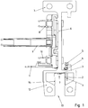
Figur 1 ist ein Querschnitt durch ein Schienenprofil mit integriertem Schlitzhohlleiter gezeigt, wobei mittels des Schlitzhohlleiters hochfrequente elektromagnetische Wellen zur Datenübertragung verwendbar sind. - In der
Figur 2 ist eine Schrägansicht auf die beiden am Boden des Schlitzhohlleiterabschnitts 12 angeordneten Kammreflektoren (2, 14) gezeigt. - In der
Figur 3 ist eine zurFigur 2 zugehörige Draufsicht gezeigt. - In der
Figur 4 ist eine Schrägansicht auf die beiden Kammreflektoren (2, 14) gezeigt. - In der
Figur 5 ist eine zurFigur 4 zugehörige Draufsicht gezeigt. - Wie in
Figur 1 gezeigt, weist die erfindungsgemäße Anlage eine Schiene auf, deren Profil einen Tragschienenabschnitt 7 aufweist und ein sich daran anschließender Wandabschnitt 6, an dessen vom Tragschienenabschnitt 7 abgewandtem Endbereich ein Hohlleitergehäuseabschnitt 12 angeordnet ist, der den Hohlleiterbereich des Schlitzhohlleiters umgibt. - Vorzugsweise ist die Schiene als Stranggussteil hergestellt.
- Der Tragschienenabschnitt 7 weist Abrollbereiche für Räder eines entlang der Schiene, also in Schienenrichtung, bewegbaren Schienenfahrzeugs auf.
- Von der Querrichtung her kommend sind Halteteile (8, 9, 10) für Hinleiter und Rückleiter eines langgestreckt in der Anlage verlegten Primärleitersystems am Wandabschnitt 6 befestigt. Das Schienenfahrzeug ist mit einer Sekundärwicklung ausgestattet, welche induktiv mit dem Primärleitersystem koppelbar ist und aus der auf diese Weise induktiv übertragbaren Leistung versorgbar ist.
- Anstatt dieser induktiven Versorgung ist bei einem anderen erfindungsgemäßen Ausführungsbeispiel auch eine Schleifversorgung am Wandabschnitt 6 anbringbar, wozu eine elektrische Schleifleitung am Wandabschnitt 6 befestigt wird.
- Wie in
Figur 1 gezeigt, ist am Schienenprofil ein Hohlleitergehäuseabschnitt 12 ausgebildet, so dass ein Schlitzhohlleiter im Schienenteil integriert ist. Mittels einer Antenne 1 ist an einer ersten Schienenposition ein Datensignal mittels elektromagnetischer Wellen in den Hohlleiter einkoppelbar und an einer anderen Schienenposition das Datensignal auskoppelbar mittels einer weiteren Antenne 1. - Das der Antenne 1 zugeführte Signal wird dabei über Koaxialkabel von außen herangeführt und dann über die Antenne 1 in den Hohlraum des Schlitzhohlleiters eingekoppelt beziehungsweise ausgekoppelt.
- Die Antenne 1 ist in den seitlichen Taschenbereichen des Hohlraums, also in Querrichtung, also quer zur Schienenrichtung, beabstandet von der mittigen Lage angeordnet. Somit ist eine am Schienenfahrzeug angeordnete, durch den Schlitzberiech des Schlitzhohlleiters in den Hohlraum des Schlitzhohlleiters hineinragende Antenne kollisionsfrei verfahrbar in Schienenrichtung.
- Mittels der Kammreflektoren (2, 14) ist eine Reflektierung der elektromagnetischen Wellen erreichbar, die vergleichbar ist mit der Reflexion an einer quer verlaufenden Wand. Trotzdem ist der Reflexionsbereich kollisionsfrei durchfahrbar vom Schienenfahrzeug mit seiner Antenne.
- Der Schlitzbereich ist also bis zum Bodenabschnitt 30 des Hohlraums des Schlitzhohlleiters frei.
- Der Hohlraum des Schlitzhohlleiters ist in Querrichtung weiter ausgedehnt als die Weite des Schlitzes 13 in Querrichtung. Entsprechend weist auch der Bodenabschnitt 50 eine entsprechend größere Ausdehnung auf in Querrichtung und es sind somit seitlich des in den Hohlraum sich senkrecht zum Bodenabschnitt 30 hin erstreckenden Schlitzbereiches Taschenbereiche gebildet.
- Die Antenne 1 und die Kammreflektoren (2, 14) sind in diesen Taschenbereichen angeordnet, wodurch ein kollisionsfreies Durchfahren des Schlitzbereiches für die Antenne des Schienenfahrzeugs ermöglicht ist.
- Dabei ist die Antenne 1 und ein erster Kammreflektor 2 in demselben Taschenbereich angeordnet. Im anderen Taschenbereich ist jeweils der andere Kammreflektor 14 angeordnet.
- Die Anzahl der in Schienenrichtung hintereinander regelmäßig voneinander beabstandet angeordneten Zinken des ersten Kammreflektors 2 ist geringer als die Anzahl der in Schienenrichtung hintereinander regelmäßig voneinander beabstandet angeordneten Zinken des zweiten Kammreflektors 14.
- Die Kammreflektoren (2, 14) sind als einstückiges Biegeteil, insbesondere Stanz-Biegeteil, ausgeführt, wie in den
Figuren 4 und5 gezeigt. - Der auf der gleichen Seite wie die Antenne 1 angeordnete Kammreflektor 14 weist in Schienenrichtung eine geringere Ausdehnung auf als der Kammreflektor 2, welcher auf der anderen Seite angeordnet ist, insbesondere also auf der anderen Seite der Mittellinie.
- Die einstückige Ausführung hat den weiteren Vorteil, dass die beiden Kammreflektoren (2, 14) in nur einem einzigen Arbeitsgang montierbar sind.
- Wie in
Figur 3 gezeigt, ist das einstückige Biegeteil mittels zwei Befestigungsschrauben 3 am Schienenprofilteil befestigt, wobei die beiden Schrauben 3 auf jeweils verschiedenen Seiten der Mittellinie angeordnet sind. - Auf diese Weise ist mittels der Bohrungen die Orientierung des Biegeteils eindeutig festlegbar und somit die Fehlerrate bei Montage verminderbar. Die Positionen der Bohrungen für die Schrauben 3 stellen also eine Codierung dar.
- Da die Datenübertragung in Schienenrichtung nur innerhalb eines begrenzten Bereichs stattfindet, sind zur Abgrenzung des Bereichs die Kammreflektoren 2 und 14 vorgesehen. Die Beabstandung der Zinken des jeweiligen Kammreflektors (2, 14) vermindern die Wirbelstromverluste.
- Die elektrische Leitung zur Antenne 1 führt durch eine durchgehende Bohrung im Schienenprofilteil ins Innere des Hohlraums des Schlitzhohlleiters, wo die Antenne 1 angeordnet ist. Im einfachsten Fall ist die elektrische Leitung als Antennenstab selbst ausgeführt, der an der äußeren Oberfläche angeschraubt ist und ins Innere des Hohlleiters hineinragt.
- Bei einem anderen erfindungsgemäßen Ausführungsbeispiel ist am Schlitzhohlleiterprofil ein Haltemittel ausgeformt oder vorgesehen, so dass ein Einhaken, Einklipsen oder anderweitigem Verbinden des Schlitzhohlleiterprofils an einem Schienenteil, insbesondere Führungsschienenteil zur Führung des Fahrzeugs, insbesondere eines auf dem Schienenteil verfahrbaren Schienenfahrzeugs, ermöglicht ist. Auf diese Weise sind verschiedenartige Schienenteile mit einem Schlitzhohlleiter ausstattbar. Nur die Verbindungsschnittstelle muss am Schienenteil ausgeprägt werden, also eine Schnittstelle zum Einhaken oder Einklipsen oder anderweitigen Verbinden.
- Bei einem weiteren erfindungsgemäßen Ausführungsbeispiel ist der Hohlleiter als Schlitzhohlleiterprofil ausgeführt, so dass er einerseits als Stranggussprofilteil, insbesondere Aluminium-Stranggussprofilteil, einfach und kostengünstig herstellbar ist und so dass andererseits eine Antenne eines in Profilrichtung sich bewegenden Fahrzeugs in den Schlitz hineinragen kann und daher Daten während der Bewegung austauschbar sind.
- Das Schlitzhohlleiterprofilteil ist bei diesem weiteren Ausführungsbeispiel daher vorzugsweise an dem Schienenteil mittels des am Schlitzhohlleiterprofilteil angeordneten Halteteils verbunden. Auch eine andere Verbindungsart ist ausführbar.
- Der Hohlraum des Schlitzhohlleiterprofilteils erstreckt sich wiederum in Profilrichtung gleichförmig. Quer zur Profilrichtung ist er symmetrisch zur Mitte aufgebaut. Der Schlitz, also die Öffnung, durch welche die Antenne des Fahrzeugs in den Hohlraum hineinragen darf, ist mittig angeordnet.
- Zur Anregung des H10 - Modes ragt eine Antenne 1 wiederum außermittig in den Hohlraum hinein. Der Hohlraum ist wiederum quer zur Profilrichtung und quer zum Schlitzbereich aufgeweitet, so dass er aus dem Schlitzbereich und zwei spiegelsymmetrisch zum Schlitzbereich ausgeformten Teilbereichen, also Taschenbereichen, zusammengesetzt ist. Die Antenne 1 ragt also in einen der Teilbereiche hinein. Die Antenne 1 wird wiederum von einem Steckverbinderteil für Koaxialkabel gehalten, das an der Außenseite des Schlitzhohlleiterprofils angeordnet ist. Dabei ragt die Antenne 1 durch eine Ausnehmung im Schlitzhohlleiterprofil hindurch. Mittels des Koaxialkabels leitet die Antenne 1 empfangen Signale an eine elektronische Schaltung weiter, die mittels des Koaxialkabels verbunden ist. Das Steckverbinderteil ist mittels Befestigungsschrauben am Schienenprofilteil befestigt.
- In Schienenrichtung hinter der Antenne 1 ist im Hohlraum in demjenigen Teilbereich, in welchen die Antenne hineinragt, wiederum ein erster Kammreflektor 2 angeordnet. Im anderen Teilbereich ist wiederum ein zweiter Kammreflektor 14 angeordnet, der jedoch in Profilrichtung versetzt angeordnet ist.
- Im Gegensatz zu den in den Figuren abgebildeten Kammreflektoren (2, 14) sind diese im genannten weiteren Ausführungsbeispiel gleichartig ausgeführt. Durch einen in Schienenrichtung gesehen vorgegebenen Versatz der beiden, ansonsten parallel zueinander ausgerichteten Kammreflektoren (2, 14) zueinander ist der H10-Mode der elektromagnetischen Wellenstrahlung im Schlitzhohlleiterraumbereich einfach und ohne Aufwand anregbar.
- Die Kammreflektoren 2 und 14 sind ebenfalls mittels Befestigungsschrauben 3 am Schlitzhohlleiterprofil schaubverbunden. Auch eine einstückige Ausführung der beiden Kammreflektoren durch wiederum ein Biegeteil, insbesondere ein Stanz-Biegeteil, ist ausführbar, so dass die Montage schnell und einfach ausführbar ist.
- Entweder ist das Schlitzhohlleiterprofil wiederum integriert ausgeführt oder alternativ ist am Schlitzhohlleiterprofil ein Haltemittel 7 ausgeformt oder vorgesehen, so dass ein Einhaken des Schlitzhohlleiterprofils an einem Schienenteil, insbesondere Führungsschienenteil zur Führung des Fahrzeugs, insbesondere eines auf dem Schienenteil verfahrbaren Schienenfahrzeugs, ermöglicht ist.
-
- 1
- Antenne
- 2
- erster Kammreflektor
- 3
- Befestigungsschrauben für Kammreflektor
- 4
- Distanzring
- 5
- Kappe
- 6
- Wandabschnitt
- 7
- Tragschienenabschnitt
- 8
- Halteteil für Hinleiter
- 9
- Halteteil für Rückleiter
- 10
- Halteteil für Hinleiter
- 11
- Barcodehalterung
- 12
- Hohlleitergehäuseabschnitt
- 13
- Schlitz
- 14
- zweiter Kammreflektor
- 30
- Bodenabschnitt des Hohlraums des Schlitzhohlleiters
Claims (11)
- Anordnung zur Datenübertragung zwischen einem ersten Anlagenteil und einem relativ zum ersten Anlagenteil verfahrbaren Mobilteil, wobei das Mobilteil ein auf einer Schiene des ersten Anlagenteils verfahrbares Fahrzeug ist,
wobei der erste Anlagenteil einen Schlitzhohlleiter aufweist, wobei sich der Schlitz (13) in Fahrtrichtung erstreckt,
wobei eine am Mobilteil angeordnete Antenne (1) durch den Schlitz (13) in den Hohlleiterbereich des Schlitzhohlleiters hineinragt,
wobei der Querschnitt des Hohlleiterbereichs symmetrisch zum Schlitzbereich ausgeführt ist, wobei der Hohlleiterbereich aus dem Schlitzbereich und zwei, beidseitig des Schlitzbereiches angeordneten Teilbereichen gebildet ist,
wobei eine Antenne (1) des ersten Anlagenteils quer zur Fahrtrichtung gesehen außermittig, in den Hohlleiterbereich des Schlitzhohlleiters hineinragt, also in einen der Teilbereiche,
wobei in jedem Teilbereich ein aus Kupfer-haltigem Material ausgeführter Kammreflektor (2, 14) angeordnet ist,
wobei die Kammreflektoren (2, 14) miteinander einstückig ausgeführt sind,
wobei die Kammreflektoren (2, 14) aus einem Biegeteil ausgeführt sind,
wobei das Biegeteil mittels Schrauben mit dem Schlitzhohlleiterprofil verbunden ist, deren Schraubenköpfe in den Schlitzbereich hineinragen,
wobei die Kammreflektoren (2, 14) in Schienenrichtung oder Fahrtrichtung zueinander einen Versatz aufweisen, und der H10 Mode der elektromagnetischen Wellen im Hohlleiter anregbar ist. - Anordnung nach mindestens einem der vorangegangenen Ansprüche,
dadurch gekennzeichnet, dass
in einem ersten Bereich die Antenne (1) und ein erster Kammreflektor (2) in einem ersten Teilbereich angeordnet sind, wobei der zweite Kammreflektor (14) in dem anderen Teilbereich angeordnet ist,
insbesondere wobei in einem in Schienenrichtung davon beabstandeten anderen Bereich
eine weitere Antenne (1) und ein weiterer erster Kammreflektor (2) in dem ersten Teilbereich angeordnet sind und ein weiterer Kammreflektor (14) in dem anderen Teilbereich angeordnet ist. - Anordnung nach mindestens einem der vorangegangenen Ansprüche,
dadurch gekennzeichnet, dass
eine erste in den Schlitzhohlleiter eingebrachte Bohrung zur Aufnahme einer Schraube, mit welcher das Biegeteil mit dem Schitzhohlleiterprofil schraubverbunden ist, einen Versatz zur im Schlitzbereich mittigen Lage aufweist
und
eine zweite in den Schlitzhohlleiter eingebrachte Bohrung zur Aufnahme einer zweiten Schraube, mit welcher das Biegeteil mit dem Schitzhohlleiterprofil zusätzlich schraubverbunden ist, einen gegengerichteten Versatz zur im Schlitzbereich mittigen Lage aufweist, insbesondere also auf der anderen Seite zur mittigen Lage angeordnet ist. - Anordnung nach mindestens einem der vorangegangenen Ansprüche,
dadurch gekennzeichnet, dass die Schiene ein Profilschienenteil ist, insbesondere gefertigt als Aluminium-Strangguss-Profilteil. - Anordnung nach mindestens einem der vorangegangenen Ansprüche,
dadurch gekennzeichnet, dass
der Schlitzhohlleiter aus einem Stranggussteil gefertigt ist, insbesondere Aluminium-Strangguss, insbesondere zumindest teilweise eloxierter Aluminium-Strangguss. - Anordnung nach mindestens einem der vorangegangenen Ansprüche,
dadurch gekennzeichnet, dass
die Kammreflektoren (2, 14) gleichartig oder alternativ in Schienenrichtung beziehungswiese Fahrtrichtung verschieden lang ausgeführt sind. - Anordnung nach mindestens einem der vorangegangenen Ansprüche,
dadurch gekennzeichnet, dass
die Kammreflektoren (2, 14) jeweils regelmäßig voneinander beabstandete Zinken aufweisen, die in Fahrtrichtung aufgereiht hintereinander angeordnet sind, insbesondere zur Verringerung der Wirbelstromverluste. - Anordnung nach mindestens einem der vorangegangenen Ansprüche,
dadurch gekennzeichnet, dass
die Kammreflektoren (2, 14) jeweils einen Grundkörper aufweisen, an welchem die Zinken einstückig ausgeformt oder angeformt sind, insbesondere wobei die Zinken jeweils quaderförmig oder zylinderförmig ausgeführt sind. - Anordnung nach mindestens einem der vorangegangenen Ansprüche,
dadurch gekennzeichnet, dass
die stationär angeordnete Antenne (1) von einem Steckverbinderteil gehalten ist, mit welchem ein Koaxialsteckverbinderteil steckverbindbar ist,
insbesondere wobei das Steckverbinderteil schraubverbunden ist mit dem Schlitzhohlleiterteil. - Anordnung nach mindestens einem der vorangegangenen Ansprüche,
dadurch gekennzeichnet, dass
die Kammreflektoren (2, 14) seitlich des Schlitzbereichs, insbesondere also in den Teilbereichen, angeordnet sind, insbesondere also einen zur mittigen Position nicht verschwindenden Versatz aufweisen, insbesondere also quer zu Schienenrichtung oder Fahrtrichtung außermittig angeordnet sind,
und/oder dass
die Kammreflektoren (2, 14) schraubverbunden sind mit dem Schlitzhohlleiterteil. - Anordnung nach mindestens einem der vorangegangenen Ansprüche,
dadurch gekennzeichnet, dass
der Schlitzhohlleiter an der Schiene formschlüssig verbunden ist, insbesondere eingehakt oder eingeklipst ist,
oder dass der Schlitzhohlleiter mit der Schiene einstückig ausgeführt ist, insbesondere als Stranggussprofilteil, insbesondere als Aluminium-Stranggussprofilteil.
Applications Claiming Priority (2)
| Application Number | Priority Date | Filing Date | Title |
|---|---|---|---|
| DE102012002718.4A DE102012002718B4 (de) | 2012-02-14 | 2012-02-14 | Anordnung zur Datenübertragung zwischen einem ersten Anlagenteil und einem relativ zum ersten Anlagenteil verfahrbaren Mobilteil |
| PCT/EP2013/000087 WO2013120572A1 (de) | 2012-02-14 | 2013-01-14 | Anordnung zur datenübertragung zwischen einem ersten anlagenteil, insbesondere stationärer anlagenteil, und einem relativ zum ersten anlagenteil verfahrbaren mobilteil |
Publications (2)
| Publication Number | Publication Date |
|---|---|
| EP2815460A1 EP2815460A1 (de) | 2014-12-24 |
| EP2815460B1 true EP2815460B1 (de) | 2019-05-08 |
Family
ID=47598781
Family Applications (1)
| Application Number | Title | Priority Date | Filing Date |
|---|---|---|---|
| EP13700844.7A Active EP2815460B1 (de) | 2012-02-14 | 2013-01-14 | Anordnung zur datenübertragung zwischen einem ersten anlagenteil, insbesondere stationärer anlagenteil, und einem relativ zum ersten anlagenteil verfahrbaren mobilteil |
Country Status (3)
| Country | Link |
|---|---|
| EP (1) | EP2815460B1 (de) |
| DE (1) | DE102012002718B4 (de) |
| WO (1) | WO2013120572A1 (de) |
Families Citing this family (4)
| Publication number | Priority date | Publication date | Assignee | Title |
|---|---|---|---|---|
| DE102019002171A1 (de) | 2018-04-16 | 2019-10-17 | Sew-Eurodrive Gmbh & Co Kg | System mit Profilteil |
| DE102019002167A1 (de) | 2018-04-16 | 2019-10-17 | Sew-Eurodrive Gmbh & Co Kg | System mit Profilteil |
| WO2020239263A1 (de) * | 2019-05-29 | 2020-12-03 | Sew-Eurodrive Gmbh & Co. Kg | System, insbesondere anlage, mit einem mobilteil und einem einen schirm aufnehmenden aufnahmeteil |
| DE102022000661A1 (de) | 2021-03-12 | 2022-09-15 | Sew-Eurodrive Gmbh & Co Kg | Verfahren zum Betreiben eines Kommunikationssystems und Kommunikationssystem |
Family Cites Families (3)
| Publication number | Priority date | Publication date | Assignee | Title |
|---|---|---|---|---|
| DE102004008571B4 (de) * | 2004-02-19 | 2012-09-06 | Paul Vahle Gmbh & Co. Kg | Tragschienenprofil mit integriertem Schlitzhohlleiter zur Datenübertragung |
| DE102009052871B9 (de) * | 2009-09-08 | 2020-10-15 | Sew-Eurodrive Gmbh & Co Kg | Vorrichtung zur Energie- und/oder Datenübertragung |
| EP2490926B1 (de) * | 2009-10-19 | 2016-03-23 | SEW-EURODRIVE GmbH & Co. KG | Anlage mit schienengeführtem fahrzeug |
-
2012
- 2012-02-14 DE DE102012002718.4A patent/DE102012002718B4/de active Active
-
2013
- 2013-01-14 EP EP13700844.7A patent/EP2815460B1/de active Active
- 2013-01-14 WO PCT/EP2013/000087 patent/WO2013120572A1/de not_active Ceased
Non-Patent Citations (1)
| Title |
|---|
| None * |
Also Published As
| Publication number | Publication date |
|---|---|
| WO2013120572A1 (de) | 2013-08-22 |
| DE102012002718A1 (de) | 2013-08-14 |
| EP2815460A1 (de) | 2014-12-24 |
| DE102012002718B4 (de) | 2015-04-02 |
Similar Documents
| Publication | Publication Date | Title |
|---|---|---|
| EP2737576B1 (de) | Anordnung zur datenübertragung zwischen einem ersten anlagenteil, insbesondere stationärer anlagenteil, und einem relativ zum ersten anlagenteil verfahrbaren mobilteil | |
| DE102009052871B4 (de) | Vorrichtung zur Energie- und/oder Datenübertragung | |
| DE102004008571B4 (de) | Tragschienenprofil mit integriertem Schlitzhohlleiter zur Datenübertragung | |
| EP2815460B1 (de) | Anordnung zur datenübertragung zwischen einem ersten anlagenteil, insbesondere stationärer anlagenteil, und einem relativ zum ersten anlagenteil verfahrbaren mobilteil | |
| EP2812946B1 (de) | Anlage mit einem schlitzhohlleiter zur datenübertragung | |
| EP1232539A1 (de) | Kurzes kontaktelement zwischen gehäuseteilen | |
| DE10119910C1 (de) | Gehäuse | |
| DE102009061067B4 (de) | Anordnung zur hochfrequenten Signaleinspeisung über ein Koaxialkabel in einen Schlitzhohlleiter und Anlage mit einer Anordnung zur hochfrequenten Signaleinspeisung | |
| EP1969670A1 (de) | Vorrichtung zum senden und/oder empfangen elektromagnetischer hf-signale | |
| DE102011119375B4 (de) | Haltevorrichtung zur Aufnahme von Leitern, Haltesystem und Anlage | |
| DE102015103983A1 (de) | Schlitzhohlleiter mit geringer Breite | |
| DE10316385A1 (de) | Kontaktadapter für die Kontaktierung einer Antennenstruktur eines Fahrzeuges | |
| DE102012002090A1 (de) | Transportsystem | |
| WO2012159618A1 (de) | Rfid-transponder mit abgebogener schlitzantenne | |
| EP2525028A9 (de) | Bauteil für ein Fahrzeug | |
| EP4063723A1 (de) | Leuchte mit mechanischer befestigung in länglicher tragschiene | |
| DE4211923C1 (de) | ||
| DE102004049982B4 (de) | Einschienenhängebahn zur berührungslosen Energieübertragung mit einem entlang einem Schienenprofil bewegbaren Teil | |
| DE102019002167A1 (de) | System mit Profilteil | |
| DE102019002171A1 (de) | System mit Profilteil | |
| EP2233894A2 (de) | Bewegungsvorrichtung mit Wellenleiter zur Positionsbestimmung | |
| DE102013009620B4 (de) | System zur kontaktlosen Energieübertragung von einem Primärleitersystem an ein Mobilteil | |
| EP0749104A1 (de) | Vorrichtung zur Übertragung des von einer innerhalb eines Gehäuses angeordneten Lichtquelle abgestrahlten Lichtes nach aussen | |
| EP3211296A1 (de) | Invertierte led-leiterkarte |
Legal Events
| Date | Code | Title | Description |
|---|---|---|---|
| PUAI | Public reference made under article 153(3) epc to a published international application that has entered the european phase |
Free format text: ORIGINAL CODE: 0009012 |
|
| 17P | Request for examination filed |
Effective date: 20140915 |
|
| AK | Designated contracting states |
Kind code of ref document: A1 Designated state(s): AL AT BE BG CH CY CZ DE DK EE ES FI FR GB GR HR HU IE IS IT LI LT LU LV MC MK MT NL NO PL PT RO RS SE SI SK SM TR |
|
| AX | Request for extension of the european patent |
Extension state: BA ME |
|
| DAX | Request for extension of the european patent (deleted) | ||
| GRAP | Despatch of communication of intention to grant a patent |
Free format text: ORIGINAL CODE: EPIDOSNIGR1 |
|
| STAA | Information on the status of an ep patent application or granted ep patent |
Free format text: STATUS: GRANT OF PATENT IS INTENDED |
|
| INTG | Intention to grant announced |
Effective date: 20181217 |
|
| GRAS | Grant fee paid |
Free format text: ORIGINAL CODE: EPIDOSNIGR3 |
|
| GRAA | (expected) grant |
Free format text: ORIGINAL CODE: 0009210 |
|
| STAA | Information on the status of an ep patent application or granted ep patent |
Free format text: STATUS: THE PATENT HAS BEEN GRANTED |
|
| AK | Designated contracting states |
Kind code of ref document: B1 Designated state(s): AL AT BE BG CH CY CZ DE DK EE ES FI FR GB GR HR HU IE IS IT LI LT LU LV MC MK MT NL NO PL PT RO RS SE SI SK SM TR |
|
| REG | Reference to a national code |
Ref country code: GB Ref legal event code: FG4D Free format text: NOT ENGLISH |
|
| REG | Reference to a national code |
Ref country code: CH Ref legal event code: EP Ref country code: AT Ref legal event code: REF Ref document number: 1131684 Country of ref document: AT Kind code of ref document: T Effective date: 20190515 |
|
| REG | Reference to a national code |
Ref country code: DE Ref legal event code: R096 Ref document number: 502013012775 Country of ref document: DE Ref country code: IE Ref legal event code: FG4D Free format text: LANGUAGE OF EP DOCUMENT: GERMAN |
|
| REG | Reference to a national code |
Ref country code: NL Ref legal event code: MP Effective date: 20190508 |
|
| REG | Reference to a national code |
Ref country code: LT Ref legal event code: MG4D |
|
| PG25 | Lapsed in a contracting state [announced via postgrant information from national office to epo] |
Ref country code: HR Free format text: LAPSE BECAUSE OF FAILURE TO SUBMIT A TRANSLATION OF THE DESCRIPTION OR TO PAY THE FEE WITHIN THE PRESCRIBED TIME-LIMIT Effective date: 20190508 Ref country code: NL Free format text: LAPSE BECAUSE OF FAILURE TO SUBMIT A TRANSLATION OF THE DESCRIPTION OR TO PAY THE FEE WITHIN THE PRESCRIBED TIME-LIMIT Effective date: 20190508 Ref country code: SE Free format text: LAPSE BECAUSE OF FAILURE TO SUBMIT A TRANSLATION OF THE DESCRIPTION OR TO PAY THE FEE WITHIN THE PRESCRIBED TIME-LIMIT Effective date: 20190508 Ref country code: PT Free format text: LAPSE BECAUSE OF FAILURE TO SUBMIT A TRANSLATION OF THE DESCRIPTION OR TO PAY THE FEE WITHIN THE PRESCRIBED TIME-LIMIT Effective date: 20190908 Ref country code: AL Free format text: LAPSE BECAUSE OF FAILURE TO SUBMIT A TRANSLATION OF THE DESCRIPTION OR TO PAY THE FEE WITHIN THE PRESCRIBED TIME-LIMIT Effective date: 20190508 Ref country code: FI Free format text: LAPSE BECAUSE OF FAILURE TO SUBMIT A TRANSLATION OF THE DESCRIPTION OR TO PAY THE FEE WITHIN THE PRESCRIBED TIME-LIMIT Effective date: 20190508 Ref country code: NO Free format text: LAPSE BECAUSE OF FAILURE TO SUBMIT A TRANSLATION OF THE DESCRIPTION OR TO PAY THE FEE WITHIN THE PRESCRIBED TIME-LIMIT Effective date: 20190808 Ref country code: ES Free format text: LAPSE BECAUSE OF FAILURE TO SUBMIT A TRANSLATION OF THE DESCRIPTION OR TO PAY THE FEE WITHIN THE PRESCRIBED TIME-LIMIT Effective date: 20190508 Ref country code: LT Free format text: LAPSE BECAUSE OF FAILURE TO SUBMIT A TRANSLATION OF THE DESCRIPTION OR TO PAY THE FEE WITHIN THE PRESCRIBED TIME-LIMIT Effective date: 20190508 |
|
| PG25 | Lapsed in a contracting state [announced via postgrant information from national office to epo] |
Ref country code: GR Free format text: LAPSE BECAUSE OF FAILURE TO SUBMIT A TRANSLATION OF THE DESCRIPTION OR TO PAY THE FEE WITHIN THE PRESCRIBED TIME-LIMIT Effective date: 20190809 Ref country code: BG Free format text: LAPSE BECAUSE OF FAILURE TO SUBMIT A TRANSLATION OF THE DESCRIPTION OR TO PAY THE FEE WITHIN THE PRESCRIBED TIME-LIMIT Effective date: 20190808 Ref country code: RS Free format text: LAPSE BECAUSE OF FAILURE TO SUBMIT A TRANSLATION OF THE DESCRIPTION OR TO PAY THE FEE WITHIN THE PRESCRIBED TIME-LIMIT Effective date: 20190508 Ref country code: LV Free format text: LAPSE BECAUSE OF FAILURE TO SUBMIT A TRANSLATION OF THE DESCRIPTION OR TO PAY THE FEE WITHIN THE PRESCRIBED TIME-LIMIT Effective date: 20190508 |
|
| PG25 | Lapsed in a contracting state [announced via postgrant information from national office to epo] |
Ref country code: EE Free format text: LAPSE BECAUSE OF FAILURE TO SUBMIT A TRANSLATION OF THE DESCRIPTION OR TO PAY THE FEE WITHIN THE PRESCRIBED TIME-LIMIT Effective date: 20190508 Ref country code: DK Free format text: LAPSE BECAUSE OF FAILURE TO SUBMIT A TRANSLATION OF THE DESCRIPTION OR TO PAY THE FEE WITHIN THE PRESCRIBED TIME-LIMIT Effective date: 20190508 Ref country code: RO Free format text: LAPSE BECAUSE OF FAILURE TO SUBMIT A TRANSLATION OF THE DESCRIPTION OR TO PAY THE FEE WITHIN THE PRESCRIBED TIME-LIMIT Effective date: 20190508 Ref country code: CZ Free format text: LAPSE BECAUSE OF FAILURE TO SUBMIT A TRANSLATION OF THE DESCRIPTION OR TO PAY THE FEE WITHIN THE PRESCRIBED TIME-LIMIT Effective date: 20190508 Ref country code: SK Free format text: LAPSE BECAUSE OF FAILURE TO SUBMIT A TRANSLATION OF THE DESCRIPTION OR TO PAY THE FEE WITHIN THE PRESCRIBED TIME-LIMIT Effective date: 20190508 |
|
| REG | Reference to a national code |
Ref country code: DE Ref legal event code: R097 Ref document number: 502013012775 Country of ref document: DE |
|
| PG25 | Lapsed in a contracting state [announced via postgrant information from national office to epo] |
Ref country code: SM Free format text: LAPSE BECAUSE OF FAILURE TO SUBMIT A TRANSLATION OF THE DESCRIPTION OR TO PAY THE FEE WITHIN THE PRESCRIBED TIME-LIMIT Effective date: 20190508 Ref country code: IT Free format text: LAPSE BECAUSE OF FAILURE TO SUBMIT A TRANSLATION OF THE DESCRIPTION OR TO PAY THE FEE WITHIN THE PRESCRIBED TIME-LIMIT Effective date: 20190508 |
|
| PLBE | No opposition filed within time limit |
Free format text: ORIGINAL CODE: 0009261 |
|
| STAA | Information on the status of an ep patent application or granted ep patent |
Free format text: STATUS: NO OPPOSITION FILED WITHIN TIME LIMIT |
|
| PG25 | Lapsed in a contracting state [announced via postgrant information from national office to epo] |
Ref country code: TR Free format text: LAPSE BECAUSE OF FAILURE TO SUBMIT A TRANSLATION OF THE DESCRIPTION OR TO PAY THE FEE WITHIN THE PRESCRIBED TIME-LIMIT Effective date: 20190508 |
|
| 26N | No opposition filed |
Effective date: 20200211 |
|
| PG25 | Lapsed in a contracting state [announced via postgrant information from national office to epo] |
Ref country code: PL Free format text: LAPSE BECAUSE OF FAILURE TO SUBMIT A TRANSLATION OF THE DESCRIPTION OR TO PAY THE FEE WITHIN THE PRESCRIBED TIME-LIMIT Effective date: 20190508 |
|
| PG25 | Lapsed in a contracting state [announced via postgrant information from national office to epo] |
Ref country code: SI Free format text: LAPSE BECAUSE OF FAILURE TO SUBMIT A TRANSLATION OF THE DESCRIPTION OR TO PAY THE FEE WITHIN THE PRESCRIBED TIME-LIMIT Effective date: 20190508 |
|
| PG25 | Lapsed in a contracting state [announced via postgrant information from national office to epo] |
Ref country code: MC Free format text: LAPSE BECAUSE OF FAILURE TO SUBMIT A TRANSLATION OF THE DESCRIPTION OR TO PAY THE FEE WITHIN THE PRESCRIBED TIME-LIMIT Effective date: 20190508 |
|
| REG | Reference to a national code |
Ref country code: CH Ref legal event code: PL |
|
| REG | Reference to a national code |
Ref country code: BE Ref legal event code: MM Effective date: 20200131 |
|
| PG25 | Lapsed in a contracting state [announced via postgrant information from national office to epo] |
Ref country code: LU Free format text: LAPSE BECAUSE OF NON-PAYMENT OF DUE FEES Effective date: 20200114 |
|
| PG25 | Lapsed in a contracting state [announced via postgrant information from national office to epo] |
Ref country code: BE Free format text: LAPSE BECAUSE OF NON-PAYMENT OF DUE FEES Effective date: 20200131 Ref country code: CH Free format text: LAPSE BECAUSE OF NON-PAYMENT OF DUE FEES Effective date: 20200131 Ref country code: LI Free format text: LAPSE BECAUSE OF NON-PAYMENT OF DUE FEES Effective date: 20200131 |
|
| PG25 | Lapsed in a contracting state [announced via postgrant information from national office to epo] |
Ref country code: IE Free format text: LAPSE BECAUSE OF NON-PAYMENT OF DUE FEES Effective date: 20200114 |
|
| REG | Reference to a national code |
Ref country code: AT Ref legal event code: MM01 Ref document number: 1131684 Country of ref document: AT Kind code of ref document: T Effective date: 20200114 |
|
| PG25 | Lapsed in a contracting state [announced via postgrant information from national office to epo] |
Ref country code: AT Free format text: LAPSE BECAUSE OF NON-PAYMENT OF DUE FEES Effective date: 20200114 |
|
| PG25 | Lapsed in a contracting state [announced via postgrant information from national office to epo] |
Ref country code: MT Free format text: LAPSE BECAUSE OF FAILURE TO SUBMIT A TRANSLATION OF THE DESCRIPTION OR TO PAY THE FEE WITHIN THE PRESCRIBED TIME-LIMIT Effective date: 20190508 Ref country code: CY Free format text: LAPSE BECAUSE OF FAILURE TO SUBMIT A TRANSLATION OF THE DESCRIPTION OR TO PAY THE FEE WITHIN THE PRESCRIBED TIME-LIMIT Effective date: 20190508 |
|
| PG25 | Lapsed in a contracting state [announced via postgrant information from national office to epo] |
Ref country code: MK Free format text: LAPSE BECAUSE OF FAILURE TO SUBMIT A TRANSLATION OF THE DESCRIPTION OR TO PAY THE FEE WITHIN THE PRESCRIBED TIME-LIMIT Effective date: 20190508 Ref country code: IS Free format text: LAPSE BECAUSE OF FAILURE TO SUBMIT A TRANSLATION OF THE DESCRIPTION OR TO PAY THE FEE WITHIN THE PRESCRIBED TIME-LIMIT Effective date: 20190908 |
|
| PGFP | Annual fee paid to national office [announced via postgrant information from national office to epo] |
Ref country code: GB Payment date: 20251204 Year of fee payment: 14 |
|
| PGFP | Annual fee paid to national office [announced via postgrant information from national office to epo] |
Ref country code: FR Payment date: 20251208 Year of fee payment: 14 |
|
| PGFP | Annual fee paid to national office [announced via postgrant information from national office to epo] |
Ref country code: DE Payment date: 20260131 Year of fee payment: 14 |