EP2815460B1 - Ensemble de transmission de données entre une première partie d'installation, en particulier fixe, et une partie mobile par rapport à la première partie d'installation - Google Patents
Ensemble de transmission de données entre une première partie d'installation, en particulier fixe, et une partie mobile par rapport à la première partie d'installation Download PDFInfo
- Publication number
- EP2815460B1 EP2815460B1 EP13700844.7A EP13700844A EP2815460B1 EP 2815460 B1 EP2815460 B1 EP 2815460B1 EP 13700844 A EP13700844 A EP 13700844A EP 2815460 B1 EP2815460 B1 EP 2815460B1
- Authority
- EP
- European Patent Office
- Prior art keywords
- rail
- waveguide
- comb
- slot
- region
- Prior art date
- Legal status (The legal status is an assumption and is not a legal conclusion. Google has not performed a legal analysis and makes no representation as to the accuracy of the status listed.)
- Active
Links
Images


Classifications
-
- H—ELECTRICITY
- H01—ELECTRIC ELEMENTS
- H01Q—ANTENNAS, i.e. RADIO AERIALS
- H01Q13/00—Waveguide horns or mouths; Slot antennas; Leaky-waveguide antennas; Equivalent structures causing radiation along the transmission path of a guided wave
- H01Q13/20—Non-resonant leaky-waveguide or transmission-line antennas; Equivalent structures causing radiation along the transmission path of a guided wave
- H01Q13/22—Longitudinal slot in boundary wall of waveguide or transmission line
-
- H—ELECTRICITY
- H04—ELECTRIC COMMUNICATION TECHNIQUE
- H04B—TRANSMISSION
- H04B5/00—Near-field transmission systems, e.g. inductive or capacitive transmission systems
- H04B5/20—Near-field transmission systems, e.g. inductive or capacitive transmission systems characterised by the transmission technique; characterised by the transmission medium
- H04B5/24—Inductive coupling
-
- H—ELECTRICITY
- H01—ELECTRIC ELEMENTS
- H01P—WAVEGUIDES; RESONATORS, LINES, OR OTHER DEVICES OF THE WAVEGUIDE TYPE
- H01P3/00—Waveguides; Transmission lines of the waveguide type
- H01P3/12—Hollow waveguides
-
- H—ELECTRICITY
- H01—ELECTRIC ELEMENTS
- H01P—WAVEGUIDES; RESONATORS, LINES, OR OTHER DEVICES OF THE WAVEGUIDE TYPE
- H01P5/00—Coupling devices of the waveguide type
- H01P5/08—Coupling devices of the waveguide type for linking dissimilar lines or devices
- H01P5/10—Coupling devices of the waveguide type for linking dissimilar lines or devices for coupling balanced lines or devices with unbalanced lines or devices
- H01P5/103—Hollow-waveguide/coaxial-line transitions
-
- H—ELECTRICITY
- H04—ELECTRIC COMMUNICATION TECHNIQUE
- H04B—TRANSMISSION
- H04B5/00—Near-field transmission systems, e.g. inductive or capacitive transmission systems
- H04B5/20—Near-field transmission systems, e.g. inductive or capacitive transmission systems characterised by the transmission technique; characterised by the transmission medium
- H04B5/28—Near-field transmission systems, e.g. inductive or capacitive transmission systems characterised by the transmission technique; characterised by the transmission medium using the near field of leaky cables, e.g. of leaky coaxial cables
-
- H—ELECTRICITY
- H04—ELECTRIC COMMUNICATION TECHNIQUE
- H04B—TRANSMISSION
- H04B5/00—Near-field transmission systems, e.g. inductive or capacitive transmission systems
- H04B5/40—Near-field transmission systems, e.g. inductive or capacitive transmission systems characterised by components specially adapted for near-field transmission
- H04B5/43—Antennas
Definitions
- the invention relates to an arrangement for data transmission between a first part of the plant, in particular stationary part of the plant, and a movable part movable relative to the first part of the plant.
- the invention is therefore based on the object to achieve an improved data transmission in the data transmission in a system, in particular an improved signal-to-noise ratio.
- the object is achieved in the arrangement for data transmission according to the features specified in claim 1.
- the mobile part is a vehicle that can travel on a rail of the first part of the installation
- the first piece of equipment comprises a slot waveguide, the slot extending in the direction of travel, wherein an antenna disposed on the handset protrudes through the slot in the waveguide region of the slot waveguide, wherein the cross-section, in particular transversely to the direction of travel, of the waveguide region is designed symmetrically to the slot region, the waveguide region being formed from the slot region and two partial regions, in particular lateral regions, arranged on both sides of the slot region, wherein an antenna of the first part of the plant, in particular a stationary antenna, seen transversely to the direction of travel eccentrically protrudes into the waveguide region of the slot waveguide, in particular so in one of the subregions, wherein in each subarea a comb
- the advantage here is that a simple assembly is executable and the relative positioning of the comb reflectors is performed easily and without any special effort.
- a high bandwidth is achievable, not the same length in the rail direction execution of the two comb reflectors.
- the comb reflectors of the slot waveguide is designed to be reflective at the corresponding position for electromagnetic waves, so shut off. In this way, therefore, with respect to the data transmission independently operating rail sections can be produced. In each section, then, independently of one another, different data signals can be transmitted between the vehicle and a respective stationary electronic unit. Thus, the vehicle exchanges information with various stationary units depending on the position in the rail system.
- the comb reflectors are made of a bent part, in particular of a stamped and bent part.
- the advantage here is that a simple production by bending a sheet and / or laser cutting and / or punching is possible.
- the bent part are connected by means of screws with the slot waveguide profile, the screw heads protrude into the slot area.
- the advantage here is that the operation of the screws and the previously necessary drilling of the holes can be introduced through the insertion of the drilling tool through the slot area. In the production, therefore, a very long drill is used, which extends through the slot area in the bottom portion of the slot waveguide.
- the space for the drilling tool, in particular drill is not limited in the other direction during processing by the slot waveguide profile or rail part. Thus, a simple introduction of the holes is possible and also easy attachment of the comb reflectors on the rail part.
- the antenna and a first comb reflector are arranged in a first region in a first region, wherein the second comb reflector is arranged in the other region,
- a further antenna and a further first comb reflector are arranged in the first subregion and a further comb reflector is arranged in the other subregion.
- a first introduced into the slot waveguide bore for receiving a screw, with which the bending part is screw-connected to the Schitzhohlleiterprofil, an offset to the central area in the slot area and a second introduced into the slot waveguide bore has for receiving a second screw, with which the bending part is additionally screw-connected with the Schitzhohlleiterprofil, a counter-offset to the central region in the slot area, in particular so on the other side is arranged to the central position.
- the comb reflectors have an offset in the rail direction or direction to each other.
- the advantage here is that the H10 mode of the electromagnetic waves in the waveguide is particularly effective excitable. Thus, a particularly low-error data transmission can be achieved and noise can be reduced, thus improving the signal-to-noise ratio.
- the mobile part is a movable on a rail of the first part of the system vehicle, in particular wherein the rail extends in the direction of travel and the slot waveguide is laid parallel to the rail, in particular wherein the rail is a profiled rail part, in particular manufactured as aluminum extruded profile part.
- the slot waveguide is made of a continuous casting, in particular aluminum continuous casting, in particular at least partially anodized aluminum continuous casting.
- the comb reflectors are identically or alternatively running in the rail direction or direction of travel direction of different lengths .
- the advantage here is that a simple production is possible with a small number of parts.
- the comb reflectors each have regularly spaced tines, which are lined up in the direction of travel one behind the other.
- the advantage here is that a vibration mode of the electromagnetic waves is particularly effective excitable, so other vibration modes are excited as little as possible.
- the comb reflectors each have a base body on which the tines are integrally formed or formed, in particular wherein the tines are each designed cuboid or cylindrical.
- comb reflectors are made of copper-containing material, in particular as a stamped and bent part.
- the advantage here is that a low absorption occurs and a simple production is possible.
- the stationarily arranged antenna is held by a connector part with which a coaxial connector part is plugged,
- the connector part is screw-connected to the slot waveguide part.
- the advantage here is that a simple connection technology is used and the electrical connector is used to hold.
- the comb reflectors are arranged laterally of the slot area, ie in particular in the partial areas.
- the advantage here is that the antenna of the vehicle is undisturbed in the direction of travel in the slot movable.
- the comb reflectors are screw-connected to the slot waveguide part.
- the advantage here is that a simple connection technique is used.
- the slot waveguide is positively connected to the rail, in particular hooked or clipped, or that the slot waveguide is designed in one piece with the rail, in particular as a continuous cast profile part, in particular as an aluminum extruded section part.
- the advantage here is that a simple cost-effective production is possible, the parallelism of the rail and the slot of the slot waveguide is error-free maintainable.
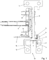
- the system according to the invention has a rail whose profile has a carrier rail section 7 and a wall section 6 adjoining thereto, at whose end region remote from the carrier rail section 7 a waveguide housing section 12 is arranged which surrounds the waveguide region of the slot waveguide.
- the rail is manufactured as a continuous casting.
- the support rail section 7 has Abroll Schemee for wheels along the rail, so in the rail direction, movable rail vehicle.
- the rail vehicle is equipped with a secondary winding, which is inductively coupled to the primary conductor system and from the inductively transferable in this way power can be supplied.
- this inductive supply is in another embodiment of the invention also an abrasive supply to the wall portion 6 attachable, for which purpose an electrical conductor line is attached to the wall portion 6.
- a waveguide housing portion 12 is formed on the rail profile, so that a slot waveguide is integrated in the rail part.
- a data signal can be coupled into the waveguide by means of electromagnetic waves at a first rail position and the data signal can be decoupled at another rail position by means of a further antenna 1.
- the signal supplied to the antenna 1 is thereby introduced via coaxial cable from the outside and then coupled via the antenna 1 into the cavity of the slot waveguide or coupled out.
- the antenna 1 is arranged in the lateral pocket regions of the cavity, ie in the transverse direction, ie transversely to the rail direction, at a distance from the central layer.
- a arranged on the rail vehicle, projecting through the Schlitzberiech of the slot waveguide in the cavity of the slot waveguide antenna is collision-free movable in the rail direction.
- comb reflectors (2, 14) By means of the comb reflectors (2, 14) a reflection of the electromagnetic waves can be achieved, which is comparable to the reflection on a transverse wall. Nevertheless, the reflection range is collision-free traversable by the rail vehicle with its antenna.
- the slot area is thus free up to the bottom portion 30 of the cavity of the slot waveguide.
- the cavity of the slot waveguide is wider in the transverse direction than the width of the slot 13 in the transverse direction.
- the bottom section 50 also has a correspondingly greater extent in the transverse direction, and pocket regions are thus formed laterally of the slot region extending into the cavity perpendicular to the bottom section 30.
- the antenna 1 and the comb reflectors (2, 14) are arranged in these pocket areas, whereby a collision-free passage through the slot area for the antenna of the rail vehicle is made possible.
- the antenna 1 and a first comb reflector 2 are arranged in the same pocket area.
- the other comb reflector 14 is arranged in each case.
- the number of tines of the first comb reflector 2, which are arranged regularly spaced one behind the other in the rail direction, is less than the number of tines of the second comb reflector 14 arranged one behind the other regularly in the rail direction.
- the comb reflectors (2, 14) are designed as one-piece bent part, in particular stamped and bent part, as in the FIGS. 4 and 5 shown.
- the comb reflector 14 arranged on the same side as the antenna 1 has a smaller extension in the rail direction than the comb reflector 2, which is arranged on the other side, ie in particular on the other side of the center line.
- the one-piece design has the further advantage that the two comb reflectors (2, 14) can be mounted in only a single operation.
- the one-piece bent part is fastened by means of two fastening screws 3 on the rail profile part, wherein the two screws 3 are arranged on each of different sides of the center line.
- the orientation of the bent part can be clearly defined and thus the error rate during installation can be reduced.
- the positions of the holes for the screws 3 thus represent an encoding.
- the comb reflectors 2 and 14 are provided for delimiting the area.
- the spacing of the tines of the respective comb reflector (2, 14) reduces the eddy current losses.
- the electrical line to the antenna 1 leads through a through hole in the rail profile part into the interior of the cavity of the slot waveguide, where the antenna 1 is arranged.
- the electrical line is designed as an antenna rod itself, which is screwed to the outer surface and protrudes into the interior of the waveguide.
- a holding means is formed or provided on the slot waveguide profile, so that a hooking, clipping or otherwise connecting the slot waveguide profile on a rail part, in particular guide rail part for guiding the vehicle, in particular a movable rail on the rail vehicle, is possible.
- a rail part in particular guide rail part for guiding the vehicle, in particular a movable rail on the rail vehicle.
- various rail parts can be equipped with a slot waveguide. Only the connection interface must be pronounced on the rail part, ie an interface for hooking or clipping in or otherwise connecting.
- the waveguide is designed as a slot waveguide profile, so that on the one hand as extruded section, in particular aluminum extruded section, is easy and inexpensive to produce and so that on the other hand, an antenna of a vehicle moving in profile direction can protrude into the slot and therefore data during the movement are interchangeable.
- the slot waveguide profile part is therefore preferably connected to the rail part by means of the retaining element arranged on the slot waveguide profile part in this further exemplary embodiment. Another type of connection is executable.
- the cavity of the slot waveguide profile part in turn extends uniformly in the profile direction. It is symmetrical to the middle of the profile direction.
- the slot, so the opening through which the antenna of the vehicle may protrude into the cavity is arranged centrally.
- an antenna 1 in turn projects eccentrically into the cavity.
- the cavity is again widened transversely to the profile direction and transversely to the slot area, so that it is composed of the slot area and two mirror-symmetrically shaped to the slot area portions, so pocket areas.
- the antenna 1 thus projects into one of the subregions.
- the antenna 1 is in turn held by a connector part for coaxial cable, which is arranged on the outside of the slot waveguide profile. In this case, the antenna 1 protrudes through a recess in the slot waveguide profile.
- the antenna 1 passes signals received to an electronic circuit which is connected by means of the coaxial cable.
- the connector part is fastened by means of fastening screws on the rail profile part.
- a first comb reflector 2 is again arranged in the cavity in the partial area into which the antenna projects.
- a second comb reflector 14 is arranged, which is, however, arranged offset in the profile direction.
- the comb reflectors (2, 14) shown in the figures are of similar design in the aforementioned further exemplary embodiment.
- the H10 mode of the electromagnetic wave radiation in the slot waveguide area can be excited easily and without any effort.
- the comb reflectors 2 and 14 are also Schaubverbunden by means of fastening screws 3 on the slot waveguide profile. Also, a one-piece design of the two comb reflectors by turn a bent part, in particular a punched and bent part, is executable, so that the assembly is quick and easy executable.
- Either the slot waveguide profile is in turn embodied integrated or alternatively a holding means 7 is formed or provided on the slot waveguide profile, so that hooking of the slot waveguide profile on a rail part, in particular guide rail part for guiding the vehicle, in particular a rail vehicle movable on the rail vehicle, is possible.
Landscapes
- Engineering & Computer Science (AREA)
- Computer Networks & Wireless Communication (AREA)
- Signal Processing (AREA)
- Waveguide Aerials (AREA)
- Aerials With Secondary Devices (AREA)
Claims (11)
- Ensemble de transmission de données entre une première partie d'installation et une partie mobile pouvant être déplacée par rapport à la première partie d' installation,
sachant que la partie mobile est un véhicule pouvant être déplacé sur un rail de la première partie d'installation,
sachant que la première partie d'installation présente un guide d'ondes à fente, sachant que la fente (13) s'étend dans la direction de déplacement,
sachant qu'une antenne (1) disposée sur la partie mobile pénètre par la fente (13) dans la région de guidage d'ondes du guide d'ondes à fente,
sachant que la section transversale de la région de guidage d'ondes est réalisée symétrique par rapport à la région de la fente, sachant que la région de guidage d'ondes est formée par la région de la fente et par deux régions partielles disposées de part et d'autre de la région de la fente,
sachant qu'une antenne (1) de la première partie d'installation pénètre de manière excentrée, considéré transversalement à la direction de déplacement, dans la région de guidage d'ondes du guide d'ondes à fente, donc dans une des régions partielles,
sachant qu'un réflecteur en peigne (2, 14), réalisé en un matériau à teneur en cuivre, est disposé dans chaque région partielle,
sachant que les réflecteurs en peigne (2, 14) sont réalisés d'un seul tenant entre eux,
sachant que les réflecteurs en peigne (2, 14) sont réalisés à partir d'une pièce pliée, sachant que la pièce pliée est reliée au profil de guide d'ondes à fente au moyen de vis dont les têtes de vis pénètrent dans la région de la fente,
sachant que les réflecteurs en peigne (2, 14) présentent un décalage mutuel dans la direction du rail ou direction de déplacement, et qu'on peut exciter dans le guide d'ondes le mode H10 des ondes électromagnétiques. - Ensemble selon la revendication précédente, caractérisé en ce que l'antenne est disposée dans une première région et un premier réflecteur en peigne (2) est disposé dans une première région partielle, sachant que le deuxième réflecteur en peigne (14) est disposé dans l'autre région partielle,
sachant en particulier qu'une autre antenne (1) est disposée dans une autre région, distante de la précédente dans la direction du rail, et un autre premier réflecteur en peigne (2) est disposé dans la première région partielle, et un autre réflecteur en peigne (14) est disposé dans l'autre région partielle. - Ensemble selon au moins une des revendications précédentes, caractérisé en ce que
un premier perçage, pratiqué dans le guide d'ondes à fente et destiné à recevoir une vis par laquelle la pièce pliée est reliée par vissage au profil de guide d'ondes à fente, présente un décalage par rapport à la position centrée dans la région de la fente,
et un deuxième perçage, pratiqué dans le guide d'ondes à fente et destiné à recevoir une deuxième vis par laquelle la pièce pliée est en outre reliée par vissage au profil de guide d'ondes à fente, présente un décalage en sens contraire par rapport à la position centrée dans la région de la fente, en particulier donc est disposé de l'autre côté par rapport à la position centrée. - Ensemble selon au moins une des revendications précédentes, caractérisé en ce que le rail est un élément de rail profilé, en particulier est fabriqué sous la forme d'un élément profilé coulé en continu en aluminium.
- Ensemble selon au moins une des revendications précédentes, caractérisé en ce que le guide d'ondes à fente est fabriqué à partir d'un élément coulé en continu, en particulier coulé en continu en aluminium, en particulier coulé en continu en aluminium au moins partiellement anodisé.
- Ensemble selon au moins une des revendications précédentes, caractérisé en ce que les réflecteurs en peigne (2, 14) sont réalisés identiques ou alternativement de différentes longueurs dans la direction du rail ou encore la direction de déplacement.
- Ensemble selon au moins une des revendications précédentes, caractérisé en ce que les réflecteurs en peigne (2, 14) présentent respectivement des dents régulièrement espacées les unes des autres qui sont disposées en étant alignées les unes à la suite des autres dans la direction de déplacement, en particulier afin de réduire les pertes par courants de Foucault.
- Ensemble selon au moins une des revendications précédentes, caractérisé en ce que les réflecteurs en peigne (2, 14) présentent respectivement un corps de base sur lequel les dents sont formées ou façonnées d'un seul tenant, sachant en particulier que les dents sont respectivement réalisées parallélépipédiques ou cylindriques.
- Ensemble selon au moins une des revendications précédentes, caractérisé en ce que l'antenne (1) disposée à poste fixe est maintenue par un élément connecteur enfichable auquel un élément connecteur enfichable coaxial peut être relié par connexion enfichable,
sachant en particulier que l'élément connecteur enfichable est relié par vissage à l'élément formant guide d'ondes à fente. - Ensemble selon au moins une des revendications précédentes, caractérisé en ce que les réflecteurs en peigne (2, 14) sont disposés sur les côtés de la région de la fente, en particulier donc dans les régions partielles, en particulier donc présentent un décalage non négligeable par rapport à la position centrée, en particulier donc sont disposés de manière excentrée transversalement à la direction du rail ou direction de déplacement,
et/ou en ce que les réflecteurs en peigne (2, 14) sont reliés par vissage à l'élément formant guide d'ondes à fente. - Ensemble selon au moins une des revendications précédentes, caractérisé en ce que le guide d'ondes à fente est relié en engagement positif au rail, en particulier est enclenché ou clipsé,
ou en ce que le guide d'ondes à fente est réalisé d'un seul tenant avec le rail, en particulier sous forme d'élément profilé coulé en continu, en particulier sous forme d'élément profilé coulé en continu en aluminium.
Applications Claiming Priority (2)
| Application Number | Priority Date | Filing Date | Title |
|---|---|---|---|
| DE102012002718.4A DE102012002718B4 (de) | 2012-02-14 | 2012-02-14 | Anordnung zur Datenübertragung zwischen einem ersten Anlagenteil und einem relativ zum ersten Anlagenteil verfahrbaren Mobilteil |
| PCT/EP2013/000087 WO2013120572A1 (fr) | 2012-02-14 | 2013-01-14 | Ensemble de transmission de données entre une première partie d'installation, en particulier fixe, et une partie mobile par rapport à la première partie d'installation |
Publications (2)
| Publication Number | Publication Date |
|---|---|
| EP2815460A1 EP2815460A1 (fr) | 2014-12-24 |
| EP2815460B1 true EP2815460B1 (fr) | 2019-05-08 |
Family
ID=47598781
Family Applications (1)
| Application Number | Title | Priority Date | Filing Date |
|---|---|---|---|
| EP13700844.7A Active EP2815460B1 (fr) | 2012-02-14 | 2013-01-14 | Ensemble de transmission de données entre une première partie d'installation, en particulier fixe, et une partie mobile par rapport à la première partie d'installation |
Country Status (3)
| Country | Link |
|---|---|
| EP (1) | EP2815460B1 (fr) |
| DE (1) | DE102012002718B4 (fr) |
| WO (1) | WO2013120572A1 (fr) |
Families Citing this family (4)
| Publication number | Priority date | Publication date | Assignee | Title |
|---|---|---|---|---|
| DE102019002171A1 (de) | 2018-04-16 | 2019-10-17 | Sew-Eurodrive Gmbh & Co Kg | System mit Profilteil |
| DE102019002167A1 (de) | 2018-04-16 | 2019-10-17 | Sew-Eurodrive Gmbh & Co Kg | System mit Profilteil |
| WO2020239263A1 (fr) * | 2019-05-29 | 2020-12-03 | Sew-Eurodrive Gmbh & Co. Kg | Système, notamment installation, comportant une partie mobile et une partie de réception recevant un écran |
| DE102022000661A1 (de) | 2021-03-12 | 2022-09-15 | Sew-Eurodrive Gmbh & Co Kg | Verfahren zum Betreiben eines Kommunikationssystems und Kommunikationssystem |
Family Cites Families (3)
| Publication number | Priority date | Publication date | Assignee | Title |
|---|---|---|---|---|
| DE102004008571B4 (de) * | 2004-02-19 | 2012-09-06 | Paul Vahle Gmbh & Co. Kg | Tragschienenprofil mit integriertem Schlitzhohlleiter zur Datenübertragung |
| DE102009052871B9 (de) * | 2009-09-08 | 2020-10-15 | Sew-Eurodrive Gmbh & Co Kg | Vorrichtung zur Energie- und/oder Datenübertragung |
| EP2490926B1 (fr) * | 2009-10-19 | 2016-03-23 | SEW-EURODRIVE GmbH & Co. KG | Installation avec véhicule guidé sur rail |
-
2012
- 2012-02-14 DE DE102012002718.4A patent/DE102012002718B4/de active Active
-
2013
- 2013-01-14 EP EP13700844.7A patent/EP2815460B1/fr active Active
- 2013-01-14 WO PCT/EP2013/000087 patent/WO2013120572A1/fr not_active Ceased
Non-Patent Citations (1)
| Title |
|---|
| None * |
Also Published As
| Publication number | Publication date |
|---|---|
| WO2013120572A1 (fr) | 2013-08-22 |
| DE102012002718A1 (de) | 2013-08-14 |
| EP2815460A1 (fr) | 2014-12-24 |
| DE102012002718B4 (de) | 2015-04-02 |
Similar Documents
| Publication | Publication Date | Title |
|---|---|---|
| EP2737576B1 (fr) | Ensemble destiné à la transmission de données entre une première partie de l'installation, notamment une partie fixe de l'installation, et une partie mobile pouvant être déplacée par rapport à la première partie de l'installation | |
| DE102009052871B4 (de) | Vorrichtung zur Energie- und/oder Datenübertragung | |
| DE102004008571B4 (de) | Tragschienenprofil mit integriertem Schlitzhohlleiter zur Datenübertragung | |
| EP2815460B1 (fr) | Ensemble de transmission de données entre une première partie d'installation, en particulier fixe, et une partie mobile par rapport à la première partie d'installation | |
| EP2812946B1 (fr) | Installation dotée d'un guide d'onde à fente pour la transmission de données | |
| EP1232539A1 (fr) | Element de contact court entre des pieces d'un boitier | |
| DE10119910C1 (de) | Gehäuse | |
| DE102009061067B4 (de) | Anordnung zur hochfrequenten Signaleinspeisung über ein Koaxialkabel in einen Schlitzhohlleiter und Anlage mit einer Anordnung zur hochfrequenten Signaleinspeisung | |
| EP1969670A1 (fr) | Dispositif d'émission et/ou de réception de signaux électromagnétiques hf | |
| DE102011119375B4 (de) | Haltevorrichtung zur Aufnahme von Leitern, Haltesystem und Anlage | |
| DE102015103983A1 (de) | Schlitzhohlleiter mit geringer Breite | |
| DE10316385A1 (de) | Kontaktadapter für die Kontaktierung einer Antennenstruktur eines Fahrzeuges | |
| DE102012002090A1 (de) | Transportsystem | |
| WO2012159618A1 (fr) | Transpondeur rfid comportant une antenne à fente recourbée | |
| EP2525028A9 (fr) | Composant pour véhicule | |
| EP4063723A1 (fr) | Luminaire pourvu de fixation mécanique dans un rail porteur oblong | |
| DE4211923C1 (fr) | ||
| DE102004049982B4 (de) | Einschienenhängebahn zur berührungslosen Energieübertragung mit einem entlang einem Schienenprofil bewegbaren Teil | |
| DE102019002167A1 (de) | System mit Profilteil | |
| DE102019002171A1 (de) | System mit Profilteil | |
| EP2233894A2 (fr) | Dispositif de mouvement doté d'un conducteur d'ondes destiné à la détermination de la position | |
| DE102013009620B4 (de) | System zur kontaktlosen Energieübertragung von einem Primärleitersystem an ein Mobilteil | |
| EP0749104A1 (fr) | Dispositif pour transmettre vers l'extérieur la lumière émise par une source située à l'intérieur d'un boîtier | |
| EP3211296A1 (fr) | Circuit imprimé à del inversé |
Legal Events
| Date | Code | Title | Description |
|---|---|---|---|
| PUAI | Public reference made under article 153(3) epc to a published international application that has entered the european phase |
Free format text: ORIGINAL CODE: 0009012 |
|
| 17P | Request for examination filed |
Effective date: 20140915 |
|
| AK | Designated contracting states |
Kind code of ref document: A1 Designated state(s): AL AT BE BG CH CY CZ DE DK EE ES FI FR GB GR HR HU IE IS IT LI LT LU LV MC MK MT NL NO PL PT RO RS SE SI SK SM TR |
|
| AX | Request for extension of the european patent |
Extension state: BA ME |
|
| DAX | Request for extension of the european patent (deleted) | ||
| GRAP | Despatch of communication of intention to grant a patent |
Free format text: ORIGINAL CODE: EPIDOSNIGR1 |
|
| STAA | Information on the status of an ep patent application or granted ep patent |
Free format text: STATUS: GRANT OF PATENT IS INTENDED |
|
| INTG | Intention to grant announced |
Effective date: 20181217 |
|
| GRAS | Grant fee paid |
Free format text: ORIGINAL CODE: EPIDOSNIGR3 |
|
| GRAA | (expected) grant |
Free format text: ORIGINAL CODE: 0009210 |
|
| STAA | Information on the status of an ep patent application or granted ep patent |
Free format text: STATUS: THE PATENT HAS BEEN GRANTED |
|
| AK | Designated contracting states |
Kind code of ref document: B1 Designated state(s): AL AT BE BG CH CY CZ DE DK EE ES FI FR GB GR HR HU IE IS IT LI LT LU LV MC MK MT NL NO PL PT RO RS SE SI SK SM TR |
|
| REG | Reference to a national code |
Ref country code: GB Ref legal event code: FG4D Free format text: NOT ENGLISH |
|
| REG | Reference to a national code |
Ref country code: CH Ref legal event code: EP Ref country code: AT Ref legal event code: REF Ref document number: 1131684 Country of ref document: AT Kind code of ref document: T Effective date: 20190515 |
|
| REG | Reference to a national code |
Ref country code: DE Ref legal event code: R096 Ref document number: 502013012775 Country of ref document: DE Ref country code: IE Ref legal event code: FG4D Free format text: LANGUAGE OF EP DOCUMENT: GERMAN |
|
| REG | Reference to a national code |
Ref country code: NL Ref legal event code: MP Effective date: 20190508 |
|
| REG | Reference to a national code |
Ref country code: LT Ref legal event code: MG4D |
|
| PG25 | Lapsed in a contracting state [announced via postgrant information from national office to epo] |
Ref country code: HR Free format text: LAPSE BECAUSE OF FAILURE TO SUBMIT A TRANSLATION OF THE DESCRIPTION OR TO PAY THE FEE WITHIN THE PRESCRIBED TIME-LIMIT Effective date: 20190508 Ref country code: NL Free format text: LAPSE BECAUSE OF FAILURE TO SUBMIT A TRANSLATION OF THE DESCRIPTION OR TO PAY THE FEE WITHIN THE PRESCRIBED TIME-LIMIT Effective date: 20190508 Ref country code: SE Free format text: LAPSE BECAUSE OF FAILURE TO SUBMIT A TRANSLATION OF THE DESCRIPTION OR TO PAY THE FEE WITHIN THE PRESCRIBED TIME-LIMIT Effective date: 20190508 Ref country code: PT Free format text: LAPSE BECAUSE OF FAILURE TO SUBMIT A TRANSLATION OF THE DESCRIPTION OR TO PAY THE FEE WITHIN THE PRESCRIBED TIME-LIMIT Effective date: 20190908 Ref country code: AL Free format text: LAPSE BECAUSE OF FAILURE TO SUBMIT A TRANSLATION OF THE DESCRIPTION OR TO PAY THE FEE WITHIN THE PRESCRIBED TIME-LIMIT Effective date: 20190508 Ref country code: FI Free format text: LAPSE BECAUSE OF FAILURE TO SUBMIT A TRANSLATION OF THE DESCRIPTION OR TO PAY THE FEE WITHIN THE PRESCRIBED TIME-LIMIT Effective date: 20190508 Ref country code: NO Free format text: LAPSE BECAUSE OF FAILURE TO SUBMIT A TRANSLATION OF THE DESCRIPTION OR TO PAY THE FEE WITHIN THE PRESCRIBED TIME-LIMIT Effective date: 20190808 Ref country code: ES Free format text: LAPSE BECAUSE OF FAILURE TO SUBMIT A TRANSLATION OF THE DESCRIPTION OR TO PAY THE FEE WITHIN THE PRESCRIBED TIME-LIMIT Effective date: 20190508 Ref country code: LT Free format text: LAPSE BECAUSE OF FAILURE TO SUBMIT A TRANSLATION OF THE DESCRIPTION OR TO PAY THE FEE WITHIN THE PRESCRIBED TIME-LIMIT Effective date: 20190508 |
|
| PG25 | Lapsed in a contracting state [announced via postgrant information from national office to epo] |
Ref country code: GR Free format text: LAPSE BECAUSE OF FAILURE TO SUBMIT A TRANSLATION OF THE DESCRIPTION OR TO PAY THE FEE WITHIN THE PRESCRIBED TIME-LIMIT Effective date: 20190809 Ref country code: BG Free format text: LAPSE BECAUSE OF FAILURE TO SUBMIT A TRANSLATION OF THE DESCRIPTION OR TO PAY THE FEE WITHIN THE PRESCRIBED TIME-LIMIT Effective date: 20190808 Ref country code: RS Free format text: LAPSE BECAUSE OF FAILURE TO SUBMIT A TRANSLATION OF THE DESCRIPTION OR TO PAY THE FEE WITHIN THE PRESCRIBED TIME-LIMIT Effective date: 20190508 Ref country code: LV Free format text: LAPSE BECAUSE OF FAILURE TO SUBMIT A TRANSLATION OF THE DESCRIPTION OR TO PAY THE FEE WITHIN THE PRESCRIBED TIME-LIMIT Effective date: 20190508 |
|
| PG25 | Lapsed in a contracting state [announced via postgrant information from national office to epo] |
Ref country code: EE Free format text: LAPSE BECAUSE OF FAILURE TO SUBMIT A TRANSLATION OF THE DESCRIPTION OR TO PAY THE FEE WITHIN THE PRESCRIBED TIME-LIMIT Effective date: 20190508 Ref country code: DK Free format text: LAPSE BECAUSE OF FAILURE TO SUBMIT A TRANSLATION OF THE DESCRIPTION OR TO PAY THE FEE WITHIN THE PRESCRIBED TIME-LIMIT Effective date: 20190508 Ref country code: RO Free format text: LAPSE BECAUSE OF FAILURE TO SUBMIT A TRANSLATION OF THE DESCRIPTION OR TO PAY THE FEE WITHIN THE PRESCRIBED TIME-LIMIT Effective date: 20190508 Ref country code: CZ Free format text: LAPSE BECAUSE OF FAILURE TO SUBMIT A TRANSLATION OF THE DESCRIPTION OR TO PAY THE FEE WITHIN THE PRESCRIBED TIME-LIMIT Effective date: 20190508 Ref country code: SK Free format text: LAPSE BECAUSE OF FAILURE TO SUBMIT A TRANSLATION OF THE DESCRIPTION OR TO PAY THE FEE WITHIN THE PRESCRIBED TIME-LIMIT Effective date: 20190508 |
|
| REG | Reference to a national code |
Ref country code: DE Ref legal event code: R097 Ref document number: 502013012775 Country of ref document: DE |
|
| PG25 | Lapsed in a contracting state [announced via postgrant information from national office to epo] |
Ref country code: SM Free format text: LAPSE BECAUSE OF FAILURE TO SUBMIT A TRANSLATION OF THE DESCRIPTION OR TO PAY THE FEE WITHIN THE PRESCRIBED TIME-LIMIT Effective date: 20190508 Ref country code: IT Free format text: LAPSE BECAUSE OF FAILURE TO SUBMIT A TRANSLATION OF THE DESCRIPTION OR TO PAY THE FEE WITHIN THE PRESCRIBED TIME-LIMIT Effective date: 20190508 |
|
| PLBE | No opposition filed within time limit |
Free format text: ORIGINAL CODE: 0009261 |
|
| STAA | Information on the status of an ep patent application or granted ep patent |
Free format text: STATUS: NO OPPOSITION FILED WITHIN TIME LIMIT |
|
| PG25 | Lapsed in a contracting state [announced via postgrant information from national office to epo] |
Ref country code: TR Free format text: LAPSE BECAUSE OF FAILURE TO SUBMIT A TRANSLATION OF THE DESCRIPTION OR TO PAY THE FEE WITHIN THE PRESCRIBED TIME-LIMIT Effective date: 20190508 |
|
| 26N | No opposition filed |
Effective date: 20200211 |
|
| PG25 | Lapsed in a contracting state [announced via postgrant information from national office to epo] |
Ref country code: PL Free format text: LAPSE BECAUSE OF FAILURE TO SUBMIT A TRANSLATION OF THE DESCRIPTION OR TO PAY THE FEE WITHIN THE PRESCRIBED TIME-LIMIT Effective date: 20190508 |
|
| PG25 | Lapsed in a contracting state [announced via postgrant information from national office to epo] |
Ref country code: SI Free format text: LAPSE BECAUSE OF FAILURE TO SUBMIT A TRANSLATION OF THE DESCRIPTION OR TO PAY THE FEE WITHIN THE PRESCRIBED TIME-LIMIT Effective date: 20190508 |
|
| PG25 | Lapsed in a contracting state [announced via postgrant information from national office to epo] |
Ref country code: MC Free format text: LAPSE BECAUSE OF FAILURE TO SUBMIT A TRANSLATION OF THE DESCRIPTION OR TO PAY THE FEE WITHIN THE PRESCRIBED TIME-LIMIT Effective date: 20190508 |
|
| REG | Reference to a national code |
Ref country code: CH Ref legal event code: PL |
|
| REG | Reference to a national code |
Ref country code: BE Ref legal event code: MM Effective date: 20200131 |
|
| PG25 | Lapsed in a contracting state [announced via postgrant information from national office to epo] |
Ref country code: LU Free format text: LAPSE BECAUSE OF NON-PAYMENT OF DUE FEES Effective date: 20200114 |
|
| PG25 | Lapsed in a contracting state [announced via postgrant information from national office to epo] |
Ref country code: BE Free format text: LAPSE BECAUSE OF NON-PAYMENT OF DUE FEES Effective date: 20200131 Ref country code: CH Free format text: LAPSE BECAUSE OF NON-PAYMENT OF DUE FEES Effective date: 20200131 Ref country code: LI Free format text: LAPSE BECAUSE OF NON-PAYMENT OF DUE FEES Effective date: 20200131 |
|
| PG25 | Lapsed in a contracting state [announced via postgrant information from national office to epo] |
Ref country code: IE Free format text: LAPSE BECAUSE OF NON-PAYMENT OF DUE FEES Effective date: 20200114 |
|
| REG | Reference to a national code |
Ref country code: AT Ref legal event code: MM01 Ref document number: 1131684 Country of ref document: AT Kind code of ref document: T Effective date: 20200114 |
|
| PG25 | Lapsed in a contracting state [announced via postgrant information from national office to epo] |
Ref country code: AT Free format text: LAPSE BECAUSE OF NON-PAYMENT OF DUE FEES Effective date: 20200114 |
|
| PG25 | Lapsed in a contracting state [announced via postgrant information from national office to epo] |
Ref country code: MT Free format text: LAPSE BECAUSE OF FAILURE TO SUBMIT A TRANSLATION OF THE DESCRIPTION OR TO PAY THE FEE WITHIN THE PRESCRIBED TIME-LIMIT Effective date: 20190508 Ref country code: CY Free format text: LAPSE BECAUSE OF FAILURE TO SUBMIT A TRANSLATION OF THE DESCRIPTION OR TO PAY THE FEE WITHIN THE PRESCRIBED TIME-LIMIT Effective date: 20190508 |
|
| PG25 | Lapsed in a contracting state [announced via postgrant information from national office to epo] |
Ref country code: MK Free format text: LAPSE BECAUSE OF FAILURE TO SUBMIT A TRANSLATION OF THE DESCRIPTION OR TO PAY THE FEE WITHIN THE PRESCRIBED TIME-LIMIT Effective date: 20190508 Ref country code: IS Free format text: LAPSE BECAUSE OF FAILURE TO SUBMIT A TRANSLATION OF THE DESCRIPTION OR TO PAY THE FEE WITHIN THE PRESCRIBED TIME-LIMIT Effective date: 20190908 |
|
| PGFP | Annual fee paid to national office [announced via postgrant information from national office to epo] |
Ref country code: GB Payment date: 20251204 Year of fee payment: 14 |
|
| PGFP | Annual fee paid to national office [announced via postgrant information from national office to epo] |
Ref country code: FR Payment date: 20251208 Year of fee payment: 14 |
|
| PGFP | Annual fee paid to national office [announced via postgrant information from national office to epo] |
Ref country code: DE Payment date: 20260131 Year of fee payment: 14 |