EP2815681A2 - Verstellmechanik zur Verstellung von beweglichen Möbelteilen - Google Patents
Verstellmechanik zur Verstellung von beweglichen Möbelteilen Download PDFInfo
- Publication number
- EP2815681A2 EP2815681A2 EP20140401072 EP14401072A EP2815681A2 EP 2815681 A2 EP2815681 A2 EP 2815681A2 EP 20140401072 EP20140401072 EP 20140401072 EP 14401072 A EP14401072 A EP 14401072A EP 2815681 A2 EP2815681 A2 EP 2815681A2
- Authority
- EP
- European Patent Office
- Prior art keywords
- slider
- adjustment
- pivot lever
- lever
- leg
- Prior art date
- Legal status (The legal status is an assumption and is not a legal conclusion. Google has not performed a legal analysis and makes no representation as to the accuracy of the status listed.)
- Granted
Links
Images



Classifications
-
- F—MECHANICAL ENGINEERING; LIGHTING; HEATING; WEAPONS; BLASTING
- F16—ENGINEERING ELEMENTS AND UNITS; GENERAL MEASURES FOR PRODUCING AND MAINTAINING EFFECTIVE FUNCTIONING OF MACHINES OR INSTALLATIONS; THERMAL INSULATION IN GENERAL
- F16H—GEARING
- F16H25/00—Gearings comprising primarily only cams, cam-followers and screw-and-nut mechanisms
- F16H25/18—Gearings comprising primarily only cams, cam-followers and screw-and-nut mechanisms for conveying or interconverting oscillating or reciprocating motions
- F16H25/20—Screw mechanisms
- F16H25/24—Elements essential to such mechanisms, e.g. screws, nuts
-
- A—HUMAN NECESSITIES
- A47—FURNITURE; DOMESTIC ARTICLES OR APPLIANCES; COFFEE MILLS; SPICE MILLS; SUCTION CLEANERS IN GENERAL
- A47C—CHAIRS; SOFAS; BEDS
- A47C1/00—Chairs adapted for special purposes
- A47C1/02—Reclining or easy chairs
- A47C1/022—Reclining or easy chairs having independently-adjustable supporting parts
- A47C1/024—Reclining or easy chairs having independently-adjustable supporting parts the parts, being the back-rest, or the back-rest and seat unit, having adjustable inclination
- A47C1/0242—Reclining or easy chairs having independently-adjustable supporting parts the parts, being the back-rest, or the back-rest and seat unit, having adjustable inclination by electric motors
-
- A—HUMAN NECESSITIES
- A47—FURNITURE; DOMESTIC ARTICLES OR APPLIANCES; COFFEE MILLS; SPICE MILLS; SUCTION CLEANERS IN GENERAL
- A47C—CHAIRS; SOFAS; BEDS
- A47C1/00—Chairs adapted for special purposes
- A47C1/02—Reclining or easy chairs
- A47C1/022—Reclining or easy chairs having independently-adjustable supporting parts
- A47C1/024—Reclining or easy chairs having independently-adjustable supporting parts the parts, being the back-rest, or the back-rest and seat unit, having adjustable inclination
- A47C1/0246—Reclining or easy chairs having independently-adjustable supporting parts the parts, being the back-rest, or the back-rest and seat unit, having adjustable inclination by means of screw-and-nut mechanism
-
- A—HUMAN NECESSITIES
- A47—FURNITURE; DOMESTIC ARTICLES OR APPLIANCES; COFFEE MILLS; SPICE MILLS; SUCTION CLEANERS IN GENERAL
- A47C—CHAIRS; SOFAS; BEDS
- A47C20/00—Head-, foot- or like rests for beds, sofas or the like
- A47C20/04—Head-, foot- or like rests for beds, sofas or the like with adjustable inclination
- A47C20/041—Head-, foot- or like rests for beds, sofas or the like with adjustable inclination by electric motors
-
- A—HUMAN NECESSITIES
- A47—FURNITURE; DOMESTIC ARTICLES OR APPLIANCES; COFFEE MILLS; SPICE MILLS; SUCTION CLEANERS IN GENERAL
- A47C—CHAIRS; SOFAS; BEDS
- A47C20/00—Head-, foot- or like rests for beds, sofas or the like
- A47C20/04—Head-, foot- or like rests for beds, sofas or the like with adjustable inclination
- A47C20/042—Head-, foot- or like rests for beds, sofas or the like with adjustable inclination by means of screw-and-nut mechanism
-
- F—MECHANICAL ENGINEERING; LIGHTING; HEATING; WEAPONS; BLASTING
- F16—ENGINEERING ELEMENTS AND UNITS; GENERAL MEASURES FOR PRODUCING AND MAINTAINING EFFECTIVE FUNCTIONING OF MACHINES OR INSTALLATIONS; THERMAL INSULATION IN GENERAL
- F16H—GEARING
- F16H25/00—Gearings comprising primarily only cams, cam-followers and screw-and-nut mechanisms
- F16H25/16—Gearings comprising primarily only cams, cam-followers and screw-and-nut mechanisms for interconverting rotary motion and oscillating motion
-
- F—MECHANICAL ENGINEERING; LIGHTING; HEATING; WEAPONS; BLASTING
- F16—ENGINEERING ELEMENTS AND UNITS; GENERAL MEASURES FOR PRODUCING AND MAINTAINING EFFECTIVE FUNCTIONING OF MACHINES OR INSTALLATIONS; THERMAL INSULATION IN GENERAL
- F16H—GEARING
- F16H25/00—Gearings comprising primarily only cams, cam-followers and screw-and-nut mechanisms
- F16H25/18—Gearings comprising primarily only cams, cam-followers and screw-and-nut mechanisms for conveying or interconverting oscillating or reciprocating motions
-
- F—MECHANICAL ENGINEERING; LIGHTING; HEATING; WEAPONS; BLASTING
- F16—ENGINEERING ELEMENTS AND UNITS; GENERAL MEASURES FOR PRODUCING AND MAINTAINING EFFECTIVE FUNCTIONING OF MACHINES OR INSTALLATIONS; THERMAL INSULATION IN GENERAL
- F16H—GEARING
- F16H25/00—Gearings comprising primarily only cams, cam-followers and screw-and-nut mechanisms
- F16H25/18—Gearings comprising primarily only cams, cam-followers and screw-and-nut mechanisms for conveying or interconverting oscillating or reciprocating motions
- F16H25/20—Screw mechanisms
-
- F—MECHANICAL ENGINEERING; LIGHTING; HEATING; WEAPONS; BLASTING
- F16—ENGINEERING ELEMENTS AND UNITS; GENERAL MEASURES FOR PRODUCING AND MAINTAINING EFFECTIVE FUNCTIONING OF MACHINES OR INSTALLATIONS; THERMAL INSULATION IN GENERAL
- F16H—GEARING
- F16H25/00—Gearings comprising primarily only cams, cam-followers and screw-and-nut mechanisms
- F16H25/18—Gearings comprising primarily only cams, cam-followers and screw-and-nut mechanisms for conveying or interconverting oscillating or reciprocating motions
- F16H25/20—Screw mechanisms
- F16H2025/2031—Actuator casings
-
- F—MECHANICAL ENGINEERING; LIGHTING; HEATING; WEAPONS; BLASTING
- F16—ENGINEERING ELEMENTS AND UNITS; GENERAL MEASURES FOR PRODUCING AND MAINTAINING EFFECTIVE FUNCTIONING OF MACHINES OR INSTALLATIONS; THERMAL INSULATION IN GENERAL
- F16H—GEARING
- F16H25/00—Gearings comprising primarily only cams, cam-followers and screw-and-nut mechanisms
- F16H25/18—Gearings comprising primarily only cams, cam-followers and screw-and-nut mechanisms for conveying or interconverting oscillating or reciprocating motions
- F16H25/20—Screw mechanisms
- F16H2025/204—Axial sliding means, i.e. for rotary support and axial guiding of nut or screw shaft
-
- F—MECHANICAL ENGINEERING; LIGHTING; HEATING; WEAPONS; BLASTING
- F16—ENGINEERING ELEMENTS AND UNITS; GENERAL MEASURES FOR PRODUCING AND MAINTAINING EFFECTIVE FUNCTIONING OF MACHINES OR INSTALLATIONS; THERMAL INSULATION IN GENERAL
- F16H—GEARING
- F16H25/00—Gearings comprising primarily only cams, cam-followers and screw-and-nut mechanisms
- F16H25/18—Gearings comprising primarily only cams, cam-followers and screw-and-nut mechanisms for conveying or interconverting oscillating or reciprocating motions
- F16H25/20—Screw mechanisms
- F16H2025/2043—Screw mechanisms driving an oscillating lever, e.g. lever with perpendicular pivoting axis
-
- F—MECHANICAL ENGINEERING; LIGHTING; HEATING; WEAPONS; BLASTING
- F16—ENGINEERING ELEMENTS AND UNITS; GENERAL MEASURES FOR PRODUCING AND MAINTAINING EFFECTIVE FUNCTIONING OF MACHINES OR INSTALLATIONS; THERMAL INSULATION IN GENERAL
- F16H—GEARING
- F16H25/00—Gearings comprising primarily only cams, cam-followers and screw-and-nut mechanisms
- F16H25/18—Gearings comprising primarily only cams, cam-followers and screw-and-nut mechanisms for conveying or interconverting oscillating or reciprocating motions
- F16H25/20—Screw mechanisms
- F16H25/24—Elements essential to such mechanisms, e.g. screws, nuts
- F16H2025/2481—Special features for facilitating the manufacturing of spindles, nuts, or sleeves of screw devices
-
- Y—GENERAL TAGGING OF NEW TECHNOLOGICAL DEVELOPMENTS; GENERAL TAGGING OF CROSS-SECTIONAL TECHNOLOGIES SPANNING OVER SEVERAL SECTIONS OF THE IPC; TECHNICAL SUBJECTS COVERED BY FORMER USPC CROSS-REFERENCE ART COLLECTIONS [XRACs] AND DIGESTS
- Y10—TECHNICAL SUBJECTS COVERED BY FORMER USPC
- Y10T—TECHNICAL SUBJECTS COVERED BY FORMER US CLASSIFICATION
- Y10T29/00—Metal working
- Y10T29/49—Method of mechanical manufacture
- Y10T29/49826—Assembling or joining
-
- Y—GENERAL TAGGING OF NEW TECHNOLOGICAL DEVELOPMENTS; GENERAL TAGGING OF CROSS-SECTIONAL TECHNOLOGIES SPANNING OVER SEVERAL SECTIONS OF THE IPC; TECHNICAL SUBJECTS COVERED BY FORMER USPC CROSS-REFERENCE ART COLLECTIONS [XRACs] AND DIGESTS
- Y10—TECHNICAL SUBJECTS COVERED BY FORMER USPC
- Y10T—TECHNICAL SUBJECTS COVERED BY FORMER US CLASSIFICATION
- Y10T74/00—Machine element or mechanism
- Y10T74/18—Mechanical movements
- Y10T74/18568—Reciprocating or oscillating to or from alternating rotary
- Y10T74/18576—Reciprocating or oscillating to or from alternating rotary including screw and nut
Definitions
- the invention relates to an adjustment mechanism for the adjustment of movable furniture parts, consisting of a fastened to components of the adjustment linear actuator, a drive motor with a rotatable in a cladding tube and drivable by the drive motor mounted threaded spindle, arranged on the threaded spindle nut, the non-rotatably but longitudinally displaceable in Covering tube is guided, and a slider which is coupled for movement with the spindle nut and is displaceably guided along the outside of the lining tube, wherein the slider is coupled via a lever mechanism with a setting means for a furniture part, preferably with a rotatable tube of the adjusting mechanism, and wherein the cladding tube has side surfaces, at least one of which has a longitudinal slot as a passage for components of the slider for connection to the spindle nut, as well as a bottom and a top, wherein the upper eite of the slider is overlapped.
- an adjusting mechanism is shown, as is known in the art. It consists of an attachable to components of the adjustment linear actuator 1 ', a drive motor 2' with a in a cladding tube 3 'rotatable and drivable by the drive motor 2' mounted threaded spindle 4 ', one on the threaded spindle 4' arranged spindle nut 5 ', the non-rotatable, but longitudinally displaceable in the cladding tube 3 'is guided, and a slider 6', which is coupled in motion with the spindle nut 5 'and on the outside of the cladding tube 3' along the same slidably guided.
- the slider 6 ' is coupled via a lever mechanism 7' with an adjusting means 8 'for a furniture part, preferably a rotatable tube of the adjusting mechanism.
- the cladding tube 3 ' has side surfaces, of which at least one, preferably both a longitudinal slot 9' as a passage for components of the slider 6 'for connection to the spindle nut 5' have. Furthermore, the cladding tube 3 'on a bottom and a top, which is overlapped by the slider 6'.
- the cladding tube preferably has a rectangular or square cross-section.
- two screws 11' are screwed to the slider 6 'on both side regions.
- the components 10 ' are each in turn riveted to a lever 12'.
- the rivet connection is indicated at 13 '.
- the lever 12 ' are in turn pivotally hinged to an angle piece 14' with its other end.
- the angle 14 ' is again in turn with two Screwed 15 'to a rotatable tube 8' of the mechanism.
- the present invention seeks to provide a variable mechanism generic type that can be made available by reducing the necessary components available and in which the assembly cost for those who want to arrange the adjustment of the furniture part, significantly reduced is.
- the invention proposes that at the top of the cladding tube cross-part of the preferably cross-sectionally U-shaped slider is fixed or formed from the top projecting bearing block, that on the bearing block, a first end of the lever mechanism forming pivot lever is articulated in that the second end of the pivoting lever is articulated on a bearing lug which is connected to the adjusting means for the Furniture part, in particular the rotatable tube, the adjustment mechanism is attached.
- the bearing block has two mutually parallel bearing bracket with fürgangslochung, the first end of the pivot lever between them arranged and penetrated by a bearing bracket and the first end by cross-head bolt, wherein the head of the head bolt on a side surface of a first Bearing bracket is supported, and the shank of the head bolt protrudes beyond the second bearing bracket and is secured and fixed with a projecting portion transversely through the splint.
- the bearing block is centered in the slider and thus aligned centrally with the top of the cladding tube.
- the arrangement of the head pin with split pin allows easy installation and handling.
- the bearing bracket is designed as an L-shaped angle piece, the first leg is penetrated by a rivet end, by means of which the second end of the pivot lever is pivotally articulated.
- pivot lever is L-shaped, wherein the longer leg, the first end of the pivot lever and the shorter leg has or forms the second end of the leg lever.
Landscapes
- General Engineering & Computer Science (AREA)
- Engineering & Computer Science (AREA)
- General Health & Medical Sciences (AREA)
- Health & Medical Sciences (AREA)
- Mechanical Engineering (AREA)
- Nursing (AREA)
- Dentistry (AREA)
- Transmission Devices (AREA)
- Hinges (AREA)
- Connection Of Motors, Electrical Generators, Mechanical Devices, And The Like (AREA)
- Motor Or Generator Frames (AREA)
- Furniture Connections (AREA)
- Optical Head (AREA)
Abstract
Description
- Die Erfindung betrifft eine Verstellmechanik zur Verstellung von beweglichen Möbelteilen, bestehend aus einem an Bestandteilen der Verstellmechanik befestigbaren linearen Stellantrieb, der einen Antriebsmotor mit einer in einem Verkleidungsrohr drehbar und vom Antriebsmotor antreibbar gelagerten Gewindespindel, einer auf der Gewindespindel angeordneten Spindelmutter, die unverdrehbar aber längsverschieblich im Verkleidungsrohr geführt ist, sowie einem Gleiter, der mit der Spindelmutter bewegungsgekoppelt ist und außen auf dem Verkleidungsrohr längs desselben verschieblich geführt ist, wobei der Gleiter über ein Hebelgetriebe mit einem Stellmittel für ein Möbelteil, vorzugsweise mit einem drehbaren Rohr der Verstellmechanik gekoppelt ist, und wobei das Verkleidungsrohr Seitenflächen aufweist, von denen mindestens eine einen Längsschlitz als Durchgriff für Bestandteile des Gleiters zur Verbindung mit der Spindelmutter, sowie eine Unterseite und eine Oberseite, wobei die Oberseite von dem Gleiter übergriffen ist.
- In den Zeichnungsfiguren 4 und 5 ist eine Verstellmechanik gezeigt, wie sie im Stand der Technik bekannt ist. Sie besteht aus einem an Bestandteilen der Verstellmechanik befestigbaren linearen Stellantrieb 1', der einen Antriebsmotor 2' mit einer in einem Verkleidungsrohr 3' drehbar und vom Antriebsmotor 2' antreibbar gelagerten Gewindespindel 4', einer auf der Gewindespindel 4' angeordneten Spindelmutter 5', die unverdrehbar, aber längs verschieblich im Verkleidungsrohr 3' geführt ist, sowie einem Gleiter 6', der mit der Spindelmutter 5' bewegungsgekoppelt ist und außen auf dem Verkleidungsrohr 3' längs desselben verschieblich geführt ist. Der Gleiter 6' ist über ein Hebelgetriebe 7' mit einem Stellmittel 8' für ein Möbelteil, vorzugsweise einem drehbaren Rohr der Verstellmechanik gekoppelt ist. Das Verkleidungsrohr 3' weist Seitenflächen auf, von denen mindestens eine, vorzugsweise beide einen Längsschlitz 9' als Durchgriff für Bestandteile des Gleiters 6' zur Verbindung mit der Spindelmutter 5' aufweisen. Des Weiteren weist das Verkleidungsrohr 3' eine Unterseite auf und eine Oberseite, die von dem Gleiter 6' übergriffen ist. Das Verkleidungsrohr weist vorzugsweise rechteckigen oder quadratischen Querschnitt auf. Im Stand der Technik sind an dem Gleitstück 6' an beiden Seitenbereichen Bauteile 10' mit jeweils zwei Schrauben 11' verschraubt. Die Bauteile 10'sind jeweils wiederum mit einem Hebel 12' vernietet. Die Nietverbindung ist bei 13' angegeben. Die Hebel 12' sind mit ihrem anderen Ende wiederum drehbar an einem Winkelstück 14' angelenkt. Das Winkelstück 14' ist wiederum jeweils mit zwei Schrauben 15' an einem drehbaren Rohr 8' der Mechanik angeschraubt.
- Da diese Elemente als Einzelteile an den entsprechenden Kunden vom Hersteller geliefert werden, der die Möbelstücke damit ausrüsten muss, ist für den Anwender, der diese Bestandteile zusammensetzt, der Aufwand erheblich. Es ist insgesamt die Anordnung von 8 Schrauben erforderlich. Des Weiteren werden die zusätzlichen Bestandteile 10' und die entsprechenden Nieten 13' bzw. 16' als wesentliche Bestandteile benötigt. Auch die Doppelanordnung der Winkel 14' ist ein durchaus erheblicher Aufwand.
- Ausgehend von diesem Stand der Technik liegt der Erfindung die Aufgabe zugrunde, eine Verstellmechanik gattungsgemäßer Art zu schaffen, die unter Verminderung der notwenigen Bestandteile zur Verfügung gestellt werden kann und bei der der Montageaufwand für denjenigen, der die Verstellmechanik an dem Möbelteil anordnen soll, erheblich verringert ist.
- Zur Lösung dieser Aufgabe schlägt die Erfindung vor, dass an dem die Oberseite des Verkleidungsrohrs übergreifenden Teil des vorzugsweise im Querschnitt U-förmigen Gleiters ein von der Oberseite abragender Lagerbock fixiert oder ausgebildet ist, dass am Lagerbock ein erstes Ende eines das Hebelgetriebe bildenden Schwenkhebels angelenkt ist, dass das zweite Ende des Schwenkhebels an einer Lagerlasche angelenkt ist, die an dem Stellmittel für das Möbelteil, insbesondere dem drehbaren Rohr, der Verstellmechanik befestigt ist.
- Gemäß dieser Ausgestaltung ist nur noch ein einziger Schwenkhebel erforderlich. Zudem entfällt durch die Ausbildung des Lagerbockes an dem Gleiter die zusätzliche Anordnung von Befestigungselementen. Der Lagerbock dient zur unmittelbaren Anlenkung des ersten Endes des Schwenkhebels. Dadurch, dass nur ein einziger Schwenkhebel erforderlich ist, ist auch nur eine einzige Lagerlasche erforderlich, die an dem Stellmittel für das Möbelteil befestigt ist. Insgesamt wird durch diese Anordnung eine Verminderung der notwendigen Einzelteile und eine Verminderung der notwendigen Schrauben erreicht, sodass die Verstellmechanik kostengünstiger zur Verfügung gestellt werden kann und die Montage für den Anwender erheblich erleichtert ist.
- Bevorzugt ist dabei vorgesehen, dass der Lagerbock zwei zueinander parallel gerichtete Lagerbügel mit Durchgangslochung aufweist, das erste Ende des Schwenkhebels zwischen diesen angeordnet und von einem die Lagerbügel und das erste Ende durchgreifenden Kopfbolzen durchsetzt ist, wobei der Kopf des Kopfbolzens sich an einer Seitenfläche eines ersten Lagerbügels abstützt, und der Schaft des Kopfbolzens über den zweiten Lagerbügel vorragt und mit einem den vorragenden Bereich quer durchsetzenden Splint gesichert und fixiert ist.
- Durch die entsprechende Anordnung des Lagerbockes und die Anlenkung des ersten Endes des Schwenkhebels wird erreicht, dass der Drehpunkt des Schwenkhebels von der Oberseite des Verkleidungsrohres ausreichen beabstandet ist, sodass eine störungsfreie Verschwenkung des Schwenkhebels ermöglicht ist. Vorzugsweise ist der Lagerbock mittig des Gleiters und damit mittig zur Oberseite des Verkleidungsrohres ausgerichtet. Die Anordnung des Kopfbolzens mit Splint ermöglicht eine einfache Montage und Handhabung.
- Des Weiteren ist bevorzugt vorgesehen, dass die Lagerlasche als L-förmiges Winkelstück ausgebildet ist, dessen erster Schenkel endseitig von einem Niet durchgriffen ist, mittels dessen das zweite Ende des Schwenkhebels drehbar angelenkt ist.
- Hierdurch wird eine sichere und funktionelle Verbindung der Teile miteinander erreicht.
- Aus dem gleichen Grunde ist vorgesehen, dass im zweiten Schenkel des Winkelstücks zwei Lochungen in Längsrichtung des Schenkels voneinander beabstandet ausgebildet sind, die von Kopfschrauben durchgriffen sind, die in an dem Stellmittel für das Möbelteil, insbesondere an dem drehbaren Rohr, in dessen Längsrichtung voneinander beabstandete Gewindelöcher eingeschraubt sind.
- Darüber hinaus ist vorgesehen, dass der Schwenkhebel L-förmig ausgebildet ist, wobei der längere Schenkel das erste Ende des Schwenkhebels und der kürzere Schenkel das zweite Ende des Schenkelhebels aufweist oder bildet.
- Hierdurch wird die gewünschte Bewegungsmöglichkeit gefördert und eine flach bauende Anordnung der Elemente in der Einbausollage ermöglicht.
- Gegenüber der im Stand der Technik bekannten Lösung wird dem Abnehmer der Verstellmechanik die Arbeit erleichtert, da er gegenüber der im Stand der Technik bekannten Lösung sechs Schrauben weniger einsetzen und einschrauben muss. Des Weiteren werden vier Metallteile und deren Vernietung nicht mehr benötigt.
- Ein Ausführungsbeispiel der Erfindung ist in der Zeichnung dargestellt und im Folgenden näher beschrieben.
- Es zeigt:
- Fig.1
- eine erfindungsgemäße Verstellmechanik in Schrägansicht;
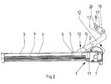
- Fig. 2
- desgleichen in Seitenansicht;
- Fig. 3
- eine Schrägansicht von hinten gesehen.
- Die Verstellmechanik besteht im Wesentlichen aus einem an Bestandteilen der Verstellmechanik befestigbaren linearen Stellantrieb 1, der einen Antriebsmotor 2 mit einer in einem Verkleidungsrohr 3 drehbar und vom Antriebsmotor 2 antreibbar gelagerten Gewindespindel 4, einer auf der Gewindespindel 4 angeordneten Spindelmutter 5, die unverdrehbar aber längsverschieblich im Verkleidungsrohr 3 geführt ist, sowie einem Gleiter 6, der mit der Spindelmutter 5 gekoppelt ist und von dieser mitgenommen wird.
- Zusätzlich ist der Gleiter 6 außen auf dem Verkleidungsrohr 3 längs desselben verschieblich geführt, was durch entsprechende Formgebung des Gleiters in Anpassung an die Form des Verkleidungsrohres 3 erreicht wird.
- Der Gleiter 6 ist über ein Hebelgetriebe 7 mit einem Stellmittel 8, vorzugsweise mit einem drehbaren Rohr der Verstellmechanik gekoppelt. Das Verkleidungsrohr 3 weist Seitenflächen auf, von denen mindestens eine, vorzugsweise beide einen Längsschlitz 9 aufweisen, der als Durchgriff für Bestandteile des Gleiters 6 zur Verbindung mit der Spindelmutter 5 dienen. Des Weiteren weist das Verkleidungsrohr eine Unterseite und eine Oberseite auf, wobei die Oberseite von dem Gleiter 6 übergriffen ist.
- An dem die Oberseite des Verkleidungsrohres 3 übergreifenden Teil des Gleiters 6 ist ein von dessen Oberseite abragender Lagerbock 10 fixiert oder ausgebildet. An diesem Lagerbock 10 ist ein erstes Ende 11 eines das Hebelgetriebe 7 bildenden Schwenkhebels 12 angelenkt. Das zweite Ende 13 des Schwenkhebels 12 ist an einer Lagerlasche 21 angelenkt, die an dem Stellmittel 8 für das Möbelteil, insbesondere dem drehbaren Rohr, der Verstellmechanik befestigt ist.
- Der Lagerbock 10 weist zwei zueinander parallel gerichtete Lagerbügel 14 mit Durchgangslochung auf. Das erste Ende 11 des Schwenkhebels 12 ist zwischen diesen Lagerbügeln 14 angeordnet und von einem die Lagerbügel 14 und eine Lochung des ersten Endes 11 durchgreifenden Kopfbolzen 15 durchsetzt, wobei der Kopf des Kopfbolzens 15 sich an einer Seitenfläche eines ersten der Lagerbügel 14 abstützt und der Schaft des Kopfbolzens 15 über den zweiten der Lagerbügel 14 nach außen vorragt und mit einem den vorragenden Bereich quer durchsetzenden Splint 16 gesichert und fixiert ist.
- Die Lagerlasche 21 ist als L-förmiges Winkelstück ausgebildet, wie insbesondere in
Figur 3 ersichtlich ist, wobei der erste Schenkel 17 des Winkelstücks von einem Niet 18 durchgriffen ist, mittels dessen das zweite Ende 13 des Schenkhebels 12 drehbar angelenkt ist. Im zweiten Schenkel 19 des Winkelstücks sind zwei Lochungen in Längsrichtung des Schenkels 19 voneinander beanstandet ausgebildet, die von Kopfschrauben 20 durchgriffen sind, die in an dem Stellmittel 8 für das Möbelteil in dessen Längsrichtung voneinander beabstandete Gewindelöcher eingeschraubt sind. - Wie insbesondere in
Figur 2 ersichtlich, ist der Schwenkhebel 12 L-förmig ausgebildet, wobei der eingeschlossene Winkel nicht exakt rechtwinklig ist, sondern leicht geöffnet ist, also leicht stumpfwinklig gebildet ist. Der längere Schenkel bildet das erste Ende 11 des Schwenkhebels 12 und der kürzere Schenkel bildet das zweite Ende 13 des Schwenkhebels 12. - Die Erfindung stellt eine Verstellmechanik zur Verfügung, die mit wenigen Schrauben vom Benutzer endmontierbar ist, die aus wenigen Einzelteilen besteht und die kostengünstig und funktionell gestaltet ist.
- Die Erfindung ist nicht auf das Ausführungsbeispiel beschränkt, sondern im Rahmen der Offenbarung vielfach variabel.
- Alle in der Beschreibung und/oder Zeichnung offenbarten Einzel- und Kombinationsmerkmale werden als erfindungswesentlich angesehen.
Claims (5)
- Verstellmechanik zur Verstellung von beweglichen Möbelteilen, bestehend aus einem an Bestandteilen der Verstellmechanik befestigbaren linearen Stellantrieb (1), der einen Antriebsmotor (2) mit einer in einem Verkleidungsrohr (3) drehbar und vom Antriebsmotor (2) antreibbar gelagerten Gewindespindel (4), einer auf der Gewindespindel (4) angeordneten Spindelmutter (5), die unverdrehbar aber längsverschieblich im Verkleidungsrohr (3) geführt ist, sowie einem Gleiter (6), der mit der Spindelmutter (5) bewegungsgekoppelt ist und außen auf dem Verkleidungsrohr (3) längs desselben verschieblich geführt ist, wobei der Gleiter (6) über ein Hebelgetriebe (7) mit einem Stellmittel (8) für ein Möbelteil, vorzugsweise mit einem drehbaren Rohr der Verstellmechanik gekoppelt ist, und wobei das Verkleidungsrohr (3) Seitenflächen aufweist, von denen mindestens eine einen Längsschlitz (9) als Durchgriff für Bestandteile des Gleiters (6) zur Verbindung mit der Spindelmutter (5) sowie eine Unterseite und eine Oberseite, wobei die Oberseite von dem Gleiter (6) übergriffen ist, dadurch gekennzeichnet, dass an dem die Oberseite des Verkleidungsrohrs (3) übergreifenden Teil des vorzugsweise im Querschnitt U-förmigen Gleiters (6) ein von der Oberseite abragender Lagerbock (10) fixiert oder ausgebildet ist, dass am Lagerbock (10) ein erstes Ende (11) eines das Hebelgetriebe bildenden Schwenkhebels (12) angelenkt ist, dass das zweite Ende (13) des Schwenkhebels (12) an einer Lagerlasche (21) angelenkt ist, die an dem Stellmittel (8) für das Möbelteil, insbesondere dem drehbaren Rohr, der Verstellmechanik befestigt ist.
- Verstellmechanik zur Verstellung von beweglichen Möbelteilen nach Anspruch 1, dadurch gekennzeichnet, dass der Lagerbock (10) zwei zueinander parallel gerichtete Lagerbügel (14) mit Durchgangslochung aufweist, das erste Ende (11) des Schwenkhebels (12) zwischen diesen angeordnet und von einem die Lagerbügel (14) und das erste Ende (11) durchgreifenden Kopfbolzen (15) durchsetzt ist, wobei der Kopf des Kopfbolzens (15) sich an einer Seitenfläche eines ersten Lagerbügels (14) abstützt, und der Schaft des Kopfbolzens (15) über den zweiten Lagerbügel (14) vorragt und mit einem den vorragenden Bereich quer durchsetzenden Splint (16) gesichert und fixiert ist.
- Verstellmechanik zur Verstellung von beweglichen Möbelteilen nach Anspruch 1 oder 2, dadurch gekennzeichnet, dass die Lagerlasche (21) als L-förmiges Winkelstück ausgebildet ist, dessen erster Schenkel (17) endseitig von einem Niet (18) durchgriffen ist, mittels dessen das zweite Ende (13) des Schwenkhebels (12) drehbar angelenkt ist.
- Verstellmechanik zur Verstellung von beweglichen Möbelteilen nach einem Anspruch 3, dadurch gekennzeichnet, dass im zweiten Schenkel (19) des Winkelstücks zwei Lochungen in Längsrichtung des Schenkels (19) voneinander beabstandet ausgebildet sind, die von Kopfschrauben (20) durchgriffen sind, die in an dem Stellmittel (8) für das Möbelteil, insbesondere an dem drehbaren Rohr, in dessen Längsrichtung voneinander beabstandete Gewindelöcher eingeschraubt sind.
- Verstellmechanik zur Verstellung von beweglichen Möbelteilen nach einem der Ansprüche 1 bis 4, dadurch gekennzeichnet, dass der Schwenkhebel (12) L-förmig ausgebildet ist, wobei der längere Schenkel das erste Ende (11) des Schwenkhebels (12) und der kürzere Schenkel das zweite Ende (13) des Schenkelhebels (12) aufweist oder bildet.
Applications Claiming Priority (2)
| Application Number | Priority Date | Filing Date | Title |
|---|---|---|---|
| DE201310106388 DE102013106388B3 (de) | 2013-06-19 | 2013-06-19 | Verstellmechanik zur Verstellung von beweglichen Möbelteilen |
| US201361862409P | 2013-08-05 | 2013-08-05 |
Publications (3)
| Publication Number | Publication Date |
|---|---|
| EP2815681A2 true EP2815681A2 (de) | 2014-12-24 |
| EP2815681A3 EP2815681A3 (de) | 2016-03-09 |
| EP2815681B1 EP2815681B1 (de) | 2020-11-11 |
Family
ID=50670602
Family Applications (1)
| Application Number | Title | Priority Date | Filing Date |
|---|---|---|---|
| EP14401072.5A Not-in-force EP2815681B1 (de) | 2013-06-19 | 2014-06-11 | Verstellmechanik zur verstellung von beweglichen möbelteilen |
Country Status (6)
| Country | Link |
|---|---|
| US (4) | US9732832B2 (de) |
| EP (1) | EP2815681B1 (de) |
| JP (1) | JP6091465B2 (de) |
| CN (1) | CN103795180B (de) |
| DE (1) | DE102013106388B3 (de) |
| WO (1) | WO2015020972A2 (de) |
Cited By (1)
| Publication number | Priority date | Publication date | Assignee | Title |
|---|---|---|---|---|
| CN107613810A (zh) * | 2015-03-20 | 2018-01-19 | L & P 产权管理公司 | 用于座椅单元的自动定位装置 |
Families Citing this family (25)
| Publication number | Priority date | Publication date | Assignee | Title |
|---|---|---|---|---|
| DE102013106388B3 (de) * | 2013-06-19 | 2014-10-09 | Limoss Gmbh & Co. Kg | Verstellmechanik zur Verstellung von beweglichen Möbelteilen |
| US20180092464A1 (en) * | 2015-03-31 | 2018-04-05 | Octo Group Ag | Adjustable padding device |
| RU2620840C2 (ru) * | 2015-10-02 | 2017-05-30 | федеральное государственное бюджетное образовательное учреждение высшего образования "Национальный исследовательский университет "МЭИ" (ФГБОУ ВО "НИУ "МЭИ") | Способ сборки подвижного стола манипулятора с двумя шаговыми двигателями |
| US10334050B2 (en) * | 2015-11-04 | 2019-06-25 | Zoox, Inc. | Software application and logic to modify configuration of an autonomous vehicle |
| CN205480073U (zh) * | 2015-12-09 | 2016-08-17 | 炼马机电(深圳)有限公司 | 一种连接用驱动块 |
| CN205319852U (zh) * | 2016-01-21 | 2016-06-15 | 炼马机电(深圳)有限公司 | 驱动器 |
| US10461605B2 (en) | 2016-01-21 | 2019-10-29 | Limoss (Shenzhen) Co., Ltd. | Actuator having a detachable slide guide fastener |
| CN108135359B (zh) * | 2016-09-18 | 2021-01-15 | 炼马机电(东莞)有限公司 | 驱动器及驱动器的安装结构 |
| US10750869B2 (en) | 2017-07-06 | 2020-08-25 | Ashley Furniture Industries, Inc. | Motion furniture mechanism with pre-aligned linkage member |
| US10349748B2 (en) | 2017-08-11 | 2019-07-16 | Ashley Furniture Industries, Inc. | Torsion activator for motion furniture |
| US11134781B2 (en) | 2017-08-14 | 2021-10-05 | Ashley Furniture Industries, Inc. | Frame structure and assembly method for motion furniture |
| CN110495079B (zh) * | 2018-05-15 | 2021-10-29 | 炼马机电(东莞)有限公司 | 一种线性驱动器 |
| CN110546869B (zh) | 2018-10-17 | 2021-05-04 | 炼马机电(东莞)有限公司 | 驱动块、线性驱动器及可调用具 |
| US11672348B2 (en) | 2018-11-05 | 2023-06-13 | La-Z-Boy Incorporated | Furniture member having lumbar adjustment mechanism |
| US10952535B2 (en) * | 2018-11-05 | 2021-03-23 | La-Z-Boy Incorporated | Furniture member having lumbar adjustment mechanism |
| US11324324B2 (en) | 2018-11-05 | 2022-05-10 | La-Z-Boy Incorporated | Furniture member having lumbar adjustment mechanism |
| CN212811478U (zh) * | 2018-11-28 | 2021-03-26 | 炼马机电(东莞)有限公司 | 直线驱动器、驱动器装置 |
| EP3708870B1 (de) | 2019-03-14 | 2021-11-17 | AIRBUS HELICOPTERS DEUTSCHLAND GmbH | Kraftübertragungssystem |
| US11168770B2 (en) * | 2019-05-23 | 2021-11-09 | Brose Fahrzeugteile Gmbh & Co. Kommanditgesellschaft, Bamberg | Vehicle drive mechanism |
| DE102019211932A1 (de) | 2019-08-08 | 2021-02-11 | Brose Fahrzeugteile Se & Co. Kommanditgesellschaft, Bamberg | Türantriebsvorrichtung mit einer eine Führungsschiene umfassenden Getriebebaugruppe |
| US20230270260A1 (en) * | 2020-08-12 | 2023-08-31 | De Werth Group Ag | Support Device Adjustable by Means of an Electric Motor |
| US20220378637A1 (en) * | 2020-09-18 | 2022-12-01 | Modern Healthcare Equipment Llc | Portable medical lift and positioning device and adapter therefore |
| US12114777B2 (en) * | 2021-12-23 | 2024-10-15 | Chuan-Hang Shih | Foldable electric bed |
| CA3250921A1 (en) * | 2022-05-09 | 2023-11-16 | La-Z-Boy Incorporated | FURNITURE ELEMENT WITH LUMBAR ADJUSTMENT MECHANISM |
| TWI803397B (zh) * | 2022-07-21 | 2023-05-21 | 施權航 | 電動床 |
Family Cites Families (55)
| Publication number | Priority date | Publication date | Assignee | Title |
|---|---|---|---|---|
| US1736878A (en) * | 1927-09-28 | 1929-11-26 | Smith & Davis Mfg Company | Bed construction |
| US3858452A (en) * | 1973-07-09 | 1975-01-07 | Vemco Products Inc | Emergency release for screw drive operator traveler assembly |
| US4061019A (en) * | 1976-03-16 | 1977-12-06 | Blasetti David H | Apparatus for generating forces in a specimen |
| US4155269A (en) * | 1977-09-16 | 1979-05-22 | Clopay Corporation | Traveler and guide rail apparatus for screw drive closure operator |
| US4494259A (en) * | 1981-11-25 | 1985-01-22 | Simmons Universal Corporation | Adjustable bed |
| US4675926A (en) * | 1983-08-17 | 1987-06-30 | Lindblom Hans Olov | Chair and/or bed arrangement |
| US4696512A (en) * | 1986-03-06 | 1987-09-29 | Berkline Corporation | Motorized recliner chair with release mechanism |
| JPH031651U (de) * | 1989-05-18 | 1991-01-09 | ||
| US4962676A (en) * | 1989-10-12 | 1990-10-16 | The Gillette Company | Two axis transfer device |
| IT1255477B (it) * | 1992-07-31 | 1995-11-06 | Egidio Marcantoni | Dispositivo per l'azionamento di reti per letti o divani con testata e/o pediera ad angolazione variabile |
| US5329657A (en) * | 1992-10-21 | 1994-07-19 | Stryker Corporation | Quick release coupling for head section of a hospital bed |
| US5537701A (en) * | 1994-03-15 | 1996-07-23 | Maxwell Products, Inc. | Adjustable articulated bed |
| US5588257A (en) * | 1994-08-24 | 1996-12-31 | The Stanley Works | Garage door operator |
| WO1996012123A1 (de) * | 1994-10-18 | 1996-04-25 | Dietmar Koch | Antrieb zur verstellung von teilen von sitz- und liegemöbeln |
| JP3702494B2 (ja) * | 1995-07-13 | 2005-10-05 | アイシン精機株式会社 | 電動機 |
| JP3117118B2 (ja) * | 1995-07-31 | 2000-12-11 | ヒーハイスト精工株式会社 | 多自由度位置決め機構 |
| JP3705641B2 (ja) * | 1996-01-19 | 2005-10-12 | Smc株式会社 | アクチュエータ |
| US5903125A (en) * | 1997-02-06 | 1999-05-11 | Speedline Technologies, Inc. | Positioning system |
| JP2000088071A (ja) * | 1998-09-18 | 2000-03-28 | Smc Corp | 電動アクチュエータ |
| US6402444B1 (en) * | 1999-04-29 | 2002-06-11 | Tsinghua University | Type of parallel machine tool frame driven by slider and extensible strut |
| US6250170B1 (en) * | 1999-09-15 | 2001-06-26 | Emerson Electric Co. | Load directing trunnion mount for linear actuator |
| DE10012781A1 (de) * | 2000-03-16 | 2001-09-27 | Boellhoff Gmbh | Verbindungsanordnung zum Anbringen eines Befestigungselementes an einem Bauteil |
| EP1161907A1 (de) * | 2000-06-09 | 2001-12-12 | Schätti AG | Vorrichtung zum Verstellen eines schwenkbaren Abschnitts an einem Sitz-oder Liegemöbel |
| AU9368201A (en) | 2000-10-03 | 2002-04-15 | Linak As | A linear actuator |
| JP2003024393A (ja) * | 2001-07-16 | 2003-01-28 | Nippon Bed Seizo Kk | 半身起床ベッド |
| US6668396B2 (en) * | 2001-12-28 | 2003-12-30 | Ching-Hua Wei | Turning mechanism for a patient confined to a bed |
| CN2563816Y (zh) * | 2002-07-10 | 2003-07-30 | 华林 | 一种带离合装置的管状电机 |
| DE20302142U1 (de) | 2002-09-16 | 2003-04-24 | Dewert Antriebs- und Systemtechnik GmbH & Co KG, 32278 Kirchlengern | Elektromotorischer Möbelantrieb |
| JP2006266310A (ja) * | 2005-03-22 | 2006-10-05 | Ntn Corp | 電動リニアアクチュエータ |
| US7237286B1 (en) * | 2006-01-20 | 2007-07-03 | Kim Willie W | Articulating bed |
| JP5133572B2 (ja) * | 2006-02-02 | 2013-01-30 | 株式会社ブリヂストン | 動的吸振装置及びインホイールモータの取付方法と取付構造 |
| DE102006027523A1 (de) * | 2006-06-14 | 2008-01-10 | Rk Rose + Krieger Gmbh Verbindungs- Und Positioniersysteme | Lineareinheit |
| DE102006033982B4 (de) * | 2006-07-22 | 2009-03-05 | Stabilus Gmbh | Spindelantrieb |
| JP2008049903A (ja) * | 2006-08-25 | 2008-03-06 | Delta Kogyo Co Ltd | 車両用パワーシートのトランスミッション構造 |
| WO2008031274A1 (en) * | 2006-09-12 | 2008-03-20 | Kuo-An Wang | Adjusting device for seating and reclining furniture |
| DE202006018505U1 (de) * | 2006-12-05 | 2008-04-17 | Dewert Antriebs- Und Systemtechnik Gmbh | Elektromotorischer Linearantrieb |
| US7533591B2 (en) | 2007-03-03 | 2009-05-19 | T-Motion Technology Co., Ltd. | Fast-releasing controlling device of actuator for electric sickbed |
| US7717005B2 (en) * | 2007-04-04 | 2010-05-18 | T-Motion Technology Co., Ltd. | Slide mechanism of linear transmission apparatus |
| DE112008001416A5 (de) * | 2007-06-28 | 2010-10-28 | Linrot Holding Ag | Elektromotorisch verstellbare Stützeinrichtung |
| US7800976B2 (en) * | 2007-06-28 | 2010-09-21 | Pgs Geophysical As | Single foil lateral force and depth control device for marine seismic sensor array |
| RU2517023C2 (ru) * | 2008-01-12 | 2014-05-27 | Линак А/С | Привод |
| US8011265B2 (en) | 2008-02-11 | 2011-09-06 | Nexteer (Beijing) Technology Co., Ltd. | Modular power actuator |
| US8365470B1 (en) * | 2008-03-07 | 2013-02-05 | Campbell Frank W | Lead screw operator |
| DE102008028335B3 (de) | 2008-06-13 | 2010-05-06 | Limoss Gmbh & Co. Kg | Linearer Stellantieb für Sitz- und/oder Liegemöbel |
| JP5102715B2 (ja) * | 2008-07-30 | 2012-12-19 | Ntn株式会社 | 電動リニアアクチュエータおよびその組立方法 |
| DE602008006552D1 (de) * | 2008-09-10 | 2011-06-09 | Man Wah Furniture Mfg Huizhou Co Ltd | Ansteuerung zum Einstellen von Sitz- und Liegemöbelteilen |
| TWI371334B (en) * | 2009-05-05 | 2012-09-01 | Univ Chung Yuan Christian | Toggle type with one axial positioning machine |
| GB0917693D0 (en) * | 2009-10-09 | 2009-11-25 | Goodrich Actuation Systems Ltd | Actuator arrangement |
| GB201006099D0 (en) * | 2010-04-13 | 2010-05-26 | Airbus Operations Ltd | Slat support assembly |
| US8823229B2 (en) | 2010-06-04 | 2014-09-02 | Aries Engineering Company, Inc. | Electro-mechanical actuator |
| WO2012083951A1 (en) | 2010-12-21 | 2012-06-28 | Linak A/S | Linear actuator |
| CN203027077U (zh) * | 2013-01-01 | 2013-06-26 | 浙江胜华波电器股份有限公司 | 电枢轴双蜗杆式刮水器电机 |
| TWI499731B (zh) * | 2013-01-17 | 2015-09-11 | Timotion Technology Co Ltd | 線性傳動裝置改良 |
| DE102013106388B3 (de) | 2013-06-19 | 2014-10-09 | Limoss Gmbh & Co. Kg | Verstellmechanik zur Verstellung von beweglichen Möbelteilen |
| CA2975418C (en) * | 2014-01-29 | 2018-10-23 | Billy Joe GRIGGS, Jr. | Motor assembly for reclining furniture |
-
2013
- 2013-06-19 DE DE201310106388 patent/DE102013106388B3/de not_active Expired - Fee Related
- 2013-12-25 CN CN201310725269.1A patent/CN103795180B/zh active Active
-
2014
- 2014-06-06 JP JP2014118059A patent/JP6091465B2/ja active Active
- 2014-06-11 EP EP14401072.5A patent/EP2815681B1/de not_active Not-in-force
- 2014-07-29 US US14/445,432 patent/US9732832B2/en not_active Expired - Fee Related
- 2014-07-29 US US14/445,399 patent/US20150033885A1/en not_active Abandoned
- 2014-08-04 WO PCT/US2014/049631 patent/WO2015020972A2/en not_active Ceased
-
2017
- 2017-06-30 US US15/639,307 patent/US10066717B2/en active Active
-
2018
- 2018-08-21 US US16/107,412 patent/US20200271205A9/en not_active Abandoned
Non-Patent Citations (1)
| Title |
|---|
| None |
Cited By (3)
| Publication number | Priority date | Publication date | Assignee | Title |
|---|---|---|---|---|
| CN107613810A (zh) * | 2015-03-20 | 2018-01-19 | L & P 产权管理公司 | 用于座椅单元的自动定位装置 |
| US10781898B2 (en) | 2015-03-20 | 2020-09-22 | L&P Property Management Company | Motorized positioning apparatus for a seating unit |
| CN107613810B (zh) * | 2015-03-20 | 2021-06-01 | L & P 产权管理公司 | 用于座椅单元的自动定位装置 |
Also Published As
| Publication number | Publication date |
|---|---|
| US10066717B2 (en) | 2018-09-04 |
| WO2015020972A2 (en) | 2015-02-12 |
| EP2815681A3 (de) | 2016-03-09 |
| US20170299027A1 (en) | 2017-10-19 |
| WO2015020972A3 (en) | 2015-04-23 |
| JP2015033321A (ja) | 2015-02-16 |
| DE102013106388B3 (de) | 2014-10-09 |
| US9732832B2 (en) | 2017-08-15 |
| CN103795180B (zh) | 2016-06-22 |
| EP2815681B1 (de) | 2020-11-11 |
| JP6091465B2 (ja) | 2017-03-08 |
| US20150033885A1 (en) | 2015-02-05 |
| CN103795180A (zh) | 2014-05-14 |
| US20180355960A1 (en) | 2018-12-13 |
| US20200271205A9 (en) | 2020-08-27 |
| US20150033538A1 (en) | 2015-02-05 |
Similar Documents
| Publication | Publication Date | Title |
|---|---|---|
| DE102013106388B3 (de) | Verstellmechanik zur Verstellung von beweglichen Möbelteilen | |
| EP2873792B1 (de) | Türband | |
| EP3988753B1 (de) | Möbelantrieb | |
| DE4106401C2 (de) | Snowboard-Bindung | |
| EP3108864B1 (de) | Faltbarer rollstuhl | |
| EP3593953A1 (de) | Tragegestell mit klapperfrei verriegelbaren tragelementen | |
| EP1726403A2 (de) | Klemmhebel mit höhenverstellbarem Gegenlager | |
| EP3150786A1 (de) | Gelenkverbindung | |
| DE102013021767B4 (de) | Spoileranordnung | |
| DE2004504C3 (de) | Längsverstelleinrichtung für Fahrzeugsitze | |
| DE102015012641B3 (de) | Gelenkverbindung | |
| CH711777B1 (de) | Türscharniervorrichtung umfassend eine Höhenverstelleinrichtung. | |
| DE202013102643U1 (de) | Verstellmechanik zur Verstellung von beweglichen Möbelteilen | |
| AT514382B1 (de) | Schließeinheit für eine Spritzgießmaschine | |
| EP2581536A2 (de) | Ecklager | |
| EP2578891B1 (de) | Adapter | |
| DE2835505C2 (de) | ||
| EP3347299B1 (de) | Führungsschiene für eine aufzugsanlage | |
| EP2385209B1 (de) | Vorrichtung zur Einstellung der Krümmung eines Türblatts | |
| EP1887151A2 (de) | Gelenkhalterung | |
| DE20100276U1 (de) | Schrittlängenverstellvorrichtung für einen Ellipsen- oder Crosstrainer | |
| EP2186445A1 (de) | Untermatratze für ein Bett | |
| DE196771C (de) | ||
| DE813515C (de) | Gelenkbeschlag | |
| AT526690A4 (de) | Scharnieranordnung für eine Tür eines Überkopfgepäckfachs |
Legal Events
| Date | Code | Title | Description |
|---|---|---|---|
| PUAI | Public reference made under article 153(3) epc to a published international application that has entered the european phase |
Free format text: ORIGINAL CODE: 0009012 |
|
| 17P | Request for examination filed |
Effective date: 20140611 |
|
| AK | Designated contracting states |
Kind code of ref document: A2 Designated state(s): AL AT BE BG CH CY CZ DE DK EE ES FI FR GB GR HR HU IE IS IT LI LT LU LV MC MK MT NL NO PL PT RO RS SE SI SK SM TR |
|
| AX | Request for extension of the european patent |
Extension state: BA ME |
|
| RIN1 | Information on inventor provided before grant (corrected) |
Inventor name: KRISTEN, MARTIN |
|
| PUAL | Search report despatched |
Free format text: ORIGINAL CODE: 0009013 |
|
| AK | Designated contracting states |
Kind code of ref document: A3 Designated state(s): AL AT BE BG CH CY CZ DE DK EE ES FI FR GB GR HR HU IE IS IT LI LT LU LV MC MK MT NL NO PL PT RO RS SE SI SK SM TR |
|
| AX | Request for extension of the european patent |
Extension state: BA ME |
|
| RIC1 | Information provided on ipc code assigned before grant |
Ipc: A47C 20/08 20060101AFI20160203BHEP Ipc: F16H 25/20 20060101ALI20160203BHEP |
|
| R17P | Request for examination filed (corrected) |
Effective date: 20160726 |
|
| RBV | Designated contracting states (corrected) |
Designated state(s): AL AT BE BG CH CY CZ DE DK EE ES FI FR GB GR HR HU IE IS IT LI LT LU LV MC MK MT NL NO PL PT RO RS SE SI SK SM TR |
|
| GRAP | Despatch of communication of intention to grant a patent |
Free format text: ORIGINAL CODE: EPIDOSNIGR1 |
|
| STAA | Information on the status of an ep patent application or granted ep patent |
Free format text: STATUS: GRANT OF PATENT IS INTENDED |
|
| INTG | Intention to grant announced |
Effective date: 20200428 |
|
| GRAS | Grant fee paid |
Free format text: ORIGINAL CODE: EPIDOSNIGR3 |
|
| GRAA | (expected) grant |
Free format text: ORIGINAL CODE: 0009210 |
|
| STAA | Information on the status of an ep patent application or granted ep patent |
Free format text: STATUS: THE PATENT HAS BEEN GRANTED |
|
| AK | Designated contracting states |
Kind code of ref document: B1 Designated state(s): AL AT BE BG CH CY CZ DE DK EE ES FI FR GB GR HR HU IE IS IT LI LT LU LV MC MK MT NL NO PL PT RO RS SE SI SK SM TR |
|
| REG | Reference to a national code |
Ref country code: GB Ref legal event code: FG4D Free format text: NOT ENGLISH |
|
| REG | Reference to a national code |
Ref country code: CH Ref legal event code: EP |
|
| REG | Reference to a national code |
Ref country code: AT Ref legal event code: REF Ref document number: 1332632 Country of ref document: AT Kind code of ref document: T Effective date: 20201115 |
|
| REG | Reference to a national code |
Ref country code: DE Ref legal event code: R096 Ref document number: 502014014982 Country of ref document: DE |
|
| REG | Reference to a national code |
Ref country code: IE Ref legal event code: FG4D Free format text: LANGUAGE OF EP DOCUMENT: GERMAN |
|
| REG | Reference to a national code |
Ref country code: NL Ref legal event code: MP Effective date: 20201111 |
|
| PG25 | Lapsed in a contracting state [announced via postgrant information from national office to epo] |
Ref country code: FI Free format text: LAPSE BECAUSE OF FAILURE TO SUBMIT A TRANSLATION OF THE DESCRIPTION OR TO PAY THE FEE WITHIN THE PRESCRIBED TIME-LIMIT Effective date: 20201111 Ref country code: RS Free format text: LAPSE BECAUSE OF FAILURE TO SUBMIT A TRANSLATION OF THE DESCRIPTION OR TO PAY THE FEE WITHIN THE PRESCRIBED TIME-LIMIT Effective date: 20201111 Ref country code: PT Free format text: LAPSE BECAUSE OF FAILURE TO SUBMIT A TRANSLATION OF THE DESCRIPTION OR TO PAY THE FEE WITHIN THE PRESCRIBED TIME-LIMIT Effective date: 20210311 Ref country code: NO Free format text: LAPSE BECAUSE OF FAILURE TO SUBMIT A TRANSLATION OF THE DESCRIPTION OR TO PAY THE FEE WITHIN THE PRESCRIBED TIME-LIMIT Effective date: 20210211 Ref country code: GR Free format text: LAPSE BECAUSE OF FAILURE TO SUBMIT A TRANSLATION OF THE DESCRIPTION OR TO PAY THE FEE WITHIN THE PRESCRIBED TIME-LIMIT Effective date: 20210212 |
|
| PG25 | Lapsed in a contracting state [announced via postgrant information from national office to epo] |
Ref country code: PL Free format text: LAPSE BECAUSE OF FAILURE TO SUBMIT A TRANSLATION OF THE DESCRIPTION OR TO PAY THE FEE WITHIN THE PRESCRIBED TIME-LIMIT Effective date: 20201111 Ref country code: LV Free format text: LAPSE BECAUSE OF FAILURE TO SUBMIT A TRANSLATION OF THE DESCRIPTION OR TO PAY THE FEE WITHIN THE PRESCRIBED TIME-LIMIT Effective date: 20201111 Ref country code: SE Free format text: LAPSE BECAUSE OF FAILURE TO SUBMIT A TRANSLATION OF THE DESCRIPTION OR TO PAY THE FEE WITHIN THE PRESCRIBED TIME-LIMIT Effective date: 20201111 Ref country code: IS Free format text: LAPSE BECAUSE OF FAILURE TO SUBMIT A TRANSLATION OF THE DESCRIPTION OR TO PAY THE FEE WITHIN THE PRESCRIBED TIME-LIMIT Effective date: 20210311 Ref country code: BG Free format text: LAPSE BECAUSE OF FAILURE TO SUBMIT A TRANSLATION OF THE DESCRIPTION OR TO PAY THE FEE WITHIN THE PRESCRIBED TIME-LIMIT Effective date: 20210211 |
|
| REG | Reference to a national code |
Ref country code: LT Ref legal event code: MG9D |
|
| PG25 | Lapsed in a contracting state [announced via postgrant information from national office to epo] |
Ref country code: HR Free format text: LAPSE BECAUSE OF FAILURE TO SUBMIT A TRANSLATION OF THE DESCRIPTION OR TO PAY THE FEE WITHIN THE PRESCRIBED TIME-LIMIT Effective date: 20201111 |
|
| PG25 | Lapsed in a contracting state [announced via postgrant information from national office to epo] |
Ref country code: SK Free format text: LAPSE BECAUSE OF FAILURE TO SUBMIT A TRANSLATION OF THE DESCRIPTION OR TO PAY THE FEE WITHIN THE PRESCRIBED TIME-LIMIT Effective date: 20201111 Ref country code: RO Free format text: LAPSE BECAUSE OF FAILURE TO SUBMIT A TRANSLATION OF THE DESCRIPTION OR TO PAY THE FEE WITHIN THE PRESCRIBED TIME-LIMIT Effective date: 20201111 Ref country code: LT Free format text: LAPSE BECAUSE OF FAILURE TO SUBMIT A TRANSLATION OF THE DESCRIPTION OR TO PAY THE FEE WITHIN THE PRESCRIBED TIME-LIMIT Effective date: 20201111 Ref country code: CZ Free format text: LAPSE BECAUSE OF FAILURE TO SUBMIT A TRANSLATION OF THE DESCRIPTION OR TO PAY THE FEE WITHIN THE PRESCRIBED TIME-LIMIT Effective date: 20201111 Ref country code: EE Free format text: LAPSE BECAUSE OF FAILURE TO SUBMIT A TRANSLATION OF THE DESCRIPTION OR TO PAY THE FEE WITHIN THE PRESCRIBED TIME-LIMIT Effective date: 20201111 Ref country code: SM Free format text: LAPSE BECAUSE OF FAILURE TO SUBMIT A TRANSLATION OF THE DESCRIPTION OR TO PAY THE FEE WITHIN THE PRESCRIBED TIME-LIMIT Effective date: 20201111 |
|
| REG | Reference to a national code |
Ref country code: DE Ref legal event code: R097 Ref document number: 502014014982 Country of ref document: DE |
|
| PG25 | Lapsed in a contracting state [announced via postgrant information from national office to epo] |
Ref country code: DK Free format text: LAPSE BECAUSE OF FAILURE TO SUBMIT A TRANSLATION OF THE DESCRIPTION OR TO PAY THE FEE WITHIN THE PRESCRIBED TIME-LIMIT Effective date: 20201111 |
|
| PLBE | No opposition filed within time limit |
Free format text: ORIGINAL CODE: 0009261 |
|
| STAA | Information on the status of an ep patent application or granted ep patent |
Free format text: STATUS: NO OPPOSITION FILED WITHIN TIME LIMIT |
|
| 26N | No opposition filed |
Effective date: 20210812 |
|
| PG25 | Lapsed in a contracting state [announced via postgrant information from national office to epo] |
Ref country code: NL Free format text: LAPSE BECAUSE OF FAILURE TO SUBMIT A TRANSLATION OF THE DESCRIPTION OR TO PAY THE FEE WITHIN THE PRESCRIBED TIME-LIMIT Effective date: 20201111 Ref country code: AL Free format text: LAPSE BECAUSE OF FAILURE TO SUBMIT A TRANSLATION OF THE DESCRIPTION OR TO PAY THE FEE WITHIN THE PRESCRIBED TIME-LIMIT Effective date: 20201111 Ref country code: IT Free format text: LAPSE BECAUSE OF FAILURE TO SUBMIT A TRANSLATION OF THE DESCRIPTION OR TO PAY THE FEE WITHIN THE PRESCRIBED TIME-LIMIT Effective date: 20201111 |
|
| PG25 | Lapsed in a contracting state [announced via postgrant information from national office to epo] |
Ref country code: ES Free format text: LAPSE BECAUSE OF FAILURE TO SUBMIT A TRANSLATION OF THE DESCRIPTION OR TO PAY THE FEE WITHIN THE PRESCRIBED TIME-LIMIT Effective date: 20201111 Ref country code: SI Free format text: LAPSE BECAUSE OF FAILURE TO SUBMIT A TRANSLATION OF THE DESCRIPTION OR TO PAY THE FEE WITHIN THE PRESCRIBED TIME-LIMIT Effective date: 20201111 |
|
| PG25 | Lapsed in a contracting state [announced via postgrant information from national office to epo] |
Ref country code: MC Free format text: LAPSE BECAUSE OF FAILURE TO SUBMIT A TRANSLATION OF THE DESCRIPTION OR TO PAY THE FEE WITHIN THE PRESCRIBED TIME-LIMIT Effective date: 20201111 |
|
| REG | Reference to a national code |
Ref country code: CH Ref legal event code: PL |
|
| GBPC | Gb: european patent ceased through non-payment of renewal fee |
Effective date: 20210611 |
|
| REG | Reference to a national code |
Ref country code: BE Ref legal event code: MM Effective date: 20210630 |
|
| PG25 | Lapsed in a contracting state [announced via postgrant information from national office to epo] |
Ref country code: LU Free format text: LAPSE BECAUSE OF NON-PAYMENT OF DUE FEES Effective date: 20210611 |
|
| PG25 | Lapsed in a contracting state [announced via postgrant information from national office to epo] |
Ref country code: LI Free format text: LAPSE BECAUSE OF NON-PAYMENT OF DUE FEES Effective date: 20210630 Ref country code: IE Free format text: LAPSE BECAUSE OF NON-PAYMENT OF DUE FEES Effective date: 20210611 Ref country code: GB Free format text: LAPSE BECAUSE OF NON-PAYMENT OF DUE FEES Effective date: 20210611 Ref country code: CH Free format text: LAPSE BECAUSE OF NON-PAYMENT OF DUE FEES Effective date: 20210630 |
|
| PG25 | Lapsed in a contracting state [announced via postgrant information from national office to epo] |
Ref country code: IS Free format text: LAPSE BECAUSE OF FAILURE TO SUBMIT A TRANSLATION OF THE DESCRIPTION OR TO PAY THE FEE WITHIN THE PRESCRIBED TIME-LIMIT Effective date: 20210311 Ref country code: FR Free format text: LAPSE BECAUSE OF NON-PAYMENT OF DUE FEES Effective date: 20210630 |
|
| PG25 | Lapsed in a contracting state [announced via postgrant information from national office to epo] |
Ref country code: BE Free format text: LAPSE BECAUSE OF NON-PAYMENT OF DUE FEES Effective date: 20210630 |
|
| REG | Reference to a national code |
Ref country code: AT Ref legal event code: MM01 Ref document number: 1332632 Country of ref document: AT Kind code of ref document: T Effective date: 20210611 |
|
| PG25 | Lapsed in a contracting state [announced via postgrant information from national office to epo] |
Ref country code: AT Free format text: LAPSE BECAUSE OF NON-PAYMENT OF DUE FEES Effective date: 20210611 |
|
| PGFP | Annual fee paid to national office [announced via postgrant information from national office to epo] |
Ref country code: DE Payment date: 20220630 Year of fee payment: 9 |
|
| PG25 | Lapsed in a contracting state [announced via postgrant information from national office to epo] |
Ref country code: HU Free format text: LAPSE BECAUSE OF FAILURE TO SUBMIT A TRANSLATION OF THE DESCRIPTION OR TO PAY THE FEE WITHIN THE PRESCRIBED TIME-LIMIT; INVALID AB INITIO Effective date: 20140611 |
|
| P01 | Opt-out of the competence of the unified patent court (upc) registered |
Effective date: 20230509 |
|
| PG25 | Lapsed in a contracting state [announced via postgrant information from national office to epo] |
Ref country code: CY Free format text: LAPSE BECAUSE OF FAILURE TO SUBMIT A TRANSLATION OF THE DESCRIPTION OR TO PAY THE FEE WITHIN THE PRESCRIBED TIME-LIMIT Effective date: 20201111 |
|
| REG | Reference to a national code |
Ref country code: DE Ref legal event code: R119 Ref document number: 502014014982 Country of ref document: DE |
|
| PG25 | Lapsed in a contracting state [announced via postgrant information from national office to epo] |
Ref country code: MK Free format text: LAPSE BECAUSE OF FAILURE TO SUBMIT A TRANSLATION OF THE DESCRIPTION OR TO PAY THE FEE WITHIN THE PRESCRIBED TIME-LIMIT Effective date: 20201111 Ref country code: DE Free format text: LAPSE BECAUSE OF NON-PAYMENT OF DUE FEES Effective date: 20240103 |
|
| PG25 | Lapsed in a contracting state [announced via postgrant information from national office to epo] |
Ref country code: TR Free format text: LAPSE BECAUSE OF FAILURE TO SUBMIT A TRANSLATION OF THE DESCRIPTION OR TO PAY THE FEE WITHIN THE PRESCRIBED TIME-LIMIT Effective date: 20201111 |
|
| PG25 | Lapsed in a contracting state [announced via postgrant information from national office to epo] |
Ref country code: MT Free format text: LAPSE BECAUSE OF FAILURE TO SUBMIT A TRANSLATION OF THE DESCRIPTION OR TO PAY THE FEE WITHIN THE PRESCRIBED TIME-LIMIT Effective date: 20201111 |