EP2816175B1 - Réception de tirant de coffrage, tirant de coffrage, ainsi qu'élément de coffrage pour la réception de celui-ci - Google Patents
Réception de tirant de coffrage, tirant de coffrage, ainsi qu'élément de coffrage pour la réception de celui-ci Download PDFInfo
- Publication number
- EP2816175B1 EP2816175B1 EP14172715.6A EP14172715A EP2816175B1 EP 2816175 B1 EP2816175 B1 EP 2816175B1 EP 14172715 A EP14172715 A EP 14172715A EP 2816175 B1 EP2816175 B1 EP 2816175B1
- Authority
- EP
- European Patent Office
- Prior art keywords
- formwork
- tie
- receptacle
- anchor
- formwork tie
- Prior art date
- Legal status (The legal status is an assumption and is not a legal conclusion. Google has not performed a legal analysis and makes no representation as to the accuracy of the status listed.)
- Active
Links
Images


Classifications
-
- E—FIXED CONSTRUCTIONS
- E04—BUILDING
- E04G—SCAFFOLDING; FORMS; SHUTTERING; BUILDING IMPLEMENTS OR AIDS, OR THEIR USE; HANDLING BUILDING MATERIALS ON THE SITE; REPAIRING, BREAKING-UP OR OTHER WORK ON EXISTING BUILDINGS
- E04G17/00—Connecting or other auxiliary members for forms, falsework structures, or shutterings
- E04G17/06—Tying means; Spacers ; Devices for extracting or inserting wall ties
- E04G17/065—Tying means, the tensional elements of which are threaded to enable their fastening or tensioning
- E04G17/0651—One-piece elements
- E04G17/0652—One-piece elements fully recoverable
-
- E—FIXED CONSTRUCTIONS
- E04—BUILDING
- E04G—SCAFFOLDING; FORMS; SHUTTERING; BUILDING IMPLEMENTS OR AIDS, OR THEIR USE; HANDLING BUILDING MATERIALS ON THE SITE; REPAIRING, BREAKING-UP OR OTHER WORK ON EXISTING BUILDINGS
- E04G11/00—Forms, shutterings, or falsework for making walls, floors, ceilings, or roofs
- E04G11/36—Forms, shutterings, or falsework for making walls, floors, ceilings, or roofs for floors, ceilings, or roofs of plane or curved surfaces end formpanels for floor shutterings
- E04G11/48—Supporting structures for shutterings or frames for floors or roofs
-
- E—FIXED CONSTRUCTIONS
- E04—BUILDING
- E04G—SCAFFOLDING; FORMS; SHUTTERING; BUILDING IMPLEMENTS OR AIDS, OR THEIR USE; HANDLING BUILDING MATERIALS ON THE SITE; REPAIRING, BREAKING-UP OR OTHER WORK ON EXISTING BUILDINGS
- E04G17/00—Connecting or other auxiliary members for forms, falsework structures, or shutterings
-
- E—FIXED CONSTRUCTIONS
- E04—BUILDING
- E04G—SCAFFOLDING; FORMS; SHUTTERING; BUILDING IMPLEMENTS OR AIDS, OR THEIR USE; HANDLING BUILDING MATERIALS ON THE SITE; REPAIRING, BREAKING-UP OR OTHER WORK ON EXISTING BUILDINGS
- E04G17/00—Connecting or other auxiliary members for forms, falsework structures, or shutterings
- E04G17/16—Members, e.g. consoles, for attachment to the wall to support girders, beams, or the like carrying forms or moulds for floors, lintels, or transoms
-
- E—FIXED CONSTRUCTIONS
- E04—BUILDING
- E04G—SCAFFOLDING; FORMS; SHUTTERING; BUILDING IMPLEMENTS OR AIDS, OR THEIR USE; HANDLING BUILDING MATERIALS ON THE SITE; REPAIRING, BREAKING-UP OR OTHER WORK ON EXISTING BUILDINGS
- E04G5/00—Component parts or accessories for scaffolds
- E04G5/16—Struts or stiffening rods, e.g. diagonal rods
-
- E—FIXED CONSTRUCTIONS
- E04—BUILDING
- E04G—SCAFFOLDING; FORMS; SHUTTERING; BUILDING IMPLEMENTS OR AIDS, OR THEIR USE; HANDLING BUILDING MATERIALS ON THE SITE; REPAIRING, BREAKING-UP OR OTHER WORK ON EXISTING BUILDINGS
- E04G7/00—Connections between parts of the scaffold
- E04G7/30—Scaffolding bars or members with non-detachably fixed coupling elements
- E04G7/32—Scaffolding bars or members with non-detachably fixed coupling elements with coupling elements using wedges
Definitions
- the present invention relates to a formwork anchor receptacle and a formwork anchor which are used in the field of construction.
- Formwork elements are set up at a certain distance from one another and are connected to one another by a formwork anchor before the gap formed in this way is filled with a backfill material.
- the formwork anchors are removed after the concrete has hardened so that the formwork elements can be detached from the wall formed in this way in the subsequent step.
- a formwork anchor is in accordance with the state of the art EP 2 060 703 A1 known, which is set up for tensile connection of formwork elements.
- This known formwork anchor consists of several sections or elements, the anchoring element being freely displaceable in the longitudinal direction with respect to the second anchoring section and being fixable with the engagement means.
- the DE 10 2010 002 108 A1 known an anchor system of a concrete wall formwork with at least one locking device for an anchor rod of the anchor system shows.
- the locking device comprises an annular sealing element and a screw nut element for screwing in the anchor rod.
- a spherical cap plate is provided, which can be fastened by means of fastening means to a rear side of the formwork element of the concrete wall formwork and has a spherical plate area with an opening in which the screw nut element is arranged with radial play.
- Another document is the DE 94 12 556 U1 known, which relates to a clamping device.
- This clamping device is characterized in that a spherical contact surface of the clamping nut is connected with a toothing to the dome-shaped counter surface of the washer.
- US 2116597 discloses a formwork anchor receptacle with all the technical features of the preamble of claim 1.
- a formwork anchor receptacle according to claim 1, by a formwork anchor according to claim 4, and by a formwork element according to claim 11. Further preferred embodiments can be found in the dependent claims.
- a formwork anchor receptacle is provided with a spherical section, which is arranged in a support component of a formwork element and a pivotability of the formwork anchor from the normal alignment with respect to the formwork element (for example by 4 °).
- the formwork anchor receptacle comprises a preferably cylindrical section with an opening for introducing an anchor rod and a ball section for support against a formwork element.
- the spherical configuration ensures that an offset between formwork elements located opposite anchor passage openings can be compensated for by ensuring a certain deviation from the normal to a formwork element.
- the formwork anchor receptacle or formwork anchor according to the invention ensures a load-bearing anchoring of the formwork elements and tightness with respect to the filling area formed between the formwork elements.
- the configuration according to the invention ensures that a formwork anchor can be operated from one side. The installation and connection of formwork elements is simplified in this way, and consequently labor costs can be reduced.
- a locking means in particular two holding pieces, is provided and can be inserted into the formwork anchor receptacle and locked there, in particular with an elastic fixing means, specifically for locking an anchor rod with the formwork anchor receptacle.
- the formwork anchor receptacle has an internal thread in at least a section of the opening.
- the formwork anchor receptacle can be releasably connected to an anchor rod via this thread.
- the locking means has grooves which engage in grooves in the anchor rod.
- a sealing element is in the opening at an end section of the spherical section added. In this way, leakage of the filling material introduced between formwork elements is avoided.
- the present invention relates to a formwork anchor with an anchor rod, a first formwork anchor receptacle and a second formwork anchor receptacle.
- the formwork anchor receptacles each have a preferably cylindrical section with an opening for introducing the anchor rod and a ball section for support against a formwork element.
- the first formwork anchor receptacle can be attached to a first end of the formwork anchor and the second formwork anchor receptacle to a second end of the formwork anchor.
- anchor rod is preferably conical, there is no need to use cladding tubes, which would otherwise be required for the formwork.
- the anchor rod has a screw-in limitation at the end to which the second formwork anchor receptacle is attached.
- the anchor rod In the region of the end to which the first formwork anchor receptacle is attached, the anchor rod preferably has openings through which a lock for locking the Anchor rod can be inserted with the first formwork anchor receptacle.
- the present invention is directed to a formwork element according to claim 12. Especially with high formwork elements, no additional worker is required on the operator side when the formwork anchor is installed. Even intermediate stages on the positioning side can be omitted. Furthermore, in addition to a general reduction in formwork anchors, anchor points can be saved, especially when the formwork is extended.
- anchor points are preferably arranged centrally on the formwork element, it is avoided that the formwork anchor could collide with the joint tape or other means for sealing the joint when using the formwork elements in the foundation area.
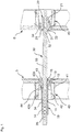
- Fig. 1 two formwork elements S are shown, between which a backfill area is formed.
- a formwork anchor is provided which has an anchor rod 30, a first formwork anchor receptacle 10 and a second formwork anchor receptacle 20.
- the first formwork anchor receptacle 10 is attached to one end of the anchor rod 30 and is supported in relation to a support component 40 attached to the formwork wall S.
- the second formwork anchor receptacle 20 is arranged at the opposite end of the anchor rod 30 and is supported on a support component 40 of the respective other formwork wall S.
- the support components 40 provided on the formwork elements S are designed such that they can accommodate elements or sections of a formwork anchor.
- the support components are preferably of essentially the same design, so that the anchor rod 30 with the first formwork anchor receptacle 10 and the second formwork anchor receptacle 20 can also be provided in a different orientation than that in FIG Figure 1 is shown.
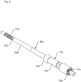
- the anchor rod 30, which is in Figure 1 extending from formwork element to formwork element, includes at a first end an external thread 31 with a screw-in limitation 32, with which, when the second formwork anchor receptacle 20 is completely screwed in, a defined position of the latter relative to the anchor rod 30 is ensured.
- the external thread 31 is followed by a conical section 33 which, in the installed state, comes into contact with the filling material, for example concrete, introduced between the formwork elements S. Since the section 33 is conical, the anchor rod 30 can be removed from the hardened filling material.
- a further external thread 34 (in particular a trapezoidal thread) which has a smaller thread pitch than the external thread 31.
- openings 35 are provided in the area of the further external thread 34, through which a lock for fixing the anchor rod 30 to the first formwork anchor receptacle 10 can be inserted.
- the second formwork anchor receptacle 20 provided in the area of the external thread 31 of the anchor rod 30 has an essentially cylindrical section 21 and a spherical section 22.
- the spherical section 22 forms a spherical curve.
- an opening 23 extends through the formwork anchor receptacle 20.
- the opening 23 of the formwork anchor receptacle 20 is provided in sections with an internal thread 24 which engages in the external thread 31 of the anchor rod 30.
- the type of screw connection described has the advantage that no impressions of the fastening means remain in the hardened backfill material, and thus an appealing concrete appearance results.
- the first formwork anchor receptacle 10 has a first end and a second end.
- a cylindrical section 11 extends between the first end and the second end and is longer compared to the cylindrical section 21 of the second formwork anchor receptacle 20, since the cylindrical section 11 of the first formwork anchor receptacle 10 also serves for the adjustability between the anchor rod 30 and the formwork anchor receptacle 10 , In this way, the formwork anchor can be adapted to different distances between the formwork elements, as will be explained in detail below.
- the first formwork anchor receptacle 10 further comprises a spherical section 12 which adjoins the cylindrical section 11 and, like the spherical section 22 of the second formwork anchor receptacle 20, forms an outer spherical curve.
- the outer shape of the spherical sections 12, 22 essentially correspond here, so that - as already mentioned - the anchor rod 30 can be connected to the formwork anchor receptacles 10, 20 in a different orientation with the formwork elements S.
- An opening 13 extends along the center axis of the cylindrical section 11 of the first formwork anchor receptacle 10.
- the anchor rod 30 in the formwork anchor receptacle 10 are inserted and come into engagement with an internal thread 14 of the formwork anchor receptacle 10.
- This internal thread 14 is provided at an end of the formwork anchor receptacle 10 opposite the ball section 12 in the region of the opening 13.
- At least one support component 40 is attached to each formwork element S.
- the number of support components 40 can vary in order to provide a secure connection between different formwork elements S. Since the support members 40 in the in Figure 1 shown embodiment on the left and right formwork element S are essentially the same, only one of the support components is provided with reference numerals.
- the support member 40 includes an attachment portion 41, which according to the present embodiment Fig. 1 is firmly connected to formwork element S.
- the support component 40 can be welded to the formwork element S.
- the support component 40 comprises a receiving and supporting section 42, which comprises a spherical ball socket 42a and a receiving area 42b.
- a receiving and supporting section 42 which comprises a spherical ball socket 42a and a receiving area 42b.
- the formwork anchor receptacle 10 is received in the area of the ball section 12 when formwork elements S are connected to the anchor rod 30.
- the design of the ball socket 42a ensures that the first formwork anchor receptacle 10 (or the second formwork anchor receptacle 20) is in contact, so that the material filled between the formwork elements S is prevented from escaping.
- the spherical ball socket 42a is provided in the area of the inner wall of the formwork element S, so that the ball section 12 (or 22) is as possible comes close to the backfill area between the formwork elements S.
- the support component 40 comprises holding means, in this embodiment a holder 44, which is detachably introduced into the receiving area 42b in order to attach the respective formwork anchor receptacle 10, 20.
- the formwork elements S are erected at a distance from one another, and the anchor rod 30 provided with the first formwork anchor receptacle 10 through one of the supporting components 40 (in Fig. 1 from left to right) introduced, the formwork anchor receptacle 20 already in the corresponding in Fig. 1 right formwork element shown is provided.
- the anchor rod 30 provided with the formwork anchor receptacle 10 is supported by the support component 40 in FIG Fig. 1 formwork element 11 shown on the left (in Figure 1 from left to right).
- the anchor rod 30 passes in sections through the support component 40 of the further formwork element S and is attached there.
- the anchor rod 30 is released by a left turn on the side of the first formwork anchor receptacle 10.
- the different thread pitches between the first formwork anchor receptacle 10 and the second formwork anchor receptacle 20 result in a relative movement between these elements during this rotation.
- the second formwork anchor receptacle 20 is detached from the anchor rod 30, and after releasing the holding means 44, the anchor rod 30 with the formwork anchor receptacle 10 attached to it is removed.
- Fig. 2 arrangement essentially corresponds to that in that of Fig. 1 ,
- differently designed support components 40a are used to receive the formwork anchor receptacles 10, 20.
- the support components 40a are cup-shaped in this case and have a radius in the area in which the respective spherical segment comes to rest.
- an anti-rotation device 50 is additionally provided for locking the anchor rod 30 on the first formwork anchor receptacle 10. This anti-rotation device 50 is applied to the anchor rod 30 after insertion of a locking element through the first formwork anchor receptacle 10 and one of the openings 35.
- the support components 40, 40a are each designed such that the formwork elements S can be stacked on top of one another. This is ensured by the fact that the section components 40, 40a have essentially no projection over the formwork element level.
- a holder 44a In the area of the first formwork anchor receptacle 10, an alternative embodiment of a holder 44a is shown, with which the formwork anchor receptacle 10 is prevented from coming out or rotating relative to the section component 40a.
- the holder 44a in this case comprises a fixing means 44a 'which protrudes beyond the level of the formwork element S. With the fixing means 44a ', the holder 44a can be attached to the support component 40a and, if necessary, removed relatively easily.
- the holder 44 provided in the area of the second formwork anchor receptacle 20 does not comprise any additional fixing means.
- brackets 44a, 44 shows that these can be used depending on the specific application and can be freely combined with the other components.
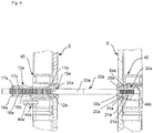
- Fig. 4 relates to an embodiment of the present invention.
- circumferential grooves or recesses 34a with a rectangular cross section or a trapezoidal cross section are provided on the anchor rod 30a in the area of the first formwork anchor receptacle 10a.
- Several of these grooves are provided with markings that allow a certain rough orientation when adjusting the length of the formwork anchor.
- An opening 16a is provided in that section of the first formwork anchor receptacle 10a opposite the ball section 12a.
- Two half-shell holding pieces 17a are inserted into this opening 16a together with the anchor rod 30a.
- the half-shell holding pieces 17a After the half-shell holding pieces 17a have grooves 17b on their inner side which engage in the grooves 34a of the anchor rod 30a, the half-shell holding pieces 17a are firmly connected to the anchor rod 30a after insertion into the opening 16a.
- the half-shell holding pieces 17a abut against a projection 16b in the opening 16a. From this projection 16b, an opening 13a with a smaller diameter than in the region of the opening 16a is provided.
- an elastic connecting means 18a (fixing spring ring) is introduced into the opening 16a at the end region of the opening 16a, so that half-shell holding pieces 17a are pressed against the projection 16b and thus locked with the first formwork anchor receptacle 10a.
- the second formwork anchor receptacle 20a is in the in Fig. 4 Embodiment shown with a substantially cylindrical portion 21a and a spherical portion 22a educated. However, a recess 21a ′ is provided in the region of the cylindrical section 21a, into which a holder 44b can penetrate. Furthermore, as in the first embodiment, the second formwork anchor receptacle 20a comprises an opening 23a with an internal thread 24a.
- the anchor rod 30a is formed in the area of the second formwork anchor receptacle 20a essentially the same as the first embodiment.
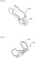
- Fig. 5a shows an embodiment of a bracket 44a (in Fig. 4 arranged on the left), which is inserted into the receiving area 42b of the support component 40 in order to fix the first or second formwork anchor receptacle in the support component.
- the holder 44a can be screwed to the formwork element S via a fixing means 44a '.
- Fig. 5b shows a further embodiment of a holder 44b (in Fig. 4 arranged on the right) for fixing a formwork anchor receptacle, preferably the second formwork anchor receptacle 20, 20a, in the support component.
- a folding spring 44b ' is used to fix the position, which is placed in the functional state on the inner wall of the ball socket. In this way, the recesses and lugs are brought into the corresponding counter-deformations in the ball socket in the functional position as a restraint and anti-rotation device.
- the integrated locking system with brackets 44, 44a, 44b offers variable connection options.
Landscapes
- Engineering & Computer Science (AREA)
- Architecture (AREA)
- Mechanical Engineering (AREA)
- Civil Engineering (AREA)
- Structural Engineering (AREA)
- Forms Removed On Construction Sites Or Auxiliary Members Thereof (AREA)
- Joining Of Building Structures In Genera (AREA)
Claims (12)
- Logement d'ancrage de coffrage (10, 10a ; 20, 20a) servant à loger une tige d'ancrage (30, 30a), laquelle tige d'ancrage (30, 30a) est prévue pour relier des éléments de coffrage (S), avec :une section (11, 11a; 21, 21a) sensiblement de forme cylindrique avec une ouverture (13, 13a ; 23, 23a) servant à introduire une tige d'ancrage (30, 30a), dans lequel la section sensiblement de forme cylindrique s'étend entre une première extrémité et une seconde extrémité du logement d'ancrage de coffrage, dans lequel le logement d'ancrage de coffrage (10, 10a ; 20, 20a) présente une section sphérique (12, 12a ; 22, 22a) située dans le prolongement de la section sensiblement de forme cylindrique, servant au soutien à l'encontre d'un élément de coffrage (S),dans lequel le logement d'ancrage de coffrage comprend un moyen de verrouillage, lequel moyen de verrouillage (17a) peut être introduit dans le logement d'ancrage de coffrage (10a) et y être verrouillé, et ce pour verrouiller une tige d'ancrage (30a) avec le logement d'ancrage de coffrage (10a),caractérisé en ce quele moyen de verrouillage (17a) présente des rainures (17b), qui peuvent venir en prise avec des rainures (34a) de la tige d'ancrage (30a).
- Logement d'ancrage de coffrage (10a) selon la revendication 1, où le moyen de verrouillage (17a) comprend deux pièces de maintien (17a), dans lequel le moyen de verrouillage peut être fixé avec un moyen de fixation (18a) élastique servant à verrouiller une tige d'ancrage (30a) avec le logement d'ancrage de coffrage (10a) dans le logement d'ancrage de coffrage.
- Logement d'ancrage de coffrage (10, 10a) selon l'une quelconque des revendications 1 et 2, où un élément d'étanchéité (15, 15a) est logé dans l'ouverture (13, 13a) au niveau d'une section d'extrémité de la section sphérique (12, 12a).
- Ancrage de coffrage avec une tige d'ancrage (30, 30a) et un premier logement d'ancrage de coffrage (10, 10a) ainsi qu'un deuxième logement d'ancrage de coffrage (20, 20a),
dans lequel les logements d'ancrage de coffrage présentent respectivement une section (11; 21) sensiblement de forme cylindrique avec une ouverture (13, 13a ; 23, 23a) servant à introduire la tige d'ancrage (30, 30a) ainsi qu'une section sphérique (12, 12a ; 22, 22a) servant au soutien à l'encontre d'un élément de coffrage (S),
et le premier logement d'ancrage de coffrage (10, 10a) peut être installé au niveau d'une première extrémité de l'ancrage de coffrage (30, 30a) et le deuxième logement d'ancrage de coffrage (20) peut être installé au niveau d'une seconde extrémité de l'ancrage de coffrage (30, 30a),
le premier logement d'ancrage de coffrage comprend un moyen de verrouillage, lequel moyen de verrouillage (17a) peut être introduit dans le logement d'ancrage de coffrage (10a) et y être verrouillé, et ce pour verrouiller une tige d'ancrage (30a) avec le logement d'ancrage de coffrage (10a), dans lequel le moyen de verrouillage (17a) présente des rainures (17b), qui viennent en prise avec des rainures (34a) de la tige d'ancrage (30a). - Ancrage de coffrage selon la revendication 4, où le deuxième logement d'ancrage de coffrage (20, 20a) présente dans au moins une section de l'ouverture (21, 21a) un filetage intérieur (24, 24a), qui présente de manière préférée un pas autre que le filetage intérieur (14, 14a) du premier logement d'ancrage de coffrage (10, 10a) .
- Ancrage de coffrage selon la revendication 4, où le moyen de verrouillage (17a) comprend deux pièces de maintien (17a), dans lequel le moyen de verrouillage peut être fixé avec un moyen de fixation (18a) élastique servant à verrouiller une tige d'ancrage (30a) avec le logement d'ancrage de coffrage (10a) dans le logement d'ancrage de coffrage.
- Ancrage de coffrage selon la revendication 6, où le moyen de verrouillage (17a) présente des rainures (17b), qui viennent en prise avec des rainures (34a) de la tige d'ancrage (30a).
- Ancrage de coffrage selon l'une quelconque des revendications 4 à 7, où un élément d'étanchéité (15, 15a) est logé dans l'ouverture (13, 13a) au niveau d'une section d'extrémité de la section sphérique (12, 12a) du premier logement d'ancrage de coffrage (10, 10a) .
- Ancrage de coffrage selon l'une quelconque des revendications 4 à 8, où la tige d'ancrage (30, 30a) présente, au niveau de l'extrémité au niveau de laquelle le deuxième logement d'ancrage de coffrage (20, 20a) est installé, une délimitation de vissage (32, 32a) .
- Ancrage de coffrage selon l'une quelconque des revendications 4 à 9, où la tige d'ancrage (30, 30a) présente, dans la zone de l'extrémité au niveau de laquelle le premier logement d'ancrage de coffrage (10, 10a) est installé, des ouvertures (35), à travers lesquelles un verrouillage servant à verrouiller la tige d'ancrage (30, 30a) avec le premier logement d'ancrage de coffrage (10, 10a) peut être introduit.
- Elément de coffrage (S) avec un logement d'ancrage de coffrage (10, 10a ; 20, 20a) selon l'une quelconque des revendications 1 à 3 ou d'un ancrage de coffrage selon l'une quelconque des revendications 4 à 10 ainsi qu'avec un composant de soutien (40, 40a) servant à loger le logement d'ancrage de coffrage (10, 10a ; 20, 20a) selon l'une quelconque des revendications 1 à 3 ou de l'ancrage de coffrage selon l'une quelconque des revendications 4 à 10, dans lequel le composant de soutien (40, 40a) présente un coussinet sphérique (42a) servant à loger la section sphérique (12, 12a), dans lequel le coussinet sphérique (42a) est disposé de manière préférée au niveau du côté, tourné vers une zone de remplissage, de l'élément de coffrage (S) .
- Elément de coffrage (S) selon la revendication 11, où un moyen de maintien (44, 44a, 44b) servant à installer le logement d'ancrage de coffrage (10, 10a ; 20, 20a) respectif peut être introduit dans le composant de soutien.
Applications Claiming Priority (1)
| Application Number | Priority Date | Filing Date | Title |
|---|---|---|---|
| DE102013211490.7A DE102013211490A1 (de) | 2013-06-19 | 2013-06-19 | Schalungsankeraufnahme, Schalungsanker sowie Schalungselement zur Aufnahme dieser |
Publications (2)
| Publication Number | Publication Date |
|---|---|
| EP2816175A1 EP2816175A1 (fr) | 2014-12-24 |
| EP2816175B1 true EP2816175B1 (fr) | 2020-01-15 |
Family
ID=50943186
Family Applications (1)
| Application Number | Title | Priority Date | Filing Date |
|---|---|---|---|
| EP14172715.6A Active EP2816175B1 (fr) | 2013-06-19 | 2014-06-17 | Réception de tirant de coffrage, tirant de coffrage, ainsi qu'élément de coffrage pour la réception de celui-ci |
Country Status (5)
| Country | Link |
|---|---|
| US (2) | US9222271B2 (fr) |
| EP (1) | EP2816175B1 (fr) |
| CA (2) | CA3013533C (fr) |
| DE (1) | DE102013211490A1 (fr) |
| ES (1) | ES2782598T3 (fr) |
Families Citing this family (26)
| Publication number | Priority date | Publication date | Assignee | Title |
|---|---|---|---|---|
| DE102014211483A1 (de) * | 2014-06-16 | 2015-12-17 | Peri Gmbh | Ankerkonusvorrichtung, Schalungsanker und Betonschalungssystem |
| DE102014012037A1 (de) * | 2014-08-16 | 2016-02-18 | Redima Ag | Ankervorrichtung einer Betonwandschalung, Schalungselement und Verfahren zum Montieren einer Ankervorrichtung |
| EP3156561A1 (fr) * | 2015-07-03 | 2017-04-19 | MEVA Schalungs-Systeme GmbH | Élément de coffrage |
| FR3045689B1 (fr) * | 2015-12-16 | 2017-12-15 | Hussor | Dispositif de maintien et de relachement de tension axiale d'une tige |
| EP3181781A1 (fr) | 2015-12-18 | 2017-06-21 | DOKA GmbH | Receptacle de tirant de coffrage |
| EP3258033A1 (fr) * | 2016-06-17 | 2017-12-20 | ULMA C y E, S. COOP. | Dispositif d'ancrage destiné à un coffrage vertical et ledit coffrage |
| EP3258032A1 (fr) | 2016-06-17 | 2017-12-20 | ULMA C y E, S. Coop | Dispositif d'ancrage destiné à un coffrage vertical et ledit coffrage |
| AT519099B1 (de) * | 2016-11-16 | 2018-04-15 | Ringer Kg | Vorrichtung zur lösbaren Abstützung eines Schalungsanker an einem Schalungselement einer Betonwandschalung |
| AT519100B1 (de) * | 2016-11-16 | 2018-04-15 | Ringer Kg | Vorrichtung zur Aufnahme eines Schalungsankers in einem Schalungselement einer Betonwandschalung |
| ES2726030T3 (es) * | 2017-04-06 | 2019-10-01 | Ulma C Y E S Coop | Encofrado vertical con un anclaje roscado |
| EP3385469B1 (fr) | 2017-04-06 | 2019-12-18 | ULMA C y E, S. COOP. | Ensemble d'ancrage pour un coffrage vertical et coffrage vertical |
| ES2856973T3 (es) * | 2017-04-06 | 2021-09-28 | Ulma C Y E S Coop | Anclaje para un encofrado vertical y encofrado vertical que comprende uno de dichos anclajes. |
| EP3399120B1 (fr) * | 2017-05-04 | 2023-02-01 | MEVA Schalungs-Systeme GmbH | Système de coffrage à ancre comprenant deux éléments de coffrage éloignés l'un de l'autre, son procédé de montage |
| CA3006922A1 (fr) * | 2018-06-01 | 2019-12-01 | At-Pac China Business Trust | Longeron d'echafaudage |
| PL3587705T3 (pl) * | 2018-06-22 | 2022-01-31 | Ulma C Y E, S. Coop. | Szalunek pionowy |
| ES2757985B2 (es) * | 2018-10-30 | 2021-04-13 | Inveral S L | Conector para sistemas de encofrado y sistema de encofrado asociado al mismo |
| EP3653810B1 (fr) * | 2018-11-15 | 2024-05-08 | DOKA GmbH | Panneau de coffrage, système de coffrage et procédé de montage d'un tirant |
| DE102019109066B4 (de) * | 2019-04-05 | 2021-02-18 | Paschal-Werk G. Maier Gmbh | Ankervorrichtung |
| IT201900010785A1 (it) | 2019-07-03 | 2021-01-03 | Betonfer S N C Di Pangerc Aleksandra & Co | Sistema di armatura dei muri in cemento armato facilmente eseguibile da un solo lato. |
| CN110847604B (zh) * | 2019-11-29 | 2021-03-09 | 宁波市鄞州金本机械有限公司 | 一种建筑模板紧固套件 |
| DE102020101188A1 (de) * | 2020-01-20 | 2021-07-22 | Peri Gmbh | Rahmenschalungselement |
| EP3951116B1 (fr) * | 2020-08-04 | 2024-01-31 | MEVA Schalungs-Systeme GmbH | Tirant de coffrage |
| EP4381151A2 (fr) * | 2021-08-03 | 2024-06-12 | Peri Se | Système de poutre de grille pour coffrage de dalle |
| CN113882287A (zh) * | 2021-08-24 | 2022-01-04 | 上海宝冶集团有限公司 | 一种涵洞涵身模板支模系统及其施工方法 |
| CN114232984A (zh) * | 2021-12-28 | 2022-03-25 | 晟通科技集团有限公司 | 模板及模板体系 |
| CN115573339B (zh) * | 2022-11-24 | 2025-11-25 | 中交建筑集团有限公司 | 一种可回收式排水土钉装置及施工方法 |
Family Cites Families (13)
| Publication number | Priority date | Publication date | Assignee | Title |
|---|---|---|---|---|
| US2116597A (en) | 1935-10-25 | 1938-05-10 | Samuel S Colt | Concrete form tie |
| US2172461A (en) | 1936-08-24 | 1939-09-12 | Anthony C Fischer | Form clamp |
| DE9412556U1 (de) | 1994-08-04 | 1994-10-06 | Döllen, Heinz von, 58239 Schwerte | Spanneinrichtung |
| US6935607B2 (en) | 2002-10-23 | 2005-08-30 | Western Forms, Inc. | Forming panel with extruded elongated threaded slot for receiving threaded attachment members |
| DE102006023062A1 (de) * | 2006-05-10 | 2007-11-15 | Robusta-Gaukel Gmbh & Co. Kg | Spannvorrichtung für Ankerstäbe von Betonschalungen |
| US20080173788A1 (en) * | 2007-01-18 | 2008-07-24 | Western Forms, Inc. | Lightweight Crane-Set Forming Panel |
| DE102007004226B3 (de) * | 2007-01-27 | 2008-09-04 | Peri Gmbh | Ankersystem einer Betonwandschalung |
| US8011637B2 (en) * | 2007-06-15 | 2011-09-06 | Precise Forms, Inc. | Concrete form system for low-clearance applications |
| DE202007015833U1 (de) | 2007-11-13 | 2009-03-26 | Doka Industrie Gmbh | Schalungsanker |
| DE102010002128A1 (de) | 2010-02-18 | 2011-08-18 | MAG Europe GmbH, 73033 | Bearbeitungsanlage für Werkstücke |
| DE102010002108A1 (de) * | 2010-02-18 | 2011-08-18 | Peri GmbH, 89264 | Ankersystem einer Betonwandschalung |
| DE102010003017A1 (de) * | 2010-03-18 | 2011-09-22 | Peri Gmbh | Ankermutter und Verfahren zum Ankersetzen und Ankerlösen |
| DE102012203678A1 (de) * | 2012-03-08 | 2013-09-12 | Peri Gmbh | Ankerstabbefestigungsvorrichtung, Schalungsanker sowie Betonwandschalung |
-
2013
- 2013-06-19 DE DE102013211490.7A patent/DE102013211490A1/de not_active Withdrawn
-
2014
- 2014-06-13 CA CA3013533A patent/CA3013533C/fr active Active
- 2014-06-13 CA CA2854173A patent/CA2854173C/fr active Active
- 2014-06-17 ES ES14172715T patent/ES2782598T3/es active Active
- 2014-06-17 EP EP14172715.6A patent/EP2816175B1/fr active Active
- 2014-06-17 US US14/306,365 patent/US9222271B2/en active Active
-
2015
- 2015-11-20 US US14/947,496 patent/US9803383B2/en active Active
Non-Patent Citations (1)
| Title |
|---|
| None * |
Also Published As
| Publication number | Publication date |
|---|---|
| DE102013211490A1 (de) | 2014-12-24 |
| CA2854173A1 (fr) | 2014-12-19 |
| CA3013533C (fr) | 2020-05-05 |
| US9803383B2 (en) | 2017-10-31 |
| US9222271B2 (en) | 2015-12-29 |
| EP2816175A1 (fr) | 2014-12-24 |
| CA2854173C (fr) | 2018-11-27 |
| ES2782598T3 (es) | 2020-09-15 |
| CA3013533A1 (fr) | 2014-12-19 |
| US20140374568A1 (en) | 2014-12-25 |
| US20160097207A1 (en) | 2016-04-07 |
Similar Documents
| Publication | Publication Date | Title |
|---|---|---|
| EP2816175B1 (fr) | Réception de tirant de coffrage, tirant de coffrage, ainsi qu'élément de coffrage pour la réception de celui-ci | |
| EP2126248B1 (fr) | Système d'ancrage pour coffrage de paroi en béton | |
| EP2110565B1 (fr) | Composant de raccordement destiné à la fixation d'un élément de construction sur un élément de support | |
| EP2855947B1 (fr) | Dispositif de centrage | |
| DE69105034T2 (de) | Stahlrohrstütze für Bauschalungen. | |
| WO2011101240A1 (fr) | Système d'ancrage d'un coffrage pour mur en béton | |
| EP0002654A1 (fr) | Dispositif de fixation avec une cheville verrouillée par clavetage dans une partie d'un trou présentant un plus grand diamètre | |
| EP3586018B1 (fr) | Dispositif de fixation et module de fixation | |
| DE102012212603A1 (de) | Arretiervorrichtung mit Wandschalungsbefestigungseinrichtung und Verfahren | |
| DE3229470C2 (de) | Tunnelauskleidungssegment mit Verriegelungselementen | |
| EP3390745B1 (fr) | Receptacle de tirant de coffrage | |
| EP2060703B1 (fr) | Tirant de coffrage | |
| DE9013681U1 (de) | Vorrichtung zur Befestigung eines insbesondere rohrförmigen Bauteils an einer Wand o.dgl. | |
| EP0625622A1 (fr) | Etai télescopique | |
| EP2527549B1 (fr) | Ancrage pour charges lourdes et procédé de mise en place d'ancrages pour charges lourdes | |
| EP0848168B1 (fr) | Elément de support à réglage axial | |
| EP1353779B1 (fr) | Dispositif permettant de visser des elements de fixation | |
| EP2987924B1 (fr) | Porte-butée pour coffrage mural | |
| EP2767659B1 (fr) | Guide à barres rondes réglable en hauteur | |
| EP2471686A1 (fr) | Tendeur à cliquet | |
| EP0882898A1 (fr) | Dispositif d'ancrage | |
| EP2196599A2 (fr) | Corps de butée pour coffrages de béton | |
| EP3120072B1 (fr) | Système de fixation de mât | |
| EP3775434B1 (fr) | Bras avec une fixation par vis interne pour un support de conduit | |
| EP2362107B1 (fr) | Rivet de serrage |
Legal Events
| Date | Code | Title | Description |
|---|---|---|---|
| PUAI | Public reference made under article 153(3) epc to a published international application that has entered the european phase |
Free format text: ORIGINAL CODE: 0009012 |
|
| 17P | Request for examination filed |
Effective date: 20140617 |
|
| AK | Designated contracting states |
Kind code of ref document: A1 Designated state(s): AL AT BE BG CH CY CZ DE DK EE ES FI FR GB GR HR HU IE IS IT LI LT LU LV MC MK MT NL NO PL PT RO RS SE SI SK SM TR |
|
| AX | Request for extension of the european patent |
Extension state: BA ME |
|
| R17P | Request for examination filed (corrected) |
Effective date: 20150623 |
|
| RBV | Designated contracting states (corrected) |
Designated state(s): AL AT BE BG CH CY CZ DE DK EE ES FI FR GB GR HR HU IE IS IT LI LT LU LV MC MK MT NL NO PL PT RO RS SE SI SK SM TR |
|
| STAA | Information on the status of an ep patent application or granted ep patent |
Free format text: STATUS: EXAMINATION IS IN PROGRESS |
|
| 17Q | First examination report despatched |
Effective date: 20190116 |
|
| GRAP | Despatch of communication of intention to grant a patent |
Free format text: ORIGINAL CODE: EPIDOSNIGR1 |
|
| STAA | Information on the status of an ep patent application or granted ep patent |
Free format text: STATUS: GRANT OF PATENT IS INTENDED |
|
| RIC1 | Information provided on ipc code assigned before grant |
Ipc: E04G 17/065 20060101AFI20190910BHEP Ipc: E04G 5/16 20060101ALI20190910BHEP Ipc: E04G 7/32 20060101ALI20190910BHEP Ipc: E04G 11/48 20060101ALI20190910BHEP Ipc: E04G 17/16 20060101ALI20190910BHEP |
|
| INTG | Intention to grant announced |
Effective date: 20190930 |
|
| GRAS | Grant fee paid |
Free format text: ORIGINAL CODE: EPIDOSNIGR3 |
|
| GRAJ | Information related to disapproval of communication of intention to grant by the applicant or resumption of examination proceedings by the epo deleted |
Free format text: ORIGINAL CODE: EPIDOSDIGR1 |
|
| GRAL | Information related to payment of fee for publishing/printing deleted |
Free format text: ORIGINAL CODE: EPIDOSDIGR3 |
|
| STAA | Information on the status of an ep patent application or granted ep patent |
Free format text: STATUS: EXAMINATION IS IN PROGRESS |
|
| GRAR | Information related to intention to grant a patent recorded |
Free format text: ORIGINAL CODE: EPIDOSNIGR71 |
|
| STAA | Information on the status of an ep patent application or granted ep patent |
Free format text: STATUS: GRANT OF PATENT IS INTENDED |
|
| GRAA | (expected) grant |
Free format text: ORIGINAL CODE: 0009210 |
|
| STAA | Information on the status of an ep patent application or granted ep patent |
Free format text: STATUS: THE PATENT HAS BEEN GRANTED |
|
| INTC | Intention to grant announced (deleted) | ||
| AK | Designated contracting states |
Kind code of ref document: B1 Designated state(s): AL AT BE BG CH CY CZ DE DK EE ES FI FR GB GR HR HU IE IS IT LI LT LU LV MC MK MT NL NO PL PT RO RS SE SI SK SM TR |
|
| INTG | Intention to grant announced |
Effective date: 20191211 |
|
| REG | Reference to a national code |
Ref country code: CH Ref legal event code: EP Ref country code: GB Ref legal event code: FG4D Free format text: NOT ENGLISH |
|
| REG | Reference to a national code |
Ref country code: IE Ref legal event code: FG4D Free format text: LANGUAGE OF EP DOCUMENT: GERMAN |
|
| REG | Reference to a national code |
Ref country code: DE Ref legal event code: R096 Ref document number: 502014013459 Country of ref document: DE |
|
| REG | Reference to a national code |
Ref country code: AT Ref legal event code: REF Ref document number: 1225283 Country of ref document: AT Kind code of ref document: T Effective date: 20200215 |
|
| REG | Reference to a national code |
Ref country code: FI Ref legal event code: FGE |
|
| REG | Reference to a national code |
Ref country code: SE Ref legal event code: TRGR |
|
| REG | Reference to a national code |
Ref country code: NL Ref legal event code: MP Effective date: 20200115 |
|
| REG | Reference to a national code |
Ref country code: NO Ref legal event code: T2 Effective date: 20200115 |
|
| REG | Reference to a national code |
Ref country code: LT Ref legal event code: MG4D |
|
| PG25 | Lapsed in a contracting state [announced via postgrant information from national office to epo] |
Ref country code: NL Free format text: LAPSE BECAUSE OF FAILURE TO SUBMIT A TRANSLATION OF THE DESCRIPTION OR TO PAY THE FEE WITHIN THE PRESCRIBED TIME-LIMIT Effective date: 20200115 Ref country code: RS Free format text: LAPSE BECAUSE OF FAILURE TO SUBMIT A TRANSLATION OF THE DESCRIPTION OR TO PAY THE FEE WITHIN THE PRESCRIBED TIME-LIMIT Effective date: 20200115 Ref country code: PT Free format text: LAPSE BECAUSE OF FAILURE TO SUBMIT A TRANSLATION OF THE DESCRIPTION OR TO PAY THE FEE WITHIN THE PRESCRIBED TIME-LIMIT Effective date: 20200607 |
|
| PG25 | Lapsed in a contracting state [announced via postgrant information from national office to epo] |
Ref country code: LV Free format text: LAPSE BECAUSE OF FAILURE TO SUBMIT A TRANSLATION OF THE DESCRIPTION OR TO PAY THE FEE WITHIN THE PRESCRIBED TIME-LIMIT Effective date: 20200115 Ref country code: HR Free format text: LAPSE BECAUSE OF FAILURE TO SUBMIT A TRANSLATION OF THE DESCRIPTION OR TO PAY THE FEE WITHIN THE PRESCRIBED TIME-LIMIT Effective date: 20200115 Ref country code: GR Free format text: LAPSE BECAUSE OF FAILURE TO SUBMIT A TRANSLATION OF THE DESCRIPTION OR TO PAY THE FEE WITHIN THE PRESCRIBED TIME-LIMIT Effective date: 20200416 Ref country code: BG Free format text: LAPSE BECAUSE OF FAILURE TO SUBMIT A TRANSLATION OF THE DESCRIPTION OR TO PAY THE FEE WITHIN THE PRESCRIBED TIME-LIMIT Effective date: 20200415 Ref country code: IS Free format text: LAPSE BECAUSE OF FAILURE TO SUBMIT A TRANSLATION OF THE DESCRIPTION OR TO PAY THE FEE WITHIN THE PRESCRIBED TIME-LIMIT Effective date: 20200515 |
|
| REG | Reference to a national code |
Ref country code: ES Ref legal event code: FG2A Ref document number: 2782598 Country of ref document: ES Kind code of ref document: T3 Effective date: 20200915 |
|
| REG | Reference to a national code |
Ref country code: DE Ref legal event code: R097 Ref document number: 502014013459 Country of ref document: DE |
|
| PG25 | Lapsed in a contracting state [announced via postgrant information from national office to epo] |
Ref country code: SK Free format text: LAPSE BECAUSE OF FAILURE TO SUBMIT A TRANSLATION OF THE DESCRIPTION OR TO PAY THE FEE WITHIN THE PRESCRIBED TIME-LIMIT Effective date: 20200115 Ref country code: RO Free format text: LAPSE BECAUSE OF FAILURE TO SUBMIT A TRANSLATION OF THE DESCRIPTION OR TO PAY THE FEE WITHIN THE PRESCRIBED TIME-LIMIT Effective date: 20200115 Ref country code: SM Free format text: LAPSE BECAUSE OF FAILURE TO SUBMIT A TRANSLATION OF THE DESCRIPTION OR TO PAY THE FEE WITHIN THE PRESCRIBED TIME-LIMIT Effective date: 20200115 Ref country code: EE Free format text: LAPSE BECAUSE OF FAILURE TO SUBMIT A TRANSLATION OF THE DESCRIPTION OR TO PAY THE FEE WITHIN THE PRESCRIBED TIME-LIMIT Effective date: 20200115 Ref country code: CZ Free format text: LAPSE BECAUSE OF FAILURE TO SUBMIT A TRANSLATION OF THE DESCRIPTION OR TO PAY THE FEE WITHIN THE PRESCRIBED TIME-LIMIT Effective date: 20200115 Ref country code: LT Free format text: LAPSE BECAUSE OF FAILURE TO SUBMIT A TRANSLATION OF THE DESCRIPTION OR TO PAY THE FEE WITHIN THE PRESCRIBED TIME-LIMIT Effective date: 20200115 Ref country code: DK Free format text: LAPSE BECAUSE OF FAILURE TO SUBMIT A TRANSLATION OF THE DESCRIPTION OR TO PAY THE FEE WITHIN THE PRESCRIBED TIME-LIMIT Effective date: 20200115 |
|
| PLBE | No opposition filed within time limit |
Free format text: ORIGINAL CODE: 0009261 |
|
| STAA | Information on the status of an ep patent application or granted ep patent |
Free format text: STATUS: NO OPPOSITION FILED WITHIN TIME LIMIT |
|
| 26N | No opposition filed |
Effective date: 20201016 |
|
| PG25 | Lapsed in a contracting state [announced via postgrant information from national office to epo] |
Ref country code: MC Free format text: LAPSE BECAUSE OF FAILURE TO SUBMIT A TRANSLATION OF THE DESCRIPTION OR TO PAY THE FEE WITHIN THE PRESCRIBED TIME-LIMIT Effective date: 20200115 |
|
| PG25 | Lapsed in a contracting state [announced via postgrant information from national office to epo] |
Ref country code: SI Free format text: LAPSE BECAUSE OF FAILURE TO SUBMIT A TRANSLATION OF THE DESCRIPTION OR TO PAY THE FEE WITHIN THE PRESCRIBED TIME-LIMIT Effective date: 20200115 Ref country code: PL Free format text: LAPSE BECAUSE OF FAILURE TO SUBMIT A TRANSLATION OF THE DESCRIPTION OR TO PAY THE FEE WITHIN THE PRESCRIBED TIME-LIMIT Effective date: 20200115 |
|
| REG | Reference to a national code |
Ref country code: DE Ref legal event code: R082 Ref document number: 502014013459 Country of ref document: DE Representative=s name: WALLINGER RICKER SCHLOTTER TOSTMANN PATENT- UN, DE Ref country code: DE Ref legal event code: R082 Ref document number: 502014013459 Country of ref document: DE Representative=s name: PAUSTIAN & PARTNER PATENTANWAELTE MBB, DE |
|
| PG25 | Lapsed in a contracting state [announced via postgrant information from national office to epo] |
Ref country code: IE Free format text: LAPSE BECAUSE OF NON-PAYMENT OF DUE FEES Effective date: 20200617 |
|
| REG | Reference to a national code |
Ref country code: DE Ref legal event code: R082 Ref document number: 502014013459 Country of ref document: DE Representative=s name: WALLINGER RICKER SCHLOTTER TOSTMANN PATENT- UN, DE |
|
| PG25 | Lapsed in a contracting state [announced via postgrant information from national office to epo] |
Ref country code: TR Free format text: LAPSE BECAUSE OF FAILURE TO SUBMIT A TRANSLATION OF THE DESCRIPTION OR TO PAY THE FEE WITHIN THE PRESCRIBED TIME-LIMIT Effective date: 20200115 Ref country code: MT Free format text: LAPSE BECAUSE OF FAILURE TO SUBMIT A TRANSLATION OF THE DESCRIPTION OR TO PAY THE FEE WITHIN THE PRESCRIBED TIME-LIMIT Effective date: 20200115 Ref country code: CY Free format text: LAPSE BECAUSE OF FAILURE TO SUBMIT A TRANSLATION OF THE DESCRIPTION OR TO PAY THE FEE WITHIN THE PRESCRIBED TIME-LIMIT Effective date: 20200115 |
|
| PG25 | Lapsed in a contracting state [announced via postgrant information from national office to epo] |
Ref country code: MK Free format text: LAPSE BECAUSE OF FAILURE TO SUBMIT A TRANSLATION OF THE DESCRIPTION OR TO PAY THE FEE WITHIN THE PRESCRIBED TIME-LIMIT Effective date: 20200115 Ref country code: AL Free format text: LAPSE BECAUSE OF FAILURE TO SUBMIT A TRANSLATION OF THE DESCRIPTION OR TO PAY THE FEE WITHIN THE PRESCRIBED TIME-LIMIT Effective date: 20200115 |
|
| P01 | Opt-out of the competence of the unified patent court (upc) registered |
Effective date: 20230517 |
|
| PGFP | Annual fee paid to national office [announced via postgrant information from national office to epo] |
Ref country code: FI Payment date: 20250623 Year of fee payment: 12 |
|
| PGFP | Annual fee paid to national office [announced via postgrant information from national office to epo] |
Ref country code: DE Payment date: 20250623 Year of fee payment: 12 |
|
| PGFP | Annual fee paid to national office [announced via postgrant information from national office to epo] |
Ref country code: GB Payment date: 20250627 Year of fee payment: 12 |
|
| PGFP | Annual fee paid to national office [announced via postgrant information from national office to epo] |
Ref country code: LU Payment date: 20250625 Year of fee payment: 12 |
|
| PGFP | Annual fee paid to national office [announced via postgrant information from national office to epo] |
Ref country code: FR Payment date: 20250627 Year of fee payment: 12 |
|
| PGFP | Annual fee paid to national office [announced via postgrant information from national office to epo] |
Ref country code: AT Payment date: 20250623 Year of fee payment: 12 |
|
| PGFP | Annual fee paid to national office [announced via postgrant information from national office to epo] |
Ref country code: SE Payment date: 20250627 Year of fee payment: 12 |
|
| PGFP | Annual fee paid to national office [announced via postgrant information from national office to epo] |
Ref country code: ES Payment date: 20250707 Year of fee payment: 12 |
|
| PGFP | Annual fee paid to national office [announced via postgrant information from national office to epo] |
Ref country code: NO Payment date: 20250630 Year of fee payment: 12 |
|
| PGFP | Annual fee paid to national office [announced via postgrant information from national office to epo] |
Ref country code: IT Payment date: 20250605 Year of fee payment: 12 |
|
| PGFP | Annual fee paid to national office [announced via postgrant information from national office to epo] |
Ref country code: BE Payment date: 20250618 Year of fee payment: 12 |
|
| PGFP | Annual fee paid to national office [announced via postgrant information from national office to epo] |
Ref country code: CH Payment date: 20250717 Year of fee payment: 12 |