EP4086496B1 - Übertragungsrohranordnung - Google Patents
Übertragungsrohranordnung Download PDFInfo
- Publication number
- EP4086496B1 EP4086496B1 EP22171445.4A EP22171445A EP4086496B1 EP 4086496 B1 EP4086496 B1 EP 4086496B1 EP 22171445 A EP22171445 A EP 22171445A EP 4086496 B1 EP4086496 B1 EP 4086496B1
- Authority
- EP
- European Patent Office
- Prior art keywords
- bore
- transfer tube
- tube assembly
- component
- longitudinal axis
- Prior art date
- Legal status (The legal status is an assumption and is not a legal conclusion. Google has not performed a legal analysis and makes no representation as to the accuracy of the status listed.)
- Active
Links
Images


Classifications
-
- F—MECHANICAL ENGINEERING; LIGHTING; HEATING; WEAPONS; BLASTING
- F16—ENGINEERING ELEMENTS AND UNITS; GENERAL MEASURES FOR PRODUCING AND MAINTAINING EFFECTIVE FUNCTIONING OF MACHINES OR INSTALLATIONS; THERMAL INSULATION IN GENERAL
- F16L—PIPES; JOINTS OR FITTINGS FOR PIPES; SUPPORTS FOR PIPES, CABLES OR PROTECTIVE TUBING; MEANS FOR THERMAL INSULATION IN GENERAL
- F16L51/00—Expansion-compensation arrangements for pipe-lines
-
- F—MECHANICAL ENGINEERING; LIGHTING; HEATING; WEAPONS; BLASTING
- F02—COMBUSTION ENGINES; HOT-GAS OR COMBUSTION-PRODUCT ENGINE PLANTS
- F02C—GAS-TURBINE PLANTS; AIR INTAKES FOR JET-PROPULSION PLANTS; CONTROLLING FUEL SUPPLY IN AIR-BREATHING JET-PROPULSION PLANTS
- F02C7/00—Features, components parts, details or accessories, not provided for in, or of interest apart form groups F02C1/00 - F02C6/00; Air intakes for jet-propulsion plants
- F02C7/22—Fuel supply systems
- F02C7/222—Fuel flow conduits, e.g. manifolds
-
- F—MECHANICAL ENGINEERING; LIGHTING; HEATING; WEAPONS; BLASTING
- F16—ENGINEERING ELEMENTS AND UNITS; GENERAL MEASURES FOR PRODUCING AND MAINTAINING EFFECTIVE FUNCTIONING OF MACHINES OR INSTALLATIONS; THERMAL INSULATION IN GENERAL
- F16L—PIPES; JOINTS OR FITTINGS FOR PIPES; SUPPORTS FOR PIPES, CABLES OR PROTECTIVE TUBING; MEANS FOR THERMAL INSULATION IN GENERAL
- F16L3/00—Supports for pipes, cables or protective tubing, e.g. hangers, holders, clamps, cleats, clips, brackets
- F16L3/08—Supports for pipes, cables or protective tubing, e.g. hangers, holders, clamps, cleats, clips, brackets substantially surrounding the pipe, cable or protective tubing
-
- F—MECHANICAL ENGINEERING; LIGHTING; HEATING; WEAPONS; BLASTING
- F16—ENGINEERING ELEMENTS AND UNITS; GENERAL MEASURES FOR PRODUCING AND MAINTAINING EFFECTIVE FUNCTIONING OF MACHINES OR INSTALLATIONS; THERMAL INSULATION IN GENERAL
- F16L—PIPES; JOINTS OR FITTINGS FOR PIPES; SUPPORTS FOR PIPES, CABLES OR PROTECTIVE TUBING; MEANS FOR THERMAL INSULATION IN GENERAL
- F16L39/00—Joints or fittings for double-walled or multi-channel pipes or pipe assemblies
- F16L39/04—Joints or fittings for double-walled or multi-channel pipes or pipe assemblies allowing adjustment or movement
-
- F—MECHANICAL ENGINEERING; LIGHTING; HEATING; WEAPONS; BLASTING
- F05—INDEXING SCHEMES RELATING TO ENGINES OR PUMPS IN VARIOUS SUBCLASSES OF CLASSES F01-F04
- F05D—INDEXING SCHEME FOR ASPECTS RELATING TO NON-POSITIVE-DISPLACEMENT MACHINES OR ENGINES, GAS-TURBINES OR JET-PROPULSION PLANTS
- F05D2260/00—Function
- F05D2260/60—Fluid transfer
-
- F—MECHANICAL ENGINEERING; LIGHTING; HEATING; WEAPONS; BLASTING
- F16—ENGINEERING ELEMENTS AND UNITS; GENERAL MEASURES FOR PRODUCING AND MAINTAINING EFFECTIVE FUNCTIONING OF MACHINES OR INSTALLATIONS; THERMAL INSULATION IN GENERAL
- F16L—PIPES; JOINTS OR FITTINGS FOR PIPES; SUPPORTS FOR PIPES, CABLES OR PROTECTIVE TUBING; MEANS FOR THERMAL INSULATION IN GENERAL
- F16L27/00—Adjustable joints; Joints allowing movement
- F16L27/12—Adjustable joints; Joints allowing movement allowing substantial longitudinal adjustment or movement
Definitions
- This invention relates generally to fluid transfer and, more particularly, to a transfer tube assembly for transferring fluid in, for example, a fluid transfer system for a gas turbine engine or the like.
- CA 2,714,826 discloses a bleed air transfer tube.
- the conical surface and the chamfered edge surface have an axial component along the longitudinal axis of the transfer tube.
- the conical surface and the chamfered edge surface have a same cone angle.
- the conical surface and the chamfered edge surface are configured to generate opposing axial reaction forces relative to the longitudinal axis when pushed against one another.
- the bore engaging surface and the bore surface are configured to generate axially opposite reaction forces upon the bore engaging surface and the bore surface being pushed against one another.
- the bore surface is a chamfered edge surface at the entry of the bore, and wherein the bore engaging surface is received in the entry portion of the bore, the chamfered edge surface extending annularly around the bore surface.
- the bore engaging surface and the chamfered edge surface are conical, and wherein the bore engaging surface and the chamfered edge surface have matching cone angles.
- the bore engaging surface is curved.
- the bore surface and the bore engaging surface have a different geometry.
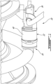
- Fig. 1 illustrates a transfer tube assembly 20 comprising a transfer tube unit 22 fluidly connecting a first component 24 to a second component 26.
- the first component 24 is an inlet nozzle of a gas turbine engine fuel manifold and the second component 26 is a fuel manifold adapter.
- the transfer tube unit 22 could be integrated to a lubricant line, such as an oil feed line of a bearing housing of a gas turbine engine.
- the present disclosure is not limited to gas turbine engines. Indeed, it is understood that the transfer tube unit 22 could be used to fluidly connect various types of components in a wide variety of environments.
- the transfer tube unit 22 comprises at least one transfer tube 28a (e.g. a primary fuel transfer tube) having a rigid tubular body extending along a longitudinal axis A from a first end 30 to a second end 32.
- the tubular body may be made of various materials depending its intended environment of use. For instance, when used as part of a fuel manifold of a gas turbine engine, the transfer tube 28a may be made out of stainless steel.
- the first end 30 of tube 28a is sealingly slidably received in a first bore 34 of the first component 24, whereas the second end 32 of the tube is sealingly slidably received in a second bore 36 of the second component 26.
- Seals such as O-rings 38, may be provided at the first and second ends 30, 32 of the transfer tube 28a for sealing engagement in the bore of the first and second components 24, 26, respectively.
- the O-rings 38 may be removably mounted in corresponding annular seats integrally formed in the outer cylindrical surface of the transfer tube 28a.
- the transfer tube unit 22 further comprises a drain sleeve 40 extending between and sealingly connected at opposite ends to the first and second components 24, 26.
- O-rings 42 may be mounted to the adjacent ends of the first and second components 24, 26 for sealing engagement with the inner cylindrical surface of the sleeve 40, thereby providing for the creation of a sealed cavity 44 around the at least one transfer tube 28a.
- the sealed cavity 44 is configured to trap any fluid that may leak over O-rings 38 at the interface between the transfer tube 28a and the bore of the first and second components 24, 26.
- a return conduit (not shown) may be fluidly connected to the sealed cavity 44 for returning any collected fluid into the fluid system.
- the sleeve 40 acts has an axial retention feature for limiting back and forth movement of the transfer tube 28a relative to the first and second components 24, 26.
- the drain sleeve 40 includes a stopper 48 for engagement with a corresponding shoulder 50 projecting outwardly from an outer surface of the at least one transfer tube 28a.
- the stopper 48 is provided in the form of an annular inner shoulder projecting from the inner surface of the sleeve 40. Still according to some embodiments, the stopper 48 may be engaged in a groove 52 defined in the shoulder 50 of the transfer tube 28a to limit the axial movement of the transfer tube 28a relative to the first and second components 24, 26 in both axial directions.
- the sleeve 40 may be secured in position by securely attaching the sleeve to an adjacent stationary structure (not shown).
- the axial retaining function can be done via a stopper interfacing with the sleeve 40; for instance, in either the sleeve 40 or first or second component 24, 26 grooves 52 for stoppers 48 can be provided which can securely engage the sleeve 40 and limit travel. As shown in Figs. 1 , 3 and 4 , this can be done via a flange 54" extending from an outer surface of the sleeve 40. For instance, holes 56" can be provided in the flange 54" to allow the sleeve 40 to be securely bolted in position.
- the stopper providing the desired axial retention function could be integrated to a component other than the drain sleeve 40 and the drain sleeve could be omitted.
- the stopper could form part of an adjacent stationary structure or it could be provided on the first or second component 24, 26.
- various axial retention arrangements are contemplated beyond the illustrated drain sleeve retention feature.
- the transfer tube shoulder 50 has a conical bore abutment/engaging surface 54 tapering in an axial direction towards the first end 30 of the transfer tube 28a.
- the conical abutment surface 54 defines a slope having an axial component and a radial component relative to the longitudinal axis A.
- the conical abutment surface 54 is received in the entry portion of the first bore 34 of the first component 24. More particularly, the conical abutment surface 54 is disposed in facing relation with the chamfered edge surface 56 circumscribing the entry portion of the first bore 34. Still according to the illustrated embodiment, the surfaces 54, 56 have the same cone angle (i.e. same slope).
- the surfaces 54 and 56 are spaced by a nominal annular gap 58.
- the nominal gap 58 allows for potential misalignment between the first and second components 24, 26. However, if there is high radial/tangential deflection or misalignment due to tolerance stack-up, thermals, pressure deflection, etc., the gap 58 will close and the two surfaces 54,56 will contact each other. Due to the conical profile of the two mating surfaces 54, 56, the reaction forces at the surface interface will generate opposing axial forces, which reduce the resistance to axial sliding allowing the transfer tube 28a to slide at an extremum. This reduces the risk of the transfer tube shoulder 54 interfering with the mating bore in addition to helping sliding movement between the transfer tube 28a and the first component 24.
- the two conical contact surfaces 54, 56 provide for a more even load distribution, which reduces the risk of fretting whenever there is radial interference between the parts. It allows to accommodate thermal growth by not interfering with the back and forth sliding of the transfer tube relative to the first component when the surfaces 54, 56 abut against each other.
- the nominal gap 58 can be greater due to the similar geometric profile of surfaces 54, 56, thereby allowing accommodating greater radial offsets between the first and second components 24, 26. This particularly useful in installation where the transfer tubes are short due to tight envelope constraints.
- the mating shapes and angles of surfaces 54,56 can be different so long as the resulting contact force has an opposing axial component in the transfer tube 28a.
- alternative embodiments entail any geometric shape or cone angles which result in opposing axial components in the transfer tube and which would reduce the resistance to axial sliding in the event of a radial/tangential misalignment.
- Fig. 2 illustrates an example of a second transfer tube 28b (e.g. a secondary fuel transfer tube) having a rounded shoulder profile.
- the bore engagement surface 54' of the transfer tube shoulder 50' extends along a curve having axial and radial components.
- the curved surface 54' is engageable with the conical surface 56' (i.e. the chamfered edge surface) circumscribing the entry of the associated bore 34' in the first component 24.
- the curve of the bore engagement surface 54' is configured to maximise the contact surface between the wall of the bore 34' and the transfer tube 28b.
- transfer tube unit 22 comprises more than one transfer tubes
- transfer tubes may have similar or different shoulder profiles.
- the transfer tube assembly 20 is assembled by first installing the first and second transfer tubes 28a, 28b in the drain sleeve 40.
- the tubes 28a, 28b are axially inserted one by one in the sleeve 40 and engaged in respective seats formed in the inner shoulder acting as the stopper 48.
- the stopper 48 is engaged in overlapping relation with shoulders 50, 50' to limit axial movement of the transfer tubes 28a, 28b.
- this sub-assembly is sequentially slidably axially engaged with the first and second components 24, 26 as shown in Fig. 2 .
- the assembly is completed by securing the drain sleeve 40 in position.
- Fig. 5 illustrates a gas turbine engine 10 with which the transfer tube assembly 20 may be configured.
- the engine 10 is a turboshaft engine generally comprising in serial flow communication a compressor 12 for pressurizing the air, a combustor 16 in which the compressed air is mixed with fuel and ignited for generating an annular stream of hot combustion gases, and a turbine section 18 for extracting energy from the combustion gases.
- the transfer tube assembly 20 may be used in various sections of the engine 10. For instance, it may be used in the engine hot section at location L1 as part of the fuel manifold of the combustor 16. Alternatively, it can be used in the cold section of the engine at location L2 as part of a fluid carrying transfer tube system between engine cases.
- the transfer tube assembly 20 may be included in various engines other than the one described above as well as in other types of equipment.
- it could be used in an aircraft engine, such as a turbofan, a turboprop, a hybrid engine, a compounded engine or an auxiliary power unit to name a few.
Landscapes
- Engineering & Computer Science (AREA)
- General Engineering & Computer Science (AREA)
- Mechanical Engineering (AREA)
- Chemical & Material Sciences (AREA)
- Combustion & Propulsion (AREA)
- Quick-Acting Or Multi-Walled Pipe Joints (AREA)
- Joints Allowing Movement (AREA)
- Gasket Seals (AREA)
Claims (14)
- Übertragungsrohranordnung (20) für ein Flugzeugtriebwerk (10), umfassend:ein erstes Bauteil (24), das eine erste Bohrung (34) aufweist;ein zweites Bauteil (26) das eine zweite Bohrung (36) aufweist; undein Übertragungsrohr (28a, 28b), das das erste Bauteil (24) mit dem zweiten Bauteil (26) fluidisch verbindet, wobei sich das Übertragungsrohr (28a, 28b) entlang einer Längsachse (A) von einem ersten Ende (30) zu einem zweiten Ende (32) erstreckt, wobei das erste Ende (30) abdichtend verschiebbar in der ersten Bohrung (34) des ersten Bauteils (30) aufgenommen ist und das zweite Ende (32) abdichtend verschiebbar in der zweiten Bohrung (36) des zweiten Bauteils (26) aufgenommen ist, wobei das Übertragungsrohr (28a, 28b) eine Schulter (50) aufweist, die von einer Außenfläche davon hervorsteht und mit einem entsprechenden Stopfen (48) zum Begrenzen einer axialen Bewegung des Übertragungsrohrs (28a, 28b) relativ zu dem ersten und dem zweiten Bauteil (24, 26) in Eingriff bringbar ist, wobei die Schulter (50) eine Anschlagfläche (54) aufweist, die einer entsprechenden Bohrungsfläche (56) der ersten Bohrung (34) des ersten Bauteils (30) zugewandt ist, wobei die Anschlagfläche (54) und die Bohrungsfläche (56) entgegengesetzte Axialkräfte entlang der Längsachse (A) als Reaktion darauf erzeugen, dass die Anschlagfläche (54) und die Bohrungsfläche (56) einander kontaktieren, dadurch gekennzeichnet, dass die Übertragungsrohranordnung (20) ferner umfasst:
eine Ablaufhülse (40), die sich zwischen dem ersten und dem zweiten Bauteil (24, 26) erstreckt und an gegenüberliegenden Enden abdichtend mit diesen verbunden ist, wobei das Übertragungsrohr (28a, 28b) in der Ablaufhülse (40) angeordnet ist, wobei der Stopfen (48) eine innere Schulter beinhaltet, die von einer Innenfläche der Ablaufhülse (40) zum Eingriff mit der Schulter (50) des Übertragungsrohrs (28a, 28b) hervorsteht. - Übertragungsrohranordnung (20) nach Anspruch 1, wobei sich die Anschlagfläche (54) und die Bohrungsfläche (56) um die Längsachse (A) herum erstrecken und die Anschlagfläche (54) und die Bohrungsfläche (56) eine Kontaktgrenzfläche aufweisen, wobei die Kontaktgrenzfläche eine axiale Komponente relativ zu der Längsachse (A) aufweist.
- Übertragungsrohranordnung (20) nach Anspruch 1 oder 2, wobei mindestens eine der Anschlagfläche (54) und der Bohrungsfläche (56) konisch ist.
- Übertragungsrohranordnung (20) nach Anspruch 3, wobei sowohl die Anschlagfläche (54) als auch die Bohrungsfläche (56) konisch sind.
- Übertragungsrohranordnung (20) nach Anspruch 3, wobei die Anschlagfläche (54) bei Betrachtung in einem Längsquerschnitt des Übertragungsrohrs (28a, 28b) gekrümmt ist und die Bohrungsfläche (56) konisch ist.
- Übertragungsrohranordnung (20) nach einem der vorhergehenden Ansprüche, wobei jede der Anschlagfläche (54) und der Bohrungsfläche (56) bei Betrachtung in einer sich axial erstreckenden Querschnittsebene eine Neigung relativ zu der Längsachse (A) definieren, wobei die Neigung eine axiale Komponente entlang der Längsachse (A) des Übertragungsrohrs (28a, 28b) aufweist.
- Übertragungsrohranordnung (20) nach einem der vorhergehenden Ansprüche, wobei die Ablaufhülse (40) einen Flansch (54) aufweist, der sich von einer Außenfläche davon zur Anbringung an einer benachbarten stationären Struktur erstreckt.
- Übertragungsrohranordnung (20) nach einem der vorhergehenden Ansprüche, wobei die Bohrungsfläche (56) der ersten Bohrung (34) eine abgeschrägte Kantenfläche (56) an einem Eingang der ersten Bohrung (34) beinhaltet, das Übertragungsrohr (28a, 28b) an dem ersten Ende (30) davon eine Dichtung (38) trägt und die Schulter (50) axial von der Dichtung (38) beabstandet ist und in dem Eingang der ersten Bohrung (34) zum Eingriff mit der abgeschrägten Kantenfläche (56) aufgenommen ist.
- Übertragungsrohranordnung (20) nach einem der vorhergehenden Ansprüche, wobei die Anschlagfläche (54) der Schulter (50) eine konische Fläche beinhaltet und die Bohrungsfläche (56) der ersten Bohrung (34) des ersten Bauteils (24) eine abgeschrägte Kantenfläche beinhaltet, wobei die konische Fläche (54) und die abgeschrägte Kantenfläche (56) durch einen Nennspalt (58) voneinander beabstandet sind.
- Übertragungsrohranordnung (20) nach Anspruch 9, wobei die konische Fläche (54) und die abgeschrägte Kantenfläche (56) den gleichen Konuswinkel aufweisen.
- Übertragungsrohranordnung (20) nach Anspruch 9 oder 10, wobei die konische Fläche (54) und die abgeschrägte Kantenfläche (56) dazu konfiguriert sind, entgegengesetzte axiale Reaktionskräfte relativ zu der Längsachse (A) zu erzeugen, wenn sie gegeneinander gedrückt werden.
- Übertragungsrohranordnung (20) nach einem der vorhergehenden Ansprüche, wobei die Anschlagfläche (54) der Schulter (50) eine Bohrungseingriffsfläche (54) ist, die der Bohrungsfläche (56) des ersten Bauteils (24) zugewandt ist, wobei die Bohrungseingriffsfläche (54) und die Bohrungsfläche (56) eine Kontaktgrenzfläche definieren, die eine axiale Komponente und eine radiale Komponente relativ zu der Längsachse (A) aufweist.
- Übertragungsrohranordnung (20) nach Anspruch 12, wobei die Bohrungsfläche (56) eine abgeschrägte Kantenfläche (56) an dem Eingang der Bohrung (34) ist und wobei die Bohrungseingriffsfläche (54) in dem Eingangsabschnitt der Bohrung (34) aufgenommen ist, wobei sich die abgeschrägte Kantenfläche (56) ringförmig um die Bohrungseingriffsfläche (54) herum erstreckt.
- Übertragungsrohranordnung (20) nach Anspruch 12 oder 13, wobei die Bohrungseingriffsfläche (54) gekrümmt ist.
Applications Claiming Priority (1)
| Application Number | Priority Date | Filing Date | Title |
|---|---|---|---|
| US17/246,836 US11719159B2 (en) | 2021-05-03 | 2021-05-03 | Transfer tube assembly |
Publications (2)
| Publication Number | Publication Date |
|---|---|
| EP4086496A1 EP4086496A1 (de) | 2022-11-09 |
| EP4086496B1 true EP4086496B1 (de) | 2024-06-26 |
Family
ID=81580020
Family Applications (1)
| Application Number | Title | Priority Date | Filing Date |
|---|---|---|---|
| EP22171445.4A Active EP4086496B1 (de) | 2021-05-03 | 2022-05-03 | Übertragungsrohranordnung |
Country Status (3)
| Country | Link |
|---|---|
| US (1) | US11719159B2 (de) |
| EP (1) | EP4086496B1 (de) |
| CA (1) | CA3157077A1 (de) |
Families Citing this family (1)
| Publication number | Priority date | Publication date | Assignee | Title |
|---|---|---|---|---|
| US12241416B2 (en) | 2022-07-04 | 2025-03-04 | Pratt & Whitney Canada Corp. | Adaptor for a fuel system of an aircraft engine |
Family Cites Families (15)
| Publication number | Priority date | Publication date | Assignee | Title |
|---|---|---|---|---|
| US420220A (en) * | 1890-01-28 | Island | ||
| FR2203026B1 (de) * | 1972-10-12 | 1976-01-30 | Europ De Propulsion Fr | |
| US3873134A (en) * | 1973-01-04 | 1975-03-25 | Michael Sammaritano | Apparatus for joining preformed conduits |
| US4066281A (en) | 1976-07-16 | 1978-01-03 | Bonis John C De | Porsche automobile oil drain replacement tube |
| US4482171A (en) * | 1979-01-25 | 1984-11-13 | Campbell Joseph K | Pipe stress/strain neutralizers |
| FR2639702B1 (fr) * | 1988-11-25 | 1991-03-22 | Aerospatiale | Dispositif de raccordement etanche et demontable de deux tubes, notamment pour installation de transfert de carburant |
| US5106129A (en) * | 1990-10-09 | 1992-04-21 | Delaware Capital Formation, Inc. | Flexible coupling for transferring a fluid between two fluid conduits |
| US5261240A (en) | 1992-09-23 | 1993-11-16 | General Electric Company | Fuel shroud system with spherical ferrule/drain can interface |
| US20040032123A1 (en) * | 2002-08-13 | 2004-02-19 | Li-Yun Chu | Angle-adjustable connector |
| FR2934027B1 (fr) * | 2008-07-18 | 2011-03-25 | Thales Sa | Dispositif de regulation de debit d'un fluide et utilisation d'un tel dispositif |
| US8205643B2 (en) | 2008-10-16 | 2012-06-26 | Woodward, Inc. | Multi-tubular fluid transfer conduit |
| US8490409B2 (en) | 2009-10-01 | 2013-07-23 | Pratt & Whitney Canada Corp. | Bleed air transfer tube |
| US9797313B2 (en) | 2014-01-16 | 2017-10-24 | Pratt & Whitney Canada Corp. | Internal manifold with fuel inlet |
| DE102016226019B4 (de) | 2016-12-22 | 2022-12-15 | Mahle International Gmbh | Kupplungselement einer Kurbelgehäuseentlüftungseinrichtung |
| US12123314B2 (en) * | 2020-10-27 | 2024-10-22 | Pratt & Whitney Canada Corp. | Service tube assembly for a gas turbine engine |
-
2021
- 2021-05-03 US US17/246,836 patent/US11719159B2/en active Active
-
2022
- 2022-04-22 CA CA3157077A patent/CA3157077A1/en active Pending
- 2022-05-03 EP EP22171445.4A patent/EP4086496B1/de active Active
Also Published As
| Publication number | Publication date |
|---|---|
| US11719159B2 (en) | 2023-08-08 |
| EP4086496A1 (de) | 2022-11-09 |
| CA3157077A1 (en) | 2022-11-03 |
| US20220349344A1 (en) | 2022-11-03 |
Similar Documents
| Publication | Publication Date | Title |
|---|---|---|
| EP2896862B1 (de) | Befestigung, zugehörige Befestigungsanordnung und Gasturbine | |
| US7000406B2 (en) | Gas turbine combustor sliding joint | |
| US10145256B2 (en) | Aircraft propulsion system seal assembly with spring seal element and compliant seal element | |
| US20110241341A1 (en) | Exhaust pipe for a motor vehicle and exhaust system | |
| US5890746A (en) | Cooled and wetted redundant seal tube fitting | |
| US8490409B2 (en) | Bleed air transfer tube | |
| EP2039976A2 (de) | Flexibles Verbindungsstück für starre Rohranordnung | |
| EP3597869B1 (de) | Dichtungskonfiguration für eine transferröhrenanordnung zur reduzierung von luftleckagen | |
| EP3992434B1 (de) | Betriebsrohranordnung für einen gasturbinenmotor | |
| US6709024B1 (en) | Method and apparatus for assembling couplings for transferring fluids | |
| US20080036209A1 (en) | Assembly including a spring-energized polymeric seal | |
| EP4086496A1 (de) | Übertragungsrohr-baugruppe | |
| EP2816268B1 (de) | Hochdruckrückschlagventilflanschverbindung | |
| EP4306773B1 (de) | Verriegelungsvorrichtung für ein versorgungsrohr | |
| CN112727606B (zh) | 密封组件 | |
| EP3705687A1 (de) | Schieberdichtung | |
| US20060266049A1 (en) | Expansion joint and method of assembling same | |
| US11352896B2 (en) | Tube assembly for a gas turbine engine | |
| CN115405783B (zh) | 管路连接装置和空气管路 | |
| EP3293430B1 (de) | Gelenkige kupplungsanordnung | |
| EP3093544B1 (de) | Selbstzentrierende verschraubte flüssigkeitsverbindung | |
| US6962480B2 (en) | Thermally stabilized turbine scroll retention ring for uniform loading application | |
| US12012872B1 (en) | Service tube locking device | |
| US20220145829A1 (en) | Positive retention expansion joints | |
| EP4245966B1 (de) | Sicherungsvorrichtung für ein servicerohr eines flugzeugtriebwerks |
Legal Events
| Date | Code | Title | Description |
|---|---|---|---|
| PUAI | Public reference made under article 153(3) epc to a published international application that has entered the european phase |
Free format text: ORIGINAL CODE: 0009012 |
|
| STAA | Information on the status of an ep patent application or granted ep patent |
Free format text: STATUS: THE APPLICATION HAS BEEN PUBLISHED |
|
| AK | Designated contracting states |
Kind code of ref document: A1 Designated state(s): AL AT BE BG CH CY CZ DE DK EE ES FI FR GB GR HR HU IE IS IT LI LT LU LV MC MK MT NL NO PL PT RO RS SE SI SK SM TR |
|
| STAA | Information on the status of an ep patent application or granted ep patent |
Free format text: STATUS: REQUEST FOR EXAMINATION WAS MADE |
|
| 17P | Request for examination filed |
Effective date: 20230509 |
|
| RBV | Designated contracting states (corrected) |
Designated state(s): AL AT BE BG CH CY CZ DE DK EE ES FI FR GB GR HR HU IE IS IT LI LT LU LV MC MK MT NL NO PL PT RO RS SE SI SK SM TR |
|
| GRAP | Despatch of communication of intention to grant a patent |
Free format text: ORIGINAL CODE: EPIDOSNIGR1 |
|
| STAA | Information on the status of an ep patent application or granted ep patent |
Free format text: STATUS: GRANT OF PATENT IS INTENDED |
|
| RIC1 | Information provided on ipc code assigned before grant |
Ipc: F16L 39/04 20060101ALI20231208BHEP Ipc: F16L 51/00 20060101ALI20231208BHEP Ipc: F16L 27/12 20060101AFI20231208BHEP |
|
| INTG | Intention to grant announced |
Effective date: 20240104 |
|
| GRAS | Grant fee paid |
Free format text: ORIGINAL CODE: EPIDOSNIGR3 |
|
| GRAA | (expected) grant |
Free format text: ORIGINAL CODE: 0009210 |
|
| STAA | Information on the status of an ep patent application or granted ep patent |
Free format text: STATUS: THE PATENT HAS BEEN GRANTED |
|
| AK | Designated contracting states |
Kind code of ref document: B1 Designated state(s): AL AT BE BG CH CY CZ DE DK EE ES FI FR GB GR HR HU IE IS IT LI LT LU LV MC MK MT NL NO PL PT RO RS SE SI SK SM TR |
|
| REG | Reference to a national code |
Ref country code: GB Ref legal event code: FG4D |
|
| REG | Reference to a national code |
Ref country code: CH Ref legal event code: EP |
|
| REG | Reference to a national code |
Ref country code: DE Ref legal event code: R096 Ref document number: 602022004103 Country of ref document: DE |
|
| PG25 | Lapsed in a contracting state [announced via postgrant information from national office to epo] |
Ref country code: BG Free format text: LAPSE BECAUSE OF FAILURE TO SUBMIT A TRANSLATION OF THE DESCRIPTION OR TO PAY THE FEE WITHIN THE PRESCRIBED TIME-LIMIT Effective date: 20240626 |
|
| PG25 | Lapsed in a contracting state [announced via postgrant information from national office to epo] |
Ref country code: FI Free format text: LAPSE BECAUSE OF FAILURE TO SUBMIT A TRANSLATION OF THE DESCRIPTION OR TO PAY THE FEE WITHIN THE PRESCRIBED TIME-LIMIT Effective date: 20240626 Ref country code: HR Free format text: LAPSE BECAUSE OF FAILURE TO SUBMIT A TRANSLATION OF THE DESCRIPTION OR TO PAY THE FEE WITHIN THE PRESCRIBED TIME-LIMIT Effective date: 20240626 |
|
| REG | Reference to a national code |
Ref country code: LT Ref legal event code: MG9D |
|
| PG25 | Lapsed in a contracting state [announced via postgrant information from national office to epo] |
Ref country code: GR Free format text: LAPSE BECAUSE OF FAILURE TO SUBMIT A TRANSLATION OF THE DESCRIPTION OR TO PAY THE FEE WITHIN THE PRESCRIBED TIME-LIMIT Effective date: 20240927 |
|
| PG25 | Lapsed in a contracting state [announced via postgrant information from national office to epo] |
Ref country code: LV Free format text: LAPSE BECAUSE OF FAILURE TO SUBMIT A TRANSLATION OF THE DESCRIPTION OR TO PAY THE FEE WITHIN THE PRESCRIBED TIME-LIMIT Effective date: 20240626 |
|
| REG | Reference to a national code |
Ref country code: NL Ref legal event code: MP Effective date: 20240626 |
|
| PG25 | Lapsed in a contracting state [announced via postgrant information from national office to epo] |
Ref country code: NO Free format text: LAPSE BECAUSE OF FAILURE TO SUBMIT A TRANSLATION OF THE DESCRIPTION OR TO PAY THE FEE WITHIN THE PRESCRIBED TIME-LIMIT Effective date: 20240926 Ref country code: LV Free format text: LAPSE BECAUSE OF FAILURE TO SUBMIT A TRANSLATION OF THE DESCRIPTION OR TO PAY THE FEE WITHIN THE PRESCRIBED TIME-LIMIT Effective date: 20240626 Ref country code: HR Free format text: LAPSE BECAUSE OF FAILURE TO SUBMIT A TRANSLATION OF THE DESCRIPTION OR TO PAY THE FEE WITHIN THE PRESCRIBED TIME-LIMIT Effective date: 20240626 Ref country code: GR Free format text: LAPSE BECAUSE OF FAILURE TO SUBMIT A TRANSLATION OF THE DESCRIPTION OR TO PAY THE FEE WITHIN THE PRESCRIBED TIME-LIMIT Effective date: 20240927 Ref country code: FI Free format text: LAPSE BECAUSE OF FAILURE TO SUBMIT A TRANSLATION OF THE DESCRIPTION OR TO PAY THE FEE WITHIN THE PRESCRIBED TIME-LIMIT Effective date: 20240626 Ref country code: BG Free format text: LAPSE BECAUSE OF FAILURE TO SUBMIT A TRANSLATION OF THE DESCRIPTION OR TO PAY THE FEE WITHIN THE PRESCRIBED TIME-LIMIT Effective date: 20240626 Ref country code: RS Free format text: LAPSE BECAUSE OF FAILURE TO SUBMIT A TRANSLATION OF THE DESCRIPTION OR TO PAY THE FEE WITHIN THE PRESCRIBED TIME-LIMIT Effective date: 20240926 |
|
| PG25 | Lapsed in a contracting state [announced via postgrant information from national office to epo] |
Ref country code: NL Free format text: LAPSE BECAUSE OF FAILURE TO SUBMIT A TRANSLATION OF THE DESCRIPTION OR TO PAY THE FEE WITHIN THE PRESCRIBED TIME-LIMIT Effective date: 20240626 |
|
| REG | Reference to a national code |
Ref country code: AT Ref legal event code: MK05 Ref document number: 1697974 Country of ref document: AT Kind code of ref document: T Effective date: 20240626 |
|
| PG25 | Lapsed in a contracting state [announced via postgrant information from national office to epo] |
Ref country code: NL Free format text: LAPSE BECAUSE OF FAILURE TO SUBMIT A TRANSLATION OF THE DESCRIPTION OR TO PAY THE FEE WITHIN THE PRESCRIBED TIME-LIMIT Effective date: 20240626 |
|
| PG25 | Lapsed in a contracting state [announced via postgrant information from national office to epo] |
Ref country code: PT Free format text: LAPSE BECAUSE OF FAILURE TO SUBMIT A TRANSLATION OF THE DESCRIPTION OR TO PAY THE FEE WITHIN THE PRESCRIBED TIME-LIMIT Effective date: 20241028 |
|
| PG25 | Lapsed in a contracting state [announced via postgrant information from national office to epo] |
Ref country code: PT Free format text: LAPSE BECAUSE OF FAILURE TO SUBMIT A TRANSLATION OF THE DESCRIPTION OR TO PAY THE FEE WITHIN THE PRESCRIBED TIME-LIMIT Effective date: 20241028 |
|
| PG25 | Lapsed in a contracting state [announced via postgrant information from national office to epo] |
Ref country code: PL Free format text: LAPSE BECAUSE OF FAILURE TO SUBMIT A TRANSLATION OF THE DESCRIPTION OR TO PAY THE FEE WITHIN THE PRESCRIBED TIME-LIMIT Effective date: 20240626 |
|
| PG25 | Lapsed in a contracting state [announced via postgrant information from national office to epo] |
Ref country code: EE Free format text: LAPSE BECAUSE OF FAILURE TO SUBMIT A TRANSLATION OF THE DESCRIPTION OR TO PAY THE FEE WITHIN THE PRESCRIBED TIME-LIMIT Effective date: 20240626 |
|
| PG25 | Lapsed in a contracting state [announced via postgrant information from national office to epo] |
Ref country code: IS Free format text: LAPSE BECAUSE OF FAILURE TO SUBMIT A TRANSLATION OF THE DESCRIPTION OR TO PAY THE FEE WITHIN THE PRESCRIBED TIME-LIMIT Effective date: 20241026 Ref country code: AT Free format text: LAPSE BECAUSE OF FAILURE TO SUBMIT A TRANSLATION OF THE DESCRIPTION OR TO PAY THE FEE WITHIN THE PRESCRIBED TIME-LIMIT Effective date: 20240626 |
|
| PG25 | Lapsed in a contracting state [announced via postgrant information from national office to epo] |
Ref country code: CZ Free format text: LAPSE BECAUSE OF FAILURE TO SUBMIT A TRANSLATION OF THE DESCRIPTION OR TO PAY THE FEE WITHIN THE PRESCRIBED TIME-LIMIT Effective date: 20240626 |
|
| PG25 | Lapsed in a contracting state [announced via postgrant information from national office to epo] |
Ref country code: RO Free format text: LAPSE BECAUSE OF FAILURE TO SUBMIT A TRANSLATION OF THE DESCRIPTION OR TO PAY THE FEE WITHIN THE PRESCRIBED TIME-LIMIT Effective date: 20240626 Ref country code: SK Free format text: LAPSE BECAUSE OF FAILURE TO SUBMIT A TRANSLATION OF THE DESCRIPTION OR TO PAY THE FEE WITHIN THE PRESCRIBED TIME-LIMIT Effective date: 20240626 |
|
| PG25 | Lapsed in a contracting state [announced via postgrant information from national office to epo] |
Ref country code: SM Free format text: LAPSE BECAUSE OF FAILURE TO SUBMIT A TRANSLATION OF THE DESCRIPTION OR TO PAY THE FEE WITHIN THE PRESCRIBED TIME-LIMIT Effective date: 20240626 Ref country code: ES Free format text: LAPSE BECAUSE OF FAILURE TO SUBMIT A TRANSLATION OF THE DESCRIPTION OR TO PAY THE FEE WITHIN THE PRESCRIBED TIME-LIMIT Effective date: 20240626 |
|
| PG25 | Lapsed in a contracting state [announced via postgrant information from national office to epo] |
Ref country code: SM Free format text: LAPSE BECAUSE OF FAILURE TO SUBMIT A TRANSLATION OF THE DESCRIPTION OR TO PAY THE FEE WITHIN THE PRESCRIBED TIME-LIMIT Effective date: 20240626 Ref country code: SK Free format text: LAPSE BECAUSE OF FAILURE TO SUBMIT A TRANSLATION OF THE DESCRIPTION OR TO PAY THE FEE WITHIN THE PRESCRIBED TIME-LIMIT Effective date: 20240626 Ref country code: RO Free format text: LAPSE BECAUSE OF FAILURE TO SUBMIT A TRANSLATION OF THE DESCRIPTION OR TO PAY THE FEE WITHIN THE PRESCRIBED TIME-LIMIT Effective date: 20240626 Ref country code: PL Free format text: LAPSE BECAUSE OF FAILURE TO SUBMIT A TRANSLATION OF THE DESCRIPTION OR TO PAY THE FEE WITHIN THE PRESCRIBED TIME-LIMIT Effective date: 20240626 Ref country code: IS Free format text: LAPSE BECAUSE OF FAILURE TO SUBMIT A TRANSLATION OF THE DESCRIPTION OR TO PAY THE FEE WITHIN THE PRESCRIBED TIME-LIMIT Effective date: 20241026 Ref country code: ES Free format text: LAPSE BECAUSE OF FAILURE TO SUBMIT A TRANSLATION OF THE DESCRIPTION OR TO PAY THE FEE WITHIN THE PRESCRIBED TIME-LIMIT Effective date: 20240626 Ref country code: EE Free format text: LAPSE BECAUSE OF FAILURE TO SUBMIT A TRANSLATION OF THE DESCRIPTION OR TO PAY THE FEE WITHIN THE PRESCRIBED TIME-LIMIT Effective date: 20240626 Ref country code: CZ Free format text: LAPSE BECAUSE OF FAILURE TO SUBMIT A TRANSLATION OF THE DESCRIPTION OR TO PAY THE FEE WITHIN THE PRESCRIBED TIME-LIMIT Effective date: 20240626 Ref country code: AT Free format text: LAPSE BECAUSE OF FAILURE TO SUBMIT A TRANSLATION OF THE DESCRIPTION OR TO PAY THE FEE WITHIN THE PRESCRIBED TIME-LIMIT Effective date: 20240626 |
|
| PG25 | Lapsed in a contracting state [announced via postgrant information from national office to epo] |
Ref country code: IT Free format text: LAPSE BECAUSE OF FAILURE TO SUBMIT A TRANSLATION OF THE DESCRIPTION OR TO PAY THE FEE WITHIN THE PRESCRIBED TIME-LIMIT Effective date: 20240626 |
|
| REG | Reference to a national code |
Ref country code: DE Ref legal event code: R097 Ref document number: 602022004103 Country of ref document: DE |
|
| PG25 | Lapsed in a contracting state [announced via postgrant information from national office to epo] |
Ref country code: DK Free format text: LAPSE BECAUSE OF FAILURE TO SUBMIT A TRANSLATION OF THE DESCRIPTION OR TO PAY THE FEE WITHIN THE PRESCRIBED TIME-LIMIT Effective date: 20240626 |
|
| PLBE | No opposition filed within time limit |
Free format text: ORIGINAL CODE: 0009261 |
|
| STAA | Information on the status of an ep patent application or granted ep patent |
Free format text: STATUS: NO OPPOSITION FILED WITHIN TIME LIMIT |
|
| 26N | No opposition filed |
Effective date: 20250327 |
|
| PG25 | Lapsed in a contracting state [announced via postgrant information from national office to epo] |
Ref country code: SE Free format text: LAPSE BECAUSE OF FAILURE TO SUBMIT A TRANSLATION OF THE DESCRIPTION OR TO PAY THE FEE WITHIN THE PRESCRIBED TIME-LIMIT Effective date: 20240626 |
|
| REG | Reference to a national code |
Ref country code: CH Ref legal event code: H13 Free format text: ST27 STATUS EVENT CODE: U-0-0-H10-H13 (AS PROVIDED BY THE NATIONAL OFFICE) Effective date: 20251223 |
|
| PG25 | Lapsed in a contracting state [announced via postgrant information from national office to epo] |
Ref country code: LU Free format text: LAPSE BECAUSE OF NON-PAYMENT OF DUE FEES Effective date: 20250503 |
|
| PG25 | Lapsed in a contracting state [announced via postgrant information from national office to epo] |
Ref country code: CH Free format text: LAPSE BECAUSE OF NON-PAYMENT OF DUE FEES Effective date: 20250531 |
|
| REG | Reference to a national code |
Ref country code: BE Ref legal event code: MM Effective date: 20250531 |
|
| PG25 | Lapsed in a contracting state [announced via postgrant information from national office to epo] |
Ref country code: MC Free format text: LAPSE BECAUSE OF FAILURE TO SUBMIT A TRANSLATION OF THE DESCRIPTION OR TO PAY THE FEE WITHIN THE PRESCRIBED TIME-LIMIT Effective date: 20240626 |
|
| PG25 | Lapsed in a contracting state [announced via postgrant information from national office to epo] |
Ref country code: IE Free format text: LAPSE BECAUSE OF NON-PAYMENT OF DUE FEES Effective date: 20250503 |
|
| PG25 | Lapsed in a contracting state [announced via postgrant information from national office to epo] |
Ref country code: BE Free format text: LAPSE BECAUSE OF NON-PAYMENT OF DUE FEES Effective date: 20250531 |
|
| PG25 | Lapsed in a contracting state [announced via postgrant information from national office to epo] |
Ref country code: LT Free format text: LAPSE BECAUSE OF FAILURE TO SUBMIT A TRANSLATION OF THE DESCRIPTION OR TO PAY THE FEE WITHIN THE PRESCRIBED TIME-LIMIT Effective date: 20240626 |
|
| PGFP | Annual fee paid to national office [announced via postgrant information from national office to epo] |
Ref country code: GB Payment date: 20260421 Year of fee payment: 5 |
|
| PGFP | Annual fee paid to national office [announced via postgrant information from national office to epo] |
Ref country code: DE Payment date: 20260421 Year of fee payment: 5 |
|
| PGFP | Annual fee paid to national office [announced via postgrant information from national office to epo] |
Ref country code: FR Payment date: 20260421 Year of fee payment: 5 |
|
| PG25 | Lapsed in a contracting state [announced via postgrant information from national office to epo] |
Ref country code: CY Free format text: LAPSE BECAUSE OF FAILURE TO SUBMIT A TRANSLATION OF THE DESCRIPTION OR TO PAY THE FEE WITHIN THE PRESCRIBED TIME-LIMIT Effective date: 20240626 |