EP2816285B1 - Doppel-venturi-düse für eine verbrennungsvorrichtung - Google Patents
Doppel-venturi-düse für eine verbrennungsvorrichtung Download PDFInfo
- Publication number
- EP2816285B1 EP2816285B1 EP13748985.2A EP13748985A EP2816285B1 EP 2816285 B1 EP2816285 B1 EP 2816285B1 EP 13748985 A EP13748985 A EP 13748985A EP 2816285 B1 EP2816285 B1 EP 2816285B1
- Authority
- EP
- European Patent Office
- Prior art keywords
- damper
- secondary gas
- inlet pipe
- moving body
- gas inlet
- Prior art date
- Legal status (The legal status is an assumption and is not a legal conclusion. Google has not performed a legal analysis and makes no representation as to the accuracy of the status listed.)
- Active
Links
Images


Classifications
-
- F—MECHANICAL ENGINEERING; LIGHTING; HEATING; WEAPONS; BLASTING
- F23—COMBUSTION APPARATUS; COMBUSTION PROCESSES
- F23D—BURNERS
- F23D14/00—Burners for combustion of a gas, e.g. of a gas stored under pressure as a liquid
- F23D14/02—Premix gas burners, i.e. in which gaseous fuel is mixed with combustion air upstream of the combustion zone
- F23D14/04—Premix gas burners, i.e. in which gaseous fuel is mixed with combustion air upstream of the combustion zone induction type, e.g. Bunsen burner
-
- F—MECHANICAL ENGINEERING; LIGHTING; HEATING; WEAPONS; BLASTING
- F23—COMBUSTION APPARATUS; COMBUSTION PROCESSES
- F23D—BURNERS
- F23D14/00—Burners for combustion of a gas, e.g. of a gas stored under pressure as a liquid
- F23D14/46—Details
-
- F—MECHANICAL ENGINEERING; LIGHTING; HEATING; WEAPONS; BLASTING
- F23—COMBUSTION APPARATUS; COMBUSTION PROCESSES
- F23D—BURNERS
- F23D14/00—Burners for combustion of a gas, e.g. of a gas stored under pressure as a liquid
- F23D14/46—Details
- F23D14/60—Devices for simultaneous control of gas and combustion air
-
- F—MECHANICAL ENGINEERING; LIGHTING; HEATING; WEAPONS; BLASTING
- F23—COMBUSTION APPARATUS; COMBUSTION PROCESSES
- F23D—BURNERS
- F23D14/00—Burners for combustion of a gas, e.g. of a gas stored under pressure as a liquid
- F23D14/46—Details
- F23D14/62—Mixing devices; Mixing tubes
-
- F—MECHANICAL ENGINEERING; LIGHTING; HEATING; WEAPONS; BLASTING
- F23—COMBUSTION APPARATUS; COMBUSTION PROCESSES
- F23N—REGULATING OR CONTROLLING COMBUSTION
- F23N1/00—Regulating fuel supply
- F23N1/02—Regulating fuel supply conjointly with air supply
- F23N1/027—Regulating fuel supply conjointly with air supply using mechanical means
-
- F—MECHANICAL ENGINEERING; LIGHTING; HEATING; WEAPONS; BLASTING
- F23—COMBUSTION APPARATUS; COMBUSTION PROCESSES
- F23N—REGULATING OR CONTROLLING COMBUSTION
- F23N5/00—Systems for controlling combustion
Definitions
- the present invention relates to a dual venturi for a combustion apparatus, and more particularly, to a dual venturi for a combustion apparatus, capable of effectively controlling a heating value since respective amounts of gas and air supplied to a burner provided in a water heater are controlled in a two-step manner and a motor is coupled to a damper so that the damper simultaneously opens or closes inlets for secondary air and gas along with rotation of the damper by driving of the motor.
- a venturi device for a combustion apparatus according to the preamble of claim 1 is disclosed in document US 20110139045A1 .
- combustion apparatuses such as boilers and water heaters for the purpose of use of heating and hot water are classified into an oil boiler, a gas boiler, an electric boiler and a water heater depending on the fuel it is supplied with, and are variously developed and used according to installation applications.
- the gas boiler and the water heater typically use a bunsen burner or a premixed burner to burn gas fuel.
- the premixed burner among others has a combustion method of mixing gas and air in a mixing ratio for optimal combustion and then supplying a mixture (air + gas) to a flame hole section so that the mixture is burned.
- the performance of the combustion apparatuses is evaluated as a TDR (Turn-Down Ratio).
- the TDR refers to "a ratio of maximum gas consumption to minimum gas consumption" in a gas combustion device in which an amount of gas is variably controlled. For example, when the maximum gas consumption is 24,000 kcal/h and the minimum gas consumption is 8,000 kcal/h, the TDR is 3:1.
- the TDR is constrained by whether flame is stably maintained to some degree under minimum gas consumption.
- valves allowing for supply of gas are mainly classified into an electrical modulating gas valve controlled by current values and a pneumatic modulating gas valve controlled by differential pressures generated during supply of air.
- the pneumatic modulating gas valve controls an amount of gas supplied to the burner by differential pressures generated when air required for combustion is supplied to the burner by a blower.
- air and gas required for combustion are mixed in a gas-air mixer and then supplied to the burner in a mixture (air + gas) form.
- the TDR is basically constrained by a factor such as a relation between gas consumption Q and differential pressure ⁇ P.
- the ratio of pressure differences has to be defined as 9:1 for defining the TDR as 3:1 and the ratio of pressure differences has to be defined as 100:1 for defining the TDR as 10:1.
- the ratio of pressure differences has to be defined as 9:1 for defining the TDR as 3:1 and the ratio of pressure differences has to be defined as 100:1 for defining the TDR as 10:1.
- the present invention has been made in view of the above problems, and it is an object of the present invention to provide a dual venturi for a combustion apparatus, capable of effectively controlling inflow and outflow of secondary gas and air by allowing a secondary gas passage to be connected to or blocked from a secondary air duct according to a rotation angle of a damper.
- a dual venturi for a combustion apparatus includes the features of the preamble of claim 1.
- the damper and the secondary gas inlet pipe may include an opening and closing unit configured of two or more first protrusion pieces protrudingly formed at an inner side of a central portion of the damper, a moving body moving upward or downward along an inner peripheral surface of the secondary gas inlet pipe along with rotation of the damper, the moving body having second protrusion pieces formed to engage with the first protrusion pieces and a recessed portion formed on an outer peripheral surface thereof so that the secondary gas flows in an inner wall of the secondary gas inlet pipe, a spring for elastically supporting the moving body, and a spring fixing portion coupled to an upper portion of the moving body to support the spring, the spring fixing portion having a recessed portion formed on a circumference thereof so as to form a passage so that the secondary gas flows in the inner wall of the secondary gas inlet pipe, and the flow of the secondary gas may be blocked when the second protrusion pieces of the moving body engage with the first protrusion pieces.
- the moving body may further include a sealing member for sealing a portion coming into contact with the secondary gas inlet pipe.
- the secondary gas may flow between an inner wall surface of the secondary gas inlet pipe and the recessed portions formed at the moving body and the spring fixing portion.
- the motor may be a synchronous motor.
- heating values such as low heating values or high heating values may be selectively generated by a water heater as necessary and a user may control the heating values such as low heating values or high heating values as necessary. Therefore, fuel costs may be reduced.
- an inner portion of a housing is divided by a partition wall to form a primary passage and a secondary passage so that only primary air and gas flow in the primary passage and only secondary air and gas flow in the secondary passage. Therefore, it may be possible to easily adjust a TDR by regulating the flows of air and gas in the secondary passage.
- a damper opens and closed a secondary gas outlet and simultaneously opens and closes the secondary passage along with rotation thereof, a structure may be significantly simplified.
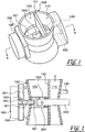
- FIG. 1 is a perspective view illustrating a dual venturi for a combustion apparatus according to an embodiment of the present invention.
- FIG. 2 is a cross-sectional view taken along line A-A and illustrates a state in which a damper closes a secondary passage.
- FIG. 3 is a cross-sectional view illustrating a state in which the damper opens the secondary passage in FIG. 2 .
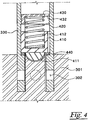
- FIG. 4 is a cross-sectional view illustrating a state in which an opening and closing unit provided in a secondary gas inlet pipe blocks the secondary passage in FIG. 2 .
- FIG. 5 is a cross-sectional view illustrating a state in which the secondary passage is opened by rotation of the opening and closing unit in FIG. 4 .
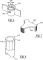
- FIG. 6 is a perspective view illustrating the damper of FIG. 4 .
- FIG. 7 is a perspective view illustrating a spring fixing portion of the opening and closing unit in FIG. 4 .
- FIG. 8 is a perspective view illustrating a moving body of the opening and closing
- the dual venturi for a combustion apparatus includes a housing 100 which is divided by a partition wall 101 to have a primary passage 110 and a secondary passage 120 and has a primary gas inlet pipe 130 formed at a middle on a side wall cf the primary passage 110.
- the secondary passage 120 of the housing 100 is provided with a damper 301 which is provided therein to open and close the flow of secondary air when the damper 301 is rotated and is formed with a damper hole 303.
- the damper 301 is coupled to a secondary gas inlet pipe 330 and the secondary gas inlet pipe 330 passes through a middle portion of the housing 100 to be coupled with the damper 301.
- the secondary gas inlet pipe 330 has a secondary gas outlet 302 formed at an end thereof and the secondary gas outlet 302 is formed to be located on the same line as the damper hole 303.
- the secondary gas outlet 302 has a structure of communicating with the damper hole 303 according to a rotation angle of the damper 301.
- the housing 100 is further provided, at an outer side thereof, with a motor 180 for rotating the damper 301 by coupling of a rotary shaft 181 and the damper 301.
- the motor 180 provides torque to the damper 301.
- the rotary shaft 181 has protrusions 182 formed at intervals of 90 degrees and the protrusions 182 operate a limit switch 201 along with rotation of the motor 180 such that the rotation angle of the damper 301 is controlled.
- the limit switch 201 is provided inside a switch box 200 and the switch box 200 is interposed between the housing 100 and the motor 180.
- the damper 301 has first protrusion pieces 401 which are protrudingly formed at an inner side of a central portion thereof.
- the first protrusion pieces 401 are symmetrically formed at a distal end of a cylindrical member 402 formed integrally with the damper 301.
- the secondary gas inlet pipe 330 is coupled with a moving body 410 having recessed portions 412 which are formed on an outer peripheral surface thereof so as to correspond to the first protrusion pieces 401.
- the moving body 410 has second protrusion pieces 411 formed to engage with the first protrusion pieces 401. Accordingly, when the first protrusion pieces 401 engage with the second protrusion pieces 411, a cylindrical shape without a gap is formed.
- the first and second protrusion pieces 401 and 411 are formed in the same shape, and cross-sectional portions thereof have a flexible curved surface such that the first and second protrusion pieces 401 and 411 are easily coupled to and decoupled from each other.
- an upper portion of the moving body 410 is coupled with a spring fixing portion 430 which has a recessed portion 412 formed on an outer peripheral surface thereof and is screw-coupled to the secondary gas inlet pipe 330.
- a spring 420 is interposed between the moving 410 and the spring fixing portion 430 so as to elastically support the moving body 410.
- the moving body 410 is further provided with a sealing member 440 for sealing a portion coming into contact with the secondary gas inlet pipe 330.
- the portion at which the moving body 410 comes into contact with the secondary gas inlet pipe 330 is formed in a stepped shape, and the sealing member 440 is coupled to the stepped portion.
- a combustion apparatus may be actuated by means of a low heating value.
- the secondary gas is introduced through the secondary gas inlet pipe 330 and through the respective recessed portions 412 and 432 formed on the outer peripheral surfaces of the spring fixing portion 430 and the moving body 410, and then passes through the secondary gas outlet 302 and the damper hole 303 (as indicated by a dotted arrow), so as to be introduced into the secondary passage 120.
- the secondary gas is mixed with the air and gas introduced through the primary passage 110 and the primary gas inlet pipe 130 so that a large amount of mixture is generated and the mixture is introduced into the turbofan.
- the combustion apparatus may be actuated by means of a high heating value.
- the damper 301 is returned to the state shown in FIGS. 2 and 4 . Consequently, the secondary passage 120 and the secondary gas outlet 302 are blocked and, as such, the combustion apparatus is actuated by means of a low heating value.
- the spring 420 interposed between the moving body 410 and the spring fixing portion 430 serves to block the secondary gas from being introduced by moving the moving body 410 toward the damper 301 using restoring force of the spring 420 when the damper 301 is rotated to close the secondary gas outlet 302 and by pressing the outer surface of the moving body 410 against the sealing member 440.
- the rotary shaft 181 of the motor 180 has the protrusions 182 which are protrudingly formed on an outer peripheral surface thereof at intervals of 90 degrees and the limit switch 201 has movable protrusions 202 formed to be located on the same circumference as the protrusions 182.
- the limit switch 201 causes a short circuit current and, as such, rotation of the motor 180 is stopped.
- the combustion apparatus when the combustion apparatus is actuated, the protrusions 182 are rotated by 90 degrees to press the movable protrusions 202. Then, the limit switch 201 is turned off to stop rotation of the motor 180 and the damper 301 is also stopped. As a result, the secondary passage 120 is opened or closed.
Landscapes
- Engineering & Computer Science (AREA)
- Chemical & Material Sciences (AREA)
- Combustion & Propulsion (AREA)
- Mechanical Engineering (AREA)
- General Engineering & Computer Science (AREA)
- Feeding And Controlling Fuel (AREA)
- Regulation And Control Of Combustion (AREA)
- Gas Burners (AREA)
Claims (5)
- Ein Doppel- Venturi einer Verbrennungsmaschine umfasst:ein Gehäuse (100), welches als zylindrische Leitung ausgebildet ist, und welches mittels einer Trennwand (101) in einen ersten Durchgang (110) und einen zweiten Durchgang (120) aufgeteilt ist, und welches eine erste Gaseinlassleitung (130) aufweist, die an einem Seitenteil des ersten Durchgangs (110) vorgesehen ist, eine zweite Gaseinlassleitung (330), die einen zweiten Gasauslass (302) aufweist, wobei ein zweites Gas in das Gegenende der zweiten Gaseinlassleitung (330) eingeführt ist,eine Klappe (301), welche innerhalb des zweiten Durchgangs (120) des Gehäuses (100) vorgesehen ist, um den Fluss des zweiten Gases durch Verdrehen der Klappe (301) zu öffnen und zu schließen,dadurch gekennzeichnet, dass die Klappe (301) eine Klappenöffnung (303) aufweist,die zweite Gaseinlassleitung (330) ein Ende aufweist, welches mit der Klappe (301) verbunden ist und den zweiten Gasauslass (302) am gleichen Umfang wie die Klappenöffnung (303) aufweist, der zweite Gasauslass (302) selektiv mit der Klappenöffnung (303) in Bezug auf den Drehwinkel der Klappe (301) verbindbar ist;und ein Motor (180) außerhalb des Gehäuses (100) vorgesehen ist, der eine drehbare Welle (181) aufweist, die mit der Klappe (301) derart verbunden ist, dass die Klappe (301) verdreht wird.
- Ein Doppel- Venturi nach Anspruch 1, wobei die Klappe (301) und die zweite Gaseinlassleitung (330) folgendes aufweisen:zwei oder mehr erste Vorsprünge (401), die an einer Innenseite eines Mittelteils der Klappe (301) vorstehend ausgebildet sind;einen bewegbaren Körper (410), der entlang einer inneren Umfangsfläche der zweiten Gaseinlassleitung (330) auf- und abbewegt werden kann, indem die Klappe (301) verdreht wird, wobei der bewegbare Körper (410) zweite Vorsprünge (411) aufweist, welche an den ersten Vorsprüngen (401) angreifen, sowie einem Rücksprung (412), welcher an der äußeren Umfangsfläche vorgesehen ist, so dass das zweite Gas an einer Innenwand der zweiten Gaseingangsleitung (330) strömt;eine Feder (420) zur elastischen Abstützung des bewegbaren Teils (410);und einen Federhalter (430), welcher an einem oberen Bereich des bewegbaren Körpers (410) gekoppelt ist, um die Feder (420) abzustützen, wobei der Federhalter (430) einen Rücksprung (432) aufweist, welcher an einem Außenumfang desselben vorgesehen ist, um einen Durchlass zu bilden, so dass das zweite Gas an einer Innenwand der zweiten Eingangsgasleitung (330) strömt,wobei die Strömung des zweiten Gases blockiert ist, wenn die zweiten Vorsprünge (411) des bewegbaren Körpers (410) in Anlage mit den ersten Vorsprüngen kommen.
- Doppel-Venturi nach Anspruch 2, wobei der bewegbare Körper (410) außerdem ein Dichtelement (440) zum Abdichten eines Bereichs aufweist, der in Kontakt mit der zweiten Eingangsgasleitung (330) steht.
- Doppel-Venturi nach Anspruch 1 oder 2, wobei für den Fall, dass der bewegbare Körper (410) durch Verdrehung der Klappe (301) aufwärts bewegt wird, die zweiten Vorsprünge (411) mit den ersten Vorsprüngen (401) mit ihren entsprechenden Seiten in Kontakt zueinander stehen, in eine Lage verstellt werden, in der entsprechende Kuppenteile miteinander in Kontakt stehen, so dass das zweite Gas zwischen der Innenwand der zweiten Eingangsgasleitung (330) und dem Rücksprung (412, 432), welcher am bewegbaren Körper (410) und am Federhalter (430) angeformt ist, strömt.
- Doppel-Venturi nach Anspruch 1, wobei der Motor (180) ein Synchronmotor ist.
Applications Claiming Priority (2)
| Application Number | Priority Date | Filing Date | Title |
|---|---|---|---|
| KR1020120015097A KR101259764B1 (ko) | 2012-02-15 | 2012-02-15 | 연소기기용 듀얼 벤츄리 |
| PCT/KR2013/000429 WO2013122332A1 (ko) | 2012-02-15 | 2013-01-18 | 연소기기용 듀얼 벤츄리 |
Publications (3)
| Publication Number | Publication Date |
|---|---|
| EP2816285A1 EP2816285A1 (de) | 2014-12-24 |
| EP2816285A4 EP2816285A4 (de) | 2015-12-02 |
| EP2816285B1 true EP2816285B1 (de) | 2016-07-06 |
Family
ID=48665277
Family Applications (1)
| Application Number | Title | Priority Date | Filing Date |
|---|---|---|---|
| EP13748985.2A Active EP2816285B1 (de) | 2012-02-15 | 2013-01-18 | Doppel-venturi-düse für eine verbrennungsvorrichtung |
Country Status (8)
| Country | Link |
|---|---|
| US (1) | US10393370B2 (de) |
| EP (1) | EP2816285B1 (de) |
| JP (1) | JP5893763B2 (de) |
| KR (1) | KR101259764B1 (de) |
| CN (1) | CN104114945B (de) |
| AU (1) | AU2013221124B2 (de) |
| ES (1) | ES2582710T3 (de) |
| WO (1) | WO2013122332A1 (de) |
Families Citing this family (11)
| Publication number | Priority date | Publication date | Assignee | Title |
|---|---|---|---|---|
| KR101320113B1 (ko) * | 2012-02-28 | 2013-10-18 | 주식회사 경동나비엔 | 온수기용 듀얼 벤추리 |
| KR101448992B1 (ko) * | 2013-04-16 | 2014-10-13 | 주식회사 경동나비엔 | 연소기기용 듀얼 벤츄리 |
| US10823400B2 (en) * | 2014-01-09 | 2020-11-03 | A.O. Smith Corporation | Multi-cavity gas and air mixing device |
| JP6050281B2 (ja) * | 2014-06-06 | 2016-12-21 | リンナイ株式会社 | 予混合装置 |
| USD807466S1 (en) * | 2015-03-06 | 2018-01-09 | Michael S. Adkins | Semi-submersible gas burner |
| KR102428535B1 (ko) * | 2017-12-29 | 2022-08-03 | 주식회사 경동나비엔 | 연관식 보일러 |
| CN112128758B (zh) * | 2019-06-25 | 2025-07-29 | 芜湖美的厨卫电器制造有限公司 | 文丘里管、预混装置和燃气设备 |
| CN111828977B (zh) | 2020-07-16 | 2025-02-14 | 广东万和新电气股份有限公司 | 一种防倒流预混器及燃气热水器 |
| CN111828975B (zh) * | 2020-07-16 | 2025-12-09 | 广东万和新电气股份有限公司 | 一种适配多气源的预混器及燃气热水器 |
| KR102543014B1 (ko) * | 2021-06-29 | 2023-06-13 | 린나이코리아 주식회사 | 가스보일러용 벤츄리장치 |
| KR20240083673A (ko) * | 2022-12-05 | 2024-06-12 | 주식회사 경동나비엔 | 듀얼 벤추리 |
Family Cites Families (19)
| Publication number | Priority date | Publication date | Assignee | Title |
|---|---|---|---|---|
| US1493894A (en) * | 1919-04-04 | 1924-05-13 | Frank A Reece | Carburetor |
| US1737496A (en) * | 1923-02-15 | 1929-11-26 | Feroldi Enrico | Carburetor |
| US1936993A (en) * | 1931-05-14 | 1933-11-28 | Dempson H Reed | Speed control device |
| US2995349A (en) * | 1960-01-22 | 1961-08-08 | Sr Walter L Kennedy | Fuel injector |
| US3220709A (en) * | 1962-12-14 | 1965-11-30 | Thadie H Pickron | Device for supplying a fuel and air mixture to internal combustion engines |
| JPS5730656U (de) * | 1980-07-25 | 1982-02-18 | ||
| US4572809A (en) * | 1982-12-17 | 1986-02-25 | Bothwell Peter W | Carburettor |
| US4526729A (en) * | 1983-01-26 | 1985-07-02 | Braun Alfred J | Vortex carburetor |
| JPS59200118A (ja) * | 1983-04-27 | 1984-11-13 | Matsushita Electric Ind Co Ltd | 燃料空気混合装置 |
| US5439619A (en) * | 1993-12-09 | 1995-08-08 | Keystone International Holdings Corp. | Steam conditioning butterfly valve |
| JP3144359B2 (ja) | 1997-09-30 | 2001-03-12 | 三浦工業株式会社 | 予混合式ガスバーナの燃料ガス量制御装置 |
| US5971026A (en) | 1997-12-09 | 1999-10-26 | Honeywell Inc. | Internal geometry shape design for venturi tube-like gas-air mixing valve |
| JP2001173949A (ja) * | 1999-12-16 | 2001-06-29 | Harman Co Ltd | 燃焼装置 |
| KR100365652B1 (ko) | 2000-10-30 | 2002-12-26 | 주식회사 경동보일러 | 가스보일러 송풍기용 오리피스 믹서 |
| US7143993B2 (en) * | 2003-01-17 | 2006-12-05 | Siemens Vdo Automotive, Inc. | Exhaust gas recirculation valve having a rotary motor |
| KR100669884B1 (ko) | 2004-09-25 | 2007-01-18 | 주식회사 롯데기공 | 가스연료연소용 예혼합기 |
| KR200387916Y1 (ko) | 2005-03-19 | 2005-06-29 | 장기풍 | 가스버너용 혼합기 조절장치 |
| ITBO20080278A1 (it) | 2008-04-30 | 2009-11-01 | Gas Point S R L | Bruciatore a gas a pre-miscelazione |
| ITBO20100441A1 (it) * | 2010-07-12 | 2012-01-13 | Gas Point S R L | Bruciatore a gas a pre-miscelazione |
-
2012
- 2012-02-15 KR KR1020120015097A patent/KR101259764B1/ko active Active
-
2013
- 2013-01-18 AU AU2013221124A patent/AU2013221124B2/en active Active
- 2013-01-18 EP EP13748985.2A patent/EP2816285B1/de active Active
- 2013-01-18 ES ES13748985.2T patent/ES2582710T3/es active Active
- 2013-01-18 JP JP2014556471A patent/JP5893763B2/ja not_active Expired - Fee Related
- 2013-01-18 US US14/378,970 patent/US10393370B2/en active Active
- 2013-01-18 CN CN201380009512.8A patent/CN104114945B/zh active Active
- 2013-01-18 WO PCT/KR2013/000429 patent/WO2013122332A1/ko not_active Ceased
Also Published As
| Publication number | Publication date |
|---|---|
| AU2013221124A1 (en) | 2014-08-28 |
| WO2013122332A1 (ko) | 2013-08-22 |
| CN104114945B (zh) | 2016-06-29 |
| CN104114945A (zh) | 2014-10-22 |
| ES2582710T3 (es) | 2016-09-14 |
| US20150056564A1 (en) | 2015-02-26 |
| EP2816285A1 (de) | 2014-12-24 |
| JP2015510100A (ja) | 2015-04-02 |
| US10393370B2 (en) | 2019-08-27 |
| JP5893763B2 (ja) | 2016-03-23 |
| AU2013221124B2 (en) | 2015-10-01 |
| KR101259764B1 (ko) | 2013-05-07 |
| EP2816285A4 (de) | 2015-12-02 |
Similar Documents
| Publication | Publication Date | Title |
|---|---|---|
| EP2816285B1 (de) | Doppel-venturi-düse für eine verbrennungsvorrichtung | |
| EP2988066B1 (de) | Doppelventuri für eine verbrennungsvorrichtung | |
| EP2816286A1 (de) | Doppel-venturi-düse für eine brennkammer | |
| JP5948440B2 (ja) | 燃焼機器用ガス‐空気混合装置 | |
| EP2824390B1 (de) | Gas-luftmischvorrichtung für verbrennungsvorrichtung | |
| EP2927585B1 (de) | Doppel-venturi-düse für eine brennkammer |
Legal Events
| Date | Code | Title | Description |
|---|---|---|---|
| PUAI | Public reference made under article 153(3) epc to a published international application that has entered the european phase |
Free format text: ORIGINAL CODE: 0009012 |
|
| 17P | Request for examination filed |
Effective date: 20140905 |
|
| AK | Designated contracting states |
Kind code of ref document: A1 Designated state(s): AL AT BE BG CH CY CZ DE DK EE ES FI FR GB GR HR HU IE IS IT LI LT LU LV MC MK MT NL NO PL PT RO RS SE SI SK SM TR |
|
| AX | Request for extension of the european patent |
Extension state: BA ME |
|
| DAX | Request for extension of the european patent (deleted) | ||
| RA4 | Supplementary search report drawn up and despatched (corrected) |
Effective date: 20151030 |
|
| RIC1 | Information provided on ipc code assigned before grant |
Ipc: F23N 5/00 20060101ALI20151026BHEP Ipc: F23D 14/62 20060101ALI20151026BHEP Ipc: F23N 1/02 20060101ALI20151026BHEP Ipc: F23D 14/60 20060101ALI20151026BHEP Ipc: F23D 14/46 20060101AFI20151026BHEP |
|
| GRAP | Despatch of communication of intention to grant a patent |
Free format text: ORIGINAL CODE: EPIDOSNIGR1 |
|
| INTG | Intention to grant announced |
Effective date: 20160125 |
|
| GRAS | Grant fee paid |
Free format text: ORIGINAL CODE: EPIDOSNIGR3 |
|
| GRAA | (expected) grant |
Free format text: ORIGINAL CODE: 0009210 |
|
| AK | Designated contracting states |
Kind code of ref document: B1 Designated state(s): AL AT BE BG CH CY CZ DE DK EE ES FI FR GB GR HR HU IE IS IT LI LT LU LV MC MK MT NL NO PL PT RO RS SE SI SK SM TR |
|
| REG | Reference to a national code |
Ref country code: GB Ref legal event code: FG4D |
|
| REG | Reference to a national code |
Ref country code: AT Ref legal event code: REF Ref document number: 810994 Country of ref document: AT Kind code of ref document: T Effective date: 20160715 Ref country code: CH Ref legal event code: EP |
|
| REG | Reference to a national code |
Ref country code: IE Ref legal event code: FG4D |
|
| REG | Reference to a national code |
Ref country code: DE Ref legal event code: R096 Ref document number: 602013009192 Country of ref document: DE |
|
| REG | Reference to a national code |
Ref country code: ES Ref legal event code: FG2A Ref document number: 2582710 Country of ref document: ES Kind code of ref document: T3 Effective date: 20160914 |
|
| REG | Reference to a national code |
Ref country code: NL Ref legal event code: FP |
|
| REG | Reference to a national code |
Ref country code: LT Ref legal event code: MG4D |
|
| REG | Reference to a national code |
Ref country code: AT Ref legal event code: MK05 Ref document number: 810994 Country of ref document: AT Kind code of ref document: T Effective date: 20160706 |
|
| PG25 | Lapsed in a contracting state [announced via postgrant information from national office to epo] |
Ref country code: FI Free format text: LAPSE BECAUSE OF FAILURE TO SUBMIT A TRANSLATION OF THE DESCRIPTION OR TO PAY THE FEE WITHIN THE PRESCRIBED TIME-LIMIT Effective date: 20160706 Ref country code: NO Free format text: LAPSE BECAUSE OF FAILURE TO SUBMIT A TRANSLATION OF THE DESCRIPTION OR TO PAY THE FEE WITHIN THE PRESCRIBED TIME-LIMIT Effective date: 20161006 Ref country code: IS Free format text: LAPSE BECAUSE OF FAILURE TO SUBMIT A TRANSLATION OF THE DESCRIPTION OR TO PAY THE FEE WITHIN THE PRESCRIBED TIME-LIMIT Effective date: 20161106 Ref country code: HR Free format text: LAPSE BECAUSE OF FAILURE TO SUBMIT A TRANSLATION OF THE DESCRIPTION OR TO PAY THE FEE WITHIN THE PRESCRIBED TIME-LIMIT Effective date: 20160706 Ref country code: RS Free format text: LAPSE BECAUSE OF FAILURE TO SUBMIT A TRANSLATION OF THE DESCRIPTION OR TO PAY THE FEE WITHIN THE PRESCRIBED TIME-LIMIT Effective date: 20160706 Ref country code: LT Free format text: LAPSE BECAUSE OF FAILURE TO SUBMIT A TRANSLATION OF THE DESCRIPTION OR TO PAY THE FEE WITHIN THE PRESCRIBED TIME-LIMIT Effective date: 20160706 |
|
| PG25 | Lapsed in a contracting state [announced via postgrant information from national office to epo] |
Ref country code: AT Free format text: LAPSE BECAUSE OF FAILURE TO SUBMIT A TRANSLATION OF THE DESCRIPTION OR TO PAY THE FEE WITHIN THE PRESCRIBED TIME-LIMIT Effective date: 20160706 Ref country code: SE Free format text: LAPSE BECAUSE OF FAILURE TO SUBMIT A TRANSLATION OF THE DESCRIPTION OR TO PAY THE FEE WITHIN THE PRESCRIBED TIME-LIMIT Effective date: 20160706 Ref country code: BE Free format text: LAPSE BECAUSE OF FAILURE TO SUBMIT A TRANSLATION OF THE DESCRIPTION OR TO PAY THE FEE WITHIN THE PRESCRIBED TIME-LIMIT Effective date: 20160706 Ref country code: PL Free format text: LAPSE BECAUSE OF FAILURE TO SUBMIT A TRANSLATION OF THE DESCRIPTION OR TO PAY THE FEE WITHIN THE PRESCRIBED TIME-LIMIT Effective date: 20160706 Ref country code: GR Free format text: LAPSE BECAUSE OF FAILURE TO SUBMIT A TRANSLATION OF THE DESCRIPTION OR TO PAY THE FEE WITHIN THE PRESCRIBED TIME-LIMIT Effective date: 20161007 Ref country code: LV Free format text: LAPSE BECAUSE OF FAILURE TO SUBMIT A TRANSLATION OF THE DESCRIPTION OR TO PAY THE FEE WITHIN THE PRESCRIBED TIME-LIMIT Effective date: 20160706 Ref country code: PT Free format text: LAPSE BECAUSE OF FAILURE TO SUBMIT A TRANSLATION OF THE DESCRIPTION OR TO PAY THE FEE WITHIN THE PRESCRIBED TIME-LIMIT Effective date: 20161107 |
|
| REG | Reference to a national code |
Ref country code: DE Ref legal event code: R097 Ref document number: 602013009192 Country of ref document: DE |
|
| PG25 | Lapsed in a contracting state [announced via postgrant information from national office to epo] |
Ref country code: RO Free format text: LAPSE BECAUSE OF FAILURE TO SUBMIT A TRANSLATION OF THE DESCRIPTION OR TO PAY THE FEE WITHIN THE PRESCRIBED TIME-LIMIT Effective date: 20160706 Ref country code: EE Free format text: LAPSE BECAUSE OF FAILURE TO SUBMIT A TRANSLATION OF THE DESCRIPTION OR TO PAY THE FEE WITHIN THE PRESCRIBED TIME-LIMIT Effective date: 20160706 |
|
| PLBE | No opposition filed within time limit |
Free format text: ORIGINAL CODE: 0009261 |
|
| STAA | Information on the status of an ep patent application or granted ep patent |
Free format text: STATUS: NO OPPOSITION FILED WITHIN TIME LIMIT |
|
| PG25 | Lapsed in a contracting state [announced via postgrant information from national office to epo] |
Ref country code: BG Free format text: LAPSE BECAUSE OF FAILURE TO SUBMIT A TRANSLATION OF THE DESCRIPTION OR TO PAY THE FEE WITHIN THE PRESCRIBED TIME-LIMIT Effective date: 20161006 Ref country code: SK Free format text: LAPSE BECAUSE OF FAILURE TO SUBMIT A TRANSLATION OF THE DESCRIPTION OR TO PAY THE FEE WITHIN THE PRESCRIBED TIME-LIMIT Effective date: 20160706 Ref country code: DK Free format text: LAPSE BECAUSE OF FAILURE TO SUBMIT A TRANSLATION OF THE DESCRIPTION OR TO PAY THE FEE WITHIN THE PRESCRIBED TIME-LIMIT Effective date: 20160706 Ref country code: CZ Free format text: LAPSE BECAUSE OF FAILURE TO SUBMIT A TRANSLATION OF THE DESCRIPTION OR TO PAY THE FEE WITHIN THE PRESCRIBED TIME-LIMIT Effective date: 20160706 Ref country code: SM Free format text: LAPSE BECAUSE OF FAILURE TO SUBMIT A TRANSLATION OF THE DESCRIPTION OR TO PAY THE FEE WITHIN THE PRESCRIBED TIME-LIMIT Effective date: 20160706 |
|
| 26N | No opposition filed |
Effective date: 20170407 |
|
| PG25 | Lapsed in a contracting state [announced via postgrant information from national office to epo] |
Ref country code: SI Free format text: LAPSE BECAUSE OF FAILURE TO SUBMIT A TRANSLATION OF THE DESCRIPTION OR TO PAY THE FEE WITHIN THE PRESCRIBED TIME-LIMIT Effective date: 20160706 |
|
| REG | Reference to a national code |
Ref country code: CH Ref legal event code: PL |
|
| PG25 | Lapsed in a contracting state [announced via postgrant information from national office to epo] |
Ref country code: MC Free format text: LAPSE BECAUSE OF FAILURE TO SUBMIT A TRANSLATION OF THE DESCRIPTION OR TO PAY THE FEE WITHIN THE PRESCRIBED TIME-LIMIT Effective date: 20160706 |
|
| REG | Reference to a national code |
Ref country code: FR Ref legal event code: ST Effective date: 20170929 |
|
| PG25 | Lapsed in a contracting state [announced via postgrant information from national office to epo] |
Ref country code: FR Free format text: LAPSE BECAUSE OF NON-PAYMENT OF DUE FEES Effective date: 20170131 Ref country code: LI Free format text: LAPSE BECAUSE OF NON-PAYMENT OF DUE FEES Effective date: 20170131 Ref country code: CH Free format text: LAPSE BECAUSE OF NON-PAYMENT OF DUE FEES Effective date: 20170131 |
|
| REG | Reference to a national code |
Ref country code: IE Ref legal event code: MM4A |
|
| PG25 | Lapsed in a contracting state [announced via postgrant information from national office to epo] |
Ref country code: LU Free format text: LAPSE BECAUSE OF NON-PAYMENT OF DUE FEES Effective date: 20170118 |
|
| PG25 | Lapsed in a contracting state [announced via postgrant information from national office to epo] |
Ref country code: IE Free format text: LAPSE BECAUSE OF NON-PAYMENT OF DUE FEES Effective date: 20170118 |
|
| PG25 | Lapsed in a contracting state [announced via postgrant information from national office to epo] |
Ref country code: MT Free format text: LAPSE BECAUSE OF NON-PAYMENT OF DUE FEES Effective date: 20170118 |
|
| PG25 | Lapsed in a contracting state [announced via postgrant information from national office to epo] |
Ref country code: AL Free format text: LAPSE BECAUSE OF FAILURE TO SUBMIT A TRANSLATION OF THE DESCRIPTION OR TO PAY THE FEE WITHIN THE PRESCRIBED TIME-LIMIT Effective date: 20160706 |
|
| PG25 | Lapsed in a contracting state [announced via postgrant information from national office to epo] |
Ref country code: HU Free format text: LAPSE BECAUSE OF FAILURE TO SUBMIT A TRANSLATION OF THE DESCRIPTION OR TO PAY THE FEE WITHIN THE PRESCRIBED TIME-LIMIT; INVALID AB INITIO Effective date: 20130118 |
|
| PG25 | Lapsed in a contracting state [announced via postgrant information from national office to epo] |
Ref country code: CY Free format text: LAPSE BECAUSE OF FAILURE TO SUBMIT A TRANSLATION OF THE DESCRIPTION OR TO PAY THE FEE WITHIN THE PRESCRIBED TIME-LIMIT Effective date: 20160706 |
|
| PG25 | Lapsed in a contracting state [announced via postgrant information from national office to epo] |
Ref country code: MK Free format text: LAPSE BECAUSE OF FAILURE TO SUBMIT A TRANSLATION OF THE DESCRIPTION OR TO PAY THE FEE WITHIN THE PRESCRIBED TIME-LIMIT Effective date: 20160706 |
|
| PG25 | Lapsed in a contracting state [announced via postgrant information from national office to epo] |
Ref country code: TR Free format text: LAPSE BECAUSE OF FAILURE TO SUBMIT A TRANSLATION OF THE DESCRIPTION OR TO PAY THE FEE WITHIN THE PRESCRIBED TIME-LIMIT Effective date: 20160706 |
|
| PGFP | Annual fee paid to national office [announced via postgrant information from national office to epo] |
Ref country code: DE Payment date: 20220105 Year of fee payment: 10 |
|
| PGFP | Annual fee paid to national office [announced via postgrant information from national office to epo] |
Ref country code: NL Payment date: 20220118 Year of fee payment: 10 |
|
| REG | Reference to a national code |
Ref country code: DE Ref legal event code: R119 Ref document number: 602013009192 Country of ref document: DE |
|
| REG | Reference to a national code |
Ref country code: NL Ref legal event code: MM Effective date: 20230201 |
|
| PG25 | Lapsed in a contracting state [announced via postgrant information from national office to epo] |
Ref country code: NL Free format text: LAPSE BECAUSE OF NON-PAYMENT OF DUE FEES Effective date: 20230201 Ref country code: DE Free format text: LAPSE BECAUSE OF NON-PAYMENT OF DUE FEES Effective date: 20230801 |
|
| PGFP | Annual fee paid to national office [announced via postgrant information from national office to epo] |
Ref country code: GB Payment date: 20251204 Year of fee payment: 14 |
|
| PGFP | Annual fee paid to national office [announced via postgrant information from national office to epo] |
Ref country code: ES Payment date: 20260209 Year of fee payment: 14 |
|
| PGFP | Annual fee paid to national office [announced via postgrant information from national office to epo] |
Ref country code: IT Payment date: 20251219 Year of fee payment: 14 |