EP2816360B1 - Berechnungsverfahren einer elektrischen Messgröße, Transformatoreinheit, die ein solches System umfasst, und Berechnungsverfahren einer elektrischen Messgröße mit einem solchen System - Google Patents
Berechnungsverfahren einer elektrischen Messgröße, Transformatoreinheit, die ein solches System umfasst, und Berechnungsverfahren einer elektrischen Messgröße mit einem solchen System Download PDFInfo
- Publication number
- EP2816360B1 EP2816360B1 EP14172570.5A EP14172570A EP2816360B1 EP 2816360 B1 EP2816360 B1 EP 2816360B1 EP 14172570 A EP14172570 A EP 14172570A EP 2816360 B1 EP2816360 B1 EP 2816360B1
- Authority
- EP
- European Patent Office
- Prior art keywords
- module
- message
- calculating
- intensity
- measured
- Prior art date
- Legal status (The legal status is an assumption and is not a legal conclusion. Google has not performed a legal analysis and makes no representation as to the accuracy of the status listed.)
- Active
Links
Images





Classifications
-
- G—PHYSICS
- G01—MEASURING; TESTING
- G01R—MEASURING ELECTRIC VARIABLES; MEASURING MAGNETIC VARIABLES
- G01R19/00—Arrangements for measuring currents or voltages or for indicating presence or sign thereof
- G01R19/25—Arrangements for measuring currents or voltages or for indicating presence or sign thereof using digital measurement techniques
-
- H—ELECTRICITY
- H02—GENERATION; CONVERSION OR DISTRIBUTION OF ELECTRIC POWER
- H02J—ELECTRIC POWER NETWORKS; CIRCUIT ARRANGEMENTS OR SYSTEMS FOR SUPPLYING OR DISTRIBUTING ELECTRIC POWER; SYSTEMS FOR STORING ELECTRIC ENERGY
- H02J13/00—Circuit arrangements for providing remote monitoring or remote control of equipment in a power distribution network
- H02J13/13—Circuit arrangements for providing remote monitoring or remote control of equipment in a power distribution network characterised by the transmission of data to equipment in the power network
- H02J13/1337—Circuit arrangements for providing remote monitoring or remote control of equipment in a power distribution network characterised by the transmission of data to equipment in the power network involving the use of Internet protocols
-
- G—PHYSICS
- G01—MEASURING; TESTING
- G01D—MEASURING NOT SPECIALLY ADAPTED FOR A SPECIFIC VARIABLE; ARRANGEMENTS FOR MEASURING TWO OR MORE VARIABLES NOT COVERED IN A SINGLE OTHER SUBCLASS; TARIFF METERING APPARATUS; MEASURING OR TESTING NOT OTHERWISE PROVIDED FOR
- G01D4/00—Tariff metering apparatus
- G01D4/002—Remote reading of utility meters
-
- G—PHYSICS
- G01—MEASURING; TESTING
- G01R—MEASURING ELECTRIC VARIABLES; MEASURING MAGNETIC VARIABLES
- G01R19/00—Arrangements for measuring currents or voltages or for indicating presence or sign thereof
- G01R19/25—Arrangements for measuring currents or voltages or for indicating presence or sign thereof using digital measurement techniques
- G01R19/2513—Arrangements for monitoring electric power systems, e.g. power lines or loads; Logging
-
- H—ELECTRICITY
- H02—GENERATION; CONVERSION OR DISTRIBUTION OF ELECTRIC POWER
- H02J—ELECTRIC POWER NETWORKS; CIRCUIT ARRANGEMENTS OR SYSTEMS FOR SUPPLYING OR DISTRIBUTING ELECTRIC POWER; SYSTEMS FOR STORING ELECTRIC ENERGY
- H02J13/00—Circuit arrangements for providing remote monitoring or remote control of equipment in a power distribution network
- H02J13/18—Circuit arrangements for providing remote monitoring or remote control of equipment in a power distribution network characterised by the remotely-controlled equipment, e.g. converters or transformers
- H02J13/333—Circuit arrangements for providing remote monitoring or remote control of equipment in a power distribution network characterised by the remotely-controlled equipment, e.g. converters or transformers the equipment forming part of substations
-
- Y—GENERAL TAGGING OF NEW TECHNOLOGICAL DEVELOPMENTS; GENERAL TAGGING OF CROSS-SECTIONAL TECHNOLOGIES SPANNING OVER SEVERAL SECTIONS OF THE IPC; TECHNICAL SUBJECTS COVERED BY FORMER USPC CROSS-REFERENCE ART COLLECTIONS [XRACs] AND DIGESTS
- Y02—TECHNOLOGIES OR APPLICATIONS FOR MITIGATION OR ADAPTATION AGAINST CLIMATE CHANGE
- Y02E—REDUCTION OF GREENHOUSE GAS [GHG] EMISSIONS, RELATED TO ENERGY GENERATION, TRANSMISSION OR DISTRIBUTION
- Y02E60/00—Enabling technologies; Technologies with a potential or indirect contribution to GHG emissions mitigation
-
- Y—GENERAL TAGGING OF NEW TECHNOLOGICAL DEVELOPMENTS; GENERAL TAGGING OF CROSS-SECTIONAL TECHNOLOGIES SPANNING OVER SEVERAL SECTIONS OF THE IPC; TECHNICAL SUBJECTS COVERED BY FORMER USPC CROSS-REFERENCE ART COLLECTIONS [XRACs] AND DIGESTS
- Y04—INFORMATION OR COMMUNICATION TECHNOLOGIES HAVING AN IMPACT ON OTHER TECHNOLOGY AREAS
- Y04S—SYSTEMS INTEGRATING TECHNOLOGIES RELATED TO POWER NETWORK OPERATION, COMMUNICATION OR INFORMATION TECHNOLOGIES FOR IMPROVING THE ELECTRICAL POWER GENERATION, TRANSMISSION, DISTRIBUTION, MANAGEMENT OR USAGE, i.e. SMART GRIDS
- Y04S10/00—Systems supporting electrical power generation, transmission or distribution
- Y04S10/16—Electric power substations
Definitions
- the present invention also relates to a station for transforming an electric current having a first alternating voltage into an electric current having a second alternating voltage, this transformer station comprising such a calculation system.
- the present invention also relates to a method for calculating an electrical quantity with such a calculation system.
- the calculation system comprises modules for calculating electrical energy or electrical power, a database for storing the calculated values of the energy or power and a management module capable of providing, to remote clients, information corresponding to the measured and calculated values.
- the calculation modules are connected via radio links to a communication gateway itself connected to a network.
- the database, the management module and the remote clients are also connected to the network.
- Each calculation module is capable of calculating the electrical energy and the power of the current flowing in an electrical conductor. It comprises an intensity sensor, a processing unit capable of calculating the electrical energy and power and a radio transceiver.
- Each calculation module is synchronized with the communication gateway via a clock.
- the aim of the invention is therefore to propose a system for calculating an electrical quantity of the intensity, energy or electrical power type for an electrical conductor with which no current sensor is associated.
- the invention makes it possible, for example, in an electrical installation comprising a primary electrical conductor and several secondary electrical conductors, to measure the electrical intensity in all the secondary electrical conductors and to calculate the electrical intensity in the primary conductor from these measured values.
- the invention relates to a calculation system according to claim 1.
- the calculation system further comprises one or more of the optional features of claims 2 to 9:
- the invention also relates to a transformer station according to claim 10.
- the invention also relates to a calculation method according to claim 11.
- the calculation method further comprises one or more of the optional features of claims 12 to 15.
- the quasi-simultaneous measurement of the intensity by each current sensor of each second module makes it possible to carry out operations, such as additions, on the different instantaneous complex intensities measured, as well as on instantaneous complex powers and/or on energies calculated, among other things, from the different intensities measured.
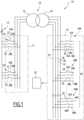
- a transformer station 10 connected to an electrical network 12 comprises a first panel 14, a second panel 16, an electrical transformer 18 connected between the first panel 14 and the second panel 16 and a system 20 for calculating an electrical quantity such as electrical energy, electrical power or electrical intensity.
- the transformer station 10 is capable of transforming the electric current delivered by the network 12 and having a first alternating voltage, into an electric current having a second alternating voltage.
- the electrical network 12 is an alternating network, such as a three-phase network.
- the electrical network 12 is a medium voltage network, that is to say a network whose voltage is greater than 1000 volts and less than 50000 volts.
- the first three-phase voltage is then a medium voltage.
- the electrical network 12 is a high voltage network, that is, a network whose voltage is greater than 50,000 volts.
- the first three-phase voltage is a high voltage.
- the first panel 14 comprises several arrivals 22A, 22B, each arrival 22A, 22B comprising a first 24A, 24B, a second 26A, 26B, and a third 28A, 28B arrival conductors.
- Each first, second, third arrival conductor 24A, 24B, 26A, 26B, 28A, 28B is connected to the electrical network via a respective arrival circuit breaker 32.
- the three-phase current flowing in the corresponding arrival conductors 24A, 24B, 26A, 26B, 28A, 28B has the first three-phase voltage.
- the second panel 16 comprises a first 34, a second 36, a third 38 and a fourth 39 primary conductor and a plurality N of departures 40A, 40B, ... 40N, namely a first departure 40A, a second departure 40B, ..., an Nth departure 40N, each departure 40A, 40B, ..., 40N being capable of delivering a three-phase voltage.
- Each 40A, 40B, ..., 40N outlet is a low voltage outlet, i.e. an outlet with a voltage lower than 1000 volts.
- the second three-phase voltage is then a low voltage.
- each 40A, 40B, ..., 40N outlet is a medium voltage outlet, i.e. an outlet with a voltage greater than 1000 volts and less than 50000 volts.
- the second three-phase voltage is a medium voltage.
- the first feeder 40A comprises a first 42A, a second 44A, a third 46A and a fourth 48A secondary conductors and three feeder circuit breakers 50.
- the first, second and third secondary conductors 42A, 44A, 46A are respectively connected to the first, second and third primary conductors 34, 36, 38 via a corresponding feeder circuit breaker 50.
- the fourth secondary conductor 48A is directly connected to the fourth primary conductor 39.
- the primary outgoing conductors 34, 36, 38, and the corresponding secondary outgoing conductors 42A, 44A, 46A have substantially the same voltage, namely respectively a first voltage V1, a second voltage V2 and a third voltage V3 corresponding to the three phases of the second three-phase voltage relative to the neutral conductor 39.
- the other departures 40B, ..., 40N are identical to the first departure 40A described above, and include the same elements, each time replacing the letter A with the corresponding letter B, ..., N concerning the references of the elements.
- the electrical transformer 18 is capable of transforming the current from the electrical network having the first alternating voltage into the current delivered to the second panel 16 and having the second alternating voltage.
- the electrical transformer 18 comprises a primary winding 52 connected to the first panel 14 and a secondary winding 54 connected to the second panel 16.
- the calculation system 20 is capable of calculating an electrical quantity of the intensity, electrical energy and/or instantaneous electrical power type in each secondary outgoing conductor 42A, 44A, 46A, 48A, 42B, 44B, 46B, 48B..., 42N, 44N, 46N, 48N.
- the second table 16 is represented with the number N of departures equal to 3.
- the second table 16 includes a first 34, a second 36, a third 38 and a fourth 39 primary conductors and three departures 40A, 40B, 40C.
- the calculation system 20 comprises a first module 60 connected to the primary conductors 34, 36, 38, 39, three second modules 62A, 62B, 62C, namely a second module 62A, 62B, 62C respectively for each departure 40A, 40B, 40C, the second module 62A, 62B, 62C being connected to the secondary departure conductors 42A, 44A, 46A, respectively 42B, 44B, 46B and respectively 44C, 46C, 46C.
- the calculation system 20 comprises a third module 63.
- the first module 60 comprises a measuring device 66, a radio transmitter 70, a radio antenna 72, a microcontroller 74, a communication block 80 and a device 82 for supplying electricity to these different elements.
- the second module 62A comprises, for each of the first 42A, second 44A and third 46A secondary conductors, a current sensor 83A capable of measuring the intensity of the current flowing in the corresponding secondary conductor 42A, 44A, 46A. It additionally comprises a microcontroller 84A, a radio transmitter-receiver 86A, a radio antenna 88A, an analog-digital converter 90A and a power supply member 92A for these elements.
- the other second modules 62B, 62C are identical to the second module 62A described above, and comprise the same elements, each time replacing the letter A with the corresponding letter B, C concerning the references of the elements.
- the third module 63 comprises a radio receiver 101, a radio antenna 102, a calculation unit 104, a data storage and time-stamping unit 105, a human-machine interface 106, a communication block 107 and a unit 108 for supplying electricity to these different elements.
- the measuring member 66 is suitable for measuring the frequency F of the three-phase voltage of the primary conductors 34, 36, 38.
- the radio transmitter 70 preferably complies with the ZIGBEE or ZIGBEE GREEN POWER communication protocol based on the IEEE-802.15.4 standard.
- the radio transmitter 70 preferably complies with the IEEE-802.15.1 standard or the IEEE-802.15.2 standard.
- the radio transmitter 70 preferably complies with the IEEE-802-11 standard. Without complying with an IEEE standard, this transmitter can also simply comply with the regulations in force in each country (proprietary radio communication solution).
- the radio antenna 72 is adapted to transmit radio signals to the antennas 88A, 88B, 88C of the second modules 62A, 62B, 62C.
- the first module 60 is connected to each of the second modules 62A, 62B, 62C by a corresponding radio link.
- the microcontroller 74 is capable of storing and executing software, not shown, for transmitting a first message M1 to each second module 62A, 62B, 62C, the transmission software being capable of cooperating with the radio transmitter 70 and the radio antenna 72.
- the communication block 80 allows communication of the first module 60 with an external organ, not shown, using a communication link, preferably standardized, such as a link of the ModBus Serial Line Protocol type, or ModBus TCP/IP or any other protocol using IP.
- the current sensor 83A is capable of measuring a respective intensity among a first intensity IA1 flowing in the first secondary outgoing conductor 42A, a second intensity IA2 flowing in the second secondary outgoing conductor 44A and a third intensity IA3 flowing in the third secondary outgoing conductor 46A.
- analog-digital converter 90A is capable of sampling, according to a sampling frequency F ECH , the values of the intensity IA1, IA2, IA3 measured by the current sensor 83A.
- analog-digital converter 90A, as well as the analog-digital converters 90B and 90C also form a sampling device.
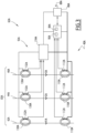
- the current sensor 83A comprises a first torus 110A arranged around the corresponding secondary outgoing conductor 42A, 44A, 46A and a first winding 112A arranged around the first torus, as shown in the figure 3 .
- the flow of current through the corresponding secondary outgoing conductor is capable of generating an induced current proportional to the intensity of the current in the first winding 112A.
- the first torus 110A is a Rogowski torus.
- the first torus 110A is preferably an opening torus in order to facilitate its arrangement around the corresponding conductors.
- the microcontroller 84A is capable of storing and executing software for acquiring the values sampled by the analog-digital converter 90A of the respective intensities IA1, IA2, IA3, software for receiving the first message M1, software for compressing the sampled values of the first, second and third intensities IA1, IA2, IA3 and software for transmitting a second message M2A to the third module 63, not shown.
- the 86A radio transceiver is of the same type as the 70 radio transmitter.
- the radio antenna 88A is adapted to receive radio signals from the antenna 72 and also to transmit radio signals to the antenna 101.
- the power supply member 92A of the second module 62A comprises, for each of the first 42A, second 44A and third 46A secondary conductors, a second torus 130A arranged around the corresponding secondary conductor 42A, 44A, 46A and a second winding 132A arranged around the second torus.
- the flow of current in the corresponding secondary conductor 42A, 44A, 46A is capable of generating an induced current in the second winding 132A.
- the second module 62A is self-powered by each second torus 130A and each second winding 132A, which recover the magnetic energy and form a current transformer.
- the power supply member 92A comprises a converter 134A connected to each of the second windings 132A and capable of delivering a predetermined voltage to the radio transceiver 86A, to the microcontroller 84A and to the analog-digital converter 90A.
- Each second toroid 130A is an iron toroid.
- Each second toroid 130A is preferably an opening toroid in order to facilitate its arrangement around the corresponding conductors.
- the secondary module 62A is self-powered via the power supply member 92A comprising the second toroids 130A adapted to recover the magnetic energy resulting from the circulation of the current in the corresponding secondary conductors 42A, 44A, 46A.
- the elements of the other second modules 62B, 62C are identical to the elements of the second module 62A described previously and comprise the same sub-elements, each time replacing the letter A with the corresponding letter B, C, concerning the references of the sub-elements.
- the second modules 62A, 62B, 62C are powered by the mains, i.e. they are not self-powered.
- the radio receiver 101 is of the same type as the radio transmitter 70.
- the radio antenna 102 is adapted to receive radio signals from said antennas 88A, 88B, 88C.
- the calculation unit 104 is capable of storing and executing software for receiving the second messages M2A, M2B, M2C and software for calculating a sum of intensities or powers from the data included in the second messages M2A, M2B, M2C.
- the unit 105 is capable of storing and timestamping received data as well as the results of the calculations via the second messages M2A, M2B, M2C.
- the human-machine interface 106 of the third module 63 comprises a display screen and an input keyboard, not shown.
- the human-machine interface 106 comprises a touch screen and data entry is performed via touch keys displayed on the screen.
- Communication block 107 is of the same type as communication block 80.
- the calculation system 20 presented above allows the measurement and calculation of intensities as well as their summation, and the system 20 is, according to an embodiment complementary to that described previously, also capable of calculating electrical powers and electrical energies and of calculating sums of electrical powers or electrical energies.
- the measuring member 66 is capable of measuring the voltage of the current flowing in the primary conductors 34, 36, 38.
- the measuring member 66 is capable of measuring the first voltage V1 of the phase flowing through the first primary conductor 34, also called phase number 1 and denoted Phase_1, the second voltage V2 of the phase flowing through the second primary conductor 36, also called phase number 2 and denoted Phase_2, and the third voltage V3 of the phase flowing through the third primary conductor 38, also called phase number 3 and denoted Phase_3.
- the power supply member 82 is capable of electrically supplying the measuring member 66 from the three-phase voltage circulating through the primary conductors 34, 36, 38.
- the microcontroller 84A is capable of storing and executing software for calculating the electrical energy EA1, EA2, EA3, the intensity IA1, IA2, IA3 flowing in the corresponding secondary conductor 42A, 44A, 46A, and the instantaneous power QA1, QA2, QA3 of the current IA1, IA2, IA3 flowing in the corresponding secondary conductor 42A, 44A, 46A.
- the elements of the other second modules 62B, 62C are identical to the elements of the second module 62A described previously and comprise the same sub-elements, each time replacing the letter A with the corresponding letter B, C, concerning the references of the sub-elements or the quantities calculated by the sub-elements.
- the calculation unit 104 is capable of storing and executing software for calculating sums of real electrical energies EA1, EA2, EA3, EB1, EB2, EB3, EC1, EC2, EC3 and complex instantaneous electrical powers QA1, QA2, QA3, QB1, QB2, QB3, QC1, QC2, QC3 from the data received via the second messages M2A, M2B, M2C.
- the calculation system 20 comprises three second modules 62A, 62B, 62C and the transformer has three feeders 40A, 40B, 40C, and those skilled in the art will understand that the calculation system 20 generally comprises N feeders and N second modules, N being an integer greater than 1.
- a common step is an initialization step, which precedes all the steps that will be described subsequently, and has not been shown in the various figures.
- This initial step allows the scheduling of the sending of the second messages M2A, M2B, M2C to the third module 63.
- the first module 60 transmits to the second modules 62A, 62B, 62C, a third message M3 specific to each second module 62A, 62B, 62C and containing a different order number assigned to each second module.
- each second module 62A, 62B, 62C receives from the first module 60 an order number that it records and which determines a period P voltage of the three-phase voltage at which the second module must send the second message M2A, M2B, M2C.
- the first message M1 is sent every second and during each second the different steps leading to the calculation of the desired electrical quantities are carried out.
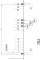
- the period P voltage of the three-phase voltage is 20 ms as shown in figure 5
- this second is divided into 50 periods noted P1, P2, .., P50.
- P1, P2, .., P50 the different tasks are distributed and the different steps of the calculation method are carried out.
- the first five periods P1, P2, P3, P4, P5 correspond to the sampling of the current and the realization of the compression which will be presented later.
- the second module 62A has the order number one and transmits the message M2A in period 31
- the second module 62B has the order number two and transmits the message M2B in period 32 and so on knowing that these order numbers range for example from 1 to 16, the transformer station 10 comprising for example a maximum of 16 feeders.
- the transformer station 10 comprises three second modules 62A, 62B, 62C, and the order number is therefore between 1 and 3.
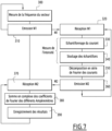
- the first module 60 transmits the first message M1 to each of the second modules 62A, 62B, 62C, via the radio antenna 72.
- This first message M1 is a synchronization message for each current sensor 83A, 83B, 83C.
- the first message M1 is preferably transmitted periodically.
- the transmission period R transmission is predetermined, and preferably equal to one second. In other words, the first message M1 is transmitted every second as visible to the figure 5 .
- the first message M1 contains a synchronization pulse of the current sensors 83A, 83B, 83C. More precisely, for example, the first message M1 comprises a header field, also called a preamble, an SFD (Start of Frame Delimiter) field, a PHR (Physical Header) field, a data field and a CRC (Cyclic Redundancy Check) field.
- the preamble has a size of 4 bytes
- the SFD and PHR fields each have a size of one byte
- the data field is of variable size, denoted n bytes
- the CRC field has a size of 2 bytes.
- the first message M1 consists of the header field, the SFD field, the PHR field, the data field and the CRC field.
- the reception of the SFD by the modules 62A, 62B and 62C constitutes the synchronization pulse ( Figure 4 ).
- the first module 60 measures the first, second and third voltages V1, V2, V3 using the measuring device 66 and the data field of the first message M1 further contains the values of the complex voltages V1, V2, V3.
- the first module 60 After sending the first message M1, the first module 60 waits a predetermined time before sending a first message M1 again.
- each second module 62A, 62B, 62C waits for the synchronization signal from the first message
- each second module 62A, 62B, 62C periodically opens windows for receiving the first message M1 until it receives the first message M1.
- the second module 62A, 62B, 62C will open a window for listening for a few milliseconds for the next first message M1 a little less than a second after receipt of this first message M1.
- the second module 62A, 62B, 62C again opens a window for receiving the first message M1 a second later.
- the second module 62A, 62B, 62C detects the time Tr of reception of the SFD field, the reception of the SFD field causing the triggering of an interruption by the radio receiver of each second module 62A, 62B, 62C, immediately after the demodulation of the SFD.
- the detection of the time of reception Tr then makes it possible to calculate, if necessary, the time Te at which the first message M1 was transmitted by the radio transmitter of the first module 60.
- the time of transmission Te is in fact equal to the time of reception Tr minus a duration Dp of propagation of the first message M1 via the radio link between the first module 60 and the second modules 62A, 62B, 62C, the propagation duration Dp being fixed and known for a predetermined size of the data field of the first message M1.
- each second module 62A, 62B, 62C measures almost simultaneously, with a synchronization error margin preferably less than 10 ⁇ s, more preferably equal to 1 ⁇ s, during a step 220, and via its current sensors 83A, 83B, 83C of its analog-digital converters 90A, 90B, 90C and its microcontroller 84A, 84B, 84C, the three currents IA1, IA2, IA3, IB1, IB2, IB3, IC1, IC2, IC3 of the three phases, and samples the measured values.
- the samples are stored by the microcontroller 84A.
- each second module 62A, 62B, 62C calculates respectively, using the corresponding microcontroller 84A, 84B, 84C, and periodically the active energy EA1, EA2, EA3, EB1, EB2, EB3, EC1, EC2, EC3 for each of the three phases from the values of the voltages V1, V2, V3 measured and received from the primary module 60 via the first message M1 and the values of the intensities IA1, IA2, IA3, IB1, IB2, IB3, IC1, IC2, IC3 measured by the current sensor 83A, 83B, 83C.
- the calculation period of the active energies EA1, EA2, EA3 is equal to the period P voltage , i.e.
- each second module 62A, 62B, 62C is able to calculate respectively the instantaneous electrical powers QA1, QA2, QA3, QB1, QB2, QB3, QC1, QC2, QC3 of the three phases.
- each second module 62A, 62B, 62C transmits a second message M2A, M2B, M2C which is specific to it according to the ordering described during the presentation of the initialization step.
- the second message M2A, M2B, M2C contains respectively the samples of the measured intensities IA1, IA2, IA3; IB1, IB2, IB3; IC1, IC2, IC3.
- the second message M2A, M2B, M2C contains the corresponding values of electrical energy EA1, EA2, EA3, EB1, EB2, EB3, EC1, EC2, EC3 and of electrical power QA1, QA2, QA3, QB1, QB2, QB3, QC1, QC2, QC3 calculated.
- the third module 63 which is listening to the second messages M2A, M2B, M2C receives these second messages.
- the samples of the intensities IA1, IA2, IA3, IB1, IB2, IB3, IC1, IC2, IC3 contained in the corresponding second messages M2A, M2B, M2C are then recovered.
- step 240 the electrical energy and electrical power values are received and in step 250 the electrical energy and power sums are calculated to determine the energy and power in the primary conductor 34, 36, 38.
- the third module 63 calculates, during step 250, from the samples received, the sum of the intensities of the currents flowing in each secondary conductor 42A, 44A, 46A, 42B, 44B, 46B, 42C, 44C, 46C using the calculation unit 104, in order to obtain the value of the intensity of the current flowing in the primary conductor 34, 36, 38.
- the first module 60 measures the frequency F of the three-phase voltage, i.e. the frequency of the voltages V1, V2, V3 of the primary outgoing conductors 34, 36, 38. This measurement of the frequency F is carried out using the measuring device 66.
- the first module 60 therefore sends, during a step 310 similar to step 200, a first message M1 similar to that described previously, knowing that this message M1 also contains in its data field the frequency F of the three-phase voltage, or alternatively the sampling period P ECH used for sampling the intensities measured by each current sensor 83A, 83B, 83C.
- the inverse of the sampling period P ECH is a multiple of the frequency F.
- the frequency sampling frequency F ECH is, for example, chosen with a value 36 times greater than that of the frequency F.
- the first module 60 waits a predetermined time before restarting the measurement of the frequency F and retransmitting the first message M1, it waits approximately one second.
- the next step 320 of receiving the message M1 is similar to the step 210 described previously.
- the sampling of the intensity over several periods P voltage of the three-phase voltage is carried out synchronously for all the current sensors 83A, 83B, 83C.
- the sampling is carried out over five periods of the three-phase voltage P voltage .
- the value of the sampling frequency F ECH is known, this value having been transmitted in the message M1 or having been calculated from the frequency F of the three-phase voltage transmitted in the first message M1.
- the samples are stored in memory by the microcontroller 84A, 84B, 84C, and then, during a step 350, a compression of the samples is carried out in order to limit the quantity of data transmitted by the second messages M2A, M2B, M2C.
- the compression step 350 will be described for the second module 62A, is identical for each second module 62A, 62B, 62C by replacing the letter A with respectively the letter B, respectively C.
- the microcontroller 84A calculates, for example, a predetermined number K of first complex coefficients Re(IAiHj), Im(IAiHj) of the Fourier series decomposition of the three currents IA1, IA2, IA3 of the three phases, where i is the number equal to 1, 2 or 3 of the phase, and j is between 1 and K.
- the predetermined number K is preferably equal to 5 and corresponds to a predetermined rank of harmonics, that is to say to the number of harmonics considered for the calculations, that is to say again to a calculation precision.
- the coefficients of the Fourier series decomposition are, for example, obtained by correlation operations on the samples of the measured values. More precisely, the real coefficient of the fundamental, also denoted Re(IAiH1), is a correlation, over a duration equal to the period P voltage of the three-phase voltage, between the samples of the signal of the intensity lAi and a cosine of frequency equal to the frequency F of the three-phase voltage, where lAi represents the intensity of phase number i, i being equal to 1, 2 or 3.
- the imaginary coefficient of the fundamental also denoted Im(IAiH1), is a correlation, over a duration equal to the period P voltage , between the samples of the signal of the intensity lAi and a sine of frequency equal to the frequency F.
- the real coefficient of harmonic number j denoted Re(IAiHj), j being between 2 and K, is the correlation, over a duration equal to the period P voltage , between the samples of the signal of intensity lAi and a cosine of frequency equal to j times the frequency F.
- the imaginary coefficient of harmonic number j denoted Im(IAiHj), j being between 2 and K, is the correlation, over a duration equal to the period P voltage , between the samples of the signal of intensity lAi and a sine of frequency equal to j times the frequency F.
- the microcontroller thus calculates the complex coefficients Re(IAiHj), Im(IAiHj), i ranging from 1 to 3 and j from 1 to K, of the Fourier series decompositions of the three intensities IA1, IA2, IA3 for the fundamental and harmonics 2 to K.
- step 350 the values of the real electrical energies EA1, EA2, EA3, EB1, EB2, EB3, EC1, EC2, EC3 and the complex powers QA1, QA2, QA3, QB1, QB2, QB3, QC1, QC2, QC3 according to each of the harmonics are calculated in an identical manner to what was previously described for step 220.
- each second module 62A, 62B, 62C transmits the second message M2A, M2B, M2C.
- the second message M2A, M2B, M2C contains respectively the value of the complex coefficients Re(IAiHj), Im(IAiHj), Re(IBiHj), Im(IBiHj), Re(ICiHj), Im(ICiHj), i ranging from 1 to 3 and j from 1 to K in steps of 1, of the Fourier series decompositions of the three intensities IA1, IA2, IA3; IB1, IB2, IB3; IC1, IC2, IC3 for the fundamental H1 and the harmonics 2 to K, instead of the samples of the measured intensities.
- each second module 62A, 62B, 62C After having transmitted the second messages M2A, M2B, M2C, each second module 62A, 62B, 62C returns to step 320 of receiving the first message M1.
- the third module 63 listens to the second messages M2A, M2B, M2C and receives the second messages M2A, M2B, M2C via its antenna 102. Then the third module 63 records and timestamps using its unit 105 the complex coefficients Re(IAiHj), Im(IAiHj), Re(IBiHj), Im(IBiHj), Re(ICiHj), Im(ICiHj), i ranging from 1 to 3 and j from 1 to K in steps of 1, Fourier series decompositions of the three intensities IA1, IA2, IA3; IB1, IB2, IB3; IC1, IC2, IC3 for the fundamental and harmonics 2 to K.
- the third module 63 is also capable, during step 380, of calculating the modulus of the fundamental of each of the phases of the current of each of the feeders 40A, 40B, 40C, the modulus of the harmonics of each of the phases of the current of each of the feeders 40A, 40B, 40C, the modulus of the fundamental of the neutral current of each of the feeders 40A, 40B, 40C, the modulus of the harmonics of the neutral current of each of the feeders 40A, 40B, 40C, the modulus of the harmonics of the general neutral current.
- step 380 sums of real electrical energies EA1, EA2, EA3, EB1, EB2, EB3, EC1, EC2, EC3 and of complex electrical power QA1, QA2, QA3, QB1, QB2, QB3, QC1, QC2, QC3 are carried out in a manner similar to that presented for the currents.
- the third module 63 records in its unit 105 the results of the various calculations carried out.
- the quantities measured and calculated by the calculation system 20 are then displayed on the screen of the human-machine interface 106 of the third module 63. These quantities are displayed in the form of numerical values and/or in the form of curves.
- the third module 63 starts listening again to the second messages M2A, M2B, M2C.
- the first module 60 measures the frequency F. Then, in a manner similar to what was described for step 310, the first module 60 transmits the first message M1 during a step 410.
- a step 420 the reception of the first message M1 is carried out in a manner analogous to that described for step 320. Then, in steps 430 and 440, the sampling of the current and the storage of the samples is carried out, in a manner analogous to that described in steps 330 and 340 respectively.
- the sampling of the current is carried out in step 430 over several periods P voltage , and more particularly over the first five periods P1, P2, P3, P4, P5.
- the samples are acquired successively over several periods P voltage and according to increasing values of a sampling rank during a given period P voltage , the value of the rank being reset at the end of each period P voltage .
- the value of the rank is increasing as a function of time, that is to say that the first sample of the period P1 has the rank 1 as well as the first sample of the periods P2, P3, P4, P5 then the second sample of the period P1 has the rank 2, as well as the second sample of the periods P2, P3, P4, P5 and so on.
- the sampling frequency F ECH is chosen to be 36 times higher than the frequency F, we will have, for the five periods P1, P2, P3, P4, P5, 36 samples whose ranks increase by 1 in an increasing manner with time, from 1 to 36.
- step 450 an average of the samples having the same value of the sampling rank is carried out over said periods, in order to obtain average samples.
- step 460 the operation is similar to that of step 360, except that each second message M2A, M2B, M2C contains the value of the mean samples instead of the Fourier series decomposition coefficients.
- step 470 the second messages M2A, M2B, M2C are received and the operation of this step is similar to that of step 370, except that the values received are average samples, and not Fourier series decomposition coefficients.
- the calculations of the electrical quantities are carried out using the calculation unit 104 in a step 480, during which the sum is carried out samples measured by the different current sensors 83A, 83B, 83C, in order to calculate the value of the current intensity at the output of the transformer 18.
- step 490 is analogous to step 390 described previously.
- the third module 63 starts listening again to the second messages M2A, M2B, M2C.
- the calculation system 20 and the calculation method according to the invention therefore make it possible to obtain the value of the intensity of the current at the output of the transformer, without using a current sensor at the output of the transformer.
- the first module 60 comprises compression software capable of calculating a predetermined number K of the first coefficients Re_j(Vi), Im_j(Vi) of the Fourier series decomposition of each of the voltages V1, V2, V3 of the three phases, where i is the number equal to 1, 2 or 3 of the phase, and j is between 1 and K.
- the predetermined number K is preferably equal to 5.
- the coefficients of the Fourier series decomposition are, for example, obtained by correlation operations on the samples of the measured values as explained above in the case of the currents.
- module 63 uses the data sent by message M1 and which relate to voltages V1, V2, V3.
- the data field of the first message M1 contains the values of the quadratic means, also noted RMS (from the English Roof Mean Square), of each of the three voltages V1, V2, V3.
- the calculation system 20 comprises a calculator, not shown, capable of transmitting, during a step 600, to the first module 60, a request for acquisition of the second messages M2A, M2B, M2C.
- the first module 60 receives this request during a step 610 and sends by through the data field of the first message M1 the request to each second module 62A, 62B, 62C.
- each second module 62A, 62B, 62C the reception of the first message M1 and the measurement of the current are carried out by each second module 62A, 62B, 62C in a manner similar to what was described in steps 210 and 220.
- each second module 62A, 62B, 62C prepares a second message M2A, M2B, M2C and transmits it in a manner similar to what was described for step 230.
- the measured and calculated quantities, transmitted via the second messages M2A, M2B, M2C to the third module 63, are received and stored in a results table and transmitted to the calculator during a step 640.
- the calculator performs during a step 650 calculation operations, such as sums of intensities, sums of powers or sums of energies, as described previously for step 250.
- the calculator is capable of performing centralized management of the measured and calculated quantities.
- the calculator returns if necessary to step 600, in order to request a new acquisition of the quantities measured by the second modules.
- each second message M2A, M2B, M2C contains the identifier of the second module 62A, 62B, 62C which sends it.
- the first module 60 requests, via the first message M1, the sending of the second messages M2A, M2B, M2C.
- the first message M1 then contains a specific request field and the measured intensities and/or the calculated values are sent via the second messages M2A, M2B, M2C to the third module 63 only when this specific field is present in the first message M1.
- the number of radio messages is greatly reduced, which limits the risks of interference on other applications and makes it possible to optimize the energy of the second modules 62A, 62B, 62C.
- the calculation system 20 makes it possible to carry out synchronized measurements of the currents flowing in each feeder, and it is thus possible to sum the measured values or the quantities calculated from these intensity values such as the energy or the instantaneous power.
- All of the modules 60, 62A, ..., 62C, 63 are connected to each other by radio links via their respective radio transmitters and/or receivers 70, 88A, ..., 88C, 102, which makes it easier to install the calculation system 20 in the transformer station 10.
- Compression of the data relating to the measured voltages and currents makes it possible to limit the quantity of data transmitted via the radio links, and thus to limit the own energy consumption of the computing system 20. Furthermore, compression of the data makes it possible to reduce the sensitivity of the computing system 20 to radio disturbances such as jamming or electromagnetic compatibility disturbance, also called EMC disturbance.
- radio disturbances such as jamming or electromagnetic compatibility disturbance, also called EMC disturbance.
- the ordering of the second modules makes it possible to reduce radio interference between the secondary modules 62A, ..., 62C.
- the first module 60 and the third module 63 form only one module carrying out the transmission of the first messages M1, the reception of the second messages M2A, M2B, M2C and the calculations of the electrical quantities. This then makes it possible to reduce the cost of the calculation system 20.
- the electrical network 12 is a three-phase network
- the current measured via the calculation system 20 is a three-phase current.
- the invention also applies to a single-phase electrical network and to the measurement of a single-phase alternating current.
- calculation system 20 according to the invention is less complex and less expensive.
- the second message M2A additionally contains the average IArms1, lArms2, IArms3 of the values of the quadratic averages of the currents IA1, IA2, IA3.
- the calculation system 20 comprises N second modules which are all, with the exception of a second module, associated with one of the N feeders, the last second module being associated with the transformer output.
- This calculation system makes it possible to determine the intensity, power or energy in the feeder which is difficult to access and which is not not associated with a second module. In other operations, certain sums are then replaced by difference calculations.
Landscapes
- Engineering & Computer Science (AREA)
- Power Engineering (AREA)
- Physics & Mathematics (AREA)
- General Physics & Mathematics (AREA)
- Remote Monitoring And Control Of Power-Distribution Networks (AREA)
- Testing Relating To Insulation (AREA)
- Measurement Of Current Or Voltage (AREA)
Claims (15)
- System (20) zum Berechnen einer elektrischen Größe in Bezug auf eine elektrische Installation (10), umfassend einen primären elektrischen Leiter (34, 36, 38, 39) und mehrere sekundäre elektrische Leiter (42A, 44A, 46A, 48A,...42N, 44N, 46N, 48N), die elektrisch mit dem primären elektrischen Leiter (34, 36, 38, 39) verbunden sind, das Berechnungssystem (20) umfassend:- ein erstes Modul (60), umfassend einen Funksender (70),- eine Vielzahl von zweiten Modulen (62A, 62B, 62C), jeweils umfassend einen Funksendeempfänger (86A, 86B, 86C) und einen Stromsensor (83A, 83B, 83C), der geeignet ist, um die Stärke eines Stroms zu messen, der in mindestens einem entsprechenden Leiter von den primären und sekundären elektrischen Leitern fließt,das erste Modul (60) umfassend erste Sendeeinrichtungen (70, 72, 74), um an jedes zweite Modul (62A, 62B, 62C) eine erste Nachricht (M1) zur Zeitsynchronisation zu senden,wobei jedes zweite Modul (62A, 62B, 62C) geeignet ist, um nach Empfang der ersten Nachricht mindestens einen Intensitätswert mittels seines Stromsensors zu messen, und erste Empfangseinrichtungen (84A, 86A, 88A; 84B, 86B, 88B; 84C, 86C, 88C) der ersten Nachricht und zweite Sendeeinrichtungen (84A, 88A; 84B, 88B; 84C, 88C) an ein drittes Modul (63), einer zweiten Nachricht (M2A, M2B, M2C), die den mindestens einen Wert der Intensität (IA1, IA2, IA3; IB1, IB2, IB3; IC1, IC2, IC3) enthält, die von dem entsprechenden Stromsensor (83A, 83B, 83C) nach Empfang der ersten Nachricht gemessen wird, wobei die Stromwerte (IA1, IA2, IA3; IB1, IB2, IB3; IC1, IC2, IC3) von den verschiedenen Stromsensoren (83A, 83B, 83C) quasi-simultan gemessen werden, d. h. mit einer Synchronisationsfehlerspanne von weniger als 10 µs, unddas Rechensystem (20) das dritte Modul (63) umfasst, und das dritte Modul (63) einen Funkempfänger (101) und zweite Empfangseinrichtungen (102, 104) zum Empfangen der zweiten Nachrichten (M2A, M2B, M2C) umfasst,das dritte Modul (63) ferner umfassend ein Element (104) zum Berechnen der elektrischen Größe anhand der Intensitätswerte (IA1, IA2, IA3, IB1, IB2, IB3, IC1, IC2, IC3), die quasi-simultan gemessen und über die zweiten Nachrichten (M2A, M2B, M2C) empfangen werden,dadurch gekennzeichnet, dass jedes zweite Modul (62A, 62B, 62C) geeignet ist, um die entsprechende zweite Nachricht (M2A, M2B, M2C) mit einer vorbestimmten Reihenfolge des Sendens der zweiten Nachrichten (M2A, M2B, M2C) an das dritte Modul (63) zu übertragen, gemäß einer unterschiedlichen Ordnungsnummer, die jedem zweiten Modul (62A, 62B, 62C) zugeordnet ist, wobei jedes zweite Modul (62A, 62B, 62C) während eines Initialisierungsschritts von dem ersten Modul (60) eine dritte Nachricht (M3) empfängt, die für jedes zweite Modul (62A, 62B, 62C) spezifisch ist und die Ordnungsnummer enthält.
- System nach Anspruch 1, dadurch gekennzeichnet, dass das Rechenelement (104) geeignet ist, um eine Summe der Intensitätswerte (IA1, IA2, IA3, IB1, IB2, IB3, IC1, IC2, IC3) zu berechnen, die über die zweiten Nachrichten (M2A, M2B, M2C) empfangen werden.
- System nach einem der vorherigen Ansprüche, dadurch gekennzeichnet, dass das erste Modul (60) ferner ein Element (66) zum Messen der Spannung (V1, V2, V3) umfasst, die in einem entsprechenden Leiter von den primären (34, 36, 38, 39) und sekundären elektrischen Leitern (42A, 44A, 46A, 48A,...42N, 44N, 46N, 48N) fließt, und geeignet ist, um den Wert der gemessenen Spannung (V1, V2, V3) über die erste Nachricht (M1) an die zweiten Module (62A, 62B, 62C) zu übertragen,dass jedes zweite Modul (62A, 62B, 62C) Berechnungseinrichtungen (84A, 84B, 84C) einer momentanen Leistung (QA1, QA2, QA3, QB1, QB2, QB3, QC1, QC2, QC3) anhand des Werts der Spannung (V1, V2, V3), die über die erste Nachricht (M1) empfangen wird, und des Stromwerts (IA1, IA2, IA3; IB1, IB2, IB3; IC1, IC2, IC3), die von dem Stromsensor (83A, 83B, 83C) gemessen wird, umfasst und geeignet ist, um den Wert der elektrischen Leistung (QA1, QA2, QA3, QB1, QB2, QB3, QC1, QC2, QC3) über die zweite Nachricht (M2A, M2B, M2C) an das dritte Modul (63) zu übertragen, unddass das Rechenelement (104) des dritten Moduls (63) geeignet ist, um eine Summe der empfangenen Leistungswerte (QA1, QA2, QA3, QB1, QB2, QB3, QC1, QC2, QC3) zu berechnen.
- System nach Anspruch 1, dadurch gekennzeichnet, dass das erste Modul (60) ferner ein Messelement der Spannung (V1, V2, V3) umfasst, die in einem entsprechenden Leiter von den primären (34, 36, 38, 39) und sekundären elektrischen Leitern (42A, 44A, 46A, 48A,...42N, 44N, 46N, 48N) fließt, und geeignet ist, um den Wert der gemessenen Spannung (V1, V2, V3) über die erste Nachricht (M1) an die zweiten Module (62A, 62B, 62C) zu übertragen,dass jedes zweite Modul (62A, 62B, 62C) Berechnungseinrichtungen (84A, 84B, 84C) einer elektrischen Energie (EA1, EA2, EA3, EB1, EB2, EB3, EC1, EC2, EC3) anhand des Werts der über die erste Nachricht (M1) empfangenen Spannung (V1, V2, V3) und des Werts der Stromstärke (IA1, IA2, IA3, IB1, IB2, IB3, IC1, IC2, IC3), die von dem Stromsensor (83A, 83B, 83C) gemessen wird, und geeignet ist, den Wert der berechneten Energie (EA1, EA2, EA3, EB1, EB2, EB3, EC1, EC2, EC3) über die zweiten Nachrichten (M2A, M2B, M2C) an das dritte Modul (63) zu übertragen, unddass das Berechnungselement (104) des dritten Moduls (63) geeignet ist, um eine Summe der empfangenen Energiewerte (EA1, EA2, EA3, EB1, EB2, EB3, EC1, EC2, EC3) zu berechnen.
- System nach einem der vorherigen Ansprüche, dadurch gekennzeichnet, dass jeder Stromsensor (83A, 83B, 83C) geeignet ist, um die Intensität (IA1, IA2, IA3, IB1, IB2, IB3, IC1, IC2, IC3) des entsprechenden Stroms zu messen, und jedes zweite Modul (62A, 62B, 62C) ein Abtastelement (90A, 90B, 90C) umfasst, das geeignet ist, um die gemessene Intensität gemäß einer Abtastfrequenz (FECH) abzutasten.
- System nach Anspruch 5, dadurch gekennzeichnet, dass die erste Nachricht (M1) den Wert der genannten Abtastfrequenz (FECH) enthält, wobei der Wert vorzugsweise ein vorbestimmter Wert oder ein Vielfaches des Werts der Frequenz (F) der Spannung (V1, V2, V3) von mindestens einem von den primären (34, 36, 38, 39) und sekundären elektrischen Leitern (42A, 44A, 46A, 48A,...42N, 44N, 46N, 48N) ist.
- System nach einem der vorherigen Ansprüche, dadurch gekennzeichnet, dass die zweiten Module (62A, 62B, 62C) erste Komprimierungseinrichtungen (84A, 84B, 84C) umfassen, die geeignet sind, um Koeffizienten der Fourier-Reihenzerlegung des Stromwerts (IA1, IA2, IA3, IB1, IB2, IB3, IC1, IC2, IC3) zu berechnen, der von dem entsprechenden Stromsensor (83A, 83B, 83C) gemessen wird.
- System nach Anspruch 5 oder 6, dadurch gekennzeichnet, dass die Abtastwerte nacheinander über mehrere Perioden (PSpannung) der genannten Spannung (V1, V2, V3) und gemäß ansteigenden Werten eines Abtastrangs während einer gegebenen Periode (PSpannung) erfasst werden, wobei der Wert des Rangs am Ende jeder Periode (PSpannung) zurückgesetzt wird, und dass die zweiten Module (62A, 62B, 62C) erste Komprimierungseinrichtungen (84A, 84B, 84C) der Stromwerte (IA1, IA2, IA3, IB1, IB2, IB3, IC1, IC2, IC3) umfassen, die von dem entsprechenden Stromsensor (83A, 83B, 83C) gemessen werden, wobei diese Komprimierungseinrichtungen (84A, 84B, 84C) den Mittelwert der Abtastungen mit demselben Rangwert berechnen.
- System nach einem der vorherigen Ansprüche, dadurch gekennzeichnet, dass die erste Nachricht (M1) eine Anfrage zur Anforderung des Empfangs der von den zweiten Modulen (62A, 62B, 62C) gemessenen Intensitätswerte enthält.
- Station (10) zum Umwandeln eines elektrischen Stroms, der eine erste Wechselspannung aufweist, in einen elektrischen Strom der eine zweite Wechselspannung aufweist, umfassend:- eine erste Tafel (14), umfassend mindestens einen ankommenden elektrischen Leiter (24A, 26A, 28A, 24B, 26B, 28B), der geeignet ist, um mit einem Stromnetz (12) verbunden zu werden,- eine zweite Schalttafel (16), umfassend mindestens einen primären elektrischen Abgangsleiter (34, 36, 38, 39) und mehrere sekundäre elektrische Abgangsleiter (42A, 44A, 46A, 48A,...42N, 44N, 46N, 48N), wobei jeder sekundäre Abgangsleiter (42A, 44A, 46A, 48A,...42N, 44N, 46N, 48N) elektrisch mit einem entsprechenden primären Abgangsleiter (34, 36, 38, 39) verbunden ist,- einen elektrischen Transformator (18), der zwischen der ersten Tafel (14) und der zweiten Tafel (16) verbunden ist und geeignet ist, um den Strom, der die erste Wechselspannung aufweist in den Strom umzuwandeln, der die zweite Wechselspannung aufweist, und- ein System (20) zum Berechnen einer elektrischen Größe in Bezug auf die zweite Tabelle (16),dadurch gekennzeichnet, dass das Berechnungssystem (20) gemäß einem der vorherigen Ansprüche ist.
- Verfahren zum Berechnen einer elektrischen Größe in Bezug auf eine elektrische Anlage (10), die elektrische Anlage (10) umfassend einen primären elektrischen Leiter (34, 36, 38, 39) und mehrere sekundäre elektrische Leiter (42A, 44A, 46A, 48A,...42N, 44N, 46N, 48N), die elektrisch mit dem primären elektrischen Leiter verbunden sind, wobei das Verfahren mittels eines Berechnungssystems (20) durchgeführt wird, umfassend:- ein erstes Modul (60), umfassend einen Funksender (70),- eine Vielzahl von zweiten Modulen (62A, 62B, 62C), jeweils umfassend einen Funksendeempfänger (86A, 86B, 86C) und einen Stromsensor (83A, 83B, 83C), der geeignet ist, um die Stärke eines Stroms (IA1, IA2, IA3, IB1, IB2, IB3, IC1, IC2, IC3) zu messen, der in einem entsprechenden Leiter von den primären (34, 36, 38) und sekundären elektrischen Leitern (42A, 44A, 46A, 48A,...42N, 44N, 46N, 48N) fließt,das Verfahren umfassend die folgenden Schritte:a) Senden (200, 310, 410), durch das erste Modul (60) und an jedes zweite Modul (62A, 62B, 62C), einer ersten Nachricht (M1) zur zeitlichen Synchronisierung der Messung der Intensität (IA1 IC3) des Stroms, der in den primären (34, 36, 38) oder sekundären Leitern (42A, ..., 46N) fließt,b) Empfangen (210, 320, 420) der ersten Nachricht (M1) durch jedes zweite Modul,c) quasi-simultanes Messen (220), vorzugsweise mit einer Synchronisationsfehlermarge von weniger als 10 µs, der Intensität (IA1, ..., IC3) des Stroms, der in den entsprechenden primären (34, 36, 38) oder sekundären Leitern (42A, ..., 46N) fließt, durch jeden Stromsensor nach Empfangen der ersten Nachricht,das Verfahren ferner umfassend die folgenden Schritte:d) Senden (220, 460, 560) von jedem zweiten Modul (62A, 62B, 62C) und an ein drittes Modul (63) einer zweiten Nachricht (M2A, M2B, M2C), die mindestens einen Wert des Stroms (IA1, ..., IC3) enthält, der von dem entsprechenden Stromsensor (83A, 83B, 83C) gemessen wird,e) Empfangen (240, 470, 370) der zweiten Nachrichten (M2A, M2B, M2C) durch das dritte Modul (63),f) Berechnen (250, 380, 480) der elektrischen Größe aus den Stromwerten (IA1, ..., IC3), die quasi-simultan gemessen und über die zweiten Nachrichten empfangen werden, d. h. mit einer Synchronisationsfehlermarge von weniger als 10 µs,und dadurch gekennzeichnet, dass jedes zweite Modul (62A, 62B, 62C) die entsprechende zweite Nachricht (M2A, M2B, M2C) mit einer vorbestimmten Reihenfolge des Sendens der zweiten Nachrichten (M2A, M2B, M2C) an das dritte Modul (63) überträgt, gemäß einer unterschiedlichen Ordnungsnummer, die jedem zweiten Modul (62A, 62B, 62C) zugeordnet ist, wobei jedes zweite Modul (62A, 62B, 62C) während eines Initialisierungsschritts von dem ersten Modul (60) eine dritte Nachricht (M3) empfängt, die für jedes zweite Modul (62A, 62B, 62C) spezifisch ist und die Ordnungsnummer enthält.
- Verfahren nach Anspruch 11, dadurch gekennzeichnet, dass:- in Schritt a) die Spannung (V1, V2, V3) eines entsprechenden Leiters von den primären (34, 36, 38) und sekundären elektrischen Leitern (42A, ..., 48N) gemessen wird, und die erste Nachricht (M1) den Wert dieser gemessenen Spannung enthält,- in Schritt c) eine elektrische Leistung (QA1, QA2, QA3, QB1, QB2, QB3, QC1, QC2, QC3) und/oder eine Energie (EA1, EA2, EA3, EB1, EB2, EB3, EC1, EC2, EC3) durch das zweite Modul (62A, 62B, 62C) anhand des in Schritt a) gemessenen Werts der Spannung (V1, V2, V3) und des Werts der Stromstärke (IA1, ... IC3), die von dem Stromsensor (83A, 83B, 83C) gemessen wird, berechnet wird,- in Schritt d) die zweite Nachricht (M2) ferner den Wert der berechneten elektrischen Leistung (QA1, QC3) und/oder der berechneten Energie (EA1, EC3) enthält,- in Schritt e) zusätzlich eine Summe der empfangenen Leistungs- oder Energiewerte durch das dritte Modul (63) berechnet wird.
- Verfahren nach Anspruch 11 oder 12, dadurch gekennzeichnet, dass- bei der Messung in Schritt c) die gemessene Intensität (IA1, ..., IC3) mit einer Abtastfrequenz (FECH) abgetastet wird und die gemessenen Intensitäten in Fourier-Reihen zerlegt werden,- bei der Berechnung in Schritt e) die elektrische Größe aus den in Schritt c) erhaltenen Werten der komplexen Fourier-Koeffizienten bis zu einem vorbestimmten Rang von Oberschwingungen berechnet wird.
- Verfahren nach Anspruch 11 oder 12, dadurch gekennzeichnet, dass- bei der Messung in Schritt c) die gemessene Intensität gemäß einer Abtastfrequenz (FECH) abgetastet wird, die Abtastungen nacheinander über mehrere Perioden (PSpannung) der Spannung (V1, V2, V3) eines entsprechenden der primären (34, 36, 38) und sekundären elektrischen Leiter (42A, ...., 48N) und gemäß ansteigenden Werten eines Abtastrangs während einer gegebenen Periode (PSpannung) erfasst werden, wobei der Wert des Rangs am Ende jeder Periode (PSpannung) zurückgesetzt wird, und ein Mittelwert der Abtastungen mit demselben Rangwert gebildet wird,- bei der Berechnung in Schritt e) die elektrische Größe aus den in Schritt c) erlangten Durchschnittswerten der Proben berechnet wird.
- Verfahren nach einem der Ansprüche 12 bis 14, dadurch gekennzeichnet, dass in Schritt a) die erste Nachricht (M1) ferner eine Anfrage zur Anforderung eines Empfangs von Stromstärkenwerten (IA1, IA2, IA3, IB1, IB2, IB3, IC1, IC2, IC3) und/oder elektrischen Leistungen (QA1, QA2, QA3, QB1, QB2, QB3, QC1, QC2, QC3) und/oder Energien (EA1, EA2, EA3, EB1, EB2, EB3, EC1, EC2, EC3), die von den zweiten Modulen (62A, 62B, 62C) gemessen oder berechnet wurden, enthält.
Applications Claiming Priority (1)
| Application Number | Priority Date | Filing Date | Title |
|---|---|---|---|
| FR1355657A FR3007143B1 (fr) | 2013-06-17 | 2013-06-17 | Systeme de calcul d'une grandeur electrique, poste de transformation comprenant un tel systeme et procede de calcul d'une grandeur electrique avec un tel systeme |
Publications (3)
| Publication Number | Publication Date |
|---|---|
| EP2816360A1 EP2816360A1 (de) | 2014-12-24 |
| EP2816360B1 true EP2816360B1 (de) | 2024-11-27 |
| EP2816360C0 EP2816360C0 (de) | 2024-11-27 |
Family
ID=49753258
Family Applications (1)
| Application Number | Title | Priority Date | Filing Date |
|---|---|---|---|
| EP14172570.5A Active EP2816360B1 (de) | 2013-06-17 | 2014-06-16 | Berechnungsverfahren einer elektrischen Messgröße, Transformatoreinheit, die ein solches System umfasst, und Berechnungsverfahren einer elektrischen Messgröße mit einem solchen System |
Country Status (10)
| Country | Link |
|---|---|
| US (1) | US10254126B2 (de) |
| EP (1) | EP2816360B1 (de) |
| KR (1) | KR102237335B1 (de) |
| CN (2) | CN104237627A (de) |
| AU (1) | AU2014203254B2 (de) |
| BR (1) | BR102014014650B1 (de) |
| CA (1) | CA2854090C (de) |
| FR (1) | FR3007143B1 (de) |
| RU (1) | RU2652170C2 (de) |
| ZA (1) | ZA201404379B (de) |
Families Citing this family (13)
| Publication number | Priority date | Publication date | Assignee | Title |
|---|---|---|---|---|
| FR3013457B1 (fr) | 2013-11-15 | 2016-01-08 | Schneider Electric Ind Sas | Systeme de calcul de l'energie electrique, armoire electrique comprenant un tel systeme, poste de transformation et procede de calcul associes |
| IL237178A (en) * | 2014-03-09 | 2016-02-29 | Moshe Cohen Gadol | Electromagnetic radiation detection system and method |
| FR3030764B1 (fr) | 2014-12-22 | 2018-03-09 | Schneider Electric Industries Sas | Dispositif et procede de surveillance d'une tension ou d'une intensite, systeme de surveillance d'un tableau electrique, armoire electrique et poste de transformation associes |
| FR3032037B1 (fr) * | 2015-01-22 | 2020-05-01 | Schneider Electric Industries Sas | Dispositif et procede de surveillance d'une tension ou d'une intensite, systeme de surveillance d'un tableau electrique, armoire electrique et poste de transformation associes |
| KR20180135374A (ko) * | 2017-06-12 | 2018-12-20 | 엘지전자 주식회사 | 전류 센싱에 기반한 전력 소비 모니터링 방법, 무선 전력 센싱 장치 및 클라우드 장치 |
| CN107271913B (zh) * | 2017-06-28 | 2019-03-22 | 北京工业大学 | 一种应用于动力电池剩余容量预测的方法 |
| MX2020000895A (es) * | 2017-07-26 | 2020-07-22 | Panoramic Power Ltd | Sincronización temporal de sensores de potencia autoalimentados y un controlador central que recoge muestras de los mismos. |
| CA3026918C (en) * | 2017-12-14 | 2023-08-01 | Veris Industries, Llc | Energy metering for a building |
| CN108152571B (zh) * | 2017-12-29 | 2020-06-30 | 国网浙江省电力公司湖州供电公司 | 一种剩余电流动态跟踪分析记录曲线触发短信装置及方法 |
| CN108964264A (zh) * | 2018-06-22 | 2018-12-07 | 国电南瑞科技股份有限公司 | 智能变电站就地化装置的无线调试实现方法 |
| FR3090885B1 (fr) * | 2018-12-20 | 2021-05-07 | Schneider Electric Ind Sas | Procédé et système de mesure de grandeurs électriques |
| RU2749088C1 (ru) * | 2020-06-26 | 2021-06-04 | Общество с ограниченной ответственностью «Виртуальная реальность плюс» | Способ мониторинга энергопотребления в обособленном участке электрической сети |
| CN113866651B (zh) * | 2021-09-18 | 2022-08-02 | 珠海格力电器股份有限公司 | 遥控器的低电量的检测方法、检测装置和遥控器 |
Family Cites Families (33)
| Publication number | Priority date | Publication date | Assignee | Title |
|---|---|---|---|---|
| US4672555A (en) * | 1984-10-18 | 1987-06-09 | Massachusetts Institute Of Technology | Digital ac monitor |
| US5517106A (en) | 1989-08-07 | 1996-05-14 | Digital Kwh, Inc. | Method and apparatus for digitally measuring electrical power |
| US5325048A (en) * | 1992-04-14 | 1994-06-28 | Digital Kwh Inc. | Method and apparatus for calibrating a digital electric engergy consumption meter |
| US5805395A (en) | 1996-12-13 | 1998-09-08 | Abb Power T&D Company Inc. | Half-cycle summation V/Hz relay for generator and transformer over-excitation protection |
| US5995911A (en) | 1997-02-12 | 1999-11-30 | Power Measurement Ltd. | Digital sensor apparatus and system for protection, control, and management of electricity distribution systems |
| EP1482664A3 (de) * | 2003-05-20 | 2005-04-13 | Yamaha Corporation | Signalübertragungssystem |
| CN1996792A (zh) * | 2006-01-01 | 2007-07-11 | 中兴通讯股份有限公司 | 一种上行参考信号定时同步的方法 |
| CN1901509B (zh) * | 2006-07-26 | 2013-05-29 | 白杰 | 网络节点间同步数据的同步方法 |
| JP5105834B2 (ja) * | 2006-11-17 | 2012-12-26 | キヤノン株式会社 | 制御装置及びその制御方法、通信装置及びその制御方法、通信システム、及び、プログラム |
| US8473250B2 (en) * | 2006-12-06 | 2013-06-25 | Solaredge, Ltd. | Monitoring of distributed power harvesting systems using DC power sources |
| CN100579078C (zh) * | 2007-06-19 | 2010-01-06 | 华为技术有限公司 | 实现上行资源调度的方法、基站和用户终端 |
| WO2009037163A2 (en) | 2007-09-17 | 2009-03-26 | Ably As | Method and apparatus for monitoring power transmission |
| GB2452989A (en) | 2007-09-24 | 2009-03-25 | Hughes Energy Systems Ltd | Multi-circuit electricity metering |
| EP2249453B1 (de) | 2008-01-07 | 2018-04-25 | Panasonic Intellectual Property Management Co., Ltd. | Stromakkumulationsvorrichtung |
| EP2283371B1 (de) | 2008-05-23 | 2012-09-26 | Gloor Engineering | Leistungsmessvorrichtung |
| US8014964B1 (en) | 2008-08-23 | 2011-09-06 | Khalsa Research and Consultancy Pty Ltd | Electrical power and energy measurement method and apparatus |
| AU2010204844B2 (en) * | 2009-01-14 | 2013-01-10 | Accenture Global Services Limited | Distribution system analysis using meter data |
| US8103466B2 (en) | 2009-01-14 | 2012-01-24 | Accenture Global Services Limited | Distribution system analysis using meter data |
| CN102460188B (zh) | 2009-04-16 | 2015-09-16 | 全景电力有限公司 | 用于在断路器点的功率消耗测量的设备和方法 |
| FR2945170B1 (fr) * | 2009-04-30 | 2012-02-24 | Peugeot Citroen Automobiles Sa | Procede pour emettre des messages periodiques |
| US8744787B2 (en) * | 2009-12-24 | 2014-06-03 | Schneider Electric USA, Inc. | Dynamic load estimation of multiple branch circuits |
| FR2956212B1 (fr) * | 2010-02-08 | 2012-03-09 | Schneider Electric Ind Sas | Dispositif et procede de comptage d'energie electrique |
| US9793752B1 (en) * | 2010-06-28 | 2017-10-17 | Amazon Technologies, Inc. | Reserve power system for data center |
| CA3035892C (en) * | 2010-07-02 | 2021-06-29 | Belkin International, Inc. | Systems and methods for measuring electrical power usage in a structure and systems and methods of calibrating the same |
| CN102043115B (zh) | 2010-11-02 | 2013-02-20 | 深圳市双合电气股份有限公司 | 一种电力系统线路参数网络在线带电测量方法 |
| GB2490340B (en) * | 2011-04-27 | 2015-02-18 | Northern Design Electronics Ltd | Improvements in and relating to voltage measurement |
| FR2975779B1 (fr) | 2011-05-24 | 2014-01-17 | Schneider Electric Ind Sas | Capteur de courant sans-fil |
| DE102011107932B3 (de) * | 2011-07-19 | 2013-01-24 | EurA-Consult GmbH | System und Verfahren zur Bestimmung elektrischer Kenngrößen |
| FR2978830B1 (fr) * | 2011-08-04 | 2019-07-26 | Schneider Electric Industries Sas | Systeme de mesure de l'energie electrique, poste de transformation comprenant un tel systeme et procede de mesure de l'energie electrique avec un tel systeme |
| US9081043B2 (en) * | 2012-02-10 | 2015-07-14 | Sharp Laboratories Of America, Inc. | System and method for calculating power using contactless voltage waveform shape sensor |
| CN202649306U (zh) | 2012-06-04 | 2013-01-02 | 珠海派诺科技股份有限公司 | 一种三相电参数测量装置 |
| FR2993366B1 (fr) | 2012-07-10 | 2015-05-15 | Schneider Electric Ind Sas | Systeme de mesure d'au moins une grandeur electrique, poste de transformation electrique comprenant un tel systeme de mesure et procede de mesure associe |
| CN102937675B (zh) | 2012-10-22 | 2015-12-02 | 江苏省电力公司常州供电公司 | 配电网实时数据采集和故障定位系统的工作方法 |
-
2013
- 2013-06-17 FR FR1355657A patent/FR3007143B1/fr not_active Expired - Fee Related
-
2014
- 2014-06-10 CA CA2854090A patent/CA2854090C/fr active Active
- 2014-06-11 US US14/301,517 patent/US10254126B2/en active Active
- 2014-06-13 ZA ZA2014/04379A patent/ZA201404379B/en unknown
- 2014-06-16 KR KR1020140073139A patent/KR102237335B1/ko not_active Expired - Fee Related
- 2014-06-16 AU AU2014203254A patent/AU2014203254B2/en active Active
- 2014-06-16 RU RU2014124391A patent/RU2652170C2/ru active
- 2014-06-16 EP EP14172570.5A patent/EP2816360B1/de active Active
- 2014-06-16 BR BR102014014650-4A patent/BR102014014650B1/pt active IP Right Grant
- 2014-06-17 CN CN201410269769.3A patent/CN104237627A/zh active Pending
- 2014-06-17 CN CN201910292745.2A patent/CN110058079B/zh active Active
Also Published As
| Publication number | Publication date |
|---|---|
| CN110058079A (zh) | 2019-07-26 |
| CN110058079B (zh) | 2023-02-17 |
| AU2014203254A1 (en) | 2015-01-22 |
| EP2816360A1 (de) | 2014-12-24 |
| FR3007143B1 (fr) | 2015-07-17 |
| CA2854090A1 (fr) | 2014-12-17 |
| KR102237335B1 (ko) | 2021-04-06 |
| CN104237627A (zh) | 2014-12-24 |
| RU2652170C2 (ru) | 2018-04-25 |
| US20140368351A1 (en) | 2014-12-18 |
| BR102014014650B1 (pt) | 2021-11-03 |
| BR102014014650A2 (pt) | 2015-06-23 |
| CA2854090C (fr) | 2022-01-11 |
| RU2014124391A (ru) | 2015-12-27 |
| ZA201404379B (en) | 2015-07-29 |
| FR3007143A1 (fr) | 2014-12-19 |
| AU2014203254B2 (en) | 2018-10-25 |
| US10254126B2 (en) | 2019-04-09 |
| KR20140146550A (ko) | 2014-12-26 |
| EP2816360C0 (de) | 2024-11-27 |
Similar Documents
| Publication | Publication Date | Title |
|---|---|---|
| EP2816360B1 (de) | Berechnungsverfahren einer elektrischen Messgröße, Transformatoreinheit, die ein solches System umfasst, und Berechnungsverfahren einer elektrischen Messgröße mit einem solchen System | |
| EP2739982B1 (de) | System zum messen einer elektrischen leistung, transformationseinheit mit solch einem system und verfahren zum messen einer elektrischen leistung mit solch einem system | |
| US20200282856A1 (en) | Automated electric vehicle charging | |
| EP2550509A1 (de) | Verfahren und system zur zeitsynchronisation von signalphasen aus entsprechenden messvorrichtungen | |
| EP2685267B1 (de) | Verfahren und System zum Messen mit Identifizierung der Phasen | |
| FR2991057A1 (fr) | Systeme de mesure de l'energie electrique, poste de transformation comprenant un tel systeme et procede de mesure de l'energie electrique avec un tel systeme | |
| EP2730929A1 (de) | Verfahren und System zur Bestimmung der Primärspannung eines Transformators und Trafostation, die ein solches Bestimmungssystem umfasst | |
| EP2873981B1 (de) | Berechnungssystem der elektrischen Energie, elektrischer Schaltschrank, der ein solches System umfasst, entsprechende Trafostation und entsprechendes Berechnungsverfahren | |
| EP3037832B1 (de) | Verfahren und vorrichtung zur überwachung einer spannung oder einer stromstärke, entsprechendes überwachungssystem einer elektrischen schalttafel, entsprechender schaltschrank und entsprechende transformationseinheit | |
| EP2579611B1 (de) | Verfahren zur lokalisierung von stromentnahmepunkten in einem stromverteilugssystem, entsprechende datenverarbeitungsvorrichtung, entsprechender stromabnehmer und stromzähler | |
| EP3001208B1 (de) | System zum erkennen einer elektrischen störung, und entsprechendes verfahren | |
| EP3048448B1 (de) | Verfahren und vorrichtung zur überwachung einer spannung oder eines stroms, entsprechendes überwachungssystem einer elektrischen schalttafel, entsprechender schaltschrank und entsprechende transformatoreinheit | |
| EP3125403A1 (de) | Überwachungssystem einer umwandlungsstation | |
| FR2987949A1 (fr) | Procede de localisation de points consommateurs de courant dans un systeme de distribution de courant electrique, dispositif de traitement et systeme de distribution de courant electrique associes. | |
| FR3112261A1 (fr) | Procede et dispositif de transmission d’un message |
Legal Events
| Date | Code | Title | Description |
|---|---|---|---|
| PUAI | Public reference made under article 153(3) epc to a published international application that has entered the european phase |
Free format text: ORIGINAL CODE: 0009012 |
|
| 17P | Request for examination filed |
Effective date: 20140616 |
|
| AK | Designated contracting states |
Kind code of ref document: A1 Designated state(s): AL AT BE BG CH CY CZ DE DK EE ES FI FR GB GR HR HU IE IS IT LI LT LU LV MC MK MT NL NO PL PT RO RS SE SI SK SM TR |
|
| AX | Request for extension of the european patent |
Extension state: BA ME |
|
| R17P | Request for examination filed (corrected) |
Effective date: 20150604 |
|
| RBV | Designated contracting states (corrected) |
Designated state(s): AL AT BE BG CH CY CZ DE DK EE ES FI FR GB GR HR HU IE IS IT LI LT LU LV MC MK MT NL NO PL PT RO RS SE SI SK SM TR |
|
| STAA | Information on the status of an ep patent application or granted ep patent |
Free format text: STATUS: EXAMINATION IS IN PROGRESS |
|
| 17Q | First examination report despatched |
Effective date: 20200615 |
|
| GRAP | Despatch of communication of intention to grant a patent |
Free format text: ORIGINAL CODE: EPIDOSNIGR1 |
|
| STAA | Information on the status of an ep patent application or granted ep patent |
Free format text: STATUS: GRANT OF PATENT IS INTENDED |
|
| INTG | Intention to grant announced |
Effective date: 20240417 |
|
| GRAJ | Information related to disapproval of communication of intention to grant by the applicant or resumption of examination proceedings by the epo deleted |
Free format text: ORIGINAL CODE: EPIDOSDIGR1 |
|
| STAA | Information on the status of an ep patent application or granted ep patent |
Free format text: STATUS: EXAMINATION IS IN PROGRESS |
|
| GRAP | Despatch of communication of intention to grant a patent |
Free format text: ORIGINAL CODE: EPIDOSNIGR1 |
|
| STAA | Information on the status of an ep patent application or granted ep patent |
Free format text: STATUS: GRANT OF PATENT IS INTENDED |
|
| INTC | Intention to grant announced (deleted) | ||
| INTG | Intention to grant announced |
Effective date: 20240808 |
|
| GRAS | Grant fee paid |
Free format text: ORIGINAL CODE: EPIDOSNIGR3 |
|
| GRAA | (expected) grant |
Free format text: ORIGINAL CODE: 0009210 |
|
| STAA | Information on the status of an ep patent application or granted ep patent |
Free format text: STATUS: THE PATENT HAS BEEN GRANTED |
|
| AK | Designated contracting states |
Kind code of ref document: B1 Designated state(s): AL AT BE BG CH CY CZ DE DK EE ES FI FR GB GR HR HU IE IS IT LI LT LU LV MC MK MT NL NO PL PT RO RS SE SI SK SM TR |
|
| REG | Reference to a national code |
Ref country code: GB Ref legal event code: FG4D Free format text: NOT ENGLISH |
|
| REG | Reference to a national code |
Ref country code: CH Ref legal event code: EP |
|
| REG | Reference to a national code |
Ref country code: DE Ref legal event code: R096 Ref document number: 602014091223 Country of ref document: DE |
|
| REG | Reference to a national code |
Ref country code: IE Ref legal event code: FG4D Free format text: LANGUAGE OF EP DOCUMENT: FRENCH |
|
| U01 | Request for unitary effect filed |
Effective date: 20241220 |
|
| U07 | Unitary effect registered |
Designated state(s): AT BE BG DE DK EE FI FR IT LT LU LV MT NL PT RO SE SI Effective date: 20250113 |
|
| PG25 | Lapsed in a contracting state [announced via postgrant information from national office to epo] |
Ref country code: HR Free format text: LAPSE BECAUSE OF FAILURE TO SUBMIT A TRANSLATION OF THE DESCRIPTION OR TO PAY THE FEE WITHIN THE PRESCRIBED TIME-LIMIT Effective date: 20241127 Ref country code: IS Free format text: LAPSE BECAUSE OF FAILURE TO SUBMIT A TRANSLATION OF THE DESCRIPTION OR TO PAY THE FEE WITHIN THE PRESCRIBED TIME-LIMIT Effective date: 20250327 |
|
| PG25 | Lapsed in a contracting state [announced via postgrant information from national office to epo] |
Ref country code: ES Free format text: LAPSE BECAUSE OF FAILURE TO SUBMIT A TRANSLATION OF THE DESCRIPTION OR TO PAY THE FEE WITHIN THE PRESCRIBED TIME-LIMIT Effective date: 20241127 |
|
| PG25 | Lapsed in a contracting state [announced via postgrant information from national office to epo] |
Ref country code: NO Free format text: LAPSE BECAUSE OF FAILURE TO SUBMIT A TRANSLATION OF THE DESCRIPTION OR TO PAY THE FEE WITHIN THE PRESCRIBED TIME-LIMIT Effective date: 20250227 |
|
| PG25 | Lapsed in a contracting state [announced via postgrant information from national office to epo] |
Ref country code: GR Free format text: LAPSE BECAUSE OF FAILURE TO SUBMIT A TRANSLATION OF THE DESCRIPTION OR TO PAY THE FEE WITHIN THE PRESCRIBED TIME-LIMIT Effective date: 20250228 |
|
| PG25 | Lapsed in a contracting state [announced via postgrant information from national office to epo] |
Ref country code: PL Free format text: LAPSE BECAUSE OF FAILURE TO SUBMIT A TRANSLATION OF THE DESCRIPTION OR TO PAY THE FEE WITHIN THE PRESCRIBED TIME-LIMIT Effective date: 20241127 |
|
| PG25 | Lapsed in a contracting state [announced via postgrant information from national office to epo] |
Ref country code: RS Free format text: LAPSE BECAUSE OF FAILURE TO SUBMIT A TRANSLATION OF THE DESCRIPTION OR TO PAY THE FEE WITHIN THE PRESCRIBED TIME-LIMIT Effective date: 20250227 |
|
| PG25 | Lapsed in a contracting state [announced via postgrant information from national office to epo] |
Ref country code: SM Free format text: LAPSE BECAUSE OF FAILURE TO SUBMIT A TRANSLATION OF THE DESCRIPTION OR TO PAY THE FEE WITHIN THE PRESCRIBED TIME-LIMIT Effective date: 20241127 |
|
| PGFP | Annual fee paid to national office [announced via postgrant information from national office to epo] |
Ref country code: GB Payment date: 20250617 Year of fee payment: 12 |
|
| PG25 | Lapsed in a contracting state [announced via postgrant information from national office to epo] |
Ref country code: SK Free format text: LAPSE BECAUSE OF FAILURE TO SUBMIT A TRANSLATION OF THE DESCRIPTION OR TO PAY THE FEE WITHIN THE PRESCRIBED TIME-LIMIT Effective date: 20241127 |
|
| PG25 | Lapsed in a contracting state [announced via postgrant information from national office to epo] |
Ref country code: CZ Free format text: LAPSE BECAUSE OF FAILURE TO SUBMIT A TRANSLATION OF THE DESCRIPTION OR TO PAY THE FEE WITHIN THE PRESCRIBED TIME-LIMIT Effective date: 20241127 |
|
| U20 | Renewal fee for the european patent with unitary effect paid |
Year of fee payment: 12 Effective date: 20250624 |
|
| PLBE | No opposition filed within time limit |
Free format text: ORIGINAL CODE: 0009261 |
|
| STAA | Information on the status of an ep patent application or granted ep patent |
Free format text: STATUS: NO OPPOSITION FILED WITHIN TIME LIMIT |
|
| REG | Reference to a national code |
Ref country code: CH Ref legal event code: L10 Free format text: ST27 STATUS EVENT CODE: U-0-0-L10-L00 (AS PROVIDED BY THE NATIONAL OFFICE) Effective date: 20251008 |
|
| 26N | No opposition filed |
Effective date: 20250828 |
|
| REG | Reference to a national code |
Ref country code: CH Ref legal event code: H13 Free format text: ST27 STATUS EVENT CODE: U-0-0-H10-H13 (AS PROVIDED BY THE NATIONAL OFFICE) Effective date: 20260127 |
|
| PG25 | Lapsed in a contracting state [announced via postgrant information from national office to epo] |
Ref country code: MC Free format text: LAPSE BECAUSE OF FAILURE TO SUBMIT A TRANSLATION OF THE DESCRIPTION OR TO PAY THE FEE WITHIN THE PRESCRIBED TIME-LIMIT Effective date: 20241127 |
|
| PG25 | Lapsed in a contracting state [announced via postgrant information from national office to epo] |
Ref country code: IE Free format text: LAPSE BECAUSE OF NON-PAYMENT OF DUE FEES Effective date: 20250616 |
|
| PG25 | Lapsed in a contracting state [announced via postgrant information from national office to epo] |
Ref country code: CH Free format text: LAPSE BECAUSE OF NON-PAYMENT OF DUE FEES Effective date: 20250630 |