EP2730929A1 - Verfahren und System zur Bestimmung der Primärspannung eines Transformators und Trafostation, die ein solches Bestimmungssystem umfasst - Google Patents
Verfahren und System zur Bestimmung der Primärspannung eines Transformators und Trafostation, die ein solches Bestimmungssystem umfasst Download PDFInfo
- Publication number
- EP2730929A1 EP2730929A1 EP13191995.3A EP13191995A EP2730929A1 EP 2730929 A1 EP2730929 A1 EP 2730929A1 EP 13191995 A EP13191995 A EP 13191995A EP 2730929 A1 EP2730929 A1 EP 2730929A1
- Authority
- EP
- European Patent Office
- Prior art keywords
- voltage
- primary
- transformer
- current
- measured
- Prior art date
- Legal status (The legal status is an assumption and is not a legal conclusion. Google has not performed a legal analysis and makes no representation as to the accuracy of the status listed.)
- Granted
Links
Images
Classifications
-
- G—PHYSICS
- G01—MEASURING; TESTING
- G01R—MEASURING ELECTRIC VARIABLES; MEASURING MAGNETIC VARIABLES
- G01R15/00—Details of measuring arrangements of the types provided for in groups G01R17/00 - G01R29/00, G01R33/00 - G01R33/26 or G01R35/00
- G01R15/14—Adaptations providing voltage or current isolation, e.g. for high-voltage or high-current networks
- G01R15/18—Adaptations providing voltage or current isolation, e.g. for high-voltage or high-current networks using inductive devices, e.g. transformers
- G01R15/183—Adaptations providing voltage or current isolation, e.g. for high-voltage or high-current networks using inductive devices, e.g. transformers using transformers with a magnetic core
-
- G—PHYSICS
- G01—MEASURING; TESTING
- G01R—MEASURING ELECTRIC VARIABLES; MEASURING MAGNETIC VARIABLES
- G01R31/00—Arrangements for testing electric properties; Arrangements for locating electric faults; Arrangements for electrical testing characterised by what is being tested not provided for elsewhere
- G01R31/50—Testing of electric apparatus, lines, cables or components for short-circuits, continuity, leakage current or incorrect line connections
- G01R31/62—Testing of transformers
-
- G—PHYSICS
- G01—MEASURING; TESTING
- G01R—MEASURING ELECTRIC VARIABLES; MEASURING MAGNETIC VARIABLES
- G01R31/00—Arrangements for testing electric properties; Arrangements for locating electric faults; Arrangements for electrical testing characterised by what is being tested not provided for elsewhere
- G01R31/50—Testing of electric apparatus, lines, cables or components for short-circuits, continuity, leakage current or incorrect line connections
- G01R31/72—Testing of electric windings
Definitions
- the present invention relates to a method for determining the primary voltage of an electrical transformer, the electrical transformer having a vacuum transformation ratio and comprising a primary winding adapted to present the primary voltage between its ends and to be traversed by a primary current , a secondary winding clean to have a secondary voltage between its ends and to be traversed by a secondary current.
- the invention also relates to a system for determining the primary voltage of an electrical transformer intended to implement such a method.
- the terminal distribution of the public distribution networks of a polyphase current to energy consumers is carried out at low voltage from medium voltage / low voltage substations, also called MV / LV substations.
- Each MV / LV substation is in the form of a radial structure comprising a plurality of low voltage lines, each serving a certain number of consumers.
- Each low voltage line comprises a phase conductor for each phase of the polyphase current delivered and a neutral conductor.
- Each of these MV / LV substations is itself connected to a medium voltage line whose origin is on a high voltage / medium voltage substation, also called HT / MV substation.
- the low voltage is likely to vary depending on the loads connected to the low voltage network and the characteristics of the low voltage lines.
- the conformity of the voltage delivered is checked according to two methods.
- a first method consists, in the design phase of the network, in the calculation of cable sizing and load distribution, in order to guarantee a minimum voltage drop in the conductors compatible with the voltage limits allowed by the loads.
- a second method, feasible in operating condition, is to adjust the voltage on the low voltage lines to adapt to the conditions of the moment.
- This second method also includes adjusting the voltage upstream.
- controllers in charge of HV / MV substations automatically and permanently controlled, make it possible to adjust the voltage at the head end of the network in order to minimize online losses. maintaining an acceptable voltage downstream.
- off-load adjusters of the MV / LV substations make it possible to adjust the voltage upstream.
- These off-load adjusters include manual switches, also known as regulators, located in the distribution transformers. They make it possible to choose the most suitable winding of the transformer according to the structure of the network to which it is connected. Off-load adjusters are operated very occasionally, that is, a few times throughout the life of the transformer, to monitor structural changes in the network and consumers.
- the insertion of a decentralized production in the network locally causes overruns of the maximum voltage.
- the dimensioning of the network calculated during its design, does not take into account the energy flows resulting from decentralized productions. It is then necessary to regularly monitor the current flowing in the primary winding of the transformer, also called primary current, the voltage between the ends of the primary winding, also called primary voltage, the current flowing in the secondary winding of the transformer, also called secondary current, and the voltage between the ends of the secondary winding, also called secondary voltage.
- the object of the invention is therefore to provide a method for determining the primary voltage of a more precise transformer, while being of limited cost and compatible with the existing fleet of MV / LV substations.
- the invention also relates to a system for determining the primary voltage of an electrical transformer, the electrical transformer having a vacuum transformation ratio and comprising a primary winding adapted to present the primary voltage between its ends and to be traversed by a primary current, a secondary winding clean to have a secondary voltage between its ends and to be crossed by a secondary current.
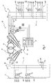
- a transformer station 10 connected to an alternating electrical network 12 comprises a first panel 14, a second panel 16, an electrical transformer 18 provided with a regulator 20 and connected between the first panel and the second panel, as well as a system 22 for determining a primary voltage U1j of the transformer 18.
- the transformer station 10 is adapted to transform the electric current I1j delivered by the network 12 and having a first alternating voltage U1j, into an electric current I2j having a second alternating voltage U2j.
- the electrical network 12 is an alternating network comprising P phases, P being an integer greater than or equal to 1, such as a three-phase network. In other words, in the embodiment described in figure 1 , P is equal to 3
- the voltages U1j, U2j and currents I1j, I2j of each phase conductor are U1a, U1b, U1c, U2a, U2b, U2c and I1a, I1b, I1c, I2a, I2b, I2c.
- the electrical network 12 is a medium voltage network, that is to say a network whose voltage is greater than 1000 V and less than 50 000 V.
- the first three-phase voltage U1j is then a medium voltage.
- the first array 14 includes several arrivals 24A, 24B, each arrival 24A, 24B having a first 26A, 26B, a second 28A, 28B and a third 30A, 30B incoming conductor.
- Each incoming conductor 26A, 26B, 28A, 28B, 30A, 30B is connected to the electrical network 12 via, for example, a respective incoming circuit breaker 31.
- the three-phase current I1j flowing in the corresponding incoming conductors 26A, 26B, 28A, 28B, 30A, 30B has the first three-phase voltage U1j.
- the first incoming conductors 26A, 26B, the second incoming conductors 28A, 28B, the third incoming conductors 30A, 30B are respectively connected to a first primary connecting conductor 32, a second primary connecting conductor 33 and a third primary connecting conductor 34. These primary connecting conductors connect the inlets 24 to the regulator 20 of the transformer 18.
- the second array 16 comprises a first 35, a second 36, a third 37, and a fourth 38 secondary connecting conductors and a plurality N of 40A, 40B, ..., 40N, namely a first start 40A, a second departure 40B, ..., a Nth departure 40N, each 40A, 40B, ..., 40N being adapted to deliver a three-phase voltage U2j.
- the secondary connecting conductors 35, 36, 37, 38 connect the transformer 18 to the outlets 40A, ..., 40N.
- Each start 40A, ..., 40N is a low voltage start U2j, that is to say a start whose voltage is less than 1000 Volts.
- the second three-phase voltage U2j is then a low voltage.
- the first start 40A comprises a first 42A, a second 44A, a third 46A and a fourth 48A starting conductors and three starting circuit breakers 50.
- the first, second, third starting conductors 42A, 42B, 42C are respectively connected to the first, second and third secondary connecting conductors 35, 36, 37 via a corresponding starter circuit breaker 50.
- the fourth starting conductor 48A is directly connected to the fourth secondary connecting conductor 38.
- the secondary connecting conductors 35, 36, 37 and the corresponding output conductors 42A, 44A, 46A have the same voltage U2j, each corresponding to a respective phase U2a, U2b, U2c of the second three-phase voltage.
- the other 40B, ..., 40N are identical to the first 40A departure described above, and have the same elements each time replacing the letter A by the corresponding letter B, ..., N concerning the references of the elements.
- the electrical transformer 18 is able to transform the current I1j from the electrical network having the first alternating voltage U1j into the current I2j delivered to the second array 16 and having the second alternating voltage U2j.
- the electrical transformer 18 comprises a primary winding 52 connected to the first array 14 and a secondary winding 54 connected to the second array 16, each winding 52, 54 comprising an electromagnetic coil, not shown, for each phase a, b, c of the corresponding alternating current. .
- the clean current to flow in the primary winding 52 of the transformer is called primary current and is noted I1j, j being the index of the corresponding phase, equal to a, b or c.
- the voltage between the ends of the primary winding 52 is called the primary voltage and is noted U1j for each phase j of the corresponding alternating current.
- the current adapted to flow in the secondary winding 54 of the transformer is called the secondary current I2j, and the voltage between the ends of the secondary winding 54 is called secondary voltage U2j for each phase j of the corresponding alternating current, j being equal to , goat.
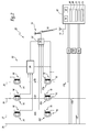
- the determination system 22 visible on the figure 1 and part of which is visible on a larger scale on the figure 2 , comprises sensors 56A, 56B, 56C of the primary current, sensors 58A, 58B, 58C of the secondary current, sensors 59A, 59B, 59C of the secondary voltage, as well as an information processing unit 60.
- the determination system 22 is able to measure, using the primary current sensors 56A, 56B, 56C, the primary currents I1a, I1b, I1c passing through each of the three primary connecting conductors 32, 33, 34 connected to the primary winding 52 of the transformer.
- the determination system 22 is able to measure, using the secondary current sensors 58A, 58B, 58C, the secondary currents I2a, I2b, 12c passing through each of the three secondary connecting conductors 35, 36, 37 connected to the secondary winding 54 of the transformer.
- the determination system 22 is able to measure, by means of the voltage sensors 59A, 59B, 59C, the secondary voltages U2a, U2b, U2c, relative to the neutral conductor 38, of each of the three secondary connecting conductors 35. , 36, 37 connected to the secondary winding 54.
- the information processing unit 60 comprises a processor 62 and a memory 64 associated with the processor 62.
- the memory 64 is able to store a first software 66 for calculating the voltage drop. ⁇ U U at the terminals of the transformer on the side of the secondary winding 54, a second software 68 for calculating the primary voltage module U1a, U1b, U1c of the transformer and a third software 70 for calculating the phase shift of the primary voltage U1a, U1b, U1c with the primary current I1a, I1b, I1c.
- the information processing unit 60 comprises a communication software 72 able to communicate with the current sensors 56A,..., 58C.
- the processing unit includes software 73 for acquiring values measured by the primary current sensors 56A, 56B, 56C, the secondary current sensors 58A, 58B, 58C and the secondary voltage sensors 59A, 59B, 59C.
- the second calculation software 68 of the primary voltage module is able to determine the coefficient Kpos depending on the position of the regulator in a preliminary step to the calculation of equation [2].
- Each position of the regulating member determines a primary voltage, therefore a ratio between the primary and secondary voltages. This ratio between the primary and secondary voltages is equal to the ratio between the secondary and primary currents measured.
- the determination of the position of the measuring member during this preliminary step therefore consists of identifying the ratio between the primary and secondary voltages, via the measured currents, and thus of deducing the position of the adjustment member.
- the configuration D yn11 of the transformer 18 corresponds to a three-phase system with the primary winding coils 52 connected in delta and the coils of the secondary winding 54 connected in star with neutral output.
- the communication between the current sensors 56A, ..., 58C and the information processing unit 60 is by radio communication.
- the information processing unit 60 then comprises a radio transceiver 74 and a radio antenna 75.
- the determination system 22 is able to determine the primary voltage U1j of the electrical transformer 18 from the measurements of the primary currents I1j and secondary I2j, as well as the secondary voltage U2j.
- each secondary current sensor 58A, 58B, 58C comprises a first core 76 disposed around each of the secondary connecting conductors 35, 36, 37 and a first winding 78 arranged around the first core 76, as shown in FIG. figure 2 .
- Circulation of the current I2a, I2b, 12c through the corresponding secondary connecting conductor 35, 36, 37 is able to generate an induced current proportional to the intensity of the current in the first winding 78.
- the first core 76 is, for example , a torus of Rogowski.
- the first torus 76 is preferably a torus opening to facilitate its arrangement around the corresponding conductors 35, 36, 37.
- the primary current sensors 56A, 56B, 56C are identical to the secondary current sensors 58A, 58B, 58C described in FIG. figure 2 .
- a feed member 90 is adapted to feed a communication unit 92 able to shape the measured secondary currents I2j and to communicate them to the information processing unit 60 via a radio antenna 93.
- the power supply member 90 comprises, for each first, second and third secondary connecting conductors 35, 36, 37, a second torus 94 disposed around the corresponding secondary connecting conductor 35, 36, 37 and a second winding 96 arranged around the second torus 94.
- the flow of current in the corresponding secondary connecting conductor 35, 36, 37 is capable of generating an induced current in the second winding 96.
- the supply member 90 comprises a converter 98 connected to each of the second windings 96 and adapted to deliver a predetermined voltage to the communication unit 92.
- Each second torus 94 is an iron core.
- Each second torus 94 is preferably an opening toroid to facilitate its arrangement around the corresponding conductors 35, 36, 37.
- the transmission of the measurements of the secondary current I2j is self-powered via the power supply member 90 comprising the second cores 94 adapted to recover the magnetic energy resulting from the flow of current in the secondary connecting conductors 35. , 36, 37 corresponding.
- the information processing unit 60 is able to communicate with the primary current sensors 56A, 56B, 56C, the secondary voltage sensors 59A, 59B, 59C, as well as with the secondary current sensors 58A, 58B, 58C. via the communication unit 92 and the antenna 93.
- the transmission of the current measurements I2a, I2b, 12c to the information processing unit 60 is carried out using a transceiver 95 included in the communication unit, and the antenna radio 93 via radio data link 99.
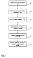
- FIG 3 represents a flowchart of the steps of a method for determining the primary voltage U1j of the transformer 18 implemented by the determination system 22, in particular by the primary current sensors 56A, 56B, 56C and the secondary sensors 58A, 58B, 58C; secondary voltage sensors 59A, 59B, 59C, as well as the information processing unit 60.
- the secondary voltage sensors 59A, 59B, 59C measure the secondary voltages U2j, j being for example equal to a, b, c, of each of the first, second and third secondary connecting conductors 35 , 36, 37 relative to the fourth secondary connecting conductor 38, that is to say the neutral conductor.
- These voltages U2a, U2b, U2c are communicated to the information processing unit 60.
- the primary current sensors 56A, 56B, 56C and the secondary current sensors 58A, 58B, 58C measure the primary currents I1a, I1b, I1c and secondary currents I2a, I2b, 2c of part and of other transformer 18 using the determination system 22 described in the figure 2 .
- the primary and secondary current sensors 56A, 56B, 56C, 58A, 58B, 58C transmit the measurements current via the data link 99, such as a radio link, to the information processing unit 60.
- the current measurements are received by the communication software 72 and taken into account by the acquisition software 73, in order to then be delivered to the calculation software 66, 68, 70.
- the calculation software 66, 68, 70 can, with the aid of the calculation softwares 66, 68, 70, performing the calculation steps for determining the corresponding primary voltages U1a, U1b, U1c of the transformer 18.
- the first calculation software 66 calculates the voltage drop across the transformer 18, on the side of the secondary winding 54.
- this voltage drop is made from the data of the resistive components Ur and reactive Ux of the short-circuit voltage measured in test on the transformer 18, the load factor of the transformer 18 and the power factor of the load of the transformer 18. This voltage drop is calculated from equation [1]. It is expressed as a percentage of the nominal voltage when empty, the latter being indicated on a nameplate, not shown, associated with the transformer 18.
- the complementary measurements of the load factor of the transformer that is to say the measurement of the secondary current I2j, and those of the power factor cos ⁇ of the load will also be taken into account by the information processing unit 60 for the determination of the voltage drop for the load regime considered.
- the second calculation software 68 calculates, during a second calculation step 130, the module of the primary voltage U1j from equation [2].
- the position of the adjusting member Kpos is determined as a function of the number of turns of the primary winding 52 taken into account.
- an adjusting member 20 comprises a plurality of adjustment positions, such as a first P1, a second P2 and a third P3 positions when the electrical transformer 18 is used in France.
- the second position P2 is the position for which a nominal voltage is obtained.
- the selection of the first position P1 allows taking into account a larger number of turns, so the establishment of a primary voltage U1j larger.
- the selection of the third P3 position takes into account a smaller number of turns and therefore imposes a lower primary voltage U1j.
- the adjusting member 20 comprises five or six adjustment positions.
- Kpos is equal to 1 for the second position P2 of the regulator 20, that is to say for the establishment of the nominal value of the primary voltage.
- the adjusting member is in the first position P1 and the value of Kpos is for example 1.025.
- Kpos is worth, for example, 0.975 for an adjusting member in third position P3.
- the determination of the Kpos value is, for example, obtained using the knowledge of the primary nominal voltages corresponding to each position of the regulating member, the secondary nominal voltage, the equation [3], and measuring primary currents I1j and secondary currents I2j.
- the calculation of the first term of the equation [3] makes it possible to identify the position of the regulator Kpos verifying that the ratio between the primary voltages U1j and the secondary voltage U2j are equal to the first term of the equation [3] derived from measurements of primary and secondary currents.
- the calculation of the module of each primary voltage U1j is carried out during step 130 by means of the second calculation software 68.
- This module is a function of the position of the adjusting member Kpos, the ratio of transformation of the primary and secondary nominal voltages to zero, the measurement of each secondary voltage U2j, and the voltage drop calculated in step 120.
- the determination system 22 allows implementation of the determination of each primary voltage U1j in a context of use and improvement of the existing network.
- the establishment of the determination system 22 is possible without power failure thanks, for example, to the use of opening toroids as current sensors. It also requires no physical access to the live parts of the primary side of the transformer 18.
- the establishment of the determination system 22 does not require any adjustment or particular setting throughout its operating life. In particular, the position of the regulator 20 of the transformer is automatically taken into account.
- this determination system 22 makes it possible to calculate the position Kpos of the regulator 20 of the transformer 18 and to make this information accessible remotely and available digitally.
- the offload loaders of distribution transformers are positioned during the installation of the substation according to the rules specific to each distributor, and the recording of their position in a database is only rarely guaranteed.
- the only way to know with certainty the actual position of a plug charger is to go to the station to verify visu.
- This remote read functionality of the Kpos position provides a solution to the network voltage swing problem as it allows the network operator to remotely evaluate the tuning capability available to him at a local level. place of the problem.
- the determination system 22 according to the invention is more precise and less expensive, while being simple to install, easy to use and compatible with the existing network.
Landscapes
- Engineering & Computer Science (AREA)
- Power Engineering (AREA)
- Physics & Mathematics (AREA)
- General Physics & Mathematics (AREA)
- Measurement Of Current Or Voltage (AREA)
Applications Claiming Priority (1)
| Application Number | Priority Date | Filing Date | Title |
|---|---|---|---|
| FR1260655A FR2998060B1 (fr) | 2012-11-09 | 2012-11-09 | Procede et systeme de determination de la tension primaire d'un transformateur, et poste de transformation comportant un tel systeme de determination |
Publications (2)
| Publication Number | Publication Date |
|---|---|
| EP2730929A1 true EP2730929A1 (de) | 2014-05-14 |
| EP2730929B1 EP2730929B1 (de) | 2015-03-04 |
Family
ID=47598966
Family Applications (1)
| Application Number | Title | Priority Date | Filing Date |
|---|---|---|---|
| EP13191995.3A Active EP2730929B1 (de) | 2012-11-09 | 2013-11-07 | Verfahren und System zur Bestimmung der Primärspannung eines Transformators und Trafostation, die ein solches Bestimmungssystem umfasst |
Country Status (5)
| Country | Link |
|---|---|
| EP (1) | EP2730929B1 (de) |
| CN (1) | CN103809009B (de) |
| AU (1) | AU2013254917B2 (de) |
| ES (1) | ES2537929T3 (de) |
| FR (1) | FR2998060B1 (de) |
Cited By (4)
| Publication number | Priority date | Publication date | Assignee | Title |
|---|---|---|---|---|
| CN105353235A (zh) * | 2015-10-15 | 2016-02-24 | 国电南瑞科技股份有限公司 | 一种变压器参数估计方法 |
| FR3030764A1 (fr) * | 2014-12-22 | 2016-06-24 | Schneider Electric Ind Sas | Dispositif et procede de surveillance d'une tension ou d'une intensite, systeme de surveillance d'un tableau electrique, armoire electrique et poste de transformation associes |
| CN112955755A (zh) * | 2018-09-14 | 2021-06-11 | Koa株式会社 | 电流检测装置 |
| EP3789777A4 (de) * | 2019-06-26 | 2021-08-11 | Shandong Electrical Engineering & Equipment Group Intelligent Electric Co., Ltd | Verfahren und vorrichtung zur überwachung eines transformators und speichermedium |
Families Citing this family (3)
| Publication number | Priority date | Publication date | Assignee | Title |
|---|---|---|---|---|
| DE102015104783B4 (de) * | 2015-03-27 | 2017-02-09 | Sma Solar Technology Ag | Verfahren zum Verbinden einer Energieerzeugungsanlage mit einem Mittelspannungsnetz und Energieerzeugungsanlage |
| TWI697166B (zh) * | 2019-01-14 | 2020-06-21 | 義守大學 | 能源調控系統 |
| DE102019105861A1 (de) * | 2019-03-07 | 2020-09-10 | Sma Solar Technology Ag | Verfahren und Vorrichtung zur näherungsweisen Bestimmung von Spannungen an einer Oberspannungsseite eines Transformators |
Citations (2)
| Publication number | Priority date | Publication date | Assignee | Title |
|---|---|---|---|---|
| WO2002097455A1 (en) * | 2001-05-31 | 2002-12-05 | Mcgraw-Edison Company | Current transformer based high voltage measurement method and apparatus |
| US20120061964A1 (en) * | 2011-07-29 | 2012-03-15 | Andreas Kirchner | Power plant control system and method for influencing high voltage characteristics |
Family Cites Families (3)
| Publication number | Priority date | Publication date | Assignee | Title |
|---|---|---|---|---|
| CN1908682B (zh) * | 2006-08-09 | 2010-05-12 | 崇贸科技股份有限公司 | 用于检测变压器的输入电压的检测电路 |
| DE102009048509A1 (de) * | 2009-10-09 | 2011-04-14 | Abb Technology Ag | Verfahren und Vorrichtung zur Ermittlung einer Eingangsspannung an einer Ortsnetzstation eines Stromnetzes |
| CN102539891B (zh) * | 2012-02-22 | 2015-05-27 | 华为技术有限公司 | 变压器原边电压获取方法及装置 |
-
2012
- 2012-11-09 FR FR1260655A patent/FR2998060B1/fr not_active Expired - Fee Related
-
2013
- 2013-11-07 EP EP13191995.3A patent/EP2730929B1/de active Active
- 2013-11-07 ES ES13191995.3T patent/ES2537929T3/es active Active
- 2013-11-07 AU AU2013254917A patent/AU2013254917B2/en active Active
- 2013-11-08 CN CN201310552078.XA patent/CN103809009B/zh active Active
Patent Citations (2)
| Publication number | Priority date | Publication date | Assignee | Title |
|---|---|---|---|---|
| WO2002097455A1 (en) * | 2001-05-31 | 2002-12-05 | Mcgraw-Edison Company | Current transformer based high voltage measurement method and apparatus |
| US20120061964A1 (en) * | 2011-07-29 | 2012-03-15 | Andreas Kirchner | Power plant control system and method for influencing high voltage characteristics |
Cited By (8)
| Publication number | Priority date | Publication date | Assignee | Title |
|---|---|---|---|---|
| FR3030764A1 (fr) * | 2014-12-22 | 2016-06-24 | Schneider Electric Ind Sas | Dispositif et procede de surveillance d'une tension ou d'une intensite, systeme de surveillance d'un tableau electrique, armoire electrique et poste de transformation associes |
| EP3037832A1 (de) * | 2014-12-22 | 2016-06-29 | Schneider Electric Industries SAS | Verfahren und vorrichtung zur überwachung einer spannung oder einer stärke, entsprechendes überwachungssystem einer elektrischen schalttafel, entsprechender schaltschrank und entsprechende transformationseinheit |
| US11125788B2 (en) | 2014-12-22 | 2021-09-21 | Schneider Electric Industries Sas | Device and method for monitoring a voltage or a current, associated system for monitoring an electrical switchboard, electrical enclosure and transformer station |
| CN105353235A (zh) * | 2015-10-15 | 2016-02-24 | 国电南瑞科技股份有限公司 | 一种变压器参数估计方法 |
| CN105353235B (zh) * | 2015-10-15 | 2018-07-06 | 国电南瑞科技股份有限公司 | 一种变压器参数估计方法 |
| CN112955755A (zh) * | 2018-09-14 | 2021-06-11 | Koa株式会社 | 电流检测装置 |
| CN112955755B (zh) * | 2018-09-14 | 2024-02-20 | Koa株式会社 | 电流检测装置 |
| EP3789777A4 (de) * | 2019-06-26 | 2021-08-11 | Shandong Electrical Engineering & Equipment Group Intelligent Electric Co., Ltd | Verfahren und vorrichtung zur überwachung eines transformators und speichermedium |
Also Published As
| Publication number | Publication date |
|---|---|
| FR2998060A1 (fr) | 2014-05-16 |
| CN103809009A (zh) | 2014-05-21 |
| FR2998060B1 (fr) | 2015-01-16 |
| AU2013254917B2 (en) | 2016-11-17 |
| AU2013254917A1 (en) | 2014-05-29 |
| CN103809009B (zh) | 2018-04-27 |
| EP2730929B1 (de) | 2015-03-04 |
| ES2537929T3 (es) | 2015-06-15 |
Similar Documents
| Publication | Publication Date | Title |
|---|---|---|
| EP2730929B1 (de) | Verfahren und System zur Bestimmung der Primärspannung eines Transformators und Trafostation, die ein solches Bestimmungssystem umfasst | |
| EP3126783B1 (de) | Vorrichtung zur messung von mindestens einer physikalischen grösse einer elektrischen installation | |
| EP2687860B1 (de) | Richtungs-Erkennung eines empfindlichen Mittelspannungs-Erdschlusses durch lineare Korrelation | |
| EP2731220B1 (de) | Vorrichtung und Verfahren zur Bestimmung der Spannung und der Leistung jedes Phasenleiters eines Mittelspannungsnetzes | |
| EP0518785B1 (de) | Anordnung zur Überwachung und Messung der Isolierung für elektrische Netze mit isoliertem Nulleiter | |
| EP2816360B1 (de) | Berechnungsverfahren einer elektrischen Messgröße, Transformatoreinheit, die ein solches System umfasst, und Berechnungsverfahren einer elektrischen Messgröße mit einem solchen System | |
| CA2585820A1 (fr) | Localisation de defaut sur un reseau electrique par mesures de tension distribuees | |
| EP3001524B1 (de) | Richtungserfassung des masseschlusses in einem stromverteilungsnetz | |
| WO2020107041A1 (en) | An electrical protection system and a method thereof | |
| FR2991057A1 (fr) | Systeme de mesure de l'energie electrique, poste de transformation comprenant un tel systeme et procede de mesure de l'energie electrique avec un tel systeme | |
| EP0592337B2 (de) | Elektronischer Auslöser mit Erdschutz | |
| EP3123187B1 (de) | Verfahren zum testen eines transformators, elektrisches testsystem, kurzschliessschaltung und anodisierende anordnung | |
| FR2682190A1 (fr) | Procede de detection selective d'un defaut resistant dans un reseau de distribution d'energie electrique et dispositif pour sa mise en óoeuvre. | |
| EP2910958A1 (de) | Störungserkennung, insbesondere einer vorübergehenden Störung, in einem Stromnetz | |
| EP2579611B1 (de) | Verfahren zur lokalisierung von stromentnahmepunkten in einem stromverteilugssystem, entsprechende datenverarbeitungsvorrichtung, entsprechender stromabnehmer und stromzähler | |
| EP0613018B1 (de) | Vorrichtung zur Überwachung und Messung der Isolation eines Stromversorgungsnetzes | |
| FR2700076A1 (fr) | Déclencheur électronique comportant un dispositif de test. | |
| FR2694408A1 (fr) | Dispositif détecteur de défauts sur un réseau de distribution d'énergie électrique aérien. | |
| EP4241353B1 (de) | Vorrichtungen zur überwachung und zum schutz von stromkreisen | |
| EP3001208B1 (de) | System zum erkennen einer elektrischen störung, und entsprechendes verfahren | |
| EP3037832A1 (de) | Verfahren und vorrichtung zur überwachung einer spannung oder einer stärke, entsprechendes überwachungssystem einer elektrischen schalttafel, entsprechender schaltschrank und entsprechende transformationseinheit | |
| EP1279084B1 (de) | Spannungsadaptereinheit | |
| EP3798648B1 (de) | Verfahren zur bestimmung der position einer fehlervorstufe in einem in betrieb befindlichen hochspannungskabel | |
| FR3156256A1 (fr) | Procédé visant à l’équilibrage des phases d’une alimentation en courant électrique polyphasé, et système pour sa mise en œuvre | |
| FR2999294A1 (fr) | Detection directionnelle d'un defaut, notamment dans un reseau a neutre compense |
Legal Events
| Date | Code | Title | Description |
|---|---|---|---|
| PUAI | Public reference made under article 153(3) epc to a published international application that has entered the european phase |
Free format text: ORIGINAL CODE: 0009012 |
|
| 17P | Request for examination filed |
Effective date: 20131107 |
|
| AK | Designated contracting states |
Kind code of ref document: A1 Designated state(s): AL AT BE BG CH CY CZ DE DK EE ES FI FR GB GR HR HU IE IS IT LI LT LU LV MC MK MT NL NO PL PT RO RS SE SI SK SM TR |
|
| AX | Request for extension of the european patent |
Extension state: BA ME |
|
| GRAP | Despatch of communication of intention to grant a patent |
Free format text: ORIGINAL CODE: EPIDOSNIGR1 |
|
| R17P | Request for examination filed (corrected) |
Effective date: 20140916 |
|
| RBV | Designated contracting states (corrected) |
Designated state(s): AL AT BE BG CH CY CZ DE DK EE ES FI FR GB GR HR HU IE IS IT LI LT LU LV MC MK MT NL NO PL PT RO RS SE SI SK SM TR |
|
| RIC1 | Information provided on ipc code assigned before grant |
Ipc: G01R 15/18 20060101AFI20140930BHEP Ipc: G01R 31/06 20060101ALN20140930BHEP |
|
| INTG | Intention to grant announced |
Effective date: 20141017 |
|
| GRAS | Grant fee paid |
Free format text: ORIGINAL CODE: EPIDOSNIGR3 |
|
| GRAA | (expected) grant |
Free format text: ORIGINAL CODE: 0009210 |
|
| AK | Designated contracting states |
Kind code of ref document: B1 Designated state(s): AL AT BE BG CH CY CZ DE DK EE ES FI FR GB GR HR HU IE IS IT LI LT LU LV MC MK MT NL NO PL PT RO RS SE SI SK SM TR |
|
| REG | Reference to a national code |
Ref country code: GB Ref legal event code: FG4D Free format text: NOT ENGLISH |
|
| REG | Reference to a national code |
Ref country code: CH Ref legal event code: EP |
|
| REG | Reference to a national code |
Ref country code: IE Ref legal event code: FG4D Free format text: LANGUAGE OF EP DOCUMENT: FRENCH |
|
| REG | Reference to a national code |
Ref country code: AT Ref legal event code: REF Ref document number: 714330 Country of ref document: AT Kind code of ref document: T Effective date: 20150415 |
|
| REG | Reference to a national code |
Ref country code: DE Ref legal event code: R096 Ref document number: 602013001117 Country of ref document: DE Effective date: 20150416 |
|
| REG | Reference to a national code |
Ref country code: ES Ref legal event code: FG2A Ref document number: 2537929 Country of ref document: ES Kind code of ref document: T3 Effective date: 20150615 |
|
| REG | Reference to a national code |
Ref country code: SE Ref legal event code: TRGR |
|
| REG | Reference to a national code |
Ref country code: AT Ref legal event code: MK05 Ref document number: 714330 Country of ref document: AT Kind code of ref document: T Effective date: 20150304 Ref country code: NL Ref legal event code: VDEP Effective date: 20150304 |
|
| PG25 | Lapsed in a contracting state [announced via postgrant information from national office to epo] |
Ref country code: NO Free format text: LAPSE BECAUSE OF FAILURE TO SUBMIT A TRANSLATION OF THE DESCRIPTION OR TO PAY THE FEE WITHIN THE PRESCRIBED TIME-LIMIT Effective date: 20150604 Ref country code: HR Free format text: LAPSE BECAUSE OF FAILURE TO SUBMIT A TRANSLATION OF THE DESCRIPTION OR TO PAY THE FEE WITHIN THE PRESCRIBED TIME-LIMIT Effective date: 20150304 Ref country code: FI Free format text: LAPSE BECAUSE OF FAILURE TO SUBMIT A TRANSLATION OF THE DESCRIPTION OR TO PAY THE FEE WITHIN THE PRESCRIBED TIME-LIMIT Effective date: 20150304 Ref country code: LT Free format text: LAPSE BECAUSE OF FAILURE TO SUBMIT A TRANSLATION OF THE DESCRIPTION OR TO PAY THE FEE WITHIN THE PRESCRIBED TIME-LIMIT Effective date: 20150304 |
|
| REG | Reference to a national code |
Ref country code: LT Ref legal event code: MG4D |
|
| PG25 | Lapsed in a contracting state [announced via postgrant information from national office to epo] |
Ref country code: RS Free format text: LAPSE BECAUSE OF FAILURE TO SUBMIT A TRANSLATION OF THE DESCRIPTION OR TO PAY THE FEE WITHIN THE PRESCRIBED TIME-LIMIT Effective date: 20150304 Ref country code: AT Free format text: LAPSE BECAUSE OF FAILURE TO SUBMIT A TRANSLATION OF THE DESCRIPTION OR TO PAY THE FEE WITHIN THE PRESCRIBED TIME-LIMIT Effective date: 20150304 Ref country code: LV Free format text: LAPSE BECAUSE OF FAILURE TO SUBMIT A TRANSLATION OF THE DESCRIPTION OR TO PAY THE FEE WITHIN THE PRESCRIBED TIME-LIMIT Effective date: 20150304 Ref country code: GR Free format text: LAPSE BECAUSE OF FAILURE TO SUBMIT A TRANSLATION OF THE DESCRIPTION OR TO PAY THE FEE WITHIN THE PRESCRIBED TIME-LIMIT Effective date: 20150605 |
|
| PG25 | Lapsed in a contracting state [announced via postgrant information from national office to epo] |
Ref country code: NL Free format text: LAPSE BECAUSE OF FAILURE TO SUBMIT A TRANSLATION OF THE DESCRIPTION OR TO PAY THE FEE WITHIN THE PRESCRIBED TIME-LIMIT Effective date: 20150304 |
|
| PG25 | Lapsed in a contracting state [announced via postgrant information from national office to epo] |
Ref country code: SK Free format text: LAPSE BECAUSE OF FAILURE TO SUBMIT A TRANSLATION OF THE DESCRIPTION OR TO PAY THE FEE WITHIN THE PRESCRIBED TIME-LIMIT Effective date: 20150304 Ref country code: RO Free format text: LAPSE BECAUSE OF FAILURE TO SUBMIT A TRANSLATION OF THE DESCRIPTION OR TO PAY THE FEE WITHIN THE PRESCRIBED TIME-LIMIT Effective date: 20150304 Ref country code: CZ Free format text: LAPSE BECAUSE OF FAILURE TO SUBMIT A TRANSLATION OF THE DESCRIPTION OR TO PAY THE FEE WITHIN THE PRESCRIBED TIME-LIMIT Effective date: 20150304 Ref country code: EE Free format text: LAPSE BECAUSE OF FAILURE TO SUBMIT A TRANSLATION OF THE DESCRIPTION OR TO PAY THE FEE WITHIN THE PRESCRIBED TIME-LIMIT Effective date: 20150304 Ref country code: PT Free format text: LAPSE BECAUSE OF FAILURE TO SUBMIT A TRANSLATION OF THE DESCRIPTION OR TO PAY THE FEE WITHIN THE PRESCRIBED TIME-LIMIT Effective date: 20150706 |
|
| PG25 | Lapsed in a contracting state [announced via postgrant information from national office to epo] |
Ref country code: IS Free format text: LAPSE BECAUSE OF FAILURE TO SUBMIT A TRANSLATION OF THE DESCRIPTION OR TO PAY THE FEE WITHIN THE PRESCRIBED TIME-LIMIT Effective date: 20150704 Ref country code: PL Free format text: LAPSE BECAUSE OF FAILURE TO SUBMIT A TRANSLATION OF THE DESCRIPTION OR TO PAY THE FEE WITHIN THE PRESCRIBED TIME-LIMIT Effective date: 20150304 |
|
| REG | Reference to a national code |
Ref country code: DE Ref legal event code: R097 Ref document number: 602013001117 Country of ref document: DE |
|
| PLBE | No opposition filed within time limit |
Free format text: ORIGINAL CODE: 0009261 |
|
| STAA | Information on the status of an ep patent application or granted ep patent |
Free format text: STATUS: NO OPPOSITION FILED WITHIN TIME LIMIT |
|
| PG25 | Lapsed in a contracting state [announced via postgrant information from national office to epo] |
Ref country code: DK Free format text: LAPSE BECAUSE OF FAILURE TO SUBMIT A TRANSLATION OF THE DESCRIPTION OR TO PAY THE FEE WITHIN THE PRESCRIBED TIME-LIMIT Effective date: 20150304 |
|
| 26N | No opposition filed |
Effective date: 20151207 |
|
| PG25 | Lapsed in a contracting state [announced via postgrant information from national office to epo] |
Ref country code: SI Free format text: LAPSE BECAUSE OF FAILURE TO SUBMIT A TRANSLATION OF THE DESCRIPTION OR TO PAY THE FEE WITHIN THE PRESCRIBED TIME-LIMIT Effective date: 20150304 |
|
| PG25 | Lapsed in a contracting state [announced via postgrant information from national office to epo] |
Ref country code: MC Free format text: LAPSE BECAUSE OF FAILURE TO SUBMIT A TRANSLATION OF THE DESCRIPTION OR TO PAY THE FEE WITHIN THE PRESCRIBED TIME-LIMIT Effective date: 20150304 Ref country code: LU Free format text: LAPSE BECAUSE OF FAILURE TO SUBMIT A TRANSLATION OF THE DESCRIPTION OR TO PAY THE FEE WITHIN THE PRESCRIBED TIME-LIMIT Effective date: 20151107 |
|
| REG | Reference to a national code |
Ref country code: IE Ref legal event code: MM4A |
|
| PG25 | Lapsed in a contracting state [announced via postgrant information from national office to epo] |
Ref country code: IE Free format text: LAPSE BECAUSE OF NON-PAYMENT OF DUE FEES Effective date: 20151107 |
|
| REG | Reference to a national code |
Ref country code: FR Ref legal event code: PLFP Year of fee payment: 4 |
|
| PG25 | Lapsed in a contracting state [announced via postgrant information from national office to epo] |
Ref country code: HU Free format text: LAPSE BECAUSE OF FAILURE TO SUBMIT A TRANSLATION OF THE DESCRIPTION OR TO PAY THE FEE WITHIN THE PRESCRIBED TIME-LIMIT; INVALID AB INITIO Effective date: 20131107 Ref country code: BG Free format text: LAPSE BECAUSE OF FAILURE TO SUBMIT A TRANSLATION OF THE DESCRIPTION OR TO PAY THE FEE WITHIN THE PRESCRIBED TIME-LIMIT Effective date: 20150304 |
|
| PG25 | Lapsed in a contracting state [announced via postgrant information from national office to epo] |
Ref country code: CY Free format text: LAPSE BECAUSE OF FAILURE TO SUBMIT A TRANSLATION OF THE DESCRIPTION OR TO PAY THE FEE WITHIN THE PRESCRIBED TIME-LIMIT Effective date: 20150304 |
|
| REG | Reference to a national code |
Ref country code: CH Ref legal event code: PL |
|
| PG25 | Lapsed in a contracting state [announced via postgrant information from national office to epo] |
Ref country code: CH Free format text: LAPSE BECAUSE OF NON-PAYMENT OF DUE FEES Effective date: 20161130 Ref country code: BE Free format text: LAPSE BECAUSE OF NON-PAYMENT OF DUE FEES Effective date: 20151130 Ref country code: LI Free format text: LAPSE BECAUSE OF NON-PAYMENT OF DUE FEES Effective date: 20161130 |
|
| PG25 | Lapsed in a contracting state [announced via postgrant information from national office to epo] |
Ref country code: MT Free format text: LAPSE BECAUSE OF FAILURE TO SUBMIT A TRANSLATION OF THE DESCRIPTION OR TO PAY THE FEE WITHIN THE PRESCRIBED TIME-LIMIT Effective date: 20150304 |
|
| REG | Reference to a national code |
Ref country code: FR Ref legal event code: PLFP Year of fee payment: 5 |
|
| PG25 | Lapsed in a contracting state [announced via postgrant information from national office to epo] |
Ref country code: SM Free format text: LAPSE BECAUSE OF FAILURE TO SUBMIT A TRANSLATION OF THE DESCRIPTION OR TO PAY THE FEE WITHIN THE PRESCRIBED TIME-LIMIT Effective date: 20150304 |
|
| PG25 | Lapsed in a contracting state [announced via postgrant information from national office to epo] |
Ref country code: MK Free format text: LAPSE BECAUSE OF FAILURE TO SUBMIT A TRANSLATION OF THE DESCRIPTION OR TO PAY THE FEE WITHIN THE PRESCRIBED TIME-LIMIT Effective date: 20150304 |
|
| PG25 | Lapsed in a contracting state [announced via postgrant information from national office to epo] |
Ref country code: AL Free format text: LAPSE BECAUSE OF FAILURE TO SUBMIT A TRANSLATION OF THE DESCRIPTION OR TO PAY THE FEE WITHIN THE PRESCRIBED TIME-LIMIT Effective date: 20150304 Ref country code: TR Free format text: LAPSE BECAUSE OF FAILURE TO SUBMIT A TRANSLATION OF THE DESCRIPTION OR TO PAY THE FEE WITHIN THE PRESCRIBED TIME-LIMIT Effective date: 20150304 |
|
| PGFP | Annual fee paid to national office [announced via postgrant information from national office to epo] |
Ref country code: IT Payment date: 20241125 Year of fee payment: 12 Ref country code: ES Payment date: 20241218 Year of fee payment: 12 |
|
| PGFP | Annual fee paid to national office [announced via postgrant information from national office to epo] |
Ref country code: SE Payment date: 20241126 Year of fee payment: 12 |
|
| PGFP | Annual fee paid to national office [announced via postgrant information from national office to epo] |
Ref country code: DE Payment date: 20251126 Year of fee payment: 13 |
|
| PGFP | Annual fee paid to national office [announced via postgrant information from national office to epo] |
Ref country code: GB Payment date: 20251125 Year of fee payment: 13 |
|
| PGFP | Annual fee paid to national office [announced via postgrant information from national office to epo] |
Ref country code: FR Payment date: 20251124 Year of fee payment: 13 |