EP2816843A2 - Mobiles Kommunikationssystem, drahtlose Kommunikationsvorrichtung, mobile Kommunikationsvorrichtung und drahtloses Kommunikationsverfahren - Google Patents
Mobiles Kommunikationssystem, drahtlose Kommunikationsvorrichtung, mobile Kommunikationsvorrichtung und drahtloses Kommunikationsverfahren Download PDFInfo
- Publication number
- EP2816843A2 EP2816843A2 EP14167434.1A EP14167434A EP2816843A2 EP 2816843 A2 EP2816843 A2 EP 2816843A2 EP 14167434 A EP14167434 A EP 14167434A EP 2816843 A2 EP2816843 A2 EP 2816843A2
- Authority
- EP
- European Patent Office
- Prior art keywords
- base station
- mobile station
- broadcast information
- mobile
- lte
- Prior art date
- Legal status (The legal status is an assumption and is not a legal conclusion. Google has not performed a legal analysis and makes no representation as to the accuracy of the status listed.)
- Withdrawn
Links
Images









Classifications
-
- H—ELECTRICITY
- H04—ELECTRIC COMMUNICATION TECHNIQUE
- H04W—WIRELESS COMMUNICATION NETWORKS
- H04W80/00—Wireless network protocols or protocol adaptations to wireless operation
-
- H—ELECTRICITY
- H04—ELECTRIC COMMUNICATION TECHNIQUE
- H04W—WIRELESS COMMUNICATION NETWORKS
- H04W48/00—Access restriction; Network selection; Access point selection
- H04W48/08—Access restriction or access information delivery, e.g. discovery data delivery
- H04W48/12—Access restriction or access information delivery, e.g. discovery data delivery using downlink control channel
-
- H—ELECTRICITY
- H04—ELECTRIC COMMUNICATION TECHNIQUE
- H04W—WIRELESS COMMUNICATION NETWORKS
- H04W72/00—Local resource management
- H04W72/50—Allocation or scheduling criteria for wireless resources
- H04W72/51—Allocation or scheduling criteria for wireless resources based on terminal or device properties
-
- H—ELECTRICITY
- H04—ELECTRIC COMMUNICATION TECHNIQUE
- H04W—WIRELESS COMMUNICATION NETWORKS
- H04W72/00—Local resource management
- H04W72/04—Wireless resource allocation
- H04W72/044—Wireless resource allocation based on the type of the allocated resource
- H04W72/0453—Resources in frequency domain, e.g. a carrier in FDMA
-
- H—ELECTRICITY
- H04—ELECTRIC COMMUNICATION TECHNIQUE
- H04W—WIRELESS COMMUNICATION NETWORKS
- H04W88/00—Devices specially adapted for wireless communication networks, e.g. terminals, base stations or access point devices
- H04W88/08—Access point devices
- H04W88/10—Access point devices adapted for operation in multiple networks, e.g. multi-mode access points
-
- H—ELECTRICITY
- H04—ELECTRIC COMMUNICATION TECHNIQUE
- H04W—WIRELESS COMMUNICATION NETWORKS
- H04W4/00—Services specially adapted for wireless communication networks; Facilities therefor
- H04W4/06—Selective distribution of broadcast services, e.g. multimedia broadcast multicast service [MBMS]; Services to user groups; One-way selective calling services
Definitions
- the present invention is directed to a mobile communications system, a wireless communication apparatus, a mobile communications apparatus, and a wireless communication method.
- the 3GPP which is a standards body, has proposed a communication standard called LTE (Long Term Evolution) which allows communication using a frequency band up to 20 MHz (see, for example, Non Patent Literature (NPTL) 1).
- LTE-A Long Term Evolution-Advanced
- LTE-A Long Term Evolution-Advanced
- next generation mobile communications system is sometimes defined as an extension from its previous generation mobile communications system, rather than being defined as something different from the previous generation mobile communications system.
- base stations and relay stations complying with the next generation communication standard may maintain backward compatibility to accommodate mobile stations complying with the previous generation communication standard.
- LTE-A has been proposed as a communication standard extended from LTE. Accordingly, base stations and relay stations complying with LTE-A may be required to accommodate both mobile stations complying with LTE and mobile stations complying with LTE-A.
- a wireless communication apparatus such as a base station and a relay station
- complying with a next generation communication standard needs to broadcast information not included in broadcast information of a previous generation communication standard to cells under the management of the wireless communication apparatus.
- one frequency band for example, 20 MHz
- multiple frequency bands for example, 20 MHz x 5
- LTE-A LTE-A
- the wireless communication apparatus capable of accommodating both previous and next generation mobile stations broadcast the information not included in the broadcast information of the previous generation communication standard.
- the above-described problem regarding the broadcast information is not limited to the case where a wireless communication apparatus accommodates both mobile stations complying with LTE and mobile stations complying with LTE-A, and can possibly occur in general in the case of accommodating multiple types of mobile stations.
- the present invention aims at providing a mobile communications system, a wireless communication apparatus, a mobile communications apparatus, and a wireless communication method which are capable of efficiently achieving communication control in consideration of the existence of multiple types of mobile stations.
- a mobile communications system including a wireless communication apparatus and a mobile communications apparatus.
- the wireless communication apparatus includes a first generation unit, a second generation unit, and a transmission unit.
- the first generation unit generates first broadcast information which is used in processing of a first-type mobile station and a second-type mobile station.
- the second generation unit generates second broadcast information which is used in processing of the second-type mobile station.
- the transmission unit transmits the first broadcast information through a first broadcast channel and transmits the second broadcast information through a second broadcast channel.
- the mobile communications apparatus which operates as the second-type mobile station, includes a reception unit and a control unit.
- the reception unit receives the first broadcast information transmitted through the first broadcast channel and the second broadcast information transmitted through the second broadcast channel.
- the control unit controls communication with the wireless communication apparatus using the received first and second broadcast information.
- a wireless communication method executed by a mobile communications system which includes a wireless communication apparatus and a mobile communications apparatus.
- the wireless communication apparatus generates first broadcast information which is used in processing of a first-type mobile station and a second-type mobile station, and generates second broadcast information which is used in processing of the second-type mobile station.
- the wireless communication apparatus transmits the first broadcast information through the first broadcast channel and transmits the second broadcast information through the second broadcast channel.
- the mobile communications apparatus which operates as the second-type mobile station, receives the first broadcast information transmitted through the first broadcast channel and the second broadcast information transmitted through the second broadcast channel.
- the mobile communications apparatus controls communication with the wireless communication apparatus using the received first and second broadcast information.
- wireless communication apparatus According to the above-described mobile communications system, wireless communication apparatus, mobile communications apparatus, and wireless communication method, it is possible to efficiently achieve communication control in consideration of the existence of multiple types of mobile stations.
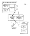
- FIG. 1 illustrates a mobile communications system according to a first embodiment.
- the mobile communications system according to the first embodiment includes a wireless communication apparatus 1 and mobile communications apparatuses 2 and 3.
- the wireless communication apparatus 1 is capable of performing wireless communication with first-type and second-type mobile stations.
- the wireless communication apparatus 1 is, for example, a base station, or a relay station for relaying wireless communication between a base station and a mobile station.
- the mobile communications apparatus 2 is a second-type mobile station, and the mobile communications apparatus 3 is a first-type mobile station.
- the mobile communications apparatuses 2 and 3 are wireless terminals, such as mobile telephones and mobile information terminals.
- the wireless communication apparatus 1 includes a first generation unit 1 a, a second generation unit 1 b, and a transmission unit 1 c.
- the first generation unit 1 a generates first broadcast information to be used by both first-type mobile stations and second-type mobile stations.
- the second generation unit 1 b generates second broadcast information that is not used by first-type mobile stations but used by second-type mobile stations.
- the transmission unit 1c transmits (broadcasts) the first broadcast information generated by the first generation unit 1a through a first broadcast channel 4a.
- the transmission unit 1c transmits (broadcasts) the second broadcast information generated by the second generation unit 1 b through a second broadcast channel 4b, which is different from the first broadcast channel 4a.
- the mobile communications apparatus 2 includes a reception unit 2a and a control unit 2b.
- the reception unit 2a receives the first broadcast information transmitted from the wireless communication apparatus 1 through the first broadcast channel 4a.
- the reception unit 2a receives the second broadcast information transmitted through the second broadcast channel 4b.
- the control unit 2b controls communication with the wireless communication apparatus 1 by referring to both the first and second broadcast information received by the reception unit 2a.
- the mobile communications apparatus 3 receives the first broadcast information, but does not receive the second broadcast information. That is, the mobile communications apparatus 3 controls communication with the wireless communication apparatus 1 without referring to the second broadcast information.
- the wireless communication apparatus 1 may perform wireless communication using multiple frequency bands.
- the wireless communication apparatus 1 may include, in the first broadcast information, information to be used to set up a connection to the wireless communication apparatus 1 using each of the multiple frequency bands (for example, information indicating a bandwidth of each of the frequency bands).
- the wireless communication apparatus 1 may include, in the second broadcast information, information indicating the relationship between the multiple frequency bands and the types of mobile stations.
- the mobile communications apparatus 2 may determine, among the multiple frequency bands, a frequency band available for second-type mobile stations based on the second broadcast information. Then, based on the first broadcast information in terms of the frequency band determined to be available, the mobile communications apparatus 2 may set up a connection to the wireless communication apparatus 1 using the available frequency band.
- the information indicating the relationship between the multiple frequency bands and the types of mobile stations may be defined as information having the following meanings, for example.
- the wireless communication apparatus 1 may attach identification information to each of the multiple frequency bands.
- the identification information may be used in the second broadcast information to indicate the relationship between the multiple frequency bands and the types of the mobile stations.
- the identification information cell IDs (identifications) or unique numbers in a single cell may be used, for example. In the case where cell IDs are used as the identification information, multiple cell IDs are assigned to one cell.
- mobile stations may recognize the individual, multiple frequency bands as (virtually) different cells.
- the first broadcast channel 4a is set, for example, with respect to each of the multiple frequency bands.
- the second broadcast channel 4b may be set with respect to each of the multiple frequency bands, or set for only part of the frequency bands. In the latter case, the second broadcast channel 4b may be set in a predetermined frequency band (for example, a frequency band in the center on the frequency axis), or may be set in a frequency band available for second-type mobile stations.
- the second broadcast channel 4b may be set to be adjacent to the first broadcast channel 4a in a wireless resource region identified by frequency and time.
- the second broadcast channel 4b may be set to be adjacent to a synchronization channel used to transmit a synchronization signal.
- the mobile communication system may be implemented, for example, as an LTE-A system.
- a first-type mobile station may be implemented as a mobile station complying with LTE and a second-type mobile station may be implemented as a mobile station complying with LTE-A.
- the first broadcast channel 4a may be implemented as a broadcast channel commonly defined in both LTE and LTE-A and the second broadcast channel 4b may be implemented as an extended broadcast channel which is not defined in LTE.
- each of the above-described multiple frequency bands is sometimes referred to as a component carrier (CC) or a carrier component (CC).
- CC component carrier
- CC carrier component
- the wireless communication apparatus 1 generates the first broadcast information to be used for processing of first-type and second-type mobile stations and the second broadcast information to be used for processing of second-type mobile stations.
- the first broadcast information is transmitted through the first broadcast channel 4a
- the second broadcast information is transmitted through the second broadcast channel 4b.
- the mobile communications apparatus 2 receives the first broadcast information transmitted through the first broadcast channel 4a and the second broadcast information transmitted through the second broadcast channel 4b. Based on the received first and second broadcast information, communication between the wireless communication apparatus 1 and the mobile communications apparatus 2 is controlled.
- broadcast information that is not used (or is not usable) by first-type mobile stations but used by second-type mobile stations is broadcast through a broadcast channel different from a broadcast channel through which broadcast information to be commonly used by first-type and second-type mobile stations is broadcast. With this, it is possible to efficiently achieve communication control in consideration of the existence of multiple types of mobile stations.
- the mobile communication system in the case of implementing the mobile communication system as an LTE-A system, it is considered that broadcast information defined in LTE is broadcast through a conventional broadcast channel and, then, additional broadcast information defined in LTE-A is broadcast through an extended broadcast channel.
- the mobile communication system allows mobile stations complying with LTE-A to receive the additional broadcast information while allowing mobile stations complying with LTE (i.e., mobile stations not complying with LTE-R) to receive conventional broadcast information. That is, it is possible to achieve an efficient LTE-A system maintaining backward compatibility.
- the second broadcast information information indicating the relationship between the multiple frequency bands and the types of mobile stations and broadcasting the included information. That is, by designating and broadcasting a frequency band desired to be used (or desired not to be used) by second-type mobile stations, it is possible to readily lead second-type mobile stations to use a partial frequency band.
- mobile stations complying with LTE-A are able to use multiple frequency bands while mobile stations complying with LTE use only one frequency band. Accordingly, leading second-type mobile stations to use a partial frequency band is useful also in terms of improving the efficiency in wireless resource use.
- a second embodiment described below is directed to a case in which the wireless communication method according to the first embodiment is applied to an LTE-A system. Note however that it is clear that the above-described wireless communication method is applicable to other types of mobile communications systems.
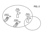
- FIG. 2 illustrates a mobile communications system according to the second embodiment.
- the mobile communications system of the second embodiment includes a base station 100, a relay station 200, and mobile stations 300 and 400.
- the mobile communications system complies with the LTE-A communication standard.
- the base station 100 is a wireless communication apparatus capable of performing wireless communication with the mobile stations 300 and 400 either directly or via the relay station 200.
- the base station 100 is connected to a wired upper-level network (not illustrated) and transfers data between the upper-level network and the mobile stations 300 and 400.
- the base station 100 manages three cells (also sometimes referred to as the "sectors") under its control.
- the base station 100 uses five component carriers (referred to hereinafter as the "CCs") in the wireless communication.
- the relay station 200 is a wireless communication apparatus for relaying wireless communication between the base station 100 and the mobile stations 300 and 400 in the case where the mobile stations 300 and 400 are present in the managed cells.
- the relay station 200 is also sometimes referred to as the "transfer station".
- the relay station 200 uses the same five CCs of the frequency bands that are used by the base station 100.
- the mobile stations 300 and 400 are wireless terminals for performing wireless communication by setting up a connection to the base station 100 or the relay station 200, and are mobile telephones or mobile information terminals, for example.
- the mobile station 300 is capable of receiving data simultaneously using up to five CCs in a downlink (a wireless link from the base station 100 or the relay station 200 to the mobile station 300) and transmitting data simultaneously using up to two CCs in an uplink (a wireless link from the mobile station 300 to the base station 100 or the relay station 200).
- the mobile station 400 transmits and receives data using only one of the CCs in both the downlink and uplink.
- a mobile station which does not use multiple CCs in aggregation is referred to as an LTE mobile station
- a mobile station capable of using multiple CCs in aggregation is referred to as an LTE-A mobile station.
- the mobile station 300 is an LTE-A mobile station
- the mobile station 400 is an LTE mobile station. Both LTE-A mobile stations and LTE mobile stations can set up a connection to the base station 100 and the relay station 200.
- the LTE communication standard is defined in the 3GGP Release 8 specifications and the LTE-A communication standard is defined in the 3GGP Release 10 specifications.
- the 3GGP Release 10 specifications are not all mobile stations complying with the 3GGP Release 10 specifications.
- mobile stations complying with the 3GGP Release 10 specifications may exist.
- mobile stations complying with the 3GGP Release 9 specifications are treated as LTE mobile stations, as in the case of mobile stations complying with the 3GGP Release 8 specifications.
- FIG. 3 illustrates a configuration example of component carriers.
- the base station 100 and the relay station 200 use five CCs, as illustrated in FIG. 3 .
- frequency bands of CC#1 to CC#5 are provided individually for the downlink (DL) and the uplink (UL).
- the pairs of the DL frequency bands and the UL frequency bands are sometimes referred to simply as CC#1 to CC#5.
- each CC has a bandwidth of 20 MHz, and the total bandwidth is 100 MHz.
- the base station 100 and the relay station 200 perform wireless resource allocation (scheduling) for each of CC#1 to CC#5.
- bidirectional communication is achieved using FDD, however, bidirectional communication may be achieved using Time Division Duplex (TDD).
- TDD Time Division Duplex
- five CCs are provided on the frequency axis with no separation between the DL and UL.
- all the CCs have a bandwidth of 20 MHz according to the example of FIG. 3 , however, they may have another bandwidth (for example, 5 MHz, 10 MHz, or 15 MHz). Further, it is not necessary that all the CCs have the same bandwidth.
- the UL wireless resources are provided on the lower frequency side and the DL wireless resources are provided on the higher frequency side.
- the UL wireless resources are provided on the lower frequency side, it is possible to keep the transmission power of the mobile stations 300 and 400 low since a signal of a lower frequency has a smaller propagation loss. Note however that the locations of the UL wireless resources and the DL wireless resources on the frequency axis may be switched.
- the mobile station 300 is capable of performing data transmission and reception using a wider bandwidth (for example, 40 MHz, 60 MHz, 80 MHz, or 100 MHz) than the bandwidth of one CC (for example, 20 MHz).
- all CC#1 to CC#5 may be provided in a single frequency band, such as an 800 MHz band, a 2.5 GHz band, or a 3.5 GHz band, or may be provided separately in multiple different frequency bands.
- Aggregating multiple continuous or discontinuous CCs belonging to the same frequency band is sometimes referred to as the “carrier aggregation”.
- aggregating CCs belonging to different frequency bands is sometimes referred to as the “spectrum aggregation”.
- FIG. 4 illustrates a first example of the carrier aggregation.
- four discontinuous bands each having a bandwidth of 5 MHz and three discontinuous bands each having a bandwidth of 20 MHz are provided in the 3.5 GHz band as bands available for wireless communication.
- the four 5 MHz bands are aggregated to thereby form CC#2 with a bandwidth of 20 MHz.
- one band with a bandwidth of 20 MHz is defined as CC#3.
- the mobile station 300 is able to, for example, use CC#2 and CC#3 as a frequency band of 40 MHz (logically a single frequency band) by carrier aggregation.
- the mobile station 300 uses the four 5 MHz-bandwidth bands and one 20 MHz-bandwidth band belonging to the 3.5 GHz band.
- FIG. 4 illustrates an example of frequency bands belonging to the 3.5 GHz band, it is possible to aggregate and use bands each having a frequency bandwidth smaller than 20 MHz also in a different frequency band, such as the 800 MHz band.
- FIG. 5 illustrates a second example of the carrier aggregation.
- a continuous 80 MHz-bandwidth band is provided in the 3.5 GHz band as a band available for wireless communication.
- the 80 MHz-bandwidth band is divided into four, which are individually defined as CC#2 to CC#5 each having a bandwidth of 20 MHz.
- the mobile station 300 is able to, for example, use CC#2 and CC#3 as a frequency band of 40 MHz (logically a single frequency band) by carrier aggregation. In this case, in reality, the mobile station 300 uses a part of the continuous 80 MHz-bandwidth band belonging to the 3.5 GHz band.
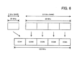
- FIG. 6 illustrates an example of spectrum aggregation.
- a continuous 20 MHz-bandwidth band is provided in the 2 GHz band as a band available for wireless communication.
- a continuous 80 MHz-bandwidth band is provided in the 3.5 GHz band as a band available for wireless communication.
- the 20 MHz-bandwidth band in the 2 GHz band is defined as CC#1
- the 80 MHz-bandwidth band in the 3.5 GHz band is divided into four, which are individually defined as CC#2 to CC#5 each having a bandwidth of 20 MHz.
- the mobile station 300 is able to, for example, use CC#1 to CC#5 as a frequency band of 100 MHz (logically a single frequency band) by spectrum aggregation.
- the mobile station 300 uses the 20 MHz-bandwidth band belonging to the 2 GHz band and the continuous 80 MHz-bandwidth band belonging to the 3.5 GHz band.
- CC#1 may be formed by aggregating multiple bands which belong to the 2 GHz band and each of which has a frequency width smaller than 20 MHz.
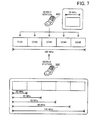
- FIG. 7 illustrates a relationship between mobile stations and component carriers.
- the mobile station 400 is an LTE mobile station, as mentioned above. Accordingly, the mobile station 400 does not apply carrier aggregation or spectrum aggregation, and performs data transmission and reception using one of CC#1 to CC#5. That is, the mobile station 400 uses a frequency band with a bandwidth of up to 20 MHz.
- the mobile station 300 is an LTE-A mobile station. Accordingly, the mobile station 300 is capable of performing data transmission and reception using multiple CCs among CC#1 to CC#5 by applying carrier aggregation or spectrum aggregation. That is, the mobile station 300 is capable of performing data transmission (uplink communication) using a frequency band with a bandwidth of 20 MHz or 40 MHz. In addition, the mobile station 300 is capable of performing data reception (downlink communication) using a frequency band with a bandwidth of 20 MHz, 40 MHz, 60 MHz, 80 MHz, or 100 MHz.
- the base station 100 and the relay station 200 assign an ID to each CC in order to identify CC#1 to CC#5 in the cells under the management.
- the following methods, for example, are conceivable for assigning IDs.
- one cell ID is assigned to each cell.
- five cell IDs are assigned to each cell (sector). Then, the five cell IDs are associated with CC#1 to CC#5 so as to make each CC identifiable.
- a mobile station identifies individual neighboring cells using cell IDs. Assigning five cell IDs to each cell may cause lack of cell IDs in relation to the design of the mobile communication system. In that case, extended cell IDs whose total number is larger than cell IDs defined in the LTE standard are defined, and five extended cell IDs are assigned to each cell. Then, the five extended cell IDs are associated with CC#1 to CC#5 so as to make each CC identifiable.
- Numbers unique at least within a cell are assigned to CC#1 to CC#5 as CC numbers. For example, with respect to each cell, numbers “1", “2", “3”, “4", and "5" are given to CC#1, CC#2, CC#3, CC#4, and CC#5, respectively. Note that it is sufficient if the cell numbers are unique at least within the cell, and numbers may be given to CCs of multiple cells. For example, numbers may be given to CCs of multiple cells managed by the same base station or relay station.
- FIG. 8 illustrates a first example of assigning component carrier identification information.
- the example of FIG. 8 is a case of adopting the first or second method described above.
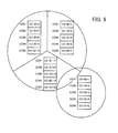
- Cell IDs (or extended cell IDs) "1" to "5" are assigned to CC#1 to CC#5 of a first cell managed by the base station 100.
- Cell IDs (or extended cell IDs) "6" to “10” are assigned to CC#1 to CC#5 of a second cell managed by the base station 100.
- Cell IDs (or extended cell IDs) "11" to "15” are assigned to CC#1 to CC#5 of a third cell managed by the base station 100.
- cell IDs (or extended cell IDs) "16" to "20” are assigned to CC#1 to CC#5 of a cell managed by the relay station 200.
- FIG. 9 illustrates a second example of assigning the component carrier identification information.
- the example of FIG. 9 is a case of adopting the third method described above.
- Cell numbers "1" to "5" are assigned to CC#1 to CC#5 of the first cell managed by the base station 100.
- Cell numbers "6" to “10” are assigned to CC#1 to CC#5 of the second cell managed by the base station 100.
- Cell numbers "11" to “15” are assigned to CC#1 to CC#5 of the third cell managed by the base station 100.
- cell numbers "1" to "5" are assigned to CC#1 to CC#5 of the cell managed by the relay station 200.
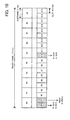
- FIG. 10 illustrates a structural example of a radio frame.
- the radio frame as illustrated in FIG. 10 is transmitted and received between the base station 100 and the mobile station 300/400, and between the relay station 200 and the mobile station 300/400.
- the structure of FIG. 10 is merely an example, and the structure of a radio frame is not limited to this example.
- a radio frame having a cycle of 10 ms includes 10 subframes (Subframes #0 to #9) each having a width of 1 ms. Each subframe includes two slots each having a width of 0.5 ms. That is, the 10 ms-cycle radio frame includes 20 slots (Slot#0 to Slot#19).
- a Primary Synchronization CHannel (P-SCH) and a Secondary Synchronization CHannel (S-SCH) for transmitting synchronization signals are assigned to Slot#0 and Slot#10.
- a Physical Broadcast CHannel (PBCH) and an Extended Physical Broadcast CHannel (E-PBCH) for transmitting (broadcasting) broadcast information are assigned to Slot#1.
- Wireless resources in the radio frame are managed by being subdivided in the time and frequency directions.
- OFDMA Orthogonal Frequency Division Multiple Access
- SC-FDMA Single-Carrier Frequency Division Multiple Access
- Time and frequency wireless resources are assigned to each channel.
- Each slot includes 7 or 6 symbols in the time direction.
- a symbol a signal called "CP (Cyclic Prefix)" is inserted.
- CP Cyclic Prefix
- a CC includes multiple subcarriers.
- FIG. 11 illustrates a first example of allocating an extended physical broadcast channel.
- the vertical direction represents a time axis and the horizontal direction represents a frequency axis.
- the example of FIG. 11 is a case of using normal CPs, that is, a case where 7 symbols are included in one slot.
- a PCFICH Physical Control Format Indicator CHannel
- a PHICH Physical Hybrid automatic repeat request Indicator CHannel
- the PCIFH is a channel for transmitting data indicating the number of symbols to which a Physical Downlink Control CHannel (PDCCH) is assigned.
- the PHICH is a channel for returning an ACK (ACKnowledgement) response or a NACK (Negative ACKnowledgement) response with regard to data reception.
- the PHICH may be assigned to the third symbol.
- the above-described PDCCH is assigned to the first symbol of Slot#0.
- the PDCCH is a channel for transmitting L1/L2 (Layer 1/Layer 2) control information.
- the PDCCH may also be assigned to the second and third symbols.
- the number of symbols for the PDCCH is variable between 1 and 3.
- the above-described S-SCH is assigned to the sixth symbol
- the above-described P-SCH is assigned to the seventh symbol.
- the P-SCH is a channel in which one of a predetermined number (for example, 3) of primary synchronization signal sequences is transmitted.
- the S-SCH is a channel in which one of a predetermined number (for example, 168) of secondary synchronization signal sequences is transmitted.
- the P-SCH sequence and the S-SCH sequence vary from one CC to another. Note that, as described above, the P-SCH and S-SCH are also assigned to Slot#10. Note however that although the P-SCH sequence transmitted in Slot#10 is the same as that transmitted in Slot#0, the S-SCH sequence transmitted in Slot#10 is different from that transmitted in Slot#0.
- the above-described PBCH is assigned to the first to fourth symbols
- the above-described E-PBCH is assigned to the fifth to seventh symbols.
- the E-PBCH is adjacent to the PBCH in the time direction.
- the PBCH is a broadcast channel commonly defined in LTE and LTE-A.
- the E-PBCH is a broadcast channel added in LTE-A. That is, the mobile station 300, which is an LTE-A mobile station, is capable of detecting both the PBCH and the E-PBCH.
- the mobile station 400 which is an LTE mobile station, is able to detect the PBCH but not the E-PBCH.
- Broadcast information transmitted through the PBCH includes information to be used by the mobile station 300/400 to set up a connection to a CC in which the PBCH is provided.
- the broadcast information of the PBCH includes information indicating a frequency bandwidth (for example, 5 MHz, 10 MHz, 15 MHz, or 20 MHz). This is because frequency bandwidths are variable in LTE and LTE-A.
- Broadcast information transmitted by the E-PBCH may include information related to multiple CCs having been configured.
- the base station 100 or the relay station 200 may limit CCs available for LTE mobile stations to set up a connection and CCs available for LTE-A mobile stations to set up a connection.
- information indicating correspondence between CC#1 to CC#5 and types of mobile stations is transmitted by being included in the extended broadcast information.
- the mobile station 300 which is an LTE-A mobile station is able to recognize connection-allowed CCs before having access to the base station 100 or the relay station 200. This sets up the connection processing more efficient.
- Conceivable methods for indicating correspondence between CC#1 to CC#5 and types of mobile stations are, for example: configuring CCs available for LTE-A mobile stations to set up a connection; configuring CCs not available for LTE-A mobile stations to set up a connection; configuring CCs available for LTE mobile stations to set up a connection; and configuring CCs not available for LTE mobile station to set up a connection.
- IDs given to individual CCs may be used to identify the CCs. Note however that the extended broadcast information is not limited to information indicating correspondence between CC#1 to CC#5 and types of mobile stations, and may include various other types of information.
- the S-SCH, P-SCH, PBCH and E-PBCH may be assigned only to partial frequencies (subcarrier), as illustrated in FIG. 11 , rather than being assigned to the entire frequencies (subcarrier) of one CC.
- these channels are assigned to frequencies near the center of the CC.
- the channel assignment is made to frequencies near the center of the CC, not to frequencies near the boundary of the CC, in order to facilitate channel detection performed by the mobile station 300/400.
- Frequencies assigned to the E-PBCH may be the same as, or different from, those assigned to the PBCH.
- a Reference Signal which is a known pilot signal is transmitted using a part of resources different from the wireless resources used for the above-described channels.
- the mobile station 300/400 is able to measure the received power and received quality.
- FIG. 12 illustrates a second example of allocating the extended physical broadcast channel.
- the allocating example of FIG. 12 is the same as the example illustrated in FIG. 11 except for the location in which the E-PBCH is set.
- the E-PBCH is assigned to the fourth and fifth symbols of Slot#0.
- the E-PBCH is adjacent to the S-SCH in the time direction. Frequencies assigned to the E-PBCH may be the same as, or different from, those assigned to the S-SCH.
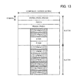
- FIG. 13 illustrates a third example of allocating the extended physical broadcast channel.
- the allocating example of FIG. 13 is the same as the examples illustrated in FIGs. 11 and 12 except for the location in which the E-PBCH is set.
- the E-PBCH is assigned to both the fourth and fifth symbols of Slot#0 and the fifth to seventh symbols of Slot#1.
- the E-PBCH is adjacent to the S-SCH and the PBCH in the time direction.
- Subcarrier frequencies assigned to the E-PBCH may be the same as, or different from, those assigned to the S-SCH and the PBCH.
- Wireless resources assigned to the E-PBCH may be made variable according to the amount of extended broadcast information to be transmitted.
- setting the E-PBCH adjacent to at least one of the synchronization channel and the PBCH in the time direction facilitates the mobile station 300 to detect the E-PBCH.
- the adjacency setting may be made not in the time direction but in the frequency direction.
- the E-PBCH may be set to be adjacent to none of the synchronization channel and the PBCH.
- FIG. 14 illustrates a fourth example of allocating the extended physical broadcast channel.
- the allocating example of FIG. 14 is the same as the examples illustrated in FIGs. 11 to 13 except for the location in which the E-PBCH is set.
- the E-PBCH is assigned to the seventh symbol of Slot#1.
- the E-PBCH is not adjacent to the PBCH.
- Frequencies assigned to the E-PBCH may be the same as, or different from, those assigned to the PBCH.
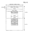
- FIG. 15 illustrates a fifth example of allocating the extended physical broadcast channel.
- the allocating example of FIG. 15 is the same as the examples illustrated in FIGs. 11 to 14 except for the location in which the E-PBCH is set.
- the E-PBCH is assigned to the fourth symbol of Slot#0.
- the E-PBCH is not adjacent to the S-SCH. Frequencies assigned to the E-PBCH may be the same as, or different from, those assigned to the S-SCH.
- FIG. 16 illustrates a sixth example of allocating the extended physical broadcast channel.
- the allocating example of FIG. 16 is the same as the examples illustrated in FIGs. 11 to 15 except for the location in which the E-PBCH is set.
- the E-PBCH is assigned to the sixth symbol of Slot#1.
- the E-PBCH is not adjacent to the PBCH.
- Frequencies assigned to the E-PBCH may be the same as, or different from, those assigned to the PBCH.
- FIGs. 11 to 16 above take as an example the case of using a normal CP as the CP (i.e., the case where 7 symbols are included in one slot).
- the E-PBCH may be set based on similar considerations. In that case, the E-PBCH is assigned to, for example, the fifth and sixth symbols of Slot#1 in the method of FIG. 11 ; the fourth symbol of Slot#0 in the method of FIG. 12 ; the fourth symbol of Slot#0 and the fifth and sixth symbols of Slot#1 in the method of FIG. 13 ; and the sixth symbol of Slot#1 in the method of FIG. 14 .
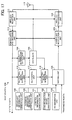
- FIG. 17 is a block diagram illustrating a base station.
- the base station 100 includes a transmitting and receiving antenna 111; a wireless reception unit 112; a demodulation and decoding unit 113; a quality information extraction unit 114; a scheduler 115; an RA control signal extraction unit 116; an RA control unit 117; an RA control signal generation unit 118; a broadcast information generation unit 119; an extended broadcast information generation unit 120; a control information generation unit 121; a synchronization signal generation unit 122; an RS generation unit 123; a mapping unit 124; a coding and modulation unit 125; and a wireless transmission unit 126.
- the transmitting and receiving antenna 111 receives wireless signals transmitted by the relay station 200 and the mobile station 300/400 and outputs the wireless signals to the wireless reception unit 112. In addition, the transmitting and receiving antenna 111 outputs a transmission signal acquired from the wireless transmission unit 126. Note that, instead of the two-way transmitting and receiving antenna, a transmitting antenna and a receiving antenna may be separately provided in the base station 100. In addition, diversity transmission may be employed using multiple transmitting and receiving antennas.
- the wireless reception unit 112 performs wireless signal processing on a signal acquired from the transmitting and receiving antenna 111 and converts the high-frequency wireless signal into a baseband signal as a low-frequency signal (down-conversion).
- the wireless reception unit 112 includes, for example, a Low Noise Amplifier (LNA), a frequency converter, a Band Pass Filter (BPF), an A/D (Analog to Digital) converter. Frequency bands for reception are notified of by the scheduler 115.
- LNA Low Noise Amplifier
- BPF Band Pass Filter
- A/D Analog to Digital
- the demodulation and decoding unit 113 demodulates and error correction decodes the baseband signal acquired from the wireless reception unit 112, and then outputs obtained data (including user data and control information).
- the demodulation and decoding are performed by methods corresponding to a predetermined Modulation and Coding Scheme (MCS) or an MCS notified of by the scheduler 115.
- MCS Modulation and Coding Scheme
- Choices for the modulation scheme include digital modulation schemes such as QPSK (Quadrature Phase Shift Keying) and 16QAM (Quadrature Amplitude Modulation).
- Choices for the coding scheme include turbo coding and Low Density Parity Check (LDPC) coding.
- the extracted user data is converted into packet format and then transferred to the upper-level network.
- the quality information extraction unit 114 extracts a wireless quality measurement report which is control information transmitted by the mobile station 300/400. Subsequently, the quality information extraction unit 114 outputs the extracted measurement report to the scheduler 115.
- the scheduler 115 allocates wireless resources to the mobile station 300/400 based on the measurement report acquired from the quality information extraction unit 114. Subsequently, the scheduler 115 notifies the wireless reception unit 112, the demodulation and decoding unit 113, the RA control signal generation unit 118, the coding and modulation unit 125, and the wireless transmission unit 126 of the wireless resource allocation status. In addition, the scheduler 115 adaptively selects an MCS based on the measurement report. Then, the scheduler 115 notifies the demodulation and decoding unit 113 and the coding and modulation unit 125 of the selected MCS.
- the RA control signal extraction unit 116 extracts a control signal transmitted by the mobile station 300/400 to the base station 100 at the time of random access (RA).
- the random access is a procedure performed between the mobile station 300/400 and the base station 100 when the mobile station 300/400 sets up a connection to the base station 100.
- the control signal extracted by the RA control signal extraction unit 116 includes a random access preamble signal transmitted through a Physical Random Access CHannel (PRACH) provided in a UL radio frame and a scheduled transmission signal transmitted through a Physical Uplink Shared CHannel (PUSCH).
- PRACH Physical Random Access CHannel
- PUSCH Physical Uplink Shared CHannel
- the RA control unit 117 controls random access based on the control signal extracted by the RA control signal extraction unit 116. Specifically, when a random access preamble signal is detected, the RA control unit 117 determines whether a CC used for transmitting the signal corresponds to the type of a source mobile station (LTE mobile station or LTE-A mobile station), and decides whether to accept access or not. Subsequently, the RA control unit 117 notifies the RA control signal generation unit 118 of the decision. In addition, when a scheduled transmission signal is properly detected, the RA control unit 117 notifies the RA control signal generation unit 118 accordingly.
- LTE mobile station LTE mobile station or LTE-A mobile station
- the RA control signal generation unit 118 Based on the notification from the scheduler 115 and the RA control unit 117, the RA control signal generation unit 118 generates a control signal to be transmitted to the mobile station 300/400 at the time of random access. Specifically, the RA control signal generation unit 118 generates, as a response to the random access preamble signal, a random access response signal indicating whether to accept the access. In addition, the RA control signal generation unit 118 generates a contention resolution signal as a response to the scheduled transmission signal.
- the broadcast information generation unit 119 generates, with respect to each CC, broadcast information to be transmitted (broadcast) through the PBCH.
- the broadcast information includes, for example, information indicating a frequency bandwidth of the corresponding CC.
- the extended broadcast information generation unit 120 generates extended broadcast information to be transmitted (broadcast) through the E-PBCH.
- the extended broadcast information includes information indicating correspondence between CC#1 to CC#5 and the types of mobile stations.
- the control information generation unit 121 generates L1/L2 control information to be transmitted through the PDCCH. This control information includes, for example, information indicating a result of UL wireless resource allocation and an MCS to be applied.
- the synchronization signal generation unit 122 generates a P-SCH sequence and an S-SCH sequence with respect to each CC.
- the RS generation unit 123 generates a reference signal which is a known signal.
- the mapping unit 124 maps, in a DL radio frame, user data received from the upper-level network and control information or control signals generated by the RA control signal generation unit 118, the broadcast information generation unit 119, the extended broadcast information generation unit 120, the control information generation unit 121, the synchronization signal generation unit 122, and the RS generation unit 123. Then, the mapping unit 124 successively outputs the mapped data to the coding and modulation unit 125.
- the coding and modulation unit 125 performs error correction coding and modulation on the data acquired from the mapping unit 124, and generates a baseband signal to be a transmission signal and then outputs the baseband signal to the wireless transmission unit 126.
- a predetermined MCS or an MCS notified of by the scheduler 115 is used.
- Choices for the modulation scheme include digital modulation schemes such as QPSK and 16QAM.
- Choices for the coding scheme include turbo coding and LDPC coding.
- the wireless transmission unit 126 performs wireless signal processing on the transmission signal acquired from the coding and modulation unit 125 and converts the baseband signal as a low-frequency signal into a high-frequency wireless signal (up-conversion).
- the wireless transmission unit 126 includes, for example, a D/A (Digital to Analog) converter, a frequency converter, a BPF, and a power amplifier. Frequency bands for transmission are notified of by the scheduler 115.
- FIG. 18 is a block diagram of a relay station.
- the relay station 200 includes transmitting and receiving antennas 211 and 228; a wireless reception unit 212; a demodulation and decoding unit 213; a quality information extraction unit 214; a scheduler 215; an RA control signal extraction unit 216; an RA control unit 217; an RA control signal generation unit 218; a broadcast information generation unit 219; an extended broadcast information generation unit 220; a control information generation unit 221; a synchronization signal generation unit 222; an RS generation unit 223; a mapping unit 224; a coding and modulation unit 225; a wireless transmission unit 226; and a base station side communication unit 227.
- Each of modules from the transmitting and receiving antenna 211 to the wireless transmission unit 226 performs similar processing to that of a module with the same name in the base station 100 of FIG. 18 . These modules perform wireless communication processing between the relay station 200 and the mobile station 300/400.
- the base station side communication unit 227 performs wireless communication processing between the relay station 200 and the base station 100.
- the base station side communication unit 227 performs error correction coding, modulation, and up-conversion on the user data (transmission data of the mobile station 300/400) acquired from the demodulation and decoding unit 213, and then outputs an obtained transmission signal to the transmitting and receiving antenna 228.
- the base station side communication unit 227 performs down-conversion, demodulation, and error correction decoding on a wireless signal acquired from the transmitting and receiving antenna 228, and then outputs extracted user data (transmission data of the base station 100) to the mapping unit 224.
- the transmitting and receiving antenna 228 receives a wireless signal transmitted by the base station 100 and outputs the received signal to the base station side communication unit 227. In addition, the transmitting and receiving antenna 228 outputs a transmission signal acquired from the base station side communication unit 227. Note that instead of providing the transmitting and receiving antenna 211 and the transmitting and receiving antenna 228 separately, a transmitting and receiving antenna capable of performing wireless communication with both the base station 100 and the mobile station 300/400 in parallel may be provided.
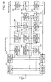
- FIG. 19 is a block diagram of a mobile station.
- the mobile station 300 includes a transmitting and receiving antenna 311; a wireless reception unit 312; a demodulation and decoding unit 313; a control information extraction unit 314; a broadcast information extraction unit 315; an extended broadcast information extraction unit 316; a synchronization signal extraction unit 317; a synchronization control unit 318; a terminal control unit 319; an RS extraction unit 320; a quality measuring unit 321; a quality information generation unit 322; a received power measuring unit 323; a cell selecting unit 324; an RA control signal extraction unit 325; an RA control unit 326; an RA control signal generation unit 327; a coding and modulation unit 328; and a wireless transmission unit 329.
- the transmitting and receiving antenna 311 receives wireless signals transmitted by the base station 100 and the relay station 200, and then outputs the received signals to the wireless reception unit 312. In addition, the transmitting and receiving antenna 311 outputs a transmission signal acquired from the wireless transmission unit 329. Note that, instead of the two-way transmitting and receiving antenna, a transmitting antenna and a receiving antenna may be separately provided in the mobile station 300. In addition, diversity transmission may be employed using multiple transmitting and receiving antennas.
- the wireless reception unit 312 performs wireless signal processing on a signal acquired from the transmitting and receiving antenna 311 and converts the high-frequency wireless signal into a baseband signal as a low-frequency signal (down-conversion).
- the wireless reception unit 312 includes, for example, an LNA, a frequency converter, a BPF, an A/D converter. Frequency bands for reception are notified of by the terminal control unit 319.
- the demodulation and decoding unit 313 demodulates and error correction decodes the baseband signal acquired from the wireless reception unit 312, and then outputs obtained data (including user data and control information).
- the demodulation and decoding are performed by methods corresponding to a predetermined MCS or an MCS notified of by the terminal control unit 319.
- the control information extraction unit 314 extracts L1/L2 control information transmitted by the base station 100 or the relay station 200 through the PDCCH.
- the control information includes, for example, information indicating UL wireless resource allocation and an MCS to be applied. Then, the control information extraction unit 314 outputs the extracted control information to the terminal control unit 319.
- the broadcast information extraction unit 315 extracts, with respect to each CC, broadcast information broadcast by the base station 100 or the relay station 200 through the PBCH.
- the broadcast information includes, for example, information indicating a frequency bandwidth of the CC in which the broadcast information is transmitted.
- the broadcast information extraction unit 315 outputs the extracted broadcast information to the terminal control unit 319.
- the extended broadcast information extraction unit 316 extracts extended broadcast information broadcast by the base station 100 or the relay station 200 through the E-PBCH.
- the E-PBCH is provided to at least one CC.
- the extended broadcast information includes information indicating correspondence between CC#1 to CC#5 and types of mobile stations.
- the extended broadcast information extraction unit 316 outputs the extracted extended broadcast information to the synchronization control unit 318, the terminal control unit 319, the quality measuring unit 321, the received power measuring unit 323, and the cell selecting unit 324.
- the synchronization signal extraction unit 317 extracts, with respect to each CC, synchronization signals (primary and secondary synchronization signals) transmitted by the base station 100 or the relay station 200 via the P-SCH and the S-SCH. Then, the synchronization signal extraction unit 317 outputs the synchronization signals to the synchronization control unit 318.
- the synchronization control unit 318 detects a timing of 10-ms radio frame based on the synchronization signals extracted by the synchronization signal extraction unit 317. In addition, the synchronization control unit 318 detects a timing of 0.5-ms slot. Subsequently, the synchronization control unit 318 notifies the wireless reception unit 312, the demodulation and decoding unit 313, the RS extraction unit 320, the coding and modulation unit 328, and the wireless transmission unit 329 of the detected radio frame and slot timings, and performs feedback to the synchronization signal extraction unit 317.
- the synchronization control unit 318 specifies P-SCH sequences and S-SCH sequences used by the base station 100 or the relay station 200, and then specifies cell IDs based on the combinations of the sequences. Subsequently, the synchronization control unit 318 notifies the cell selecting unit 324 of the specified cell IDs.
- the terminal control unit 319 determines CCs available for LTE-A mobile stations by referring to the extended broadcast information extracted by the extended broadcast information extraction unit 316. In addition, the terminal control unit 319 controls access to the base station 100 or the relay station 200 by referring to the broadcast information extracted by the broadcast information extraction unit 315. In addition, the terminal control unit 319 refers to the control information extracted by the control information extraction unit 314 to thereby determine wireless resources allocated to the mobile station 300 as well as determine an applied MCS. Subsequently, the terminal control unit 319 controls operation of the wireless reception unit 312, the demodulation and decoding unit 313, the coding and modulation unit 328, and the wireless transmission unit 329.
- the RS extraction unit 320 extracts a reference signal transmitted by the base station 100 or the relay station 200 based on the radio frame and slot timings detected by the synchronization control unit 318. Then, the RS extraction unit 320 outputs the extracted reference signal to the quality measuring unit 321 and the received power measuring unit 323.
- the quality measuring unit 321 uses the reference signal extracted by the RS extraction unit 320 to measure reception quality of the CCs available to LTE-A mobile stations, which CCs are indicated by the extended broadcast information. Reception quality of CCs not available for LTE-A mobile stations need not be measured. Then, the quality measuring unit 321 notifies the quality information generation unit 322 of the measurement results. The quality measuring unit 321 feeds the measurement results to the RS extraction unit 320.
- an SINR Signal to Interference and Noise Ratio
- the quality information generation unit 322 generates control information (measurement report) indicating the reception quality measured by the quality measuring unit 321.
- control information indicating the reception quality measured by the quality measuring unit 321.
- a CQI Channel Quality Indication
- a discrete value may be used, for example.
- the received power measuring unit 323 measures received power (receiving electric field intensity) of each of CC#1 to CC#5 using the reference signal extracted by the RS extraction unit 320. In the case where at the time of the measurement, CCs available for LTE-A mobile stations are notified of based on the extended broadcast information extracted by the extended broadcast information extraction unit 316, received power of CCs not available for LTE-A mobile stations need not be measured. Subsequently, the received power measuring unit 323 notifies the cell selecting unit 324 of the measurement results.
- the cell selecting unit 324 selects a cell to which the mobile station 300 sets up a connection based on the cell IDs of the neighboring cells specified by the synchronization control unit 318 and the received power measured by the received power measuring unit 323. Preferably, the cell selecting unit 324 selects a cell having the highest received power. In addition, the cell selecting unit 324 selects a CC to be used for random access based on the extended broadcast information extracted by the extended broadcast information extraction unit 316 and the received power of each CC. Preferably, the cell selecting unit 324 selects, among connection available CCs, a CC having the highest received power. Subsequently, the cell selecting unit 324 notifies the RA control unit 326 of the connection cell and the CC to be used.
- the RA control signal extraction unit 325 extracts a control signal transmitted by the base station 100 or the relay station 200 through the PDSCH at the time of random access.
- the control signal includes a random access response signal and a contention resolution signal. Then, the RA control signal extraction unit 325 outputs the extracted control signal to the RA control unit 326.
- the RA control unit 326 On receiving notification of the connection cell and the CC to be used from the cell selecting unit 324, the RA control unit 326 instructs the RA control signal generation unit 327 to transmit a random access preamble signal using the notified CC. Further, the RA control unit 326 instructs the RA control signal extraction unit 325 to extract a response control signal. When the random access response signal is extracted by the RA control signal extraction unit 325, the RA control unit 326 instructs the RA control signal generation unit 327 to transmit a scheduled transmission signal.
- the RA control signal generation unit 327 In response to the instruction from the RA control unit 326, the RA control signal generation unit 327 generates the random access preamble signal to be transmitted through the PRACH. In addition, in response to the instruction from the RA control unit 326, the RA control signal generation unit 327 generates the scheduled transmission signal to be transmitted through the PUSCH.
- the coding and modulation unit 328 performs error correction coding and modulation on the user data to be transmitted to the base station 100 or the relay station 200, the measurement report generated by the quality information generation unit 322, and the control signal generated by the RA control signal generation unit 327, and also maps these items in UL wireless resources allocated to the mobile station 300. For the coding and modulation, a predetermined MCS or an MCS notified of by the terminal control unit 319 is used. Subsequently, the coding and modulation unit 328 outputs, to the wireless transmission unit 329, a baseband signal as a transmission signal.
- the wireless transmission unit 329 performs wireless signal processing on the transmission signal acquired from the coding and modulation unit 328 and converts the baseband signal as a low-frequency signal into a high-frequency wireless signal (up-conversion).
- the wireless transmission unit 329 includes, for example, a D/A converter, a frequency converter, a BPF, and a power amplifier. Frequency bands for transmission are notified of by the terminal control unit 319.
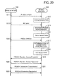
- FIG. 20 is a sequence diagram illustrating a first example of setting up a connection from a mobile station to a base station.
- the sequence represents the case where the mobile station 300, which is an LTE-A mobile station, sets up a connection to the base station 100.
- a similar sequence takes place in the case where the mobile station 300 sets up a connection to the relay station 200.
- Step S11 The base station 100 transmits synchronization signals through the P-SCH and S-SCH of each of CC#1 to CC#5.
- the base station 100 transmits different synchronization signals with respect to each CC.
- the base station 100 transmits synchronization signals with respect to each cell.
- the relay station 200 transmits synchronization signals.
- Step S12 Based on the synchronization signals transmitted by the base station 100, the mobile station 300 detects a timing of radio frames with respect to each cell so as to be synchronized with the base station 100. In the case where timings of radio frames of CC#1 to CC#5 are synchronized with each other, the mobile station 300 does not have to perform the timing detection for all the CCs. In a similar fashion, the mobile station 300 becomes synchronized with the relay station 200.
- Step S13 The base station 100 transmits a reference signal, which is a pilot signal, in each of CC#1 to CC#5.
- the reference signals transmitted in CC#1 to CC#5 may be all the same.
- the relay station 200 transmits reference signals.
- Step S14 Based on the reference signals transmitted by the base station 100, the mobile station 300 measures received power from the base station 100 with respect to each cell.
- the received power may be measured for one of the CCs or multiple CCs. In the former case, a frequency band to be measured may be determined in advance. In the latter case, a maximum or average received power value of the multiple CCs may be defined as the received power from the base station 100.
- the mobile station 300 measures received power from the relay station 200.
- Step S15 Based on the received power measured in Step S14, the mobile station 300 selects a cell to set up a connection. Preferably, the mobile station 300 selects a cell having the highest received power. Assume here that the mobile station 300 selects a cell managed by the base station 100.
- Step S16 The base station 100 transmits (broadcasts) broadcast information through the PBCH of each of CC#1 to CC#5. In addition, the base station 100 transmits (broadcasts) extended broadcast information through the E-PBCH which is provided at least one of CC#1 to CC#5.
- Step S17 Based on the extended broadcast information transmitted (broadcast) by the base station 100, the mobile station 300 determines, among CC#1 to CC#5, one or more CCs to which LTE-A mobile stations are able to set up a connection.
- Step S18 Among the one or more CCs determined to be available for LTE-A mobile stations in Step S17, the mobile station 300 selects a CC to be used for random access. In the case where there are multiple CCs, arbitrary one may be selected, or one with the highest received power may be selected.
- a CC to be used is selected after the selection of a cell to which the mobile station 300 sets up a connection.
- the cell selection and the CC selection may be performed at the same time.
- the mobile station 300 may measure received power for all CCs of detected neighboring cells and select, among the CCs, a CC available for LTE-A mobile stations to set up a connection and yielding the highest received power.
- the mobile station 300 may determine, with respect to each neighboring cell, CCs available for LTE-A mobile stations to set up a connection, and then measure received power of the CCs so as to select a CC having higher received power.
- Step S19 The mobile station 300 checks information to be used for setting up a connection (for example, information indicating a frequency bandwidth) to the CC selected in Step S18, which information is included in broadcast information corresponding to the selected CC. Subsequently, the mobile station 300 transmits a random access preamble to the base station 100 through the PRACH provided in the UL radio frame of the selected CC.
- information to be used for setting up a connection for example, information indicating a frequency bandwidth
- Step S20 In the case where the CC with which the random access preamble is received is available for LTE-A mobile stations to set up a connection and the base station 100 has available wireless resources to accommodate the mobile station 300, the base station 100 allows the mobile station 300 to set up a connection. In the case of allowing the connection, the base station 100 transmits a random access response indicating a connection setup permission through the PDSCH provided in the DL radio frame of the CC with which the random access preamble is received. At that point, the base station 100 allocates, to the mobile station 300, UL wireless resources to be used in Step S21.
- Step S21 In order to determine whether communication is normally performed, the mobile station 300 transmits scheduled transmission, which is a predetermined message, to the base station 100 using the UL wireless resources (PUSCH) allocated in Step S20.
- PUSCH UL wireless resources
- Step S22 The base station 100 determines whether to have correctly received the scheduled transmission. Subsequently, the base station 100 transmits, as a response message, contention resolution indicating a reception result to the mobile station 300 through the PDSCH.
- the mobile station 300 which is an LTE-A mobile station is able to determine a CC available for LTE-A mobile stations before making random access. Accordingly, the mobile station 300 does not make an attempt to set up a connection to CCs unavailable for LTE-A mobile stations, which eliminates useless random access procedures. In addition, by preliminarily determining CCs available for LTE-A mobile stations, the mobile station 300 is able to narrow down CCs for the received power measurement, which reduces the processing load of the mobile station 300.
- the mobile station 400 which is an LTE mobile station is not able to refer to the extended broadcast information. Accordingly, even in the case where the base station 100 or the relay station 200 limits CCs available for LTE mobile stations, the mobile station 400 is not able to determine, before making random access, which CC is available for LTE mobile stations. Therefore, the mobile station 400 may cause a random access failure.
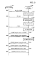
- FIG. 21 is a sequence diagram illustrating a second example of setting up a connection from a mobile station to a base station.
- the sequence represents the case where the mobile station 400, which is an LTE mobile station, sets up a connection to the base station 100.
- a similar sequence takes place in the case where the mobile station 400 sets up a connection to the relay station 200.
- Step S31 The base station 100 transmits synchronization signals through the P-SCH and S-SCH of each of CC#1 to CC#5.
- the base station 100 transmits different synchronization signals with respect to each CC.
- the base station 100 transmits synchronization signals with respect to each cell.
- the relay station 200 transmits synchronization signals.
- Step S32 Based on the synchronization signal transmitted by the base station 100, the mobile station 400 detects a timing of radio frame with respect to each cell so as to be synchronized with the base station 100.
- the mobile station 400 may recognize CC#1 to CC#5 as cells (virtually) different from each other. In a similar fashion, the mobile station 400 becomes synchronized with the relay station 200.
- Step S33 The base station 100 transmits a reference signal, which is a pilot signal, in each of CC#1 to CC#5. In a similar fashion, the relay station 200 transmits reference signals.
- Step S34 Based on the reference signals transmitted by the base station 100, the mobile station 400 measures received power from the base station 100 with respect to each cell and each CC. In a similar fashion, the mobile station 300 measures received power from the relay station 200.
- Step S35 Based on the received power measured in Step S34, the mobile station 400 selects a cell to set up a connection. Preferably, the mobile station 400 selects a cell having the highest received power. Assume here that the mobile station 400 selects a cell managed by the base station 100.
- Step S36 The base station 100 transmits (broadcasts) broadcast information through the PBCH of each of CC#1 to CC#5.
- Step S37 Among CC#1 to CC#5 of the cell selected in Step S35, the mobile station 400 selects a CC to be used for random access. Among CC#1 to CC#5, an arbitrary one may be selected, or one with the highest received power may be selected. Note that in the case of recognizing CC#1 to CC#5 as cells (virtually) different from each other, the mobile station 400 may perform the cell selection and CC selection at the same time based on the received power of each of the CCs.
- Step S38 The mobile station 400 checks information to be used for setting up a connection (for example, information indicating a frequency bandwidth) to the CC selected in Step S37, which information is included in broadcast information corresponding to the selected CC. Subsequently, the mobile station 400 transmits a random access preamble to the base station 100 though the PRACH provided in the UL radio frame of the selected CC.
- the selected CC is a CC to which LTE mobile stations are unable to set up a connection.
- Step S39 In the case where the CC with which the random access preamble is received is not available for LTE mobile stations to set up a connection, the base station 100 rejects the connection. In the case of rejecting the connection, the base station 100 transmits a random access response indicating connection rejection through the PDSCH provided in the DL radio frame of the CC with which the random access preamble is received. Alternatively, the base station 100 does not make a response to the random access preamble.
- Step S40 The mobile station 400 determines that the random access is failed in the case of receiving a random access response indicating a connection rejection or receiving no response within a predetermined time period after transmission of the random access preamble. Subsequently, the mobile station 400 selects another CC of the cell, different from one selected in Step S35.
- Step S41 The mobile station 400 checks information to be used for setting up a connection to the CC selected in Step S40, which information is included in broadcast information corresponding to the selected CC. Subsequently, the mobile station 400 transmits a random access preamble to the base station 100 through the PRACH provided in the UL radio frame of the selected CC. Assume here that the selected CC is a CC to which LTE mobile stations are able to set up a connection.
- Step S42 In the case where the CC with which the random access preamble is received is available for LTE mobile stations to set up a connection and the base station 100 has available wireless resources to accommodate the mobile station 400, the base station 100 allows the mobile station 400 to set up a connection. In the case of allowing the connection, the base station 100 transmits a random access response indicating a connection setup permission through the PDSCH provided in the DL radio frame of the CC with which the random access preamble is received. At that point, the base station 100 allocates, to the mobile station 400, UL wireless resources to be used in Step S43.
- Step S43 In order to determine whether communication is correctly performed, the mobile station 400 transmits scheduled transmission to the base station 100 using the UL wireless resources (PUSCH) allocated in Step S42.
- PUSCH UL wireless resources
- Step S44 The base station 100 determines whether to have correctly received the scheduled transmission. Subsequently, the base station 100 transmits, as a response message, contention resolution indicating a reception result to the mobile station 400 through the PDSCH.
- the mobile station 400 which is an LTE mobile station cannot determine CCs available for LTE mobile stations before making random access since being unable to refer to the extended broadcast information. Accordingly, the mobile station 400 may cause a random access failure. In addition, since being unable to determine CCs available for LTE mobile stations, the mobile station 400 is not able to narrow down CCs for the received power measurement in advance.
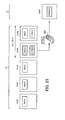
- FIG. 22 illustrates a first example of transmission and reception of extended broadcast information.
- the base station 100 or the relay station 200 performs control in such a manner as to allow LTE mobile stations to use CC#1 to CC#3 and allow LTE-A mobile stations to use CC#4 and CC#5.
- the base station 100 or the relay station 200 provides the PBCH and the E-PBCH for each of CC#1 to CC#5.
- broadcast information including information to be used for setting up a connection to the CC is transmitted.
- the broadcast information transmitted through the PBCH may be different among CCs.
- extended broadcast information which includes information indicating the relationship between CC#1 to CC#5 and types of mobile stations is transmitted.
- the extended broadcast information transmitted through the E-PBCH may be the same among all the CCs.
- the mobile station 300 which is an LTE-A mobile station receives the extended broadcast information transmitted through the E-PBCH of one of CC#1 to CC#5. From the received extended broadcast information, the mobile station 300 recognizes that CC#4 and CC#5 are available for LTE-A mobile stations. Subsequently, the mobile station 300 selects one of CC#4 and CC#5 as a CC to be used for random access. The mobile station 300 may make a selection between CC#4 and CC#5 based on results of the received power measurements. According to the example of FIG. 22 , the mobile station 300 selects CC#4 by referring to the extended broadcast information broadcast in CC#4.
- the mobile station 300 After selecting CC#4 as a CC for random access, the mobile station 300 refers to the broadcast information transmitted through the PBCH of CC#4 and transmits a random access preamble through the PRACH provided in the UL radio frame of CC#4. This starts a random access procedure between the base station 100 or the relay station 200 and the mobile station 300.
- the E-PBCH is provided for each of all the CCs, and therefore, the mobile station 300 is able to recognize CCs available for LTE-A mobile stations by referring to one arbitrary CC.
- the mobile station 300 since being an LTE-A mobile station, the mobile station 300 is able to use CC#4 and CC#5 in aggregation for data transmission and reception. In that case also, the mobile station 300 performs the random access procedures by, first, using one CC (CCs#4). Subsequently, once a connection between the base station 100 or the relay station 200 and the mobile station 300 is established, the mobile station 300 is able to use another CC (CC#5) available for LTE-A mobile stations under the control of the base station 100 or the relay station 200.
- the base station 100 or the relay station 200 may dynamically change, among CC#1 to CC#5, CCs available for LTE-A mobile stations according to the communication situation. In that case, the base station 100 or the relay station 200 dynamically changes contents of the extended broadcast information which is transmitted through the E-PBCH.
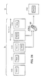
- FIG. 23 illustrates a second example of transmission and reception of the extended broadcast information.
- the base station 100 or the relay station 200 provides the PBCH for each of CC#1 to CC#5 and provides the E-PBCH only for CC#4 and CC#5, which are available for LTE-A mobile stations.
- the PBCH of each CC broadcast information including information to be used for setting up a connection to the CC is transmitted.
- E-PBCH of CC#4 and CC#5 extended broadcast information which includes information indicating the relationship between CC#1 to CC#5 and types of mobile stations is transmitted.
- the mobile station 300 which is an LTE-A mobile station receives the extended broadcast information transmitted through the E-PBCH of one of CC#4 and CC#5. From the received extended broadcast information, the mobile station 300 recognizes that CC#4 and CC#5 are available for LTE-A mobile stations. Subsequently, the mobile station 300 selects one of CC#4 and CC#5 as a CC to be used for random access.
- the E-PBCH is provided only for CCs available for LTE-A mobile stations.
- the mobile station 300 is able to determine that CCs in which the E-PBCH is detected are available for LTE-A mobile stations. In that case, the extended broadcast information transmitted through the E-PBCH of CC#4 and CC#5 does not have to include information regarding other CCs.
- the base station 100 or the relay station 200 may provide the E-PBCH for only one of CC#4 and CC#5. That is, the E-PBCH may be provided for at least one of CCs available for LTE-A mobile stations.
- a CC in which the E-PBCH is provided may be referred to as a primary CC or a primary band, and other CCs may be referred to as extended CCs or extended bands.
- FIG. 24 illustrates a third example of transmission and reception of the extended broadcast information.
- the base station 100 or the relay station 200 provides the PBCH for each of CC#1 to CC#5 and provides the E-PBCH only for CC#3 which is located in the center of CC#1 to CC#5 on the frequency axis.
- broadcast information including information to be used for setting up a connection to the CC is transmitted.
- E-PBCH extended broadcast information which includes information indicating the relationship between CC#1 to CC#5 and types of mobile stations is transmitted.
- the mobile station 300 which is an LTE-A mobile station receives the extended broadcast information transmitted through the E-PBCH of CC#3. From the received extended broadcast information, the mobile station 300 recognizes that CC#4 and CC#5 are available for LTE-A mobile stations. Subsequently, the mobile station 300 selects one of CC#4 and CC#5 as a CC to be used for random access.
- the E-PBCH is provided only for a predetermined CC.
- the mobile station 300 needs to refer only to the predetermined CC (for example, a CC located in the center of CC#1 to CC#5 on the frequency axis). Accordingly, this simplifies the processing of the mobile station 300 and reduces the processing load of the mobile station 300.
- the base station 100 and the relay station 200 are able to control connection-allowed CCs according to types of mobile stations. Therefore, this facilitates scheduling in an environment where both LTE-A mobile stations and LTE mobile stations are present. In addition, this enables easy allocation of broadband wireless resources to LTE-A mobile stations.
- an LTE-A mobile station is able to recognize available CCs before setting up a connection to the base station 100 or the relay station 200. Accordingly, even in the case where connection-available CCs are limited according to the types of mobile stations, the connection process is performed smoothly.
- the LTE-A mobile station is able to narrow down CCs for the received power measurements carried out at the time of the cell selection and CC selection, which reduces the processing load. In addition, the processing time for the cell selection (including a handover period) can be shortened.
- an LTE-A mobile station has detected three neighboring cells and, in each cell, two out of five CCs have been allocated to LTE-A mobile stations.
- received power needs to be measured for 15 CCs, which is obtained by multiplying 5 CCs by 3 neighboring cells.
- received power needs to be measured only for 6 CCs, which is obtained by multiplying 2 CCs by 3 neighboring cells. That is, the processing of the LTE-A mobile station is reduced to about two-fifth.
- the extended broadcast channel may be used to transmit not only the information indicating the correspondence between multiple CCs and types of mobile stations but also various information required to be broadcast to LTE-A mobile stations.
- a new broadcast channel not defined in the LTE may be referred to as a name other than the "extended broadcast channel".
- one of the conventional broadcast channel and the extended broadcast channel may be referred to as a first broadcast channel, and the other may be referred to as a second broadcast channel.
Landscapes
- Engineering & Computer Science (AREA)
- Computer Networks & Wireless Communication (AREA)
- Signal Processing (AREA)
- Computer Security & Cryptography (AREA)
- Mobile Radio Communication Systems (AREA)
Priority Applications (1)
| Application Number | Priority Date | Filing Date | Title |
|---|---|---|---|
| EP14167434.1A EP2816843A3 (de) | 2010-01-12 | 2010-01-12 | Mobiles Kommunikationssystem, drahtlose Kommunikationsvorrichtung, mobile Kommunikationsvorrichtung und drahtloses Kommunikationsverfahren |
Applications Claiming Priority (3)
| Application Number | Priority Date | Filing Date | Title |
|---|---|---|---|
| EP14167434.1A EP2816843A3 (de) | 2010-01-12 | 2010-01-12 | Mobiles Kommunikationssystem, drahtlose Kommunikationsvorrichtung, mobile Kommunikationsvorrichtung und drahtloses Kommunikationsverfahren |
| EP10843014.1A EP2525608B1 (de) | 2010-01-12 | 2010-01-12 | Mobiles kommunikationssystem, drahtlose kommunikationsvorrichtung, mobile kommunikationsvorrichtung und drahtloses kommunikationsverfahren |
| PCT/JP2010/050192 WO2011086655A1 (ja) | 2010-01-12 | 2010-01-12 | 移動通信システム、無線通信装置、移動通信装置および無線通信方法 |
Related Parent Applications (2)
| Application Number | Title | Priority Date | Filing Date |
|---|---|---|---|
| EP10843014.1A Division-Into EP2525608B1 (de) | 2010-01-12 | 2010-01-12 | Mobiles kommunikationssystem, drahtlose kommunikationsvorrichtung, mobile kommunikationsvorrichtung und drahtloses kommunikationsverfahren |
| EP10843014.1A Division EP2525608B1 (de) | 2010-01-12 | 2010-01-12 | Mobiles kommunikationssystem, drahtlose kommunikationsvorrichtung, mobile kommunikationsvorrichtung und drahtloses kommunikationsverfahren |
Publications (2)
| Publication Number | Publication Date |
|---|---|
| EP2816843A2 true EP2816843A2 (de) | 2014-12-24 |
| EP2816843A3 EP2816843A3 (de) | 2015-01-07 |
Family
ID=44303961
Family Applications (2)
| Application Number | Title | Priority Date | Filing Date |
|---|---|---|---|
| EP14167434.1A Withdrawn EP2816843A3 (de) | 2010-01-12 | 2010-01-12 | Mobiles Kommunikationssystem, drahtlose Kommunikationsvorrichtung, mobile Kommunikationsvorrichtung und drahtloses Kommunikationsverfahren |
| EP10843014.1A Not-in-force EP2525608B1 (de) | 2010-01-12 | 2010-01-12 | Mobiles kommunikationssystem, drahtlose kommunikationsvorrichtung, mobile kommunikationsvorrichtung und drahtloses kommunikationsverfahren |
Family Applications After (1)
| Application Number | Title | Priority Date | Filing Date |
|---|---|---|---|
| EP10843014.1A Not-in-force EP2525608B1 (de) | 2010-01-12 | 2010-01-12 | Mobiles kommunikationssystem, drahtlose kommunikationsvorrichtung, mobile kommunikationsvorrichtung und drahtloses kommunikationsverfahren |
Country Status (6)
| Country | Link |
|---|---|
| US (2) | US8855660B2 (de) |
| EP (2) | EP2816843A3 (de) |
| JP (1) | JP5687635B2 (de) |
| KR (2) | KR101395493B1 (de) |
| CN (1) | CN102696262A (de) |
| WO (1) | WO2011086655A1 (de) |
Families Citing this family (12)
| Publication number | Priority date | Publication date | Assignee | Title |
|---|---|---|---|---|
| KR20120069174A (ko) * | 2010-12-20 | 2012-06-28 | 삼성전자주식회사 | 무선통신시스템에서 임의 접근 신호 수신 장치 및 방법 |
| KR101781864B1 (ko) * | 2011-04-13 | 2017-09-26 | 엘지전자 주식회사 | 무선 접속 시스템에서 랜덤 억세스 성공률을 높이기 위한 셀 재선택 방법 |
| TWI452922B (zh) * | 2011-04-18 | 2014-09-11 | Innovative Sonic Corp | 在無線通訊系統中避免無線存取網路過載的方法和裝置 |
| JP5329598B2 (ja) * | 2011-04-20 | 2013-10-30 | シャープ株式会社 | 通信システム、移動局装置、基地局装置、ランダムアクセス処理方法及び集積回路 |
| CN109327822B (zh) | 2012-10-05 | 2022-10-25 | 交互数字专利控股公司 | 增强机器类型通信(mtc)设备覆盖的方法和装置 |
| CN104704903A (zh) * | 2012-11-09 | 2015-06-10 | 富士通株式会社 | 信息配置方法、信息发送方法、检测方法及其装置、系统 |
| US10178703B2 (en) * | 2013-05-09 | 2019-01-08 | Blackberry Limited | Stopping a random access procedure |
| CN105393618B (zh) | 2013-05-15 | 2019-11-29 | 华为技术有限公司 | 信号传输方法、装置、通信系统、终端和基站 |
| WO2017069669A1 (en) * | 2015-10-21 | 2017-04-27 | Telefonaktiebolaget Lm Ericsson (Publ) | Optimized broadcasting of system information messages |
| EP4187832A1 (de) * | 2016-01-29 | 2023-05-31 | Ntt Docomo, Inc. | Benutzerendgerät, funkbasisstation und funkkommunikationsverfahren |
| ES3009085T3 (en) * | 2017-12-20 | 2025-03-26 | Beijing Xiaomi Mobile Software Co Ltd | Method and device for extending pbch |
| CN109076321B (zh) * | 2018-07-26 | 2021-11-09 | 北京小米移动软件有限公司 | 车联网设备之间的系统信息传输方法、装置及系统 |
Citations (1)
| Publication number | Priority date | Publication date | Assignee | Title |
|---|---|---|---|---|
| JP2009218813A (ja) | 2008-03-10 | 2009-09-24 | Mitsubishi Electric Corp | 通信システムおよび基地局 |
Family Cites Families (30)
| Publication number | Priority date | Publication date | Assignee | Title |
|---|---|---|---|---|
| US6128490A (en) | 1997-05-08 | 2000-10-03 | Nortel Networks Limited | Wireless communication system that supports selection of operation from multiple frequency bands and multiple protocols and method of operation therefor |
| US6600917B1 (en) | 1999-10-04 | 2003-07-29 | Telefonaktiebolaget Lm Ericsson (Publ) | Telecommunications network broadcasting of service capabilities |
| JP4841235B2 (ja) * | 2005-11-30 | 2011-12-21 | 富士通株式会社 | 無線基地局、無線通信方法及び無線通信システム |
| BRPI0711181A2 (pt) | 2006-05-01 | 2011-08-23 | Ntt Docomo Inc | estação móvel, estação de base, e método de controle de comunicação |
| EP2206396B1 (de) * | 2007-10-31 | 2017-07-19 | Koninklijke Philips N.V. | Verfahren zur signalisierung von direktzugriffskanälen |
| US8340014B2 (en) * | 2007-12-26 | 2012-12-25 | Lg Electronics Inc. | Method for transmitting and receiving signals using multi-band radio frequencies |
| US8300555B2 (en) | 2008-01-30 | 2012-10-30 | Qualcomm Incorporated | Management of wireless relay nodes using identifiers |
| WO2009116751A2 (en) * | 2008-03-16 | 2009-09-24 | Lg Electronics Inc. | Method and apparatus for acquiring resource allocation of control channel |
| US8711811B2 (en) | 2008-06-19 | 2014-04-29 | Telefonaktiebolaget L M Ericsson (Publ) | Identifying multi-component carrier cells |
| CN102067493A (zh) | 2008-06-23 | 2011-05-18 | 松下电器产业株式会社 | 参照信号配置方法和无线通信基站装置 |
| CN101616438A (zh) | 2008-06-24 | 2009-12-30 | 华为技术有限公司 | 多载波系统信号发射、接收方法及装置 |
| US8325661B2 (en) * | 2008-08-28 | 2012-12-04 | Qualcomm Incorporated | Supporting multiple access technologies in a wireless environment |
| US8842617B2 (en) * | 2008-10-01 | 2014-09-23 | Lg Electronics Inc. | Method and device for wireless subframe resource allocation |
| EP2200361A1 (de) * | 2008-10-07 | 2010-06-23 | Nokia Siemens Networks OY | Zellulares drahtloses Netzwerk mit adaptiver Strahlbildung für verschiedene Funkabdeckungsbereiche für Kontroll- und Datakanälen |
| AR073832A1 (es) * | 2008-10-20 | 2010-12-01 | Interdigital Patent Holdings | Senalizacion y adquisicion de canal de control para agregar onda portadora |
| CN101730115B (zh) * | 2008-10-24 | 2013-01-30 | 华为技术有限公司 | 中继传输的方法及设备 |
| US20100113041A1 (en) * | 2008-10-31 | 2010-05-06 | Maik Bienas | Method of signalling system information, method of receiving system information, radio base station and radio communication terminal |
| JP5069670B2 (ja) * | 2008-10-31 | 2012-11-07 | 株式会社エヌ・ティ・ティ・ドコモ | 移動通信システム |
| CN101771951B (zh) * | 2009-01-06 | 2014-08-06 | 电信科学技术研究院 | 一种广播信息传输方法及装置 |
| JP5648286B2 (ja) * | 2009-01-14 | 2015-01-07 | ソニー株式会社 | 通信システム、通信装置、プログラム、及び通信制御方法 |
| US8804631B2 (en) * | 2009-03-02 | 2014-08-12 | Mediatek Inc. | Method and apparatus for communicating carrier configuration in multi-carrier OFDM systems |
| KR101349842B1 (ko) * | 2009-04-13 | 2014-01-10 | 엘지전자 주식회사 | 개선 시스템을 지원하는 기지국에서의 시스템 정보 전송 방법 및 장치 |
| KR101337093B1 (ko) * | 2009-06-15 | 2013-12-06 | 후지쯔 가부시끼가이샤 | 무선 통신 시스템, 기지국 장치, 단말기 장치, 및 무선 통신 시스템에서의 무선 통신 방법 |
| US8825066B2 (en) * | 2009-06-16 | 2014-09-02 | Nokia Corporation | Apparatus and method for interworking between multiple frequency band modes |
| US8559950B2 (en) * | 2010-02-01 | 2013-10-15 | Intel Mobile Communications GmbH | Radio base stations, radio communication devices, methods for controlling a radio base station, and methods for controlling a radio communication device |
| JPWO2011099135A1 (ja) * | 2010-02-12 | 2013-06-13 | 富士通株式会社 | 移動通信システム、基地局、移動局および無線通信方法 |
| WO2011121714A1 (ja) * | 2010-03-30 | 2011-10-06 | 富士通株式会社 | 移動通信システム、無線中継装置、移動通信装置および無線通信方法 |
| US8340004B2 (en) * | 2010-04-07 | 2012-12-25 | Qualcomm Incorporated | Combining transmission with incrementing fields |
| GB2486926B (en) * | 2011-06-02 | 2013-10-23 | Renesas Mobile Corp | Frequency hopping in license-exempt/shared bands |
| KR101587144B1 (ko) * | 2011-09-29 | 2016-01-20 | 노키아 솔루션스 앤드 네트웍스 오와이 | 간섭 관리를 위한 방법 및 장치 |
-
2010
- 2010-01-12 EP EP14167434.1A patent/EP2816843A3/de not_active Withdrawn
- 2010-01-12 WO PCT/JP2010/050192 patent/WO2011086655A1/ja not_active Ceased
- 2010-01-12 KR KR1020127017318A patent/KR101395493B1/ko not_active Expired - Fee Related
- 2010-01-12 CN CN2010800610036A patent/CN102696262A/zh active Pending
- 2010-01-12 EP EP10843014.1A patent/EP2525608B1/de not_active Not-in-force
- 2010-01-12 KR KR1020137034579A patent/KR101570596B1/ko not_active Expired - Fee Related
- 2010-01-12 JP JP2011549794A patent/JP5687635B2/ja not_active Expired - Fee Related
-
2012
- 2012-06-29 US US13/537,932 patent/US8855660B2/en not_active Expired - Fee Related
-
2013
- 2013-06-12 US US13/916,144 patent/US20130272249A1/en not_active Abandoned
Patent Citations (1)
| Publication number | Priority date | Publication date | Assignee | Title |
|---|---|---|---|---|
| JP2009218813A (ja) | 2008-03-10 | 2009-09-24 | Mitsubishi Electric Corp | 通信システムおよび基地局 |
Non-Patent Citations (2)
| Title |
|---|
| "Evolved Universal Terrestrial Radio Access (E-UTRA) Radio Resource Control (RRC); Protocol specification", 3GPP (3RD GENERATION PARTNERSHIP PROJECT, September 2009 (2009-09-01) |
| "Feasibility study for Further Advancements for E-UTRA (LTE-Advanced", 3GPP (3RD GENERATION PARTNERSHIP PROJECT, September 2009 (2009-09-01) |
Also Published As
| Publication number | Publication date |
|---|---|
| US8855660B2 (en) | 2014-10-07 |
| EP2525608B1 (de) | 2017-05-24 |
| US20120270540A1 (en) | 2012-10-25 |
| EP2816843A3 (de) | 2015-01-07 |
| CN102696262A (zh) | 2012-09-26 |
| KR101570596B1 (ko) | 2015-11-19 |
| JP5687635B2 (ja) | 2015-03-18 |
| WO2011086655A1 (ja) | 2011-07-21 |
| JPWO2011086655A1 (ja) | 2013-05-16 |
| US20130272249A1 (en) | 2013-10-17 |
| EP2525608A4 (de) | 2013-12-25 |
| KR20140021038A (ko) | 2014-02-19 |
| KR20120102741A (ko) | 2012-09-18 |
| KR101395493B1 (ko) | 2014-05-14 |
| EP2525608A1 (de) | 2012-11-21 |
Similar Documents
| Publication | Publication Date | Title |
|---|---|---|
| EP2525608B1 (de) | Mobiles kommunikationssystem, drahtlose kommunikationsvorrichtung, mobile kommunikationsvorrichtung und drahtloses kommunikationsverfahren | |
| US10863499B2 (en) | Method for transmitting or receiving signal in wireless communication system and device for performing the method | |
| EP2408247B1 (de) | Verfahren zur betriebsmittelverteilung, verfahren zur datenübertragung, basisstation und endgerät | |
| CN108496387B (zh) | 基站装置、终端装置以及通信方法 | |
| JP2022528809A (ja) | 無線通信システムにおいて共有チャネルを送受信する方法及びそのための装置 | |
| CN108496388B (zh) | 基站装置、终端装置以及通信方法 | |
| US11997549B2 (en) | Blind decoding limits for dual active protocol stack (DAPS) handover | |
| KR20200041943A (ko) | 무선 통신시스템에서 상향링크 전송 및 하향링크 수신방법, 장치 및 시스템 | |
| CN118432787A (zh) | 无线通信系统的信道复用方法和复用的信道传输方法及使用该方法的设备 | |
| US9673873B2 (en) | Mobile communications system, base station, mobile station, and wireless communication method | |
| WO2013029946A1 (en) | Search space reconfiguration for enhanced-pdcch | |
| CN107535001A (zh) | 用户终端、无线基站以及无线通信方法 | |
| KR20200082035A (ko) | 무선 통신시스템에서 pucch 전송 방법, 장치 및 시스템 | |
| KR20180108342A (ko) | 무선 통신시스템의 제어채널의 전송 및 수신방법, 장치 및 시스템 | |
| US20120269152A1 (en) | Method for configuring a resource, method for transceiving data in the configured resource, and apparatus for same in a wireless communication system | |
| JP5794267B2 (ja) | 無線通信システム、端末装置、基地局および無線通信方法 | |
| JP5729492B2 (ja) | 移動通信システム、無線通信装置、移動通信装置および無線通信方法 | |
| TWI538457B (zh) | A wireless communication system, a terminal device, a base station device, and a wireless communication method | |
| TWI426750B (zh) | 移動通訊系統、無線通訊裝置、移動通訊裝置及無線通訊方法 | |
| KR20180082061A (ko) | 제어채널의 전송 및 수신방법, 장치 및 시스템 | |
| CN120435906A (zh) | 用于在无线通信系统中接收下行链路数据的设备和方法 | |
| CN105592521A (zh) | 无线通信装置、无线终端装置以及无线通信方法 |
Legal Events
| Date | Code | Title | Description |
|---|---|---|---|
| PUAL | Search report despatched |
Free format text: ORIGINAL CODE: 0009013 |
|
| PUAI | Public reference made under article 153(3) epc to a published international application that has entered the european phase |
Free format text: ORIGINAL CODE: 0009012 |
|
| 17P | Request for examination filed |
Effective date: 20140507 |
|
| AC | Divisional application: reference to earlier application |
Ref document number: 2525608 Country of ref document: EP Kind code of ref document: P |
|
| AK | Designated contracting states |
Kind code of ref document: A2 Designated state(s): AT BE BG CH CY CZ DE DK EE ES FI FR GB GR HR HU IE IS IT LI LT LU LV MC MK MT NL NO PL PT RO SE SI SK SM TR |
|
| AK | Designated contracting states |
Kind code of ref document: A3 Designated state(s): AT BE BG CH CY CZ DE DK EE ES FI FR GB GR HR HU IE IS IT LI LT LU LV MC MK MT NL NO PL PT RO SE SI SK SM TR |
|
| RIC1 | Information provided on ipc code assigned before grant |
Ipc: H04W 88/10 20090101ALI20141128BHEP Ipc: H04W 48/10 20090101AFI20141128BHEP Ipc: H04W 48/12 20090101ALI20141128BHEP |
|
| R17P | Request for examination filed (corrected) |
Effective date: 20150323 |
|
| RBV | Designated contracting states (corrected) |
Designated state(s): AT BE BG CH CY CZ DE DK EE ES FI FR GB GR HR HU IE IS IT LI LT LU LV MC MK MT NL NO PL PT RO SE SI SK SM TR |
|
| 17Q | First examination report despatched |
Effective date: 20180111 |
|
| STAA | Information on the status of an ep patent application or granted ep patent |
Free format text: STATUS: THE APPLICATION HAS BEEN WITHDRAWN |
|
| 18W | Application withdrawn |
Effective date: 20180416 |