EP2818337A1 - Véhicule agricole - Google Patents
Véhicule agricole Download PDFInfo
- Publication number
- EP2818337A1 EP2818337A1 EP20140170154 EP14170154A EP2818337A1 EP 2818337 A1 EP2818337 A1 EP 2818337A1 EP 20140170154 EP20140170154 EP 20140170154 EP 14170154 A EP14170154 A EP 14170154A EP 2818337 A1 EP2818337 A1 EP 2818337A1
- Authority
- EP
- European Patent Office
- Prior art keywords
- control unit
- tire pressure
- vehicle
- operable
- tire
- Prior art date
- Legal status (The legal status is an assumption and is not a legal conclusion. Google has not performed a legal analysis and makes no representation as to the accuracy of the status listed.)
- Granted
Links
Images


Classifications
-
- B—PERFORMING OPERATIONS; TRANSPORTING
- B60—VEHICLES IN GENERAL
- B60C—VEHICLE TYRES; TYRE INFLATION; TYRE CHANGING; CONNECTING VALVES TO INFLATABLE ELASTIC BODIES IN GENERAL; DEVICES OR ARRANGEMENTS RELATED TO TYRES
- B60C23/00—Devices for measuring, signalling, controlling, or distributing tyre pressure or temperature, specially adapted for mounting on vehicles; Arrangement of tyre inflating devices on vehicles, e.g. of pumps or of tanks; Tyre cooling arrangements
- B60C23/001—Devices for manually or automatically controlling or distributing tyre pressure whilst the vehicle is moving
- B60C23/002—Devices for manually or automatically controlling or distributing tyre pressure whilst the vehicle is moving by monitoring conditions other than tyre pressure or deformation
-
- B—PERFORMING OPERATIONS; TRANSPORTING
- B60—VEHICLES IN GENERAL
- B60C—VEHICLE TYRES; TYRE INFLATION; TYRE CHANGING; CONNECTING VALVES TO INFLATABLE ELASTIC BODIES IN GENERAL; DEVICES OR ARRANGEMENTS RELATED TO TYRES
- B60C23/00—Devices for measuring, signalling, controlling, or distributing tyre pressure or temperature, specially adapted for mounting on vehicles; Arrangement of tyre inflating devices on vehicles, e.g. of pumps or of tanks; Tyre cooling arrangements
-
- A—HUMAN NECESSITIES
- A01—AGRICULTURE; FORESTRY; ANIMAL HUSBANDRY; HUNTING; TRAPPING; FISHING
- A01B—SOIL WORKING IN AGRICULTURE OR FORESTRY; PARTS, DETAILS, OR ACCESSORIES OF AGRICULTURAL MACHINES OR IMPLEMENTS, IN GENERAL
- A01B63/00—Lifting or adjusting devices or arrangements for agricultural machines or implements
- A01B63/02—Lifting or adjusting devices or arrangements for agricultural machines or implements for implements mounted on tractors
- A01B63/10—Lifting or adjusting devices or arrangements for agricultural machines or implements for implements mounted on tractors operated by hydraulic or pneumatic means
- A01B63/111—Lifting or adjusting devices or arrangements for agricultural machines or implements for implements mounted on tractors operated by hydraulic or pneumatic means regulating working depth of implements
- A01B63/112—Lifting or adjusting devices or arrangements for agricultural machines or implements for implements mounted on tractors operated by hydraulic or pneumatic means regulating working depth of implements to control draught load, i.e. tractive force
Definitions
- the invention relates to an agricultural vehicle having a tire pressure filling system and an electronic control unit for adjusting the tire pressure of the vehicle as a function of sensory operating parameters of the vehicle according to the preamble of claim 1.
- Agricultural vehicles such as tractors, combine harvesters, forage harvesters, and the like are known in the art, which are equipped with various types of tire pressure fillers to allow the operator to set a desired tire pressure. Because, as is known, agricultural vehicles can be adapted to the respective application by selecting a suitable tire pressure. For example, tractors are operated in the field with a lower tire pressure than when driving on the road in order to keep the ground stress and thus soil compaction low when driving through an increased footprint (relatively lower tire pressure). On the other hand, when driving on the road (relatively higher tire pressure) considerable fuel is saved by a lower rolling resistance of the tire / ground pairing.
- tire pressure in the context of this description refers to the "internal tire pressure" prevailing inside a tire.
- tire load limit refers to the minimum permissible tire pressure which is permissible for a specific wheel load and driving speed of the vehicle.
- a preferred tire pressure to be selected for a specific application situation not only depends on boundary conditions such as driving speed and wheel load, but also depends in particular on which target should actually be tracked with the adaptation of the tire pressure. Even for experienced vehicle operators, it may be difficult to choose a tire pressure, which in addition to fulfillment of external boundary conditions also represents a particularly suitable setting, for example for achieving the lowest possible fuel consumption or the highest possible area performance.
- control unit is operable in different, selectable by an operator operating modes, wherein by selecting one of the operating modes, the tire pressure in consideration of this operating mode assigned Control strategy is regulated.
- agricultural vehicles are in practice operated with different strategic objectives of the respective work input. For example, it may be desirable to achieve the lowest possible stress (in particular: compaction) of the soil during a field trip in order to protect it. Alternatively, it may be desirable to perform a work assignment with the highest possible efficiency (meaning: lowest possible fuel consumption). Again, alternatively, it may be desirable to provide the highest possible driving force in a work application, for example, to achieve a high area performance. It has also been recognized that under certain circumstances the tire pressure for minimum soil compaction differs from the tire pressure for maximum efficiency during traction work in the field. On the other hand, for minimum soil compaction, although in principle the lowest permissible pressure due to the tire load capacity to choose, but this is not necessarily the optimum for maximum efficiency or driving power of the vehicle.
- the control unit of the vehicle according to the invention can be operated by operator selection in different operating modes. Depending on the selected operating mode, the control unit then regulates the tire pressure according to the control strategy assigned to this operating mode.
- the control unit then regulates the tire pressure according to the control strategy assigned to this operating mode.
- various operating modes that can be selected by the operator are conceivable in order to execute the respectively associated control strategies.
- the selection could advantageously take place via an operator interface, such as, for example, a user interface arranged in a driver's cab of the vehicle.
- control unit is operable in an operating mode in which the control unit regulates the tire pressure with the aim of high efficiency of the vehicle.
- a control strategy serves to work with the vehicle energy-efficient, especially fuel-efficient.
- the vehicle has means for detecting a suspension efficiency and a traction coefficient, wherein the control unit is operable in the context of a process for increasing efficiency, taking into account the tire load limit to set a tire pressure for which a maximum suspension efficiency above the traction coefficient results.
- the control unit is operable in the context of a process for increasing efficiency, taking into account the tire load limit to set a tire pressure for which a maximum suspension efficiency above the traction coefficient results.
- the chassis efficiency corresponds to the ratio of Radzugiere over mechanical input power of the wheel.
- the chassis efficiency can also be calculated with the axle-related variables axle train power and mechanical input power in the axle or the total vehicle related quantities total train power of the vehicle and mechanical input power of the chassis.
- the traction coefficient corresponds to the ratio of wheel drive force to wheel load.
- the traction coefficient can also be calculated using the axle-related variables axle load force and axle load or the vehicle-related vehicle pulling force and total vehicle weight values for the vehicle as a whole.
- the vehicle is equipped with suitable sensors.
- sensors for detecting tire pressure, wheel speed, wheel torque, wheel load, wheel drive force and vehicle speed.
- sensors which are related to the axle or to the entire vehicle, i. E. Sensors for detecting axle speed or transmission output speed, axle torque or transmission output torque, axle load or total load, axle load force or total tractive force of the vehicle.
- control unit is advantageously operable to lower the tire pressure initially, in particular as far as a tire load limit, as part of the process for increasing efficiency, in order subsequently to set the tire pressure for which maximum chassis efficiency is measured.
- control unit can preferably set the tire pressure for which the maximum chassis efficiency is reached before the complete lowering to the tire load limit, in order to achieve a faster adaptation to achieve.
- the tire pressure for which the maximum chassis efficiency is achieved does not necessarily have to be the minimum tire pressure due to the tire load capacity.
- the chassis efficiency is determined continuously while the control unit is based on a mean value formed.
- control unit is operable, by specifying a driving speed, the vehicle in an operating point with maximum suspension efficiency to operate.
- a driving speed the vehicle in an operating point with maximum suspension efficiency to operate.
- Such an operation is possible because the course of the suspension efficiency above the traction coefficient due to variations during field work (varying working depth of implements, varying soil strength) is at least partially known.
- the control unit can thus shift the operating point by varying the driving speed, so that it lies in the range of the maximum suspension efficiency. In this case, a reduction in the operating speed leads to a decrease in the required tractive force and thus the traction coefficient, while an increase in the operating speed causes an increase in traction and traction coefficient.
- Such a specification of a driving speed can generally take the form of a recommendation to the operator and / or in the form of a direct intervention in the driving controller of the vehicle.
- the specification of a driving speed could refer to an operating point with a definable distance to the maximum suspension efficiency, whereby a compromise between efficiency and area performance would be achieved.
- the control unit determines whether it makes sense to readjust the tire pressure based on changes in the position of the average suspension efficiency above the traction coefficient. Eventually, the slip associated with a suspension efficiency and traction coefficient may indicate a re-adjustment.
- control unit is operable in an operating mode in which the control unit regulates the tire pressure with the aim of high traction of the vehicle.
- control strategy is used in particular to achieve a high area performance with the vehicle.
- the vehicle has at least means for detecting a traction coefficient, wherein the control unit is operable in a process to increase traction, taking into account the tire load limit to set a tire pressure for which there is a maximum driving force for a given wheel load.
- the vehicle is equipped with suitable sensors. This includes, for example, sensors for detecting tire pressure, wheel speed, wheel torque, wheel load, wheel drive force and / or vehicle speed.
- the control unit is advantageously operable to lower the tire pressure, preferably as far as possible, to a tire-carrying capacity limit as part of a process for increasing traction in order subsequently to set the tire pressure for which a maximum driving force for a given wheel load is measured.
- control unit may preferably set the tire pressure for which the maximum traction coefficient is reached even before completely lowering the tire load limit, to achieve a faster adjustment.
- control unit is advantageously still operable to increase the driving speed of the vehicle with an increase in traction achieved.
- a speed limit for field work in which a certain operating speed may not be exceeded, there may be the possibility to set a speed limit. If the vehicle reaches this speed limit, it can be provided in a further advantageous manner that the control unit automatically changes to the previously described operating mode with the aim of high efficiency of the vehicle to work as efficiently as possible at the reached, not to be exceeded speed level.
- the control unit determines whether it makes sense to readjust the tire pressure based on changes in the position of the average suspension efficiency above the traction coefficient.
- the knowledge of the traction coefficient is necessary. It is conceivable to optimize the traction by wheel or axle individually or for the entire vehicle. In addition, it is conceivable to estimate the traction conditions of the front axle at least partially from the values of the rear axle.
- the control unit is operable in an operating mode in which the control unit regulates the tire pressure with the aim of low stress on the ground, in particular by the control unit setting a minimum tire pressure permissible on the basis of wheel load and driving speed.
- the vehicle is equipped with a corresponding sensor.
- control strategies described above relate to an automatic adjustment of the tire pressure by the control unit according to a selectable control strategy.
- the control unit can preferably be brought into a manual operating mode in which a tire pressure desired by the operator can be set freely, for example as a numerical value (for the air pressure) and thus independently of the previously described control strategies.
- one or more quick-selection buttons can be provided in this context, under which the operator can retrieve stored tire pressure values quickly and easily.
- a general speed dial for road driving and a general speed dial for field driving could be provided.
- the control unit is operable to monitor the exceeding of a tire wear limit.
- the tire load limit in this context represents a higher control limit to ensure that the load capacity of the tire, as for example specified by the manufacturer for certain speeds and wheel loads, is not exceeded.
- the monitoring of the control limit can always be carried out at any time irrespective of an operating mode selected for the tire pressure control and / or independently of the manual operating mode.
- the control device outputs a visual and / or audible indication to the operator when the tire load limit is exceeded, and / or that the control device fundamentally prevents the tire load limit from being exceeded.
- the control unit allows a brief crossing, because this may not be critical for the tire.
- a tolerated crossing of the deadweight limit in the sense of e.g. switchable emergency function be provided to free, for example, a stuck vehicle again.
- the vehicle In order to monitor the exceeding of the tire load limit, the vehicle is equipped with suitable sensors. This includes in particular sensors for detecting vehicle speed, wheel load and tire pressure of the vehicle.
- the described vehicle provides operator assistance in choosing appropriate tire pressure through electronic optimization of the tire-to-ground contact. On the one hand it is ensured that the tire load limit is not exceeded, on the other hand that an optimal tire pressure for given conditions is set in accordance with a control strategy selectable by the operator. Possible control strategies are aimed at efficiency, area performance and soil conservation. Efficiency control strategy can contribute to fuel savings by not having to set the minimum tire pressure when working on the field, but the tire pressure that will produce the highest suspension efficiency.
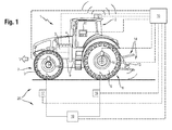
- Fig. 1 an agricultural vehicle in the form of a tractor 1 is shown schematically from the side.
- the tractor 1 travels at a vehicle speed v in the indicated direction of the arrow v over a ground (eg field ground, road).
- the tractor 1 has a drive train, which in particular comprises a drive motor 3, a transmission 4, shafts 9, two front wheels 7 and two rear wheels 8.
- the components cooperate in a manner known per se such that a drive power provided by the drive motor 3 can be transmitted to the front wheels 7 and rear wheels 8 (less any losses occurring) in order to set the tractor 1 in motion relative to the ground.
- the vehicle could be another agricultural vehicle rather than a tractor.
- the front wheels 7 and rear wheels 8 of the tractor 1 are each equipped with a front tire 5 and rear tire 6, respectively.
- the front tires 5 and rear tires 6 are connected via pressure lines (including rotary unions not shown here) with a pneumatic device 19, which includes all the pneumatic components that are necessary for filling the tires 5, 6 with compressed air (compressor, electromagnetic valve and / or Switching devices etc.).
- a pneumatic device 19 which includes all the pneumatic components that are necessary for filling the tires 5, 6 with compressed air (compressor, electromagnetic valve and / or Switching devices etc.).
- the tire pressure filling system 20 allows filling and also bleeding the tires 5, 6 of the tractor 1 while driving.
- Tire pressure filling systems with such functionality are known to those skilled in the art in different versions and need not be further explained here.
- the tractor 1 is further equipped with an electronic control unit 10.
- the electronic control unit 10 is connected to a control and display device 11 arranged in a driver's cab 2 of the tractor 1.
- various information provided by the control unit 10 can be called up and displayed.
- the operator can make settings via the operating and display device 11 which enter the control unit 10 as input signals. The possibilities arising from this will be explained below.
- the control unit 10 is further connected to a comprehensive sensor system. Pressure sensors 17 and 18 transmit the control unit 10, the tire pressure in the front and rear tires 5, 6. Furthermore, the rear wheel 8 is associated with a sensor assembly 16 which is connected to the control unit 10. With the sensor arrangement 16, various operating parameters relating to the rear wheel 8, such as its rotational speed, torque, wheel load and wheel drive force, can be detected. For a structural design to the individual required sensors various known per se options are conceivable (not shown in the drawing). This could - assuming appropriate conversion - instead of the detection of the wheel speed, a detection of the axle speed and / or the transmission output speed, if this appears constructive cheaper. Similarly, with appropriate conversion instead of the wheel torque, the axle torque and / or the transmission output torque could be sensed.
- the axle load and / or total load of the tractor 1 could be detected.
- the wheel drive force Achstriebkraft and / or the total traction of the tractor 1 could be detected.
- the front wheel 7 is associated with a sensor assembly 15 which is connected to the control unit 10.
- the sensor arrangement 15 has the same functionality As the sensor assembly 16, so serves to detect the speed, torque, wheel load and Radretekraft the front wheel 7.
- the sensor assembly 15 may be structurally designed differently. For this purpose, reference is made to the previous statements with regard to the sensor arrangement 16.
- control unit 10 is connected to a sensor system for detecting the speed v of the tractor 1.
- the tractor 1 is equipped according to the embodiment shown for this purpose with two speed detection system.
- a radar sensor 13 is arranged, which determines the driving speed v of the tractor 1 by scanning the soil and transmitted to the control unit 10.
- a navigation device 12 is arranged on the driver's cab 2, which determines the driving speed v of the tractor 1 using satellite-supported position determination (for example GPS) and transmits it to the control unit 10. It may be sufficient that the tractor 1 is equipped with one of the described possibilities of speed determination.
- the tire pressure in the front and rear tires 5, 6 can be controlled in the following manner.
- An operator of the tractor 1 is on the control and display device 11 with the control unit 10 in dialogue.
- the operator can operate the control unit 10 in various operating modes by selecting options.
- the result of selecting an operating mode is that the control unit 10 will then regulate the tire pressure taking into account a control strategy assigned to this operating mode.
- Fig. 2 which shows a preferred selection structure.
- the operator has the option to choose between three different control strategies (efficiency, traction, soil protection), which corresponds to operation of the control unit 10 in three different modes of operation.
- control unit 10 will automatically regulate the tire pressure of the tractor 1 taking into account a set objective in this control strategy and to determine a suitable tire pressure for the tires 5, 6, taking into account the available sensor signals and this by controlling the adjust pneumatic device 19. After selecting the control strategy, the operator is thus relieved of the further monitoring or adjustment of the tire pressure.
- the operator has the option of switching the control unit 10 into a manual mode.
- manual mode the operator can set a tire pressure freely.
- the control unit 10 ensures that the desired tire pressure is set in the tires 5, 6.
- the control unit 10 carries out a monitoring which includes an ongoing control of exceeding the tire load limit, ie the minimum permissible tire pressure, which for a given wheel load and Driving speed of the vehicle is still allowed. This is preferably done in such a way that upon activation of one of the three control strategies exceeding the tire wear limit is completely prevented by the control unit 10, if necessary, automatically brings the tire pressure to a sufficient level.
- the monitoring takes place in such a way that the operator is visually and possibly acoustically warned when the tire load limit is exceeded via the operating and display device 11. Again, an automatic prevention by the control unit 10 would be conceivable.
- control unit 10 regulates the tire pressure with the aim that traction work of the tractor 1 (in particular on the field) is carried out with maximum efficiency, in particular with the lowest possible fuel consumption.
- suspension efficiency ratio of tractive effort of the tractor 1 relative to the mechanical input power of the chassis
- the subsequent optimization process includes at least a first, optionally also a second step:
- the optimal tire pressure is determined for the given conditions (eg wheel-specific or axle-specific). For this purpose, by driving by the control unit 10, the tire pressure on the tire load limit (depending on speed v and wheel load, detected by sensors 12, 13 and 15, 16) lowered. Subsequently, the tire pressure is set, for which a maximum suspension efficiency was measured. This does not necessarily have to be the minimum possible tire pressure due to the tire carrying capacity.
- Fig. 3 graphically depicts the operational characteristics of a tractor tire qualitatively. Plotted are the course of the suspension efficiency (continuous line), the rolling resistance (dash-dot line) and the slip (dashed line) as a function of the traction coefficient.
- An advantage of the representation is that it thus characterizes the technically particularly interesting relationships between motive power and efficiency by means of a single curve (that of the chassis efficiency).
- the traction coefficient is - assuming appropriate sensors - to a directly measurable size, since this is determined by the ratio of driving force relative to the associated wheel load. The traction coefficient can thus be determined via the sensors 15 and 16.
- the chassis efficiency is also provided with corresponding sensor technology - a directly measurable variable, since this is determined by the ratio of the tractive power of the vehicle to the mechanical input power of the chassis.
- a directly measurable variable since this is determined by the ratio of the tractive power of the vehicle to the mechanical input power of the chassis.
- the suspension efficiency is preferably determined continuously and the control unit 10 then based on the average value.
- the illustration Fig. 4 shows in a graph (representation of the suspension efficiency above the traction coefficient) the averaging of the suspension efficiency curve from individual measurement points.
- the control unit 10 by driving a driving controller (indicated by signal line from the control unit 10 to the drive motor 3 and gear 4) vary the travel speed v of the tractor 1 to an operating point P B (see Fig. 4 ) to the range of maximum landing gear efficiency.
- This "target operating point" (with maximum landing gear efficiency) is in Fig. 4 again referred to as P max .
- the course of the suspension efficiency over the traction coefficient is known in some areas, since the traction coefficient fluctuates during traction on the field, for example, by varying the working depth of an attachment and the soil strength, the operating point P B thus moves back and forth in the map.
- the control unit 10 can thus shift the operating point P B by varying the driving speed v by knowing the curve of the average suspension efficiency above the traction coefficient so that it lies in the range of the maximum suspension efficiency P max .
- a reduction in the vehicle speed v leads to a decrease in the required tractive effort and thus of the traction coefficient, while an increase in the vehicle speed v causes an increase in traction and traction coefficients.
- the control unit 10 could recommend to the operator a reduction or increase in the driving speed v with simultaneous visualization (by display means 11) of the suspension efficiency, or adjust it automatically by direct access to the driving controller.
- control unit 10 it would be conceivable for the control unit 10 to adjust the operating point to a distance defined by the operator from the maximum of the chassis efficiency, which represents a good compromise between the efficiency of the power transmission and area performance.
- control unit 10 determines the suspension efficiency and the traction coefficient.
- An optimization of the traction can be done by wheel, by axle or for the whole vehicle. It is also it is conceivable that the control unit 10 estimates the traction conditions of the front axle at least partially from the values for the rear axle.
- control unit 10 regulates the tire pressure with the aim that maximum area performance is achieved during tractive work on the field. For this purpose, the control unit 10 optimizes the tensile force for the given conditions.
- the traction coefficient explained above plays a decisive role.
- the control unit 10 determines an optimal tire pressure (for example, wheel-specific or axle-specific) for the given conditions. For this purpose, the tire pressure on the tire load capacity limit (depending on the speed v and wheel load, detected by sensors 12, 13 or 15, 16) is lowered by activation by the control unit 10. Subsequently, the tire pressure is set, for which maximum driving forces above the wheel load, i. a maximum traction coefficient). Such a traction gain can then be used to increase the vehicle speed v. For field work where a certain speed may not be exceeded, the operator has the option to set a speed limit. If the tractor 1 reaches this, the chassis efficiency is maximized in accordance with the "Efficiency" control strategy.
- the tire pressure on the tire load capacity limit depending on the speed v and wheel load, detected by sensors 12, 13 or 15, 16
- the traction coefficient is preferably determined continuously and the control unit 10 then orients itself to the mean value. Once the tire pressure has been adjusted, the control unit 10 decides on the basis of changes in the position of the average suspension efficiency over the traction coefficient, whether it makes sense to readjust the tire pressure. Eventually, the slip associated with a suspension efficiency and traction coefficient may indicate a re-adjustment.
- control unit 10 determines the suspension efficiency and the traction coefficient. An optimization of the traction can be done by wheel, by axle or for the whole vehicle. It is also it is conceivable that the control unit 10 estimates the traction conditions of the front axle at least partially from the values for the rear axle.
- control unit 10 regulates the tire pressure with the aim that work takes place in the field with minimal stress, in particular compaction of the soil.
- control unit 10 controls the pneumatic device 19 in such a way that-according to the higher-order control limit-the lowest tire pressure permissible on the basis of the wheel load and the vehicle speed v is set.
- control unit 10 takes into account the driving speed and the wheel load. An optimization can be done by wheel, by axle or for the entire vehicle. In addition, it is conceivable that the control unit 10 estimates the conditions of the front axle at least partially from the values for the rear axle.
Landscapes
- Engineering & Computer Science (AREA)
- Mechanical Engineering (AREA)
- Life Sciences & Earth Sciences (AREA)
- Soil Sciences (AREA)
- Environmental Sciences (AREA)
- Vehicle Body Suspensions (AREA)
- Arrangement And Driving Of Transmission Devices (AREA)
- Tires In General (AREA)
- Control Of Transmission Device (AREA)
Applications Claiming Priority (1)
| Application Number | Priority Date | Filing Date | Title |
|---|---|---|---|
| DE102013106548.1A DE102013106548A1 (de) | 2013-06-24 | 2013-06-24 | Landwirtschaftliches Fahrzeug |
Publications (2)
| Publication Number | Publication Date |
|---|---|
| EP2818337A1 true EP2818337A1 (fr) | 2014-12-31 |
| EP2818337B1 EP2818337B1 (fr) | 2021-05-05 |
Family
ID=50819614
Family Applications (1)
| Application Number | Title | Priority Date | Filing Date |
|---|---|---|---|
| EP14170154.0A Active EP2818337B1 (fr) | 2013-06-24 | 2014-05-28 | Véhicule agricole |
Country Status (3)
| Country | Link |
|---|---|
| EP (1) | EP2818337B1 (fr) |
| DE (1) | DE102013106548A1 (fr) |
| RU (1) | RU2667056C2 (fr) |
Cited By (6)
| Publication number | Priority date | Publication date | Assignee | Title |
|---|---|---|---|---|
| ITUB20154063A1 (it) * | 2015-10-06 | 2017-04-06 | Trelleborg Wheel Sys Italia Spa | Procedimento e dispositivo di controllo e regolazione della pressione degli pneumatici. |
| DE102016003928A1 (de) * | 2016-03-31 | 2017-10-05 | Man Truck & Bus Ag | Verfahren zur Ermittlung eines Soll-Reifendrucks bei einem Fahrzeug |
| EP3243368A2 (fr) | 2016-05-10 | 2017-11-15 | CLAAS Tractor S.A.S. | Combinaison d'appareil de véhicule de traction ayant un système d'assistance au conducteur |
| DE102016118205A1 (de) | 2016-05-10 | 2017-11-16 | Claas Tractor Sas | Zugmaschinen-Geräte-Kombination mit Fahrerassistenzsystem |
| WO2020035101A1 (fr) * | 2018-08-15 | 2020-02-20 | Kristian Luge | Installation de réglage de pression de pneumatiques et procédé de fonctionnement de celle-ci |
| EP3858644B1 (fr) | 2020-01-30 | 2023-12-06 | CLAAS Tractor S.A.S. | Tracteur |
Families Citing this family (5)
| Publication number | Priority date | Publication date | Assignee | Title |
|---|---|---|---|---|
| DE102016203689A1 (de) * | 2016-03-07 | 2017-09-07 | Deere & Company | Einrichtung zur Reifenfülldrucküberwachung eines Fahrzeugsystems |
| DE102016118297A1 (de) | 2016-09-28 | 2018-03-29 | Claas Tractor Sas | Verfahren und System zur Bestimmung eines Betriebspunktes |
| DE102017109517A1 (de) * | 2017-05-04 | 2018-11-08 | Amazonen-Werke H. Dreyer Gmbh & Co. Kg | Andruckrolle für eine Sämaschine |
| JP7502174B2 (ja) | 2020-12-22 | 2024-06-18 | 株式会社クボタ | 農業機械、ならびに農業機械を制御するシステムおよび方法 |
| DE102024105738A1 (de) * | 2024-02-29 | 2025-09-04 | Zf Cv Systems Europe Bv | Verfahren zum Betrieb eines Reifendruckkontrollsystems |
Citations (2)
| Publication number | Priority date | Publication date | Assignee | Title |
|---|---|---|---|---|
| US6144295A (en) * | 1998-12-11 | 2000-11-07 | Case Corporation | Automatic central tire inflation system |
| WO2013013917A1 (fr) * | 2011-07-22 | 2013-01-31 | Agco International Gmbh | Système de commande de tracteur |
Family Cites Families (1)
| Publication number | Priority date | Publication date | Assignee | Title |
|---|---|---|---|---|
| US4418737A (en) * | 1981-07-31 | 1983-12-06 | Am General Corporation | Automatic tire inflation system |
-
2013
- 2013-06-24 DE DE102013106548.1A patent/DE102013106548A1/de active Pending
-
2014
- 2014-05-28 EP EP14170154.0A patent/EP2818337B1/fr active Active
- 2014-08-04 RU RU2014132042A patent/RU2667056C2/ru active
Patent Citations (2)
| Publication number | Priority date | Publication date | Assignee | Title |
|---|---|---|---|---|
| US6144295A (en) * | 1998-12-11 | 2000-11-07 | Case Corporation | Automatic central tire inflation system |
| WO2013013917A1 (fr) * | 2011-07-22 | 2013-01-31 | Agco International Gmbh | Système de commande de tracteur |
Cited By (12)
| Publication number | Priority date | Publication date | Assignee | Title |
|---|---|---|---|---|
| ITUB20154063A1 (it) * | 2015-10-06 | 2017-04-06 | Trelleborg Wheel Sys Italia Spa | Procedimento e dispositivo di controllo e regolazione della pressione degli pneumatici. |
| WO2018033942A1 (fr) * | 2015-10-06 | 2018-02-22 | Trelleborg Wheel Systems Italia S.P.A. | Procédé et dispositif de contrôle et de régulation de la pression de pneumatiques |
| RU2687538C1 (ru) * | 2015-10-06 | 2019-05-14 | Треллеборг Уил Системс Италия С.П.А. | Способ и устройство контроля и регулирования давления в шинах |
| US10596868B2 (en) | 2015-10-06 | 2020-03-24 | Trelleborg Wheel Systems Italia S.P.A. | Process and device of control and regulation of the pressure of tyres adapting to changes in load applied thereto |
| DE102016003928A1 (de) * | 2016-03-31 | 2017-10-05 | Man Truck & Bus Ag | Verfahren zur Ermittlung eines Soll-Reifendrucks bei einem Fahrzeug |
| EP3243368A2 (fr) | 2016-05-10 | 2017-11-15 | CLAAS Tractor S.A.S. | Combinaison d'appareil de véhicule de traction ayant un système d'assistance au conducteur |
| DE102016118205A1 (de) | 2016-05-10 | 2017-11-16 | Claas Tractor Sas | Zugmaschinen-Geräte-Kombination mit Fahrerassistenzsystem |
| US10085372B2 (en) | 2016-05-10 | 2018-10-02 | CLAAS Selbstfahrende Ernemaschinen GmbH | Traction machine and equipment combination with driver assistance system |
| US10462957B2 (en) | 2016-05-10 | 2019-11-05 | Claas Tractor Sas | Traction machine and equipment combination with driver assistance system |
| DE202016009064U1 (de) | 2016-05-10 | 2021-10-26 | Claas Tractor Sas | Zugmaschinen- Geräte - Kombination mit Fahrerassistenzsystem |
| WO2020035101A1 (fr) * | 2018-08-15 | 2020-02-20 | Kristian Luge | Installation de réglage de pression de pneumatiques et procédé de fonctionnement de celle-ci |
| EP3858644B1 (fr) | 2020-01-30 | 2023-12-06 | CLAAS Tractor S.A.S. | Tracteur |
Also Published As
| Publication number | Publication date |
|---|---|
| RU2014132042A (ru) | 2016-02-27 |
| EP2818337B1 (fr) | 2021-05-05 |
| DE102013106548A1 (de) | 2014-12-24 |
| RU2667056C2 (ru) | 2018-09-13 |
Similar Documents
| Publication | Publication Date | Title |
|---|---|---|
| EP2818337B1 (fr) | Véhicule agricole | |
| EP2018991B1 (fr) | Machine de travail agricole | |
| EP2014503B1 (fr) | Dispositif de commande destiné à la commande d'au moins une taille d'état d'un véhicule utilitaire agricole ou industriel | |
| EP2014504B1 (fr) | Dispositif de commande destiné à la commande d'au moins une taille d'état d'un véhicule utilitaire agricole ou industriel | |
| EP3305053B1 (fr) | Procédé et système de détermination d'un point de fonctionnement | |
| EP1988222B1 (fr) | Dispositif de commande | |
| EP2583543A1 (fr) | Véhicule agricole | |
| EP2022306B1 (fr) | Système de commande destiné à la conduite d'un élément auxiliaire couplé à un véhicule utilitaire agricole | |
| EP2269880B1 (fr) | Frein d'une combinaison véhicule de traction-remorque | |
| EP3858644B1 (fr) | Tracteur | |
| DE102011085041B4 (de) | Landwirtschaftliches Fahrzeug | |
| EP2998133B1 (fr) | Procede et systeme de reduction des vibrations d'un vehicule | |
| WO2020035101A1 (fr) | Installation de réglage de pression de pneumatiques et procédé de fonctionnement de celle-ci | |
| DE102018218635A1 (de) | System und Verfahren zum Bestimmen eines Konusindexwertes | |
| EP3900988B1 (fr) | Combinaison de remorque et de véhicule agricoles | |
| EP1358784B1 (fr) | Véhicule agricole | |
| DE102006007753A1 (de) | Systeme und Verfahren für die Verringerung von Hopping | |
| EP1818245A1 (fr) | Dispositif d'entraînement des roues et procédure pour un dispositif d'entraînement des roues | |
| EP3804486B1 (fr) | Engin de travail pour l'agriculture et son procédé de commande | |
| DE102015114055A1 (de) | Landwirtschaftliches Fahrzeug | |
| DE102008032104B4 (de) | Landmaschine | |
| EP2653324B1 (fr) | Moissonneuse agricole | |
| DE102024127712A1 (de) | Traktor | |
| DE102011076296A1 (de) | Verfahren zur Steuerung mindestens eines Hubwerks eines landwirtschaftlichen oder kommunalen Nutzfahrzeuges, sowie Nutzfahrzeug |
Legal Events
| Date | Code | Title | Description |
|---|---|---|---|
| PUAI | Public reference made under article 153(3) epc to a published international application that has entered the european phase |
Free format text: ORIGINAL CODE: 0009012 |
|
| 17P | Request for examination filed |
Effective date: 20140528 |
|
| AK | Designated contracting states |
Kind code of ref document: A1 Designated state(s): AL AT BE BG CH CY CZ DE DK EE ES FI FR GB GR HR HU IE IS IT LI LT LU LV MC MK MT NL NO PL PT RO RS SE SI SK SM TR |
|
| AX | Request for extension of the european patent |
Extension state: BA ME |
|
| R17P | Request for examination filed (corrected) |
Effective date: 20150630 |
|
| RBV | Designated contracting states (corrected) |
Designated state(s): AL AT BE BG CH CY CZ DE DK EE ES FI FR GB GR HR HU IE IS IT LI LT LU LV MC MK MT NL NO PL PT RO RS SE SI SK SM TR |
|
| STAA | Information on the status of an ep patent application or granted ep patent |
Free format text: STATUS: EXAMINATION IS IN PROGRESS |
|
| 17Q | First examination report despatched |
Effective date: 20190318 |
|
| GRAP | Despatch of communication of intention to grant a patent |
Free format text: ORIGINAL CODE: EPIDOSNIGR1 |
|
| STAA | Information on the status of an ep patent application or granted ep patent |
Free format text: STATUS: GRANT OF PATENT IS INTENDED |
|
| INTG | Intention to grant announced |
Effective date: 20201210 |
|
| GRAS | Grant fee paid |
Free format text: ORIGINAL CODE: EPIDOSNIGR3 |
|
| GRAA | (expected) grant |
Free format text: ORIGINAL CODE: 0009210 |
|
| STAA | Information on the status of an ep patent application or granted ep patent |
Free format text: STATUS: THE PATENT HAS BEEN GRANTED |
|
| AK | Designated contracting states |
Kind code of ref document: B1 Designated state(s): AL AT BE BG CH CY CZ DE DK EE ES FI FR GB GR HR HU IE IS IT LI LT LU LV MC MK MT NL NO PL PT RO RS SE SI SK SM TR |
|
| REG | Reference to a national code |
Ref country code: GB Ref legal event code: FG4D Free format text: NOT ENGLISH |
|
| REG | Reference to a national code |
Ref country code: CH Ref legal event code: EP |
|
| REG | Reference to a national code |
Ref country code: AT Ref legal event code: REF Ref document number: 1389361 Country of ref document: AT Kind code of ref document: T Effective date: 20210515 |
|
| REG | Reference to a national code |
Ref country code: DE Ref legal event code: R096 Ref document number: 502014015537 Country of ref document: DE |
|
| REG | Reference to a national code |
Ref country code: IE Ref legal event code: FG4D Free format text: LANGUAGE OF EP DOCUMENT: GERMAN |
|
| REG | Reference to a national code |
Ref country code: LT Ref legal event code: MG9D |
|
| PG25 | Lapsed in a contracting state [announced via postgrant information from national office to epo] |
Ref country code: LT Free format text: LAPSE BECAUSE OF FAILURE TO SUBMIT A TRANSLATION OF THE DESCRIPTION OR TO PAY THE FEE WITHIN THE PRESCRIBED TIME-LIMIT Effective date: 20210505 Ref country code: FI Free format text: LAPSE BECAUSE OF FAILURE TO SUBMIT A TRANSLATION OF THE DESCRIPTION OR TO PAY THE FEE WITHIN THE PRESCRIBED TIME-LIMIT Effective date: 20210505 Ref country code: BG Free format text: LAPSE BECAUSE OF FAILURE TO SUBMIT A TRANSLATION OF THE DESCRIPTION OR TO PAY THE FEE WITHIN THE PRESCRIBED TIME-LIMIT Effective date: 20210805 Ref country code: HR Free format text: LAPSE BECAUSE OF FAILURE TO SUBMIT A TRANSLATION OF THE DESCRIPTION OR TO PAY THE FEE WITHIN THE PRESCRIBED TIME-LIMIT Effective date: 20210505 |
|
| PG25 | Lapsed in a contracting state [announced via postgrant information from national office to epo] |
Ref country code: ES Free format text: LAPSE BECAUSE OF FAILURE TO SUBMIT A TRANSLATION OF THE DESCRIPTION OR TO PAY THE FEE WITHIN THE PRESCRIBED TIME-LIMIT Effective date: 20210505 Ref country code: PT Free format text: LAPSE BECAUSE OF FAILURE TO SUBMIT A TRANSLATION OF THE DESCRIPTION OR TO PAY THE FEE WITHIN THE PRESCRIBED TIME-LIMIT Effective date: 20210906 Ref country code: NO Free format text: LAPSE BECAUSE OF FAILURE TO SUBMIT A TRANSLATION OF THE DESCRIPTION OR TO PAY THE FEE WITHIN THE PRESCRIBED TIME-LIMIT Effective date: 20210805 Ref country code: PL Free format text: LAPSE BECAUSE OF FAILURE TO SUBMIT A TRANSLATION OF THE DESCRIPTION OR TO PAY THE FEE WITHIN THE PRESCRIBED TIME-LIMIT Effective date: 20210505 Ref country code: SE Free format text: LAPSE BECAUSE OF FAILURE TO SUBMIT A TRANSLATION OF THE DESCRIPTION OR TO PAY THE FEE WITHIN THE PRESCRIBED TIME-LIMIT Effective date: 20210505 Ref country code: RS Free format text: LAPSE BECAUSE OF FAILURE TO SUBMIT A TRANSLATION OF THE DESCRIPTION OR TO PAY THE FEE WITHIN THE PRESCRIBED TIME-LIMIT Effective date: 20210505 Ref country code: LV Free format text: LAPSE BECAUSE OF FAILURE TO SUBMIT A TRANSLATION OF THE DESCRIPTION OR TO PAY THE FEE WITHIN THE PRESCRIBED TIME-LIMIT Effective date: 20210505 Ref country code: IS Free format text: LAPSE BECAUSE OF FAILURE TO SUBMIT A TRANSLATION OF THE DESCRIPTION OR TO PAY THE FEE WITHIN THE PRESCRIBED TIME-LIMIT Effective date: 20210905 Ref country code: GR Free format text: LAPSE BECAUSE OF FAILURE TO SUBMIT A TRANSLATION OF THE DESCRIPTION OR TO PAY THE FEE WITHIN THE PRESCRIBED TIME-LIMIT Effective date: 20210806 |
|
| REG | Reference to a national code |
Ref country code: NL Ref legal event code: MP Effective date: 20210505 |
|
| REG | Reference to a national code |
Ref country code: CH Ref legal event code: PL |
|
| PG25 | Lapsed in a contracting state [announced via postgrant information from national office to epo] |
Ref country code: NL Free format text: LAPSE BECAUSE OF FAILURE TO SUBMIT A TRANSLATION OF THE DESCRIPTION OR TO PAY THE FEE WITHIN THE PRESCRIBED TIME-LIMIT Effective date: 20210505 |
|
| PG25 | Lapsed in a contracting state [announced via postgrant information from national office to epo] |
Ref country code: EE Free format text: LAPSE BECAUSE OF FAILURE TO SUBMIT A TRANSLATION OF THE DESCRIPTION OR TO PAY THE FEE WITHIN THE PRESCRIBED TIME-LIMIT Effective date: 20210505 Ref country code: DK Free format text: LAPSE BECAUSE OF FAILURE TO SUBMIT A TRANSLATION OF THE DESCRIPTION OR TO PAY THE FEE WITHIN THE PRESCRIBED TIME-LIMIT Effective date: 20210505 Ref country code: CZ Free format text: LAPSE BECAUSE OF FAILURE TO SUBMIT A TRANSLATION OF THE DESCRIPTION OR TO PAY THE FEE WITHIN THE PRESCRIBED TIME-LIMIT Effective date: 20210505 Ref country code: SM Free format text: LAPSE BECAUSE OF FAILURE TO SUBMIT A TRANSLATION OF THE DESCRIPTION OR TO PAY THE FEE WITHIN THE PRESCRIBED TIME-LIMIT Effective date: 20210505 Ref country code: SK Free format text: LAPSE BECAUSE OF FAILURE TO SUBMIT A TRANSLATION OF THE DESCRIPTION OR TO PAY THE FEE WITHIN THE PRESCRIBED TIME-LIMIT Effective date: 20210505 Ref country code: RO Free format text: LAPSE BECAUSE OF FAILURE TO SUBMIT A TRANSLATION OF THE DESCRIPTION OR TO PAY THE FEE WITHIN THE PRESCRIBED TIME-LIMIT Effective date: 20210505 Ref country code: CH Free format text: LAPSE BECAUSE OF NON-PAYMENT OF DUE FEES Effective date: 20210531 Ref country code: LI Free format text: LAPSE BECAUSE OF NON-PAYMENT OF DUE FEES Effective date: 20210531 Ref country code: LU Free format text: LAPSE BECAUSE OF NON-PAYMENT OF DUE FEES Effective date: 20210528 |
|
| REG | Reference to a national code |
Ref country code: DE Ref legal event code: R097 Ref document number: 502014015537 Country of ref document: DE |
|
| PLBE | No opposition filed within time limit |
Free format text: ORIGINAL CODE: 0009261 |
|
| STAA | Information on the status of an ep patent application or granted ep patent |
Free format text: STATUS: NO OPPOSITION FILED WITHIN TIME LIMIT |
|
| PG25 | Lapsed in a contracting state [announced via postgrant information from national office to epo] |
Ref country code: MC Free format text: LAPSE BECAUSE OF FAILURE TO SUBMIT A TRANSLATION OF THE DESCRIPTION OR TO PAY THE FEE WITHIN THE PRESCRIBED TIME-LIMIT Effective date: 20210505 |
|
| 26N | No opposition filed |
Effective date: 20220208 |
|
| GBPC | Gb: european patent ceased through non-payment of renewal fee |
Effective date: 20210805 |
|
| PG25 | Lapsed in a contracting state [announced via postgrant information from national office to epo] |
Ref country code: IE Free format text: LAPSE BECAUSE OF NON-PAYMENT OF DUE FEES Effective date: 20210528 |
|
| PG25 | Lapsed in a contracting state [announced via postgrant information from national office to epo] |
Ref country code: IS Free format text: LAPSE BECAUSE OF FAILURE TO SUBMIT A TRANSLATION OF THE DESCRIPTION OR TO PAY THE FEE WITHIN THE PRESCRIBED TIME-LIMIT Effective date: 20210905 Ref country code: AL Free format text: LAPSE BECAUSE OF FAILURE TO SUBMIT A TRANSLATION OF THE DESCRIPTION OR TO PAY THE FEE WITHIN THE PRESCRIBED TIME-LIMIT Effective date: 20210505 |
|
| PG25 | Lapsed in a contracting state [announced via postgrant information from national office to epo] |
Ref country code: IT Free format text: LAPSE BECAUSE OF FAILURE TO SUBMIT A TRANSLATION OF THE DESCRIPTION OR TO PAY THE FEE WITHIN THE PRESCRIBED TIME-LIMIT Effective date: 20210505 Ref country code: GB Free format text: LAPSE BECAUSE OF NON-PAYMENT OF DUE FEES Effective date: 20210805 |
|
| PG25 | Lapsed in a contracting state [announced via postgrant information from national office to epo] |
Ref country code: HU Free format text: LAPSE BECAUSE OF FAILURE TO SUBMIT A TRANSLATION OF THE DESCRIPTION OR TO PAY THE FEE WITHIN THE PRESCRIBED TIME-LIMIT; INVALID AB INITIO Effective date: 20140528 |
|
| P01 | Opt-out of the competence of the unified patent court (upc) registered |
Effective date: 20230515 |
|
| PG25 | Lapsed in a contracting state [announced via postgrant information from national office to epo] |
Ref country code: CY Free format text: LAPSE BECAUSE OF FAILURE TO SUBMIT A TRANSLATION OF THE DESCRIPTION OR TO PAY THE FEE WITHIN THE PRESCRIBED TIME-LIMIT Effective date: 20210505 |
|
| PG25 | Lapsed in a contracting state [announced via postgrant information from national office to epo] |
Ref country code: MK Free format text: LAPSE BECAUSE OF FAILURE TO SUBMIT A TRANSLATION OF THE DESCRIPTION OR TO PAY THE FEE WITHIN THE PRESCRIBED TIME-LIMIT Effective date: 20210505 |
|
| PG25 | Lapsed in a contracting state [announced via postgrant information from national office to epo] |
Ref country code: TR Free format text: LAPSE BECAUSE OF FAILURE TO SUBMIT A TRANSLATION OF THE DESCRIPTION OR TO PAY THE FEE WITHIN THE PRESCRIBED TIME-LIMIT Effective date: 20210505 |
|
| PG25 | Lapsed in a contracting state [announced via postgrant information from national office to epo] |
Ref country code: MT Free format text: LAPSE BECAUSE OF FAILURE TO SUBMIT A TRANSLATION OF THE DESCRIPTION OR TO PAY THE FEE WITHIN THE PRESCRIBED TIME-LIMIT Effective date: 20210505 |
|
| PGFP | Annual fee paid to national office [announced via postgrant information from national office to epo] |
Ref country code: DE Payment date: 20250521 Year of fee payment: 12 |
|
| PGFP | Annual fee paid to national office [announced via postgrant information from national office to epo] |
Ref country code: BE Payment date: 20250521 Year of fee payment: 12 |
|
| PGFP | Annual fee paid to national office [announced via postgrant information from national office to epo] |
Ref country code: FR Payment date: 20250528 Year of fee payment: 12 |
|
| PGFP | Annual fee paid to national office [announced via postgrant information from national office to epo] |
Ref country code: AT Payment date: 20250522 Year of fee payment: 12 |