EP2818705A1 - Compresseur motorisé - Google Patents
Compresseur motorisé Download PDFInfo
- Publication number
- EP2818705A1 EP2818705A1 EP20140173415 EP14173415A EP2818705A1 EP 2818705 A1 EP2818705 A1 EP 2818705A1 EP 20140173415 EP20140173415 EP 20140173415 EP 14173415 A EP14173415 A EP 14173415A EP 2818705 A1 EP2818705 A1 EP 2818705A1
- Authority
- EP
- European Patent Office
- Prior art keywords
- motor
- capacitor
- coupling member
- driven compressor
- capacitor holder
- Prior art date
- Legal status (The legal status is an assumption and is not a legal conclusion. Google has not performed a legal analysis and makes no representation as to the accuracy of the status listed.)
- Granted
Links
Images


Classifications
-
- F—MECHANICAL ENGINEERING; LIGHTING; HEATING; WEAPONS; BLASTING
- F04—POSITIVE - DISPLACEMENT MACHINES FOR LIQUIDS; PUMPS FOR LIQUIDS OR ELASTIC FLUIDS
- F04D—NON-POSITIVE-DISPLACEMENT PUMPS
- F04D25/00—Pumping installations or systems
- F04D25/02—Units comprising pumps and their driving means
- F04D25/06—Units comprising pumps and their driving means the pump being electrically driven
- F04D25/0693—Details or arrangements of the wiring
-
- F—MECHANICAL ENGINEERING; LIGHTING; HEATING; WEAPONS; BLASTING
- F04—POSITIVE - DISPLACEMENT MACHINES FOR LIQUIDS; PUMPS FOR LIQUIDS OR ELASTIC FLUIDS
- F04B—POSITIVE-DISPLACEMENT MACHINES FOR LIQUIDS; PUMPS
- F04B27/00—Multi-cylinder pumps specially adapted for elastic fluids and characterised by number or arrangement of cylinders
- F04B27/08—Multi-cylinder pumps specially adapted for elastic fluids and characterised by number or arrangement of cylinders having cylinders coaxial with, or parallel or inclined to, main shaft axis
- F04B27/0873—Component parts, e.g. sealings; Manufacturing or assembly thereof
-
- F—MECHANICAL ENGINEERING; LIGHTING; HEATING; WEAPONS; BLASTING
- F04—POSITIVE - DISPLACEMENT MACHINES FOR LIQUIDS; PUMPS FOR LIQUIDS OR ELASTIC FLUIDS
- F04B—POSITIVE-DISPLACEMENT MACHINES FOR LIQUIDS; PUMPS
- F04B35/00—Piston pumps specially adapted for elastic fluids and characterised by the driving means to their working members, or by combination with, or adaptation to, specific driving engines or motors, not otherwise provided for
- F04B35/04—Piston pumps specially adapted for elastic fluids and characterised by the driving means to their working members, or by combination with, or adaptation to, specific driving engines or motors, not otherwise provided for the means being electric
-
- F—MECHANICAL ENGINEERING; LIGHTING; HEATING; WEAPONS; BLASTING
- F04—POSITIVE - DISPLACEMENT MACHINES FOR LIQUIDS; PUMPS FOR LIQUIDS OR ELASTIC FLUIDS
- F04B—POSITIVE-DISPLACEMENT MACHINES FOR LIQUIDS; PUMPS
- F04B39/00—Component parts, details, or accessories, of pumps or pumping systems specially adapted for elastic fluids, not otherwise provided for in, or of interest apart from, groups F04B25/00 - F04B37/00
- F04B39/12—Casings; Cylinders; Cylinder heads; Fluid connections
- F04B39/121—Casings
-
- F—MECHANICAL ENGINEERING; LIGHTING; HEATING; WEAPONS; BLASTING
- F04—POSITIVE - DISPLACEMENT MACHINES FOR LIQUIDS; PUMPS FOR LIQUIDS OR ELASTIC FLUIDS
- F04C—ROTARY-PISTON, OR OSCILLATING-PISTON, POSITIVE-DISPLACEMENT MACHINES FOR LIQUIDS; ROTARY-PISTON, OR OSCILLATING-PISTON, POSITIVE-DISPLACEMENT PUMPS
- F04C23/00—Combinations of two or more pumps, each being of rotary-piston or oscillating-piston type, specially adapted for elastic fluids; Pumping installations specially adapted for elastic fluids; Multi-stage pumps specially adapted for elastic fluids
- F04C23/008—Hermetic pumps
-
- H—ELECTRICITY
- H02—GENERATION; CONVERSION OR DISTRIBUTION OF ELECTRIC POWER
- H02K—DYNAMO-ELECTRIC MACHINES
- H02K11/00—Structural association of dynamo-electric machines with electric components or with devices for shielding, monitoring or protection
- H02K11/30—Structural association with control circuits or drive circuits
- H02K11/33—Drive circuits, e.g. power electronics
-
- F—MECHANICAL ENGINEERING; LIGHTING; HEATING; WEAPONS; BLASTING
- F04—POSITIVE - DISPLACEMENT MACHINES FOR LIQUIDS; PUMPS FOR LIQUIDS OR ELASTIC FLUIDS
- F04C—ROTARY-PISTON, OR OSCILLATING-PISTON, POSITIVE-DISPLACEMENT MACHINES FOR LIQUIDS; ROTARY-PISTON, OR OSCILLATING-PISTON, POSITIVE-DISPLACEMENT PUMPS
- F04C2240/00—Components
- F04C2240/80—Other components
- F04C2240/805—Fastening means, e.g. bolts
-
- F—MECHANICAL ENGINEERING; LIGHTING; HEATING; WEAPONS; BLASTING
- F04—POSITIVE - DISPLACEMENT MACHINES FOR LIQUIDS; PUMPS FOR LIQUIDS OR ELASTIC FLUIDS
- F04C—ROTARY-PISTON, OR OSCILLATING-PISTON, POSITIVE-DISPLACEMENT MACHINES FOR LIQUIDS; ROTARY-PISTON, OR OSCILLATING-PISTON, POSITIVE-DISPLACEMENT PUMPS
- F04C2240/00—Components
- F04C2240/80—Other components
- F04C2240/808—Electronic circuits (e.g. inverters) installed inside the machine
Definitions
- the present invention relates to a motor-driven compressor that includes a compression unit, which compresses refrigerant, an electric motor, which drives the compression unit, and a motor driving circuit, which drives the electric motor.
- Japanese Laid-Open Patent Publication No. 2007-263061 describes an example of a motor-driven compressor.
- the motor-driven compressor includes a motor driving circuit, which includes a planar circuit board and various types of electric components.
- the electric components which are electrically connected to the circuit board, include a switching element and a plurality of capacitors, for example.
- the capacitors are held by a capacitor holder, which is coupled to a coupling member (coupling base) forming a portion of the housing.
- the capacitors When connecting the capacitors to the circuit board, the capacitors are held by the capacitor holder, which is coupled to the coupling base. Displacement of the capacitor holder relative to the coupling member from the predetermined position shifts each capacitor away from the corresponding connection location on the circuit board. This hinders the connection of the capacitors to the circuit board.
- one aspect of the present invention is a motor-driven compressor that includes a compression unit adapted to compress refrigerant, an electric motor adapted to drive the compression unit, and a housing that accommodates the compression unit and the electric motor and includes a coupling member.
- a motor driving circuit drives the electric motor.
- the motor driving circuit includes a circuit board and a capacitor, which is electrically connected to the circuit board.
- a capacitor holder holds the capacitor and is coupled to the coupling member.
- One of the capacitor holder and the coupling member includes a projection, and the other one of the capacitor holder and the coupling member includes an engagement portion that engages with the projection. Engagement between the projection and the engagement portion positions the capacitor holder relative to the coupling member.
- a motor-driven compressor 10 includes a housing H.
- the housing H includes a discharge housing member 11, a suction housing member 12, and a cover 13, which are made of a metal, preferably aluminum.
- the discharge housing member 11, the suction housing member 12, and the cover 13 are cylindrical, and each includes a closed end.
- the suction housing member 12 is coupled to the discharge housing member 11.
- the suction housing member 12 has a circumferential wall including a suction port (not shown) connected to an external refrigerant circuit (not shown).
- the discharge housing member 11 includes a discharge port 14 connected to the external refrigerant circuit.
- the suction housing member 12 accommodates a compression unit 15 (indicated by the broken lines in Fig.
- the compression unit 15 of the present embodiment includes a fixed scroll, which is fixed in the suction housing member 12, and a movable scroll, which is engaged with the fixed scroll.
- a stator 17 is fixed to the inner surface of the suction housing member 12.
- the stator 17 includes a stator core 17a, which is fixed to the inner surface of the suction housing member 12, and coils 17b, which are wound around teeth (not shown) of the stator core 17a.
- a rotatable rotation shaft 19 extends through the stator 17 in the suction housing member 12.
- a rotor 18 is fixed to the rotation shaft 19.
- the suction housing member 12 has an end wall 12a (right side as viewed in Fig. 1 B) to which the cover 13 is coupled.
- a planar coupling base 31 is arranged between the suction housing member 12 and the cover 13.
- the coupling base 31 is made of a metal, preferably aluminum.
- the coupling base 31, which is coupled to the end wall 12a of the suction housing member 12, is thermally bonded to the suction housing member 12.
- the coupling base 31 functions as a coupling member, which forms a portion of the housing H.
- the cover 13 and the coupling base 31 define an accommodation chamber 13a in the housing H.
- the accommodation chamber 13a accommodates a motor driving circuit 20 that drives the electric motor 16.
- the compression unit 15, the electric motor 16, and the motor driving circuit 20 are arranged in this order along the axis L of the rotation shaft 19 (in the axial direction).
- the electric motor 16 is supplied with power that is controlled by the motor driving circuit 20. This rotates the rotor 18 and the rotation shaft 19 at a controlled rotation speed and drives the compression unit 15.
- the driving of the compression unit 15 draws refrigerant from the external refrigerant circuit into the suction housing member 12 through the suction port, compresses the refrigerant in the suction housing member 12 with the compression unit 15, and discharges the compressed refrigerant to the external refrigerant circuit through the discharge port 14.
- the motor driving circuit 20 includes a flat circuit board 21 and various types of electric components, which are electrically connected to the circuit board 21.
- the circuit board 21 is arranged in the accommodation chamber 13a such that the surface of the circuit board 21 on which the electric components are arranged is perpendicular to the axis of the rotation shaft 19.
- the electric components include film capacitors 22, for example.
- the motor driving circuit 20 includes a plurality of film capacitors 22. Each film capacitor 22 has a low, box-shaped profile. Each film capacitor 22 includes leads 22a that electrically connect the film capacitor 22 to the circuit board 21.
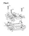
- a plastic capacitor holder 23 holds the film capacitors 22.
- the capacitor holder 23 includes a plurality of holding holes 23h, each shaped to hold one of the film capacitors 22.
- the capacitor holder 23, which holds the film capacitors 22, is coupled to the side of the coupling base 31 that is opposite to the end wall 12a of the suction housing member 12.
- a plurality of bosses 31f projects from the surface of the coupling base 31 that is opposite to the end wall 12a of the suction housing member 12.
- Bolts B1 are inserted through the cover 13 and fastened to the bosses 31f to couple the coupling base 31 to the cover 13. This joins the cover 13, the coupling base 31, and the motor driving circuit 20 and forms a module.
- a bolt B2 fastens the cover 13, which is joined with the coupling base 31 and the motor driving circuit 20, to the suction housing member 12.
- the capacitor holder 23 includes a peripheral portion including a plurality of (two are shown in Fig. 1 B) flanges 23f.
- Each flange 23f has a surface facing the coupling base 31 and including a positioning pin 41, which is also referred to as a projection.
- the positioning pin 41 is cylindrical and formed integrally with the corresponding flange 23f.
- the surface of the coupling base 31 opposite to the end wall 12a of the suction housing member 12 includes engagement recesses 42.
- Each engagement recess 42 functions as an engagement portion that engages with the corresponding one of the positioning pins 41.
- Each flange 23f includes an insertion hole 23a into which a bolt B3 is inserted.
- the surface of the coupling base 31 opposite to the end wall 12a of the suction housing member 12 includes threaded holes 31h.
- the bolt B3 is inserted into the insertion hole 23a and engaged with a corresponding one of the threaded holes 31 h. This fastens the capacitor holder 23 to the coupling base 31.
- each flange 23f includes a planar reinforcement 23b projecting from the surface of the flange 23f that is opposite to the coupling base 31. The reinforcement 23b is located between the corresponding positioning pin 41 and the corresponding insertion hole 23a.
- the engagement of the positioning pins 41 and the engagement recesses 42 positions the capacitor holder 23 relative to the coupling base 31. This restricts displacement of the capacitor holder 23 relative to the coupling base 31. Then, the capacitor holder 23, of which displacement is restricted, is fastened to the coupling base 31 with the bolts B3.
- each reinforcement 23b which reinforces the corresponding flange 23f, limits deformation of the flange 23f caused by the fastening force of the bolt B3.
- the leads 22a of the film capacitors 22 are not displaced from the corresponding connection locations of the circuit board 21. This facilitates connection of the film capacitors 22 to the circuit board 21.
- the cover 13, the coupling base 31, and the motor driving circuit 20 form a module.
- the coupling base 31 and the motor driving circuit 20 can be removed from the suction housing member 12 just by removing the cover 13 from the suction housing member 12. This facilitates maintenance of the motor driving circuit 20.
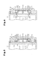
- the surface of the coupling base 31 that is opposite to the end wall 12a of the suction housing member 12 may include a plurality of positioning pins 41a, which function as projections.
- the surface of the capacitor holder 23 that faces the coupling base 31 may include engagement recesses 42A, which function as engagement portions that engage with the respective positioning pins 41A.
- the coupling base 31 may be omitted, and the capacitor holder 23 may be directly coupled to the end wall 12a of the suction housing member 12.
- the end wall 12a of the suction housing member 12 functions as a coupling member to which the capacitor holder 23 is coupled.
- the end wall 12a of the suction housing member 12 includes engagement recesses 42B that function as engagement portions engaged with the positioning pins 41.
- the surface of the coupling base 31 that is opposite to the end wall 12a of the suction housing member 12 may include a wall functioning as a projection that engages with the peripheral wall of the capacitor holder 23.
- the peripheral wall of the capacitor holder 23 functions as an engagement portion that engages with the wall.
- the positioning pins 41 and the number of the engagement recesses 42 there is no limitation to the number of the positioning pins 41 and the number of the engagement recesses 42.
- the positioning pin 41 is shaped as a rectangular or triangular prism.
- the positioning pins 41 do not have to be formed integrally with the flanges 23f of the capacitor holder 23.
- the positioning pins 41 may be discrete from the capacitor holder 23.
- the positioning pin 41 and the insertion hole 23a do not have to be arranged in the same flange 23f and may be arranged in separate flanges.
- Each flange 23f does not have to include the reinforcement 23b.
- the number of the film capacitors 22 is not limited.
- the capacitors may include an electrolytic capacitor, for example.
- the motor driving circuit 20 may be located radially outward from the rotation shaft 19.
- the compression unit 15 may be of a piston type or a vane type.
Landscapes
- Engineering & Computer Science (AREA)
- Mechanical Engineering (AREA)
- General Engineering & Computer Science (AREA)
- Manufacturing & Machinery (AREA)
- Microelectronics & Electronic Packaging (AREA)
- Power Engineering (AREA)
- Compressor (AREA)
Applications Claiming Priority (1)
| Application Number | Priority Date | Filing Date | Title |
|---|---|---|---|
| JP2013132613A JP5861673B2 (ja) | 2013-06-25 | 2013-06-25 | 電動圧縮機 |
Publications (2)
| Publication Number | Publication Date |
|---|---|
| EP2818705A1 true EP2818705A1 (fr) | 2014-12-31 |
| EP2818705B1 EP2818705B1 (fr) | 2016-04-27 |
Family
ID=50979613
Family Applications (1)
| Application Number | Title | Priority Date | Filing Date |
|---|---|---|---|
| EP14173415.2A Active EP2818705B1 (fr) | 2013-06-25 | 2014-06-23 | Compresseur motorisé |
Country Status (5)
| Country | Link |
|---|---|
| US (1) | US10087942B2 (fr) |
| EP (1) | EP2818705B1 (fr) |
| JP (1) | JP5861673B2 (fr) |
| KR (1) | KR101734141B1 (fr) |
| CN (1) | CN104251212B (fr) |
Cited By (3)
| Publication number | Priority date | Publication date | Assignee | Title |
|---|---|---|---|---|
| EP3168476A1 (fr) * | 2015-11-16 | 2017-05-17 | Valeo Japan Co., Ltd. | Boîtier a dispositif de controle integre et compresseur electrique comprenant ledit boîtier |
| EP3261230A1 (fr) * | 2016-06-21 | 2017-12-27 | Jtekt Corporation | Unité de moteur électromécanique |
| FR3071696A1 (fr) * | 2017-09-27 | 2019-03-29 | Valeo Japan Co., Ltd. | Boitier de commande d'un compresseur electrique prevu pour le refroidissement d'au moins un composant electronique |
Families Citing this family (10)
| Publication number | Priority date | Publication date | Assignee | Title |
|---|---|---|---|---|
| CN107542671B (zh) * | 2016-06-23 | 2020-09-15 | 浙江三花汽车零部件有限公司 | 电子泵 |
| JP6814607B2 (ja) | 2016-11-11 | 2021-01-20 | 三菱重工サーマルシステムズ株式会社 | 電動圧縮機 |
| JP7035999B2 (ja) * | 2018-12-27 | 2022-03-15 | 株式会社豊田自動織機 | 電動圧縮機 |
| JP7088111B2 (ja) * | 2019-03-28 | 2022-06-21 | 株式会社豊田自動織機 | 電動圧縮機 |
| JP2020198767A (ja) * | 2019-06-05 | 2020-12-10 | 三菱電機株式会社 | 電動機 |
| JP2021092168A (ja) * | 2019-12-09 | 2021-06-17 | 株式会社豊田自動織機 | 電動圧縮機、及び電動圧縮機の製造方法 |
| JP7400459B2 (ja) * | 2019-12-26 | 2023-12-19 | 株式会社豊田自動織機 | 電動圧縮機 |
| DE102021203966A1 (de) | 2021-04-21 | 2022-10-27 | Robert Bosch Gesellschaft mit beschränkter Haftung | Axialkolbenmaschine |
| JP7567696B2 (ja) * | 2021-07-08 | 2024-10-16 | 株式会社豊田自動織機 | 電動圧縮機 |
| JP7855987B2 (ja) * | 2022-10-31 | 2026-05-11 | 株式会社豊田自動織機 | 電動圧縮機 |
Citations (6)
| Publication number | Priority date | Publication date | Assignee | Title |
|---|---|---|---|---|
| EP1363026A2 (fr) * | 2002-04-26 | 2003-11-19 | Denso Corporation | Onduleur intégré moteur pour un véhicule automobile |
| EP1450044A2 (fr) * | 2003-02-19 | 2004-08-25 | Kabushiki Kaisha Toyota Jidoshokki | Compresseur électrique et son procédé d'assemblage |
| WO2006080698A1 (fr) * | 2004-11-03 | 2006-08-03 | Texas Instruments Korea Limited | Dispositif de fixation pour le montage d'un boitier de connexion pour compresseur de refrigerateur |
| JP2007263061A (ja) | 2006-03-29 | 2007-10-11 | Toyota Industries Corp | 電動コンプレッサ |
| EP2500516A2 (fr) * | 2011-03-16 | 2012-09-19 | Kabushiki Kaisha Toyota Jidoshokki | Compresseur |
| EP2549844A1 (fr) * | 2011-07-19 | 2013-01-23 | Kabushiki Kaisha Toyota Jidoshokki | Structure pour fixer une pièce électrique de compresseur motorisé |
Family Cites Families (8)
| Publication number | Priority date | Publication date | Assignee | Title |
|---|---|---|---|---|
| JP2002070743A (ja) * | 2000-08-29 | 2002-03-08 | Sanden Corp | 冷媒圧縮用電動式圧縮機 |
| JP2004044555A (ja) | 2002-07-15 | 2004-02-12 | Toyota Industries Corp | 電動コンプレッサ |
| JP5517650B2 (ja) | 2010-02-01 | 2014-06-11 | 三菱重工業株式会社 | インバータ一体型電動圧縮機 |
| JP5785365B2 (ja) * | 2010-02-26 | 2015-09-30 | 株式会社ケーヒン | スイッチング電源 |
| JP5574794B2 (ja) * | 2010-04-14 | 2014-08-20 | 三菱重工業株式会社 | インバータ一体型電動圧縮機 |
| JP5626200B2 (ja) * | 2011-01-06 | 2014-11-19 | 株式会社豊田自動織機 | 電気部品の固定構造 |
| JP5855899B2 (ja) * | 2011-10-27 | 2016-02-09 | 日立オートモティブシステムズ株式会社 | Dc−dcコンバータ及び電力変換装置 |
| JP5924174B2 (ja) | 2012-07-20 | 2016-05-25 | 株式会社豊田自動織機 | 電動圧縮機 |
-
2013
- 2013-06-25 JP JP2013132613A patent/JP5861673B2/ja active Active
-
2014
- 2014-06-23 EP EP14173415.2A patent/EP2818705B1/fr active Active
- 2014-06-23 CN CN201410284056.4A patent/CN104251212B/zh active Active
- 2014-06-23 KR KR1020140076425A patent/KR101734141B1/ko active Active
- 2014-06-24 US US14/312,848 patent/US10087942B2/en active Active
Patent Citations (6)
| Publication number | Priority date | Publication date | Assignee | Title |
|---|---|---|---|---|
| EP1363026A2 (fr) * | 2002-04-26 | 2003-11-19 | Denso Corporation | Onduleur intégré moteur pour un véhicule automobile |
| EP1450044A2 (fr) * | 2003-02-19 | 2004-08-25 | Kabushiki Kaisha Toyota Jidoshokki | Compresseur électrique et son procédé d'assemblage |
| WO2006080698A1 (fr) * | 2004-11-03 | 2006-08-03 | Texas Instruments Korea Limited | Dispositif de fixation pour le montage d'un boitier de connexion pour compresseur de refrigerateur |
| JP2007263061A (ja) | 2006-03-29 | 2007-10-11 | Toyota Industries Corp | 電動コンプレッサ |
| EP2500516A2 (fr) * | 2011-03-16 | 2012-09-19 | Kabushiki Kaisha Toyota Jidoshokki | Compresseur |
| EP2549844A1 (fr) * | 2011-07-19 | 2013-01-23 | Kabushiki Kaisha Toyota Jidoshokki | Structure pour fixer une pièce électrique de compresseur motorisé |
Cited By (5)
| Publication number | Priority date | Publication date | Assignee | Title |
|---|---|---|---|---|
| EP3168476A1 (fr) * | 2015-11-16 | 2017-05-17 | Valeo Japan Co., Ltd. | Boîtier a dispositif de controle integre et compresseur electrique comprenant ledit boîtier |
| FR3043878A1 (fr) * | 2015-11-16 | 2017-05-19 | Valeo Japan Co Ltd | Boitier a dispositif de controle integre et compresseur electrique comprenant ledit boitier |
| EP3261230A1 (fr) * | 2016-06-21 | 2017-12-27 | Jtekt Corporation | Unité de moteur électromécanique |
| US10461611B2 (en) | 2016-06-21 | 2019-10-29 | Jtekt Corporation | Electromechanical motor unit |
| FR3071696A1 (fr) * | 2017-09-27 | 2019-03-29 | Valeo Japan Co., Ltd. | Boitier de commande d'un compresseur electrique prevu pour le refroidissement d'au moins un composant electronique |
Also Published As
| Publication number | Publication date |
|---|---|
| JP5861673B2 (ja) | 2016-02-16 |
| CN104251212B (zh) | 2016-09-28 |
| JP2015007390A (ja) | 2015-01-15 |
| CN104251212A (zh) | 2014-12-31 |
| KR101734141B1 (ko) | 2017-05-11 |
| US20140377094A1 (en) | 2014-12-25 |
| EP2818705B1 (fr) | 2016-04-27 |
| US10087942B2 (en) | 2018-10-02 |
| KR20150000837A (ko) | 2015-01-05 |
Similar Documents
| Publication | Publication Date | Title |
|---|---|---|
| EP2818705B1 (fr) | Compresseur motorisé | |
| KR101178753B1 (ko) | 전동 압축기 | |
| KR102483243B1 (ko) | 전동 압축기 | |
| KR102625341B1 (ko) | 전동 압축기 | |
| JP5708592B2 (ja) | 電動圧縮機 | |
| JP2015040538A (ja) | 電動圧縮機 | |
| JP6337749B2 (ja) | 電動圧縮機 | |
| JP2016096316A (ja) | 車載用電子機器 | |
| EP3109474A1 (fr) | Compresseur électrique à spirales | |
| EP2818717A1 (fr) | Compresseur motorisé | |
| US11888359B2 (en) | Motor-driven compressor | |
| EP2818706A1 (fr) | Compresseur motorisé | |
| KR101591027B1 (ko) | 전동 압축기 | |
| KR102191953B1 (ko) | 전동 압축기 | |
| JP6760182B2 (ja) | 電動圧縮機 | |
| CN113027764A (zh) | 电动压缩机及电动压缩机的制造方法 | |
| WO2017163539A1 (fr) | Machine à fluide à entraînement électrique | |
| JP2018168834A (ja) | 電動圧縮機 |
Legal Events
| Date | Code | Title | Description |
|---|---|---|---|
| PUAI | Public reference made under article 153(3) epc to a published international application that has entered the european phase |
Free format text: ORIGINAL CODE: 0009012 |
|
| 17P | Request for examination filed |
Effective date: 20140623 |
|
| AK | Designated contracting states |
Kind code of ref document: A1 Designated state(s): AL AT BE BG CH CY CZ DE DK EE ES FI FR GB GR HR HU IE IS IT LI LT LU LV MC MK MT NL NO PL PT RO RS SE SI SK SM TR |
|
| AX | Request for extension of the european patent |
Extension state: BA ME |
|
| RIC1 | Information provided on ipc code assigned before grant |
Ipc: F04B 27/08 20060101AFI20150915BHEP Ipc: F04B 35/04 20060101ALI20150915BHEP Ipc: F04B 39/12 20060101ALI20150915BHEP Ipc: H02K 11/00 20060101ALI20150915BHEP Ipc: F04C 23/00 20060101ALI20150915BHEP |
|
| GRAP | Despatch of communication of intention to grant a patent |
Free format text: ORIGINAL CODE: EPIDOSNIGR1 |
|
| INTG | Intention to grant announced |
Effective date: 20151111 |
|
| GRAS | Grant fee paid |
Free format text: ORIGINAL CODE: EPIDOSNIGR3 |
|
| GRAA | (expected) grant |
Free format text: ORIGINAL CODE: 0009210 |
|
| AK | Designated contracting states |
Kind code of ref document: B1 Designated state(s): AL AT BE BG CH CY CZ DE DK EE ES FI FR GB GR HR HU IE IS IT LI LT LU LV MC MK MT NL NO PL PT RO RS SE SI SK SM TR |
|
| REG | Reference to a national code |
Ref country code: GB Ref legal event code: FG4D |
|
| REG | Reference to a national code |
Ref country code: CH Ref legal event code: EP |
|
| REG | Reference to a national code |
Ref country code: AT Ref legal event code: REF Ref document number: 795119 Country of ref document: AT Kind code of ref document: T Effective date: 20160515 |
|
| REG | Reference to a national code |
Ref country code: IE Ref legal event code: FG4D |
|
| REG | Reference to a national code |
Ref country code: DE Ref legal event code: R096 Ref document number: 602014001670 Country of ref document: DE |
|
| REG | Reference to a national code |
Ref country code: LT Ref legal event code: MG4D |
|
| REG | Reference to a national code |
Ref country code: NL Ref legal event code: MP Effective date: 20160427 |
|
| REG | Reference to a national code |
Ref country code: AT Ref legal event code: MK05 Ref document number: 795119 Country of ref document: AT Kind code of ref document: T Effective date: 20160427 |
|
| PG25 | Lapsed in a contracting state [announced via postgrant information from national office to epo] |
Ref country code: NL Free format text: LAPSE BECAUSE OF FAILURE TO SUBMIT A TRANSLATION OF THE DESCRIPTION OR TO PAY THE FEE WITHIN THE PRESCRIBED TIME-LIMIT Effective date: 20160427 |
|
| PG25 | Lapsed in a contracting state [announced via postgrant information from national office to epo] |
Ref country code: PL Free format text: LAPSE BECAUSE OF FAILURE TO SUBMIT A TRANSLATION OF THE DESCRIPTION OR TO PAY THE FEE WITHIN THE PRESCRIBED TIME-LIMIT Effective date: 20160427 Ref country code: FI Free format text: LAPSE BECAUSE OF FAILURE TO SUBMIT A TRANSLATION OF THE DESCRIPTION OR TO PAY THE FEE WITHIN THE PRESCRIBED TIME-LIMIT Effective date: 20160427 Ref country code: NO Free format text: LAPSE BECAUSE OF FAILURE TO SUBMIT A TRANSLATION OF THE DESCRIPTION OR TO PAY THE FEE WITHIN THE PRESCRIBED TIME-LIMIT Effective date: 20160727 Ref country code: LT Free format text: LAPSE BECAUSE OF FAILURE TO SUBMIT A TRANSLATION OF THE DESCRIPTION OR TO PAY THE FEE WITHIN THE PRESCRIBED TIME-LIMIT Effective date: 20160427 |
|
| PG25 | Lapsed in a contracting state [announced via postgrant information from national office to epo] |
Ref country code: AT Free format text: LAPSE BECAUSE OF FAILURE TO SUBMIT A TRANSLATION OF THE DESCRIPTION OR TO PAY THE FEE WITHIN THE PRESCRIBED TIME-LIMIT Effective date: 20160427 Ref country code: SE Free format text: LAPSE BECAUSE OF FAILURE TO SUBMIT A TRANSLATION OF THE DESCRIPTION OR TO PAY THE FEE WITHIN THE PRESCRIBED TIME-LIMIT Effective date: 20160427 Ref country code: HR Free format text: LAPSE BECAUSE OF FAILURE TO SUBMIT A TRANSLATION OF THE DESCRIPTION OR TO PAY THE FEE WITHIN THE PRESCRIBED TIME-LIMIT Effective date: 20160427 Ref country code: RS Free format text: LAPSE BECAUSE OF FAILURE TO SUBMIT A TRANSLATION OF THE DESCRIPTION OR TO PAY THE FEE WITHIN THE PRESCRIBED TIME-LIMIT Effective date: 20160427 Ref country code: GR Free format text: LAPSE BECAUSE OF FAILURE TO SUBMIT A TRANSLATION OF THE DESCRIPTION OR TO PAY THE FEE WITHIN THE PRESCRIBED TIME-LIMIT Effective date: 20160728 Ref country code: PT Free format text: LAPSE BECAUSE OF FAILURE TO SUBMIT A TRANSLATION OF THE DESCRIPTION OR TO PAY THE FEE WITHIN THE PRESCRIBED TIME-LIMIT Effective date: 20160829 Ref country code: ES Free format text: LAPSE BECAUSE OF FAILURE TO SUBMIT A TRANSLATION OF THE DESCRIPTION OR TO PAY THE FEE WITHIN THE PRESCRIBED TIME-LIMIT Effective date: 20160427 Ref country code: LV Free format text: LAPSE BECAUSE OF FAILURE TO SUBMIT A TRANSLATION OF THE DESCRIPTION OR TO PAY THE FEE WITHIN THE PRESCRIBED TIME-LIMIT Effective date: 20160427 |
|
| PG25 | Lapsed in a contracting state [announced via postgrant information from national office to epo] |
Ref country code: BE Free format text: LAPSE BECAUSE OF FAILURE TO SUBMIT A TRANSLATION OF THE DESCRIPTION OR TO PAY THE FEE WITHIN THE PRESCRIBED TIME-LIMIT Effective date: 20160427 Ref country code: IT Free format text: LAPSE BECAUSE OF FAILURE TO SUBMIT A TRANSLATION OF THE DESCRIPTION OR TO PAY THE FEE WITHIN THE PRESCRIBED TIME-LIMIT Effective date: 20160427 |
|
| REG | Reference to a national code |
Ref country code: DE Ref legal event code: R097 Ref document number: 602014001670 Country of ref document: DE |
|
| PG25 | Lapsed in a contracting state [announced via postgrant information from national office to epo] |
Ref country code: CZ Free format text: LAPSE BECAUSE OF FAILURE TO SUBMIT A TRANSLATION OF THE DESCRIPTION OR TO PAY THE FEE WITHIN THE PRESCRIBED TIME-LIMIT Effective date: 20160427 Ref country code: SK Free format text: LAPSE BECAUSE OF FAILURE TO SUBMIT A TRANSLATION OF THE DESCRIPTION OR TO PAY THE FEE WITHIN THE PRESCRIBED TIME-LIMIT Effective date: 20160427 Ref country code: EE Free format text: LAPSE BECAUSE OF FAILURE TO SUBMIT A TRANSLATION OF THE DESCRIPTION OR TO PAY THE FEE WITHIN THE PRESCRIBED TIME-LIMIT Effective date: 20160427 Ref country code: MC Free format text: LAPSE BECAUSE OF FAILURE TO SUBMIT A TRANSLATION OF THE DESCRIPTION OR TO PAY THE FEE WITHIN THE PRESCRIBED TIME-LIMIT Effective date: 20160427 Ref country code: RO Free format text: LAPSE BECAUSE OF FAILURE TO SUBMIT A TRANSLATION OF THE DESCRIPTION OR TO PAY THE FEE WITHIN THE PRESCRIBED TIME-LIMIT Effective date: 20160427 Ref country code: DK Free format text: LAPSE BECAUSE OF FAILURE TO SUBMIT A TRANSLATION OF THE DESCRIPTION OR TO PAY THE FEE WITHIN THE PRESCRIBED TIME-LIMIT Effective date: 20160427 |
|
| PG25 | Lapsed in a contracting state [announced via postgrant information from national office to epo] |
Ref country code: SM Free format text: LAPSE BECAUSE OF FAILURE TO SUBMIT A TRANSLATION OF THE DESCRIPTION OR TO PAY THE FEE WITHIN THE PRESCRIBED TIME-LIMIT Effective date: 20160427 |
|
| PLBE | No opposition filed within time limit |
Free format text: ORIGINAL CODE: 0009261 |
|
| STAA | Information on the status of an ep patent application or granted ep patent |
Free format text: STATUS: NO OPPOSITION FILED WITHIN TIME LIMIT |
|
| REG | Reference to a national code |
Ref country code: IE Ref legal event code: MM4A |
|
| REG | Reference to a national code |
Ref country code: FR Ref legal event code: ST Effective date: 20170228 |
|
| 26N | No opposition filed |
Effective date: 20170130 |
|
| PG25 | Lapsed in a contracting state [announced via postgrant information from national office to epo] |
Ref country code: FR Free format text: LAPSE BECAUSE OF NON-PAYMENT OF DUE FEES Effective date: 20160630 |
|
| PG25 | Lapsed in a contracting state [announced via postgrant information from national office to epo] |
Ref country code: IE Free format text: LAPSE BECAUSE OF NON-PAYMENT OF DUE FEES Effective date: 20160623 Ref country code: SI Free format text: LAPSE BECAUSE OF FAILURE TO SUBMIT A TRANSLATION OF THE DESCRIPTION OR TO PAY THE FEE WITHIN THE PRESCRIBED TIME-LIMIT Effective date: 20160427 |
|
| REG | Reference to a national code |
Ref country code: CH Ref legal event code: PL |
|
| PG25 | Lapsed in a contracting state [announced via postgrant information from national office to epo] |
Ref country code: CH Free format text: LAPSE BECAUSE OF NON-PAYMENT OF DUE FEES Effective date: 20170630 Ref country code: LI Free format text: LAPSE BECAUSE OF NON-PAYMENT OF DUE FEES Effective date: 20170630 |
|
| PG25 | Lapsed in a contracting state [announced via postgrant information from national office to epo] |
Ref country code: HU Free format text: LAPSE BECAUSE OF FAILURE TO SUBMIT A TRANSLATION OF THE DESCRIPTION OR TO PAY THE FEE WITHIN THE PRESCRIBED TIME-LIMIT; INVALID AB INITIO Effective date: 20140623 |
|
| PG25 | Lapsed in a contracting state [announced via postgrant information from national office to epo] |
Ref country code: LU Free format text: LAPSE BECAUSE OF NON-PAYMENT OF DUE FEES Effective date: 20160623 Ref country code: IS Free format text: LAPSE BECAUSE OF FAILURE TO SUBMIT A TRANSLATION OF THE DESCRIPTION OR TO PAY THE FEE WITHIN THE PRESCRIBED TIME-LIMIT Effective date: 20160427 Ref country code: MT Free format text: LAPSE BECAUSE OF NON-PAYMENT OF DUE FEES Effective date: 20160630 Ref country code: MK Free format text: LAPSE BECAUSE OF FAILURE TO SUBMIT A TRANSLATION OF THE DESCRIPTION OR TO PAY THE FEE WITHIN THE PRESCRIBED TIME-LIMIT Effective date: 20160427 Ref country code: CY Free format text: LAPSE BECAUSE OF FAILURE TO SUBMIT A TRANSLATION OF THE DESCRIPTION OR TO PAY THE FEE WITHIN THE PRESCRIBED TIME-LIMIT Effective date: 20160427 |
|
| PG25 | Lapsed in a contracting state [announced via postgrant information from national office to epo] |
Ref country code: BG Free format text: LAPSE BECAUSE OF FAILURE TO SUBMIT A TRANSLATION OF THE DESCRIPTION OR TO PAY THE FEE WITHIN THE PRESCRIBED TIME-LIMIT Effective date: 20160427 |
|
| PG25 | Lapsed in a contracting state [announced via postgrant information from national office to epo] |
Ref country code: AL Free format text: LAPSE BECAUSE OF FAILURE TO SUBMIT A TRANSLATION OF THE DESCRIPTION OR TO PAY THE FEE WITHIN THE PRESCRIBED TIME-LIMIT Effective date: 20160427 Ref country code: TR Free format text: LAPSE BECAUSE OF FAILURE TO SUBMIT A TRANSLATION OF THE DESCRIPTION OR TO PAY THE FEE WITHIN THE PRESCRIBED TIME-LIMIT Effective date: 20160427 |
|
| GBPC | Gb: european patent ceased through non-payment of renewal fee |
Effective date: 20180623 |
|
| PG25 | Lapsed in a contracting state [announced via postgrant information from national office to epo] |
Ref country code: GB Free format text: LAPSE BECAUSE OF NON-PAYMENT OF DUE FEES Effective date: 20180623 |
|
| P01 | Opt-out of the competence of the unified patent court (upc) registered |
Effective date: 20230519 |
|
| PGFP | Annual fee paid to national office [announced via postgrant information from national office to epo] |
Ref country code: DE Payment date: 20250429 Year of fee payment: 12 |