WO2017163539A1 - Machine à fluide à entraînement électrique - Google Patents
Machine à fluide à entraînement électrique Download PDFInfo
- Publication number
- WO2017163539A1 WO2017163539A1 PCT/JP2017/000514 JP2017000514W WO2017163539A1 WO 2017163539 A1 WO2017163539 A1 WO 2017163539A1 JP 2017000514 W JP2017000514 W JP 2017000514W WO 2017163539 A1 WO2017163539 A1 WO 2017163539A1
- Authority
- WO
- WIPO (PCT)
- Prior art keywords
- motor
- cluster block
- hole
- rotary shaft
- stator
- Prior art date
- Legal status (The legal status is an assumption and is not a legal conclusion. Google has not performed a legal analysis and makes no representation as to the accuracy of the status listed.)
- Ceased
Links
Images


Classifications
-
- F—MECHANICAL ENGINEERING; LIGHTING; HEATING; WEAPONS; BLASTING
- F04—POSITIVE - DISPLACEMENT MACHINES FOR LIQUIDS; PUMPS FOR LIQUIDS OR ELASTIC FLUIDS
- F04B—POSITIVE-DISPLACEMENT MACHINES FOR LIQUIDS; PUMPS
- F04B39/00—Component parts, details, or accessories, of pumps or pumping systems specially adapted for elastic fluids, not otherwise provided for in, or of interest apart from, groups F04B25/00 - F04B37/00
-
- F—MECHANICAL ENGINEERING; LIGHTING; HEATING; WEAPONS; BLASTING
- F04—POSITIVE - DISPLACEMENT MACHINES FOR LIQUIDS; PUMPS FOR LIQUIDS OR ELASTIC FLUIDS
- F04C—ROTARY-PISTON, OR OSCILLATING-PISTON, POSITIVE-DISPLACEMENT MACHINES FOR LIQUIDS; ROTARY-PISTON, OR OSCILLATING-PISTON, POSITIVE-DISPLACEMENT PUMPS
- F04C29/00—Component parts, details or accessories of pumps or pumping installations, not provided for in groups F04C18/00 - F04C28/00
-
- H—ELECTRICITY
- H02—GENERATION; CONVERSION OR DISTRIBUTION OF ELECTRIC POWER
- H02K—DYNAMO-ELECTRIC MACHINES
- H02K5/00—Casings; Enclosures; Supports
- H02K5/04—Casings or enclosures characterised by the shape, form or construction thereof
- H02K5/22—Auxiliary parts of casings not covered by groups H02K5/06-H02K5/20, e.g. shaped to form connection boxes or terminal boxes
Definitions
- the present invention relates to an electric fluid machine having an electric motor for rotating a rotating shaft and a drive circuit for driving the electric motor.
- the electric compressor includes a compression unit that is driven by the rotation of the rotation shaft to compress the refrigerant.
- the housing of the electric compressor is cylindrical and accommodates the compression unit and the electric motor.
- the electric motor includes a stator fixed to the inner peripheral surface of the housing, and a rotor that rotates integrally with the rotation shaft.
- the stator has a cylindrical stator core and a coil wound around the stator core. An annular coil end projects from an end face of the stator core located in the axial direction of the rotation shaft. Motor wiring is drawn out from the coil end.
- the drive circuit is provided with circuit wiring electrically connected to the motor wiring.
- an insulating cluster block is disposed which accommodates a conductive member for electrically connecting the motor wiring and the circuit wiring.
- the cluster block has a first insertion hole into which the motor wiring is inserted and a second insertion hole into which the circuit wiring is inserted.
- a stator coil end cover is attached to a bobbin of a stator.
- Two claws are integrally formed on the stator coil end cover.
- two mounting holes are provided in the cluster block. Then, each claw portion is inserted into each mounting hole, and each claw portion is fitted to each mounting hole, whereby the cluster block is mounted to the stator via the stator coil end cover.
- the respective claws may come off the respective mounting holes, and the cluster block may come off the stator.
- the present invention has been made to solve the above-mentioned problems, and it is an object of the present invention to provide an electric fluid machine in which a cluster block is less likely to come off the stator when circuit wiring is pulled out of the cluster block. is there.
- An electric fluid machine to solve the above problems is a cylindrical housing, a rotary shaft housed in the housing, and an electric motor housed in the housing and rotating the rotary shaft, the stator core and the like
- An electric motor including a stator having a coil wound around a stator core, a drive circuit for driving the electric motor, a motor wiring drawn from the coil, a circuit wiring provided in the drive circuit, and the housing
- An electrically-conductive fluid machine including: an insulating, hollow cluster block that accommodates and accommodates a conductive member electrically connected to the motor wiring and the circuit wiring, wherein the axial line of the rotation shaft And a mounting member attached to the stator, and the cluster block includes the rotation member.
- a connecting portion extending in the axial direction, a partition wall of the cluster block, and a first insertion hole into which the motor wiring is inserted; and a partition wall of the cluster block in the axial direction of the rotation shaft;
- the insertion direction in which the convex portion is inserted into the hole crosses the insertion direction in which the circuit wiring is inserted into the second insertion hole. Therefore, when the circuit wiring is pulled out from the second insertion hole, the cluster block is unlikely to come off the stator.
- the difference between the circumferential dimension of the rotary shaft in the hole and the circumferential dimension of the rotary shaft in the convex portion is the axial dimension of the rotary shaft in the hole It is preferable that the difference is larger than the difference between the dimension of the convex portion in the axial direction of the rotation axis.
- the connecting portion can move in the circumferential direction of the rotating shaft with respect to the mounting member, the cluster block can be moved even if positional deviation of the stator core occurs in the circumferential direction of the rotating shaft from the position aimed by the stator core. Circuit wiring can be inserted into the Furthermore, when the circuit wiring is pulled out from the second insertion hole, the cluster block is less likely to come off the stator.
- connection portion is integrally formed with the cluster block. According to this, the configuration can be simplified as compared with the case where the connecting part is separate from the cluster block.
- connection portion be sandwiched between the extension portion and the coil. According to this, the attachment to the stator in the cluster block can be made strong.
- the cluster block when the circuit wiring is pulled out of the cluster block, the cluster block does not easily come off the stator.
- the side sectional view which shows the electric compressor in embodiment.
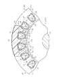
- Sectional drawing which shows the attachment state of an attachment member and a stator.
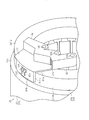
- the perspective view of a cluster block and the periphery of an attachment member The perspective view of the periphery of a cluster block.
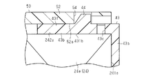
- Sectional drawing which shows the periphery of a convex part and a hole.
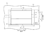
- the top view which shows the periphery of a convex part and a hole.
- the housing 11 of the electric compressor 10 has a bottomed cylindrical discharge housing 12 and a bottomed cylindrical motor housing 13 connected to the discharge housing 12.
- the discharge housing 12 and the motor housing 13 are made of a metal material (for example, made of aluminum).
- the motor housing 13 has a bottom wall 13 e and a side wall 13 a cylindrically extending from the outer peripheral edge of the bottom wall 13 e.
- a suction port 13h is formed on the side wall 13a.
- the suction port 13 h is connected to an external refrigerant circuit (not shown).
- a discharge chamber 12 a is formed in the discharge housing 12. In the discharge housing 12, a discharge port 12h communicating with the discharge chamber 12a is formed.
- the discharge port 12 h is connected to an external refrigerant circuit.
- the rotation shaft 14 is accommodated in the motor housing 13. Further, in the motor housing 13, a compression unit 15 that compresses the refrigerant by rotation of the rotary shaft 14 and an electric motor 20 that rotates the rotary shaft 14 are accommodated.
- the compression unit 15 and the electric motor 20 are arranged side by side in the direction (axial direction) in which the rotation axis L of the rotation shaft 14 extends.
- the electric motor 20 is disposed closer to the bottom wall 13 e of the motor housing 13 than the compression unit 15.
- a shaft support member 16 is provided between the compression unit 15 and the electric motor 20.
- An insertion hole 16 h through which one end of the rotary shaft 14 is inserted is formed in the central portion of the pivot support member 16.
- a bearing 17 a is provided between the insertion hole 16 h and one end of the rotary shaft 14.
- One end of the rotary shaft 14 is rotatably supported by the bearing 16 via a bearing 17 a.
- a cylindrical bearing 18 projects from the bottom wall 13 e of the motor housing 13.
- the other end of the rotary shaft 14 is inserted inside the bearing portion 18.
- a bearing 17 b is provided between the bearing 18 and the other end of the rotating shaft 14.
- the other end of the rotating shaft 14 is rotatably supported by the bearing 18 via a bearing 17 b.
- the compression unit 15 includes a fixed scroll 15 a fixed to the motor housing 13 and a movable scroll 15 b disposed to face the fixed scroll 15 a.
- the fixed scroll 15a and the movable scroll 15b mesh with each other.
- a compression chamber 15c whose volume can be changed is partitioned.
- the refrigerant sucked into the motor housing 13 from the suction port 13h is sucked into the compression chamber 15c by the turning (suction operation) of the movable scroll 15b.
- the refrigerant in the compression chamber 15c is compressed by the turning (discharge operation) of the movable scroll 15b and is discharged to the discharge chamber 12a.
- the refrigerant discharged to the discharge chamber 12a flows out to the external refrigerant circuit through the discharge port 12h, and returns to the inside of the motor housing 13 through the suction port 13h.
- a bottomed cylindrical cover member 19 is attached to the bottom wall 13 e of the motor housing 13.
- a drive circuit 30 for driving the electric motor 20 is accommodated in a space partitioned by the bottom wall 13 e of the motor housing 13 and the cover member 19.
- the compression unit 15, the electric motor 20 and the drive circuit 30 are arranged in this order along the rotation axis L of the rotation shaft 14.
- the electric motor 20 includes a rotor 21 that rotates integrally with the rotating shaft 14, and a stator 22 that surrounds the rotor 21.
- the rotor 21 has a rotor core 21 a fixed to the rotating shaft 14 and a plurality of permanent magnets (not shown) provided on the rotor core 21 a.
- the stator 22 has a cylindrical stator core 23 and a coil 24 wound around the stator core 23.
- the stator core 23 is assembled to the motor housing 13 by being fitted inside the motor housing 13 by shrink fitting.
- the motor housing 13 is heated and expanded to make the inner diameter of the motor housing 13 larger than the outer diameter of the stator core 23, and then the stator core 23 is inserted into the motor housing 13 to a predetermined shrink fit position. Then, the inner circumferential surface of the motor housing 13 is brought into pressure contact with the outer circumferential surface of the stator core 23 by the contraction accompanying the transition of the motor housing 13 to the normal temperature.
- a plurality of teeth 25 are arranged side by side in the circumferential direction of the rotating shaft 14. Slots 26 are formed between the teeth 25 adjacent in the circumferential direction of the rotating shaft 14. The plurality of slots 26 are arranged at equal pitches in the circumferential direction of the rotation shaft 14.
- the insulating sheet 27 is provided to extend along the axial direction of the rotating shaft 14 in the slot 26. Further, both axial ends of the insulating sheet 27 in the axial direction of the rotary shaft 14 project from both end faces 23 e of the stator core 23 located in the axial direction of the rotary shaft 14.
- cuff portions 27 e are formed bent at both axial end portions of the rotary shaft 14 in each insulating sheet 27, and the bent end of each cuff portion 27 e is engaged with each end face 23 e of the stator core 23. It has been stopped. Thus, the axial displacement of the insulating sheet 27 with respect to the stator core 23 in the slot 26 is prevented.
- the coil 24 is wound around the teeth 25 via a cylindrical insulating sheet 27. A portion of the coil 24 annularly protrudes from both end surfaces 23 e of the stator core 23 in the axial direction of the rotating shaft 14 to form a coil end 24 e.
- a part of the coil 24 is drawn out from the coil end 24 e disposed opposite to the bottom wall 13 e of the motor housing 13 as a motor wire 28 in a state of being coated with an insulating film. Specifically, three motor wires 28 are drawn out from the coil end 24 e corresponding to the U-phase, V-phase and W-phase coils 24.
- the gap 29 is a space formed by projecting both end portions in the axial direction of the rotary shaft 14 in the insulating sheet 27 from the end face 23 e of the stator core 23. And, by forming the gap 29, insulation between the end face 23e of the stator core 23 and the coil end 24e is secured.
- the drive circuit 30 is provided with three circuit wires 31 (only one is shown in FIG. 1) corresponding to the motor wires 28 of each phase.
- Three circuit wirings 31 extend from the drive circuit 30 into the motor housing 13 through the bottom wall 13 e of the motor housing 13.
- the cluster block 40 includes a main body 42 that accommodates the conductive member 41.
- a portion of the main body 42 is disposed radially inward of the rotary shaft 14 with respect to the coil end 24 e. That is, a part of the main body 42 and a part of the coil end 24 e are opposed in the radial direction of the rotating shaft 14.
- the main body portion 42 is constituted by three hollow prismatic members, and the three members are integrated in a state of being juxtaposed in the circumferential direction of the rotation shaft 14.
- the main body portion 42 has three first insertion holes 42 a into which the motor wires 28 are inserted, and three second insertion holes 42 b into which the circuit wires 31 are inserted.
- the first insertion hole 42a and the second insertion hole 42b are provided in each of the three members.
- Each first insertion hole 42 a penetrates the partition wall of the main body 42 in the radial direction of the rotary shaft 14.
- Each second insertion hole 42 b is disposed radially inward of the coil end 24 e with respect to the rotary shaft 14 and penetrates the partition wall of the main body 42 in the axial direction of the rotary shaft 14.
- Each motor wire 28 is inserted into each first insertion hole 42 a and connected to each conductive member 41.
- Each circuit wiring 31 is inserted into each second insertion hole 42 b and connected to each conductive member 41. Therefore, each motor wire 28 and each circuit wire 31 are electrically connected via each conductive member 41.
- the electric power controlled by the drive circuit 30 is supplied to the electric motor 20 through the circuit wiring 31, the conductive members 41, and the motor wiring 28, and the electric motor 20 is driven.
- the cluster block 40 is provided with a connecting portion 43.
- the connecting portion 43 is integrally formed with the main body portion 42, but may be fixed to the main body portion 42 after being formed as a separate member from the main body portion 42.
- the connecting portion 43 is continuous with the first connecting portion 43a which is continuous with the main body portion 42 and extends along the outer end portion 241e located in the axial direction of the rotary shaft 14 in the coil end 24e. And a second connecting portion 43b extending along an outer peripheral portion 242e of the end 24e (a portion of the end of the coil end 24e located in the radial direction of the rotating shaft 14 and radially outward of the rotating shaft 14).
- the first connecting portion 43a extends outward in the radial direction of the rotary shaft 14 from the main body 42
- the second connecting portion 43b is on the opposite side of the first connecting portion 43a to the main body 42 side. It extends from the edge toward the end face 23 e of the stator core 23 in the axial direction of the rotary shaft 14.
- the cluster block 40 has a connecting portion extending in the axial direction of the rotating shaft 14.
- first connection portion 43a is flat
- second connection portion 43b is an arc-shaped plate extending in the circumferential direction of the rotation shaft 14.
- the surface 431b of the second coupling portion 43b facing the outer peripheral portion 242e of the coil end 24e is in contact with the outer peripheral portion 242e of the coil end 24e.
- An elastic piece 43f is formed in the second connection portion 43b.
- the elastic piece 43f is formed in the second connection portion 43b by forming the through groove 43c in the second connection portion 43b.
- the elastic piece 43f can be bent with the base end as a base point.
- a projection 44 is provided at the tip of the elastic piece 43f. Therefore, the convex part 44 is provided in the connection part 43.
- the convex portion 44 protrudes outward in the radial direction of the rotation shaft 14 from the tip end portion of the elastic piece 43 f.
- the motor-driven compressor 10 includes an attachment member 50 attached to the stator 22.
- the mounting member 50 has a first extending portion 51 extending along the end face 23 e of the stator core 23.
- the first extending portion 51 includes an extending portion 51a extending in the circumferential direction of the rotating shaft 14 along the end face 23e of the stator core 23, and three projecting from the extending portion 51a in the circumferential direction of the rotating shaft 14 And an insertion protrusion 51b.
- Each insertion protrusion 51b has a tapered shape which becomes thinner as it goes away from the extension 51a.
- the insertion protrusions 51 b are inserted into the gaps 29 from the outer peripheral side of the coil end 24 e in the radial direction of the rotary shaft 14.
- the mounting member 50 is restricted from moving in the circumferential direction of the rotary shaft 14 with respect to the stator 22 by the contact between each insertion projection 51 b and the two insulating sheets 27 adjacent in the circumferential direction of the rotary shaft 14. .
- the mounting member 50 is restricted from moving in the axial direction of the rotary shaft 14 with respect to the stator 22 by the insertion projections 51b, the end face 23e of the stator core 23, and the insertion projections 51b and the coil end 24e.
- the second extending portion 52 is provided with a hole 54 into which the convex portion 44 is inserted.
- the hole 54 is a through hole that penetrates the second extending portion 52.
- the hole 54 is rectangular in plan view.
- the convex portion 44 abuts on the surface 52 a on the second connecting portion 43 b side in the second extending portion 52.
- the elastic piece 43 f bends with the base end as a base point.
- the elastic piece 43f is inserted. With the base end as a base point, the state before bending is restored, and the convex portion 44 is inserted into the hole 54 and locked in the hole 54.
- the connecting portion 43 and the mounting member 50 are connected by the locking of the convex portion 44 and the hole 54. Therefore, the cluster block 40 is attached to the stator 22 via the attachment member 50.
- the insertion direction in which the convex portion 44 is inserted into the hole 54 and the insertion direction in which each circuit wiring 31 is inserted into each second insertion hole 42 b cross each other, not in the same direction.
- the insertion direction in which the convex portion 44 is inserted into the hole 54 is the radial direction of the rotation shaft 14
- the insertion direction in which each circuit wiring 31 is inserted into the second insertion holes 42 b is the rotation shaft 14 in the axial direction.
- the difference between the dimension H1 in the circumferential direction (direction of arrow R1 shown in FIG. 6) of the rotary shaft 14 in the convex portion 44 and the dimension H2 in the circumferential direction of the rotary shaft 14 in the hole 54 is
- the difference between the dimension H11 in the axial direction (the direction of the arrow X1 shown in FIG. 6) of the rotary shaft 14 in the convex portion 44 and the dimension H12 in the axial direction of the rotary shaft 14 in the hole 54 is larger. Therefore, the clearance C1 in the circumferential direction of the rotary shaft 14 is larger than the clearance C2 in the axial direction of the rotary shaft 14 in the clearance between the convex portion 44 and the hole 54.
- the insertion direction in which the convex portion 44 is inserted into the hole 54 crosses the insertion direction in which the circuit wiring 31 is inserted into the second insertion holes 42 b. Therefore, when the circuit wiring 31 is pulled out from the second insertion hole 42 b, the cluster block 40 is less likely to come off the stator 22.
- stator core 23 is assembled to motor housing 13 with cluster block 40 attached to stator 22 if positional displacement of stator core 23 occurs in the circumferential direction of rotary shaft 14 from the aiming position, the position of circuit wiring 31 moves As a result, the circuit wiring 31 can not be inserted into the cluster block 40.
- the clearance C1 in the circumferential direction of the rotation shaft 14 is made larger than the clearance C2 in the axial direction of the rotation shaft 14.
- the connecting portion 43 can move in the circumferential direction of the rotary shaft 14 with respect to the mounting member 50. Therefore, even if positional deviation of the stator core 23 occurs in the circumferential direction of the rotary shaft 14 from the aiming position, It is possible to insert the circuit wiring 31 into the block 40.
- the clearance C2 is smaller than the clearance C1, when the circuit wiring 31 is pulled out from the second insertion hole 42b, the cluster block 40 does not easily come off the stator 22.
- the connecting portion 43 is provided with the convex portion 44 projecting in the radial direction of the rotation shaft 14, and the second extending portion 52 is provided with the hole 54 into which the convex portion 44 is inserted .
- the connecting portion 43 and the mounting member 50 are connected by the projection 44 being engaged with the hole 54. According to this, the insertion direction in which the convex portion 44 is inserted into the hole 54 intersects with the insertion direction in which the circuit wiring 31 is inserted into the second insertion hole 42 b. Therefore, when the circuit wiring 31 is pulled out from the second insertion hole 42 b, the cluster block 40 is unlikely to come off the stator 22.
- the connecting portion 43 is integrally formed with the cluster block 40. According to this, the configuration can be simplified as compared with the case where the connecting portion 43 is separate from the cluster block 40.
- the insertion projection 51b is inserted into the gap 29 formed between the end face 23e of the stator core 23 and the coil end 24e.
- the gap 29 is necessary to ensure insulation between the end face 23e of the stator core 23 and the coil end 24e. Therefore, for example, there is no need to separately form a space for inserting the insertion protrusion 51b into the coil end 24e. Therefore, the cluster block 40 can be attached to the stator 22 through the attachment member 50 by inserting the insertion projection 51b into the gap 29 between the end face 23e of the stator core 23 and the coil end 24e, which is an existing space portion. it can.
- each circuit wiring 31 is inserted into each second insertion hole 42b and each conductive member 41 is inserted.
- the second extending portion 52 may be provided with a protrusion
- the second connecting portion 43b may be provided with a hole into which the protrusion is inserted.
- the point is that a convex portion is provided on one of the second extending portion 52 and the second connection portion 43b, and a hole in which the convex portion is inserted is provided on the other, and the convex portion is locked in the hole.
- the connecting portion 43 may be connected to the mounting member 50.
- the protrusion 44 may protrude from the tip of the elastic piece 43 f in the direction oblique to the radial direction of the rotation shaft 14 and radially outward of the rotation shaft 14.
- the insertion direction of the convex portion 44 into the hole 54 may be a direction oblique to the radial direction of the rotary shaft 14 and a radial outer direction of the rotary shaft 14. The point is that the insertion direction of the convex portion 44 with respect to the hole portion 54 may be a direction intersecting the insertion direction of the circuit wiring 31 with respect to the second insertion hole 42 b.
- the second connecting portion 43 b is disposed so as to overlap the second extending portion 52 in the radial direction of the rotating shaft 14 outside the second extending portion 52 in the radial direction of the rotating shaft 14. It is also good. (Circle) in embodiment, the connection part 43 may not have the 1st connection part 43a, and the main-body part 42 may be following the 2nd connection part 43b. And each 2nd insertion hole 42b is not arrange
- the attachment member attached to the stator 22 may be, for example, an existing member constituting the stator 22, such as a coil bobbin.
- the connecting portion 43 may be a separate member from the cluster block 40.
- the hole 54 may be a recess not penetrating the second extending portion 52.
- the connecting portion 43 and the second extending portion 52 of the mounting member 50 may be disposed radially inward of the rotary shaft 14 with respect to the coil end 24e.
- the number of the insertion protrusions 51b is not particularly limited.
- the stator core 23 may be assembled to the inside of the motor housing 13 by a method other than shrink fitting.
- the compression unit 15, the electric motor 20, and the drive circuit 30 may not be arranged along the rotation axis L of the rotation shaft 14 in this order.
- the cover member 19 may be attached to the side wall 13 a of the motor housing 13, and the drive circuit 30 may be accommodated in the space defined by the side wall 13 a of the motor housing 13 and the cover member 19.
- the compression unit 15 is not limited to the type configured by the fixed scroll 15a and the movable scroll 15b, and may be changed to, for example, a piston type or a vane type.
- the electric compressor 10 may not be used for a vehicle air conditioner, and may be used for other air conditioners.
- the motor-driven fluid machine is embodied in the motor-driven compressor 10 for compressing the refrigerant.
- the present invention is not limited thereto.
- the motor-driven fluid machine is embodied in a pump used for pumping fluid. May be
- the electric fluid machine is an electric compressor that compresses a refrigerant.
Landscapes
- Engineering & Computer Science (AREA)
- Mechanical Engineering (AREA)
- General Engineering & Computer Science (AREA)
- Power Engineering (AREA)
- Insulation, Fastening Of Motor, Generator Windings (AREA)
Abstract
La machine à fluide à entraînement électrique selon l'invention comprend un bloc de regroupement creux isolant logé à l'intérieur d'un boîtier. Le bloc de regroupement est connecté électriquement à un câblage de moteur s'étendant à partir des bobines d'un moteur électrique, et également à un câblage de circuit disposé dans un circuit de commande. Un élément de montage ayant une section d'extension s'étendant dans la direction axiale d'un arbre rotatif est monté sur le stator du moteur électrique. Le bloc de regroupement comprend : une section de connexion s'étendant dans la direction axiale de l'arbre rotatif ; un premier trou d'insertion qui s'étend à travers une paroi de séparation du bloc de regroupement et dans lequel le câblage de moteur est inséré ; et un second trou d'insertion qui s'étend à travers une paroi de séparation dans la direction axiale de l'arbre rotatif et dans lequel le câblage de circuit est inséré. Soit la section d'extension soit la section de connexion est pourvue d'une saillie faisant saillie dans la direction radiale de l'arbre rotatif, et l'autre de la section d'extension et de la section de connexion comporte un trou dans lequel la saillie est insérée. La mise en prise de la saillie avec le trou connecte la section de connexion et l'élément de montage.
Applications Claiming Priority (2)
| Application Number | Priority Date | Filing Date | Title |
|---|---|---|---|
| JP2016058725 | 2016-03-23 | ||
| JP2016-058725 | 2016-03-23 |
Publications (1)
| Publication Number | Publication Date |
|---|---|
| WO2017163539A1 true WO2017163539A1 (fr) | 2017-09-28 |
Family
ID=59899933
Family Applications (1)
| Application Number | Title | Priority Date | Filing Date |
|---|---|---|---|
| PCT/JP2017/000514 Ceased WO2017163539A1 (fr) | 2016-03-23 | 2017-01-10 | Machine à fluide à entraînement électrique |
Country Status (1)
| Country | Link |
|---|---|
| WO (1) | WO2017163539A1 (fr) |
Cited By (1)
| Publication number | Priority date | Publication date | Assignee | Title |
|---|---|---|---|---|
| WO2023189893A1 (fr) * | 2022-03-29 | 2023-10-05 | 株式会社ヴァレオジャパン | Compresseur électrique et procédé d'assemblage de compresseur électrique |
Citations (2)
| Publication number | Priority date | Publication date | Assignee | Title |
|---|---|---|---|---|
| JP2014088871A (ja) * | 2012-10-02 | 2014-05-15 | Toyota Industries Corp | 電動圧縮機 |
| JP2015183668A (ja) * | 2014-03-26 | 2015-10-22 | サンデンホールディングス株式会社 | 電動圧縮機 |
-
2017
- 2017-01-10 WO PCT/JP2017/000514 patent/WO2017163539A1/fr not_active Ceased
Patent Citations (2)
| Publication number | Priority date | Publication date | Assignee | Title |
|---|---|---|---|---|
| JP2014088871A (ja) * | 2012-10-02 | 2014-05-15 | Toyota Industries Corp | 電動圧縮機 |
| JP2015183668A (ja) * | 2014-03-26 | 2015-10-22 | サンデンホールディングス株式会社 | 電動圧縮機 |
Cited By (2)
| Publication number | Priority date | Publication date | Assignee | Title |
|---|---|---|---|---|
| WO2023189893A1 (fr) * | 2022-03-29 | 2023-10-05 | 株式会社ヴァレオジャパン | Compresseur électrique et procédé d'assemblage de compresseur électrique |
| EP4502379A4 (fr) * | 2022-03-29 | 2026-03-11 | Valeo Japan Co Ltd | Compresseur électrique et procédé d'assemblage de compresseur électrique |
Similar Documents
| Publication | Publication Date | Title |
|---|---|---|
| US10707715B2 (en) | Motor-driven compressor | |
| JP5929611B2 (ja) | 電動圧縮機 | |
| JP5708592B2 (ja) | 電動圧縮機 | |
| JP6127797B2 (ja) | 電動圧縮機 | |
| US10164495B2 (en) | Motor-driven fluid machine | |
| KR102191460B1 (ko) | 압축기의 구동 장치 및 상기 장치의 조립 방법 | |
| US20250038602A1 (en) | Stator of rotating electric machine | |
| US20250038608A1 (en) | Stator of rotating electric machine | |
| KR102118607B1 (ko) | 압축기를 구동시키기 위한 장치 | |
| JP2018168835A (ja) | 電動圧縮機 | |
| US20170284396A1 (en) | Electric compressor | |
| JP2018119528A (ja) | 電動圧縮機 | |
| JP2011200050A (ja) | 固定子、モータ及び圧縮機 | |
| US12323002B2 (en) | Motor-driven compressor and method for manufacturing motor-driven compressor | |
| JP2016217291A (ja) | 電動コンプレッサ及びその製造方法 | |
| WO2017163539A1 (fr) | Machine à fluide à entraînement électrique | |
| KR102003638B1 (ko) | 전동 압축기 | |
| JP7823560B2 (ja) | 電動圧縮機 | |
| JP6760182B2 (ja) | 電動圧縮機 | |
| US12372089B2 (en) | Electric compressor | |
| JP2019152194A (ja) | 電動圧縮機 | |
| JP2023055606A (ja) | 電動圧縮機、及び電動圧縮機の製造方法 | |
| JP2018168834A (ja) | 電動圧縮機 | |
| JP6531600B2 (ja) | 電動圧縮機 | |
| KR20250149417A (ko) | 전동 압축기 |
Legal Events
| Date | Code | Title | Description |
|---|---|---|---|
| NENP | Non-entry into the national phase |
Ref country code: DE |
|
| 121 | Ep: the epo has been informed by wipo that ep was designated in this application |
Ref document number: 17769586 Country of ref document: EP Kind code of ref document: A1 |
|
| 122 | Ep: pct application non-entry in european phase |
Ref document number: 17769586 Country of ref document: EP Kind code of ref document: A1 |
|
| NENP | Non-entry into the national phase |
Ref country code: JP |