EP2818792A2 - Fahrzeugbeleuchtungseinheit - Google Patents
Fahrzeugbeleuchtungseinheit Download PDFInfo
- Publication number
- EP2818792A2 EP2818792A2 EP14171925.2A EP14171925A EP2818792A2 EP 2818792 A2 EP2818792 A2 EP 2818792A2 EP 14171925 A EP14171925 A EP 14171925A EP 2818792 A2 EP2818792 A2 EP 2818792A2
- Authority
- EP
- European Patent Office
- Prior art keywords
- light
- optical surface
- projection lens
- lighting unit
- vehicle lighting
- Prior art date
- Legal status (The legal status is an assumption and is not a legal conclusion. Google has not performed a legal analysis and makes no representation as to the accuracy of the status listed.)
- Granted
Links
Images


Classifications
-
- F—MECHANICAL ENGINEERING; LIGHTING; HEATING; WEAPONS; BLASTING
- F21—LIGHTING
- F21S—NON-PORTABLE LIGHTING DEVICES; SYSTEMS THEREOF; VEHICLE LIGHTING DEVICES SPECIALLY ADAPTED FOR VEHICLE EXTERIORS
- F21S41/00—Illuminating devices specially adapted for vehicle exteriors, e.g. headlamps
- F21S41/10—Illuminating devices specially adapted for vehicle exteriors, e.g. headlamps characterised by the light source
- F21S41/14—Illuminating devices specially adapted for vehicle exteriors, e.g. headlamps characterised by the light source characterised by the type of light source
- F21S41/16—Laser light sources
-
- F—MECHANICAL ENGINEERING; LIGHTING; HEATING; WEAPONS; BLASTING
- F21—LIGHTING
- F21S—NON-PORTABLE LIGHTING DEVICES; SYSTEMS THEREOF; VEHICLE LIGHTING DEVICES SPECIALLY ADAPTED FOR VEHICLE EXTERIORS
- F21S41/00—Illuminating devices specially adapted for vehicle exteriors, e.g. headlamps
- F21S41/10—Illuminating devices specially adapted for vehicle exteriors, e.g. headlamps characterised by the light source
- F21S41/14—Illuminating devices specially adapted for vehicle exteriors, e.g. headlamps characterised by the light source characterised by the type of light source
- F21S41/141—Light emitting diodes [LED]
- F21S41/147—Light emitting diodes [LED] the main emission direction of the LED being angled to the optical axis of the illuminating device
- F21S41/148—Light emitting diodes [LED] the main emission direction of the LED being angled to the optical axis of the illuminating device the main emission direction of the LED being perpendicular to the optical axis
-
- F—MECHANICAL ENGINEERING; LIGHTING; HEATING; WEAPONS; BLASTING
- F21—LIGHTING
- F21S—NON-PORTABLE LIGHTING DEVICES; SYSTEMS THEREOF; VEHICLE LIGHTING DEVICES SPECIALLY ADAPTED FOR VEHICLE EXTERIORS
- F21S41/00—Illuminating devices specially adapted for vehicle exteriors, e.g. headlamps
- F21S41/20—Illuminating devices specially adapted for vehicle exteriors, e.g. headlamps characterised by refractors, transparent cover plates, light guides or filters
- F21S41/24—Light guides
-
- F—MECHANICAL ENGINEERING; LIGHTING; HEATING; WEAPONS; BLASTING
- F21—LIGHTING
- F21S—NON-PORTABLE LIGHTING DEVICES; SYSTEMS THEREOF; VEHICLE LIGHTING DEVICES SPECIALLY ADAPTED FOR VEHICLE EXTERIORS
- F21S41/00—Illuminating devices specially adapted for vehicle exteriors, e.g. headlamps
- F21S41/20—Illuminating devices specially adapted for vehicle exteriors, e.g. headlamps characterised by refractors, transparent cover plates, light guides or filters
- F21S41/25—Projection lenses
- F21S41/26—Elongated lenses
-
- F—MECHANICAL ENGINEERING; LIGHTING; HEATING; WEAPONS; BLASTING
- F21—LIGHTING
- F21S—NON-PORTABLE LIGHTING DEVICES; SYSTEMS THEREOF; VEHICLE LIGHTING DEVICES SPECIALLY ADAPTED FOR VEHICLE EXTERIORS
- F21S41/00—Illuminating devices specially adapted for vehicle exteriors, e.g. headlamps
- F21S41/20—Illuminating devices specially adapted for vehicle exteriors, e.g. headlamps characterised by refractors, transparent cover plates, light guides or filters
- F21S41/25—Projection lenses
- F21S41/265—Composite lenses; Lenses with a patch-like shape
-
- F—MECHANICAL ENGINEERING; LIGHTING; HEATING; WEAPONS; BLASTING
- F21—LIGHTING
- F21S—NON-PORTABLE LIGHTING DEVICES; SYSTEMS THEREOF; VEHICLE LIGHTING DEVICES SPECIALLY ADAPTED FOR VEHICLE EXTERIORS
- F21S41/00—Illuminating devices specially adapted for vehicle exteriors, e.g. headlamps
- F21S41/20—Illuminating devices specially adapted for vehicle exteriors, e.g. headlamps characterised by refractors, transparent cover plates, light guides or filters
- F21S41/25—Projection lenses
- F21S41/27—Thick lenses
-
- F—MECHANICAL ENGINEERING; LIGHTING; HEATING; WEAPONS; BLASTING
- F21—LIGHTING
- F21S—NON-PORTABLE LIGHTING DEVICES; SYSTEMS THEREOF; VEHICLE LIGHTING DEVICES SPECIALLY ADAPTED FOR VEHICLE EXTERIORS
- F21S41/00—Illuminating devices specially adapted for vehicle exteriors, e.g. headlamps
- F21S41/30—Illuminating devices specially adapted for vehicle exteriors, e.g. headlamps characterised by reflectors
- F21S41/32—Optical layout thereof
- F21S41/322—Optical layout thereof the reflector using total internal reflection
-
- F—MECHANICAL ENGINEERING; LIGHTING; HEATING; WEAPONS; BLASTING
- F21—LIGHTING
- F21S—NON-PORTABLE LIGHTING DEVICES; SYSTEMS THEREOF; VEHICLE LIGHTING DEVICES SPECIALLY ADAPTED FOR VEHICLE EXTERIORS
- F21S41/00—Illuminating devices specially adapted for vehicle exteriors, e.g. headlamps
- F21S41/30—Illuminating devices specially adapted for vehicle exteriors, e.g. headlamps characterised by reflectors
- F21S41/32—Optical layout thereof
- F21S41/36—Combinations of two or more separate reflectors
- F21S41/365—Combinations of two or more separate reflectors successively reflecting the light
-
- F—MECHANICAL ENGINEERING; LIGHTING; HEATING; WEAPONS; BLASTING
- F21—LIGHTING
- F21V—FUNCTIONAL FEATURES OR DETAILS OF LIGHTING DEVICES OR SYSTEMS THEREOF; STRUCTURAL COMBINATIONS OF LIGHTING DEVICES WITH OTHER ARTICLES, NOT OTHERWISE PROVIDED FOR
- F21V5/00—Refractors for light sources
- F21V5/008—Combination of two or more successive refractors along an optical axis
-
- F—MECHANICAL ENGINEERING; LIGHTING; HEATING; WEAPONS; BLASTING
- F21—LIGHTING
- F21V—FUNCTIONAL FEATURES OR DETAILS OF LIGHTING DEVICES OR SYSTEMS THEREOF; STRUCTURAL COMBINATIONS OF LIGHTING DEVICES WITH OTHER ARTICLES, NOT OTHERWISE PROVIDED FOR
- F21V5/00—Refractors for light sources
- F21V5/04—Refractors for light sources of lens shape
-
- F—MECHANICAL ENGINEERING; LIGHTING; HEATING; WEAPONS; BLASTING
- F21—LIGHTING
- F21V—FUNCTIONAL FEATURES OR DETAILS OF LIGHTING DEVICES OR SYSTEMS THEREOF; STRUCTURAL COMBINATIONS OF LIGHTING DEVICES WITH OTHER ARTICLES, NOT OTHERWISE PROVIDED FOR
- F21V7/00—Reflectors for light sources
- F21V7/0091—Reflectors for light sources using total internal reflection
-
- G—PHYSICS
- G02—OPTICS
- G02B—OPTICAL ELEMENTS, SYSTEMS OR APPARATUS
- G02B19/00—Condensers, e.g. light collectors or similar non-imaging optics
- G02B19/0004—Condensers, e.g. light collectors or similar non-imaging optics characterised by the optical means employed
- G02B19/0028—Condensers, e.g. light collectors or similar non-imaging optics characterised by the optical means employed refractive and reflective surfaces, e.g. non-imaging catadioptric systems
-
- G—PHYSICS
- G02—OPTICS
- G02B—OPTICAL ELEMENTS, SYSTEMS OR APPARATUS
- G02B19/00—Condensers, e.g. light collectors or similar non-imaging optics
- G02B19/0033—Condensers, e.g. light collectors or similar non-imaging optics characterised by the use
- G02B19/0047—Condensers, e.g. light collectors or similar non-imaging optics characterised by the use for use with a light source
- G02B19/0061—Condensers, e.g. light collectors or similar non-imaging optics characterised by the use for use with a light source the light source comprising a LED
Definitions
- the present invention relates to vehicle lighting units, and in particular, to a projection type vehicle lighting unit utilizing a light guiding body configured to guide light from a light source to an emission surface to that the light can exit through the emission surface.
- Some conventional projection type vehicle lighting units have been proposed which utilize a light guide body configured to guide light from a light source to an emission surface so that the light can exit through the emission surface for illumination.
- vehicle lighting units have been disclosed in Japanese Patent Application Laid-Open No. 2010-108639 (or JP5196314B ).
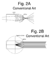
- FIG. 1 is a perspective view illustrating a vehicle lighting unit 200 described in Japanese Patent Application Laid-Open No. 2010-108639 .
- the vehicle lighting unit 200 described in Japanese Patent Application Laid-Open No. 2010-108639 is a projection type vehicle lighting unit that can include a light source 210 and a light guiding body 220.
- the light guiding body 220 can be configured by a transparent member, and include: a light incident surface 220a of a semispheric recess; a reflection surface 220b configured to reflect light entering the light guiding body 220 through the light incident surface 220a; a light exiting surface 220c configured to cause the light gathered by the reflection surface 220b to exit therethrough; an edge portion 220d; and a flat surface 220e extending from the edge portion 220d and configured to function as a reflection surface.
- a region of the flat surface 220e at or near the edge portion 220d is subjected to an anti-reflection treatment, wherein the region corresponds to the region A1 between the lines L1 and L3 and the region A2 between the lines L2 and L4 in FIG. 1 .
- the curvature of the light exiting surface 220c is decreased.
- part of light being guided through the light guiding body 220 can be internally reflected by the light exiting surface 220c to cause loss of light amount.
- the light that is internally reflected is originally allowed to exit through the light exiting surface 220c to be horizontally diffused for the illumination of right and left portions of the given light distribution pattern.
- the illuminance at the right and left portions of the light distribution pattern is disadvantageously decreased.
- the improvement of comma aberration requires the principal surface of the light exiting surface 220c near the light source 210 to coincide with (or substantially coincide with) a sphere of which center is located at the rear side focal point F 220c of the light exiting surface 220c (so-called, Apollo's circle).
- a sphere of which center is located at the rear side focal point F 220c of the light exiting surface 220c (so-called, Apollo's circle).
- the vehicle lighting unit 200 with the above configuration can generate glare light due to the comma aberration formed above the horizontal line H in the light distribution pattern as illustrated in FIG. 3 , meaning that a clear cut-off line cannot be formed.
- the region of the flat surface 220e near the edge portion 220d (the region corresponds to the region A1 between the lines L1 and L3 and the region A2 between the lines L2 and L4 in FIG. 1 ) must be subjected to an anti-reflection treatment, resulting in lowering the light utilization efficiency.
- a projection-type vehicle lighting unit can use a light guiding body, wherein it is prevented to cause light loss due to the internal reflection of light at the light exiting surface as a result of being guided through the light guiding body.
- a projection-type vehicle lighting unit can use a light guiding body, wherein the spherical aberration can be removed while improving comma aberration.
- a projection-type vehicle lighting unit can use a light guiding body, the vehicle lighting unit being capable of forming a clear cut-off line in the light distribution pattern without generating glare light caused by comma aberration above a horizontal line in the light distribution pattern and without forming a conventional anti-reflection treatment performed on a certain region of the light guiding body.
- a vehicle lighting unit can include: a light source; a projection lens having a rear side focal point; and a light guiding body configured to collect light from the light source at or near the rear side focal point of the projection lens so as to guide the light to the projection lens, wherein the light guiding body can include a first optical surface that can serve as a light exiting surface through which the light emitted from the light source and guided through the light guiding body can exit, wherein the projection lens can include at least the first optical surface, a second optical surface, and a third optical surface, and wherein the projection lens can be configured to have the rear side focal point located behind the first optical surface.
- the vehicle lighting unit that utilizes a light guiding body can prevent light loss due to the internal reflection of light, being guided through the light guiding body, at the first optical surface (or light exiting surface).
- the projection lens can include at least the first optical surface, the second optical surface, and the third optical surface to diffuse the optical power of each optical surface. This can increase the curvature of the first optical surface when compared with the case where the projection lens incudes only the first optical surface.
- the above aspect it is possible to inhibit the generation of loss of light amount due to the internal reflection of light, being guided through the light guiding body, at the first optical surface (or light exiting surface). As a result of this, the light having passed through the projection lens and projected forward can be diffused in the right and left directions. This can prevent the decrease of illuminance at the right and left portions of the light distribution pattern.
- the first optical surface, the second optical surface, and the third optical surface can be configured such that the spherical aberration of the projection lens is removed and the projection lens can have a principal surface thereof on the light source side being substantially coincide with a sphere of which center is located at or near the rear side focal point.
- the projection-type vehicle lighting unit utilizing a light guiding body can remove the spherical aberration of the projection lens and also improve the comma aberration.
- the projection lens can include at least the first optical surface, the second optical surface, and the third optical surface and the respective optical surfaces can be configured such that the spherical aberration of the projection lens can be eliminated and the principal surface of the projection lens near the light source can coincide with (or substantially coincide with) a sphere of which center is located at the rear side focal point (so-called, Apollo's circle).
- the principal surface of the projection lens can be referred as a locus drawn by intersections between extending lines of a group of light beams, which have passed through the rear side focal point of the projection lens and are incident on the first optical surface, and a group of light beams parallel to the optical axis of the vehicle lighting unit.
- the spherical aberration of the projection lens can be eliminated as well as the comma aberration can be improved.
- the vehicle lighting unit can form a clear cut-off line in the light distribution pattern without generating glare light caused by comma aberration above a horizontal line in the light distribution pattern and without forming a conventional anti-reflection treatment performed on a certain region of the light guiding body.
- the first optical surface can preferably be configured to be an optical surface having a convex curvature protruded in a light emission direction in which the light can exit through the first optical surface
- the second optical surface can preferably be configured to be an optical surface having a concave curvature recessed in the light emission direction.
- the light guiding body can include an edge portion disposed at or near the rear side focal point, for forming a cut-off line in a light distribution pattern formed by the vehicle lighting unit, and a flat portion configured to extend from the edge portion rearward.
- a light distribution pattern for example, a low-beam light distribution pattern
- a light distribution pattern including an upper edge formed by the cut-off line defined by the edge portion.
- the vehicle lighting unit can include an additional lens section having a front surface serving as the third optical surface and a rear surface serving as the second optical surface, wherein the projection lens can be configured to include the first optical surface of the light guiding body, and the second optical surface and the third optical surface of the additional lens section.
- a vehicle lighting unit can include:
- the projection-type vehicle lighting unit utilizing a light guiding body in the projection-type vehicle lighting unit utilizing a light guiding body according to the above aspect, first, it can be inhibited to cause loss of light amount due to the internal reflection of light at the light exiting surface as a result of being guided through the light guiding body. Second, in the projection-type vehicle lighting unit utilizing a light guiding body with the above configuration, the spherical aberration can be removed while improving comma aberration.
- the vehicle lighting unit can form a clear cut-off line in the light distribution pattern without generating glare light caused by comma aberration above a horizontal line in the light distribution pattern and without forming a conventional anti-reflection treatment performed on a certain region of the light guiding body.
- FIG. 4 is a perspective view illustrating a vehicle lighting unit 10 made in accordance with the principles of the present invention
- FIG. 5A is a plan view of the vehicle lighting unit 10 of FIG. 4
- FIG. 5B a front view of the same
- FIG. 5C a vertical cross-sectional view of the same.
- the vehicle lighting unit 20 in the present exemplary embodiment can be configured as a projection type vehicle lighting unit including a light guiding body 16, wherein the light guiding body can be configured to guide light from a light source 12 to a light exiting surface or a first optical surface 16c so that the light can exit through the first optical surface 16c.
- the vehicle lighting unit 20 can include the light source 12, a projection lens 14 having a rear side focal point F 14 , the light guiding body 16, and the like.
- the light source 12 can be a white light-emitting diode (LED), for example, of about 300 lm, having a light emission portion with a size of about 1 mm x about 2 mm.
- the light source 12 can be supported by a not-shown substrate fixed to the vehicle guiding body 16 while its light emission portion faces upward in the vertical direction.
- the directional characteristics of the light source 12 can be that of a Lambertial source.
- the light source 12 can be a laser diode (LD) or other light source in addition to the white LED.
- FIG. 6A and FIG. 6B are a plan view and a side view, respectively, illustrating optical paths of light emitted from the light source 12 and guided within the light guiding body 16.
- the light guiding body 16 can receive light from the light source 12 and collect the light at or near the rear side focal point F 14 of the projection lens 14 to guide the light to the first optical surface 16c (light exiting surface), thereby allowing light to exit through the first optical surface 16c.
- the light guiding body 16 can be formed from a transparent resin such as an acrylic resin (e.g., PMMA) and a polycarbonate resin (PC).
- the light guiding body 16 can include a light incident surface 16a, a flat reflection surface 16b, the first optical surface 16c (light exiting surface), and the like.
- the flat reflection surface 16b can be a total reflection surface configured to achieve total reflection.
- the light incident surface 16a can include a convex center light incident surface 16a1 and a periphery light incident surface 16a2.
- the center light incident surface 16a1 can be disposed on an optical axis AX 12 of the light source 12 in front of the light source 12.
- the center light incident surface 16a1 is convex toward the light source 12.
- the periphery light incident surface 16a2 can be configured to extend from the peripheral edge of the center light incident surface 16a1 toward the light source 12, namely, to be formed as a cylindrical surface surrounding the optical axis AX 12 of the light source 12 in front of the light source 12.
- the light incident surface 16a can further include a narrowed cylindrical reflection surface 16a3 surrounding the center light incident surface 16a1 and the periphery light incident surface 16a2 from outside.
- the light incident surface 16a (including the center light incident surface 16a1 and the periphery light incident surface 16a2) can be provided at a lower, rear end portion of the light guiding body 16 and the light source 12 can be disposed below the light incident surface 16a of the light guiding body 16, as illustrated in the drawings.
- the provision of the flat reflection surface 16b can change the optical paths of light entering the light guiding body 16. This configuration can reduce the size of the light guiding body 16 in the front-to-rear direction.
- the light emitted by the light source 12 can be incident on the center light incident surface 16a1 to enter the light guiding body 16, and can be totally reflected by the flat reflection surface 16b to be converged at or near the rear side focal point F14 of the projection lens 14.
- the center light incident surface 16a1 can be designed to receive the light from the light source 12 or a virtual point light source positioned at a reference point F and converge the most part of the light at or near the rear side focal point F14 of the projection lens 14.
- the light emitted by the light source 12 can be incident on the periphery light incident surface 16a2 to enter the light guiding body 16, and can be totally reflected by the cylindrical reflection surface 16a3 surrounding the periphery light incident surface 16a2 and then by the flat reflection surface 16b to be converged at or near the rear side focal point F14 of the projection lens 14.
- the cylindrical reflection surface 16a3 can be designed to receive the light from the light source 12 or a virtual point light source positioned at a reference point F through the periphery light incident surface 16a2 and totally reflect and converge the most part of the light at or near the rear side focal point F14 of the projection lens 14.
- the projection lens 14 can be configured to include at least the first optical surface 16c (light exiting surface), a second optical surface 18a, and a third optical surface 18b, and have the rear side focal point F 14 disposed behind the first optical surface 16c and within the light guiding body 16. Namely, the projection lens 14 can be configured to include part of the light guiding body 16 and an additional lens section 18 disposed in front of the light guiding body 16.
- the first optical surface 16c can be formed at a front end portion of the light guiding body 16.
- the first optical surface 16c can be configured to be an optical surface protruded (convex) in a light emission direction of light exiting through the first optical surface 16c and having a positive curvature.
- the first optical surface 16c can be optimized to be a polynomial aspheric lens surface having a positive radius of curvature, for example.
- the second optical surface 18a can be a rear surface of the additional lens section 18 disposed in front of the first optical surface 16c of the light guiding body 16.
- the second optical surface 18a can be configured to be an optical surface having a negative curvature (concave) in the light emission direction of light exiting through the first optical surface 16c.
- the second optical surface 18a can be configured to be a spherical surface having a negative radius of curvature of, for example, 40 mm.
- the third optical surface 18b can be a front surface of the additional lens section 18.
- the third optical surface 18b can be configured to be a flat surface having an infinite radius of curvature, for example, a flat surface perpendicular to an optical axis AX 10 of the vehicle lighting unit 10.
- the third optical surface 18b can be configured to be a convex or concave optical surface in the light emission direction in addition to the flat surface.
- the additional lens section 18 can be disposed in front of the light guiding body 16 while connected thereto with a pair of right and left connection sections 16d and 16e such that the additional lens section 18 is positioned away from the front end portion (the first optical surface 16c) of the light guiding body 16 with a predetermined gap therebetween. Accordingly, in the present exemplary embodiment, the additional lens section 18 and the light guiding body 16 can be integrally formed via the pair of connection sections 16d and 16e.
- the first optical surface 16c, the second optical surface 18a, and the third optical surface 18b can be configured to have respective surface shapes with the spherical aberration of the projection lens 14 having been eliminated.
- the principal surface of the projection lens 14 near the light source 12 can be configured to coincide with (or substantially coincide with) a sphere of which center is located at the rear side focal point F 14 of the projection lens 14 (so-called, Apollo's circle). Accordingly, the first optical surface 16c, the second optical surface 18a, and the third optical surface 18b can constitute the function of the projection lens 14 as a whole.
- the principal surface of the projection lens 14 can be a locus drawn by intersections between extending lines of a group of light beams, which have passed through the rear side focal point F 14 of the projection lens 14 and are incident on the first optical surface 16c, and a group of light beams parallel to the optical axis AX 10 of the vehicle lighting unit 10, as in FIG. 9B .
- the light guiding body 16 can further include an edge portion 16f and a flat portion 16g.
- the edge portion 16f can be provided at or near the rear side focal point F 14 of the projection lens 14 so as to form a cut-off line CL in a light distribution pattern.
- the shape of the edge portion 16f can be a curved edge shape that corresponds to the curvature of field of the projection lens 14.
- the flat portion 16g can be a total reflection surface and extend from the edge portion 16f rearward (see FIGS. 4 and 5C ).
- the light from the light source 12 can be incident on the light incident surface 16a (including the center light incident surface 16a1 and the periphery light incident surface 16a2) to enter the light guiding body 16.
- the incident light can be reflected by the cylindrical reflection surface 16a3 and the flat reflection surface 16b, and part of the light can be converged to or near the rear side focal point F 14 of the projection lens 14.
- the light having passed the rear side focal point F 14 can be guided to the first optical surface 16c to exit through the first optical surface 16c.
- Another part of the light can be directly guided to the first optical surface 16c without converged to the rear side focal point F 14 to exit through the first optical surface 16c.
- the light exiting through the first optical surface 16c can pass through the second optical surface 18a and the third optical surface 18b of the additional lens section 18 to be projected forward, thereby forming the light distribution pattern P, such as a low-beam light distribution pattern, having a clear cut-off line CL at its upper edge, the light distribution pattern being formed on a virtual vertical screen assumed to be disposed at a position in front of the vehicle lighting unit 10 about 25 meters ahead, as illustrated in FIG. 7 .
- the light distribution pattern P such as a low-beam light distribution pattern, having a clear cut-off line CL at its upper edge
- the formation of the clear cut-off line CL can be achieved by the following configurations, wherein the spherical aberration of the projection lens 14 can be eliminated; the respective optical surfaces can be configured such that the principal surface of the projection lens 14 near the light source 12 can coincide with (or substantially coincide with) a sphere of which center is located at the rear side focal point F 14 of the projection lens 14 (so-called, Apollo's circle); and the sign conditions (conditions for removing comma aberration) can be satisfied (or substantially satisfied).
- edge portion 16f can be configured to be shaped corresponding to the desired cut-off line CL that can include a left horizontal cut-off line CL1, a right horizontal cut-off line CL2, and a slanted cut-off line CL2 connecting the right and left horizontal cut-off lines CL1 and CL2, as illustrated in FIG. 7 .
- the light distribution pattern P can include a step at a road shoulder side by about 0.57 degrees on the virtual vertical screen.
- the projection-type vehicle lighting unit 10 that can use the light guiding body 16
- the light loss due to the internal reflection of light at the light exiting surface (the first optical surface 16c) as a result of being guided through the light guiding body 16 can be prevented.
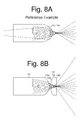
- the projection lens 14 can include at least the first optical surface 16c, the second optical surface 18a, and the third optical surface 18b to diffuse the optical power of each optical surface 16c, 18a, or 18b. (See FIG. 8B .) This can increase the curvature of the first optical surface 16c when compared with the case where the projection lens 14 incudes only the first optical surface 16c (see FIG. 8A ).
- the projection-type vehicle lighting unit 10 of the present exemplary embodiment it is possible to inhibit the generation of loss of light due to the internal reflection of light, being guided through the light guiding body 16, at the first optical surface 16c (light exiting surface). As a result of this, the light having passed through the projection lens 14 and projected forward can be diffused in the right and left directions. This can prevent the decrease of illuminance at the right and left portions of the light distribution pattern P.
- the projection-type vehicle lighting unit 10 utilizing the light guiding body 16 can remove the spherical aberration of the projection lens 14 and also improve the comma aberration.
- the projection lens 14 can include at least the first optical surface 16c, the second optical surface 18a, and the third optical surface 18b and the respective optical surfaces 16c, 18a, and 18b can be configured such that the spherical aberration of the projection lens 14 can be eliminated and the principal surface of the projection lens 14 near the light source 12 can coincide with (or substantially coincide with) a sphere of which center is located at the rear side focal point F 14 of the projection lens 14 (so-called, Apollo's circle). As illustrated in FIG.
- the first optical surface 16c cannot be configured to cause the spherical aberration of the projection lens 14 (or the first optical surface 16c) to be removed and to coincide with a sphere of which center is located at the rear side focal point F 14 of the projection lens 14 (so-called, Apollo's circle).
- the principal surface of the projection lens 14 can be a locus drawn by intersections between extending lines of a group of light beams, which have passed through the rear side focal point F 14 of the projection lens 14 and are incident on the first optical surface 16c, and a group of light beams parallel to the optical axis AX 10 of the vehicle lighting unit 10 as shown in FIG. 9A , meaning that the principal surface straightforwardly corresponds to the first optical surface 16c itself.
- the spherical aberration of the projection lens 14 can be eliminated as well as the comma aberration can be improved.
- the vehicle lighting unit 10 can form a clear cut-off line CL in the light distribution pattern P, for example, as illustrated in FIG. 7 , without generating glare light caused by comma aberration above the horizontal line H in the light distribution pattern and without forming a conventional anti-reflection treatment performed on a certain region of the light guiding body 16.
- the present exemplary embodiment has been exemplified to a vehicle lighting unit for forming the light distribution pattern P having the clear cut-off line CL at its upper edge.
- the present invention can be widely applied to various vehicle lighting units for forming various light distribution patterns, such as a high-beam light distribution pattern, a pedestrian light distribution pattern for illuminating a pedestrian side road, a signal sign light distribution pattern for illuminating a signal sign disposed above or sideward, or the like.
Landscapes
- Engineering & Computer Science (AREA)
- General Engineering & Computer Science (AREA)
- Physics & Mathematics (AREA)
- Optics & Photonics (AREA)
- General Physics & Mathematics (AREA)
- Microelectronics & Electronic Packaging (AREA)
- Non-Portable Lighting Devices Or Systems Thereof (AREA)
Applications Claiming Priority (1)
| Application Number | Priority Date | Filing Date | Title |
|---|---|---|---|
| JP2013122950A JP6131724B2 (ja) | 2013-06-11 | 2013-06-11 | 車両用灯具 |
Publications (3)
| Publication Number | Publication Date |
|---|---|
| EP2818792A2 true EP2818792A2 (de) | 2014-12-31 |
| EP2818792A3 EP2818792A3 (de) | 2015-11-18 |
| EP2818792B1 EP2818792B1 (de) | 2021-02-24 |
Family
ID=51032915
Family Applications (1)
| Application Number | Title | Priority Date | Filing Date |
|---|---|---|---|
| EP14171925.2A Active EP2818792B1 (de) | 2013-06-11 | 2014-06-11 | Fahrzeugbeleuchtungseinheit |
Country Status (3)
| Country | Link |
|---|---|
| US (1) | US9400089B2 (de) |
| EP (1) | EP2818792B1 (de) |
| JP (1) | JP6131724B2 (de) |
Cited By (18)
| Publication number | Priority date | Publication date | Assignee | Title |
|---|---|---|---|---|
| EP3109542A1 (de) * | 2015-06-17 | 2016-12-28 | Stanley Electric Co., Ltd. | Linsenkörper und fahrzeugbeleuchtungskörper |
| EP3124854A1 (de) * | 2015-07-28 | 2017-02-01 | Valeo Vision | Beleuchtungssystem für kraftfahrzeugscheinwerfer |
| EP3150905A4 (de) * | 2014-05-23 | 2017-06-21 | Stanley Electric Co., Ltd. | Linsenkörper, kombinierter linsenkörper und fahrzeuglampenfassung |
| WO2017120630A1 (de) * | 2016-01-14 | 2017-07-20 | Zkw Group Gmbh | Beleuchtungseinheit für einen kraftfahrzeugscheinwerfer zum erzeugen eines lichtbündels mit hell-dunkel-grenze |
| EP3246621A1 (de) * | 2016-05-18 | 2017-11-22 | Valeo Vision | Diopter mit unterbrechungsausgleich |
| EP3246620A1 (de) * | 2016-05-18 | 2017-11-22 | Valeo Vision | Led-scheinwerfer für fahrzeuge mit diopter, der eine abschattung erzeugt |
| ITUA20164515A1 (it) * | 2016-06-20 | 2017-12-20 | Automotive Lighting Italia Spa | Dispositivo compatto di illuminazione per veicoli |
| FR3056691A1 (fr) * | 2016-09-29 | 2018-03-30 | Valeo Vision | Module optique pour projecteur de vehicule automobile dote d'une fonction d'eclairage adaptatif, comportant un systeme optique de renvoi du faisceau lumineux projete |
| EP3382263A4 (de) * | 2016-09-30 | 2019-03-27 | H.A. Automotive Systems, Inc. | Kondensator für abblendlichtmodul eines fahrzeugs |
| CN109958958A (zh) * | 2017-12-14 | 2019-07-02 | Sl株式会社 | 车辆用灯具 |
| WO2020064978A1 (en) * | 2018-09-27 | 2020-04-02 | Valeo Vision | Optical element, optical module, and vehicle |
| EP3671016A1 (de) * | 2018-12-21 | 2020-06-24 | ZKW Group GmbH | Beleuchtungsvorrichtung für einen kraftfahrzeugscheinwerfer sowie kraftfahrzeugscheinwerfer |
| WO2020232956A1 (zh) * | 2019-05-17 | 2020-11-26 | 华域视觉科技(上海)有限公司 | 一种导光元件、车辆照明装置及汽车 |
| EP3885644A4 (de) * | 2020-01-20 | 2021-10-27 | Hasco Vision Technology Co., Ltd. | Optisches abblendlichtmodul, abblendlichtbeleuchtungsmodul, fahrzeugleuchte und fahrzeug |
| EP3628915B1 (de) * | 2018-09-28 | 2022-06-29 | Valeo Vision | Optisches monoblockteil aus durchsichtigem oder lichtdurchlässigem material mit inaktiver oberfläche, die einen lichtstreuenden abschnitt umfasst |
| EP3167226B1 (de) * | 2014-07-11 | 2022-08-31 | Valeo Vision | Beleuchtungsmodul für ein kraftfahrzeug |
| US20240310014A1 (en) * | 2022-07-13 | 2024-09-19 | Hyundai Mobis Co., Ltd. | Lamp module for vehicle and lamp for vehicle including the same |
| EP3499113B1 (de) * | 2017-12-14 | 2026-01-21 | Valeo North America, Inc. | Lichtleiter-vorrichtung zur kfz-beleuchtung |
Families Citing this family (24)
| Publication number | Priority date | Publication date | Assignee | Title |
|---|---|---|---|---|
| CN106471309B (zh) * | 2014-07-08 | 2019-04-23 | 三菱电机株式会社 | 前照灯模块 |
| US10760760B2 (en) | 2015-09-15 | 2020-09-01 | SMR Patents S.à.r.l. | Illumination apparatus, vehicle component and vehicle |
| DE202015104894U1 (de) | 2015-09-15 | 2015-09-25 | SMR Patents S.à.r.l. | Beleuchtungseinrichtung, Fahrzeugkomponente und Fahrzeug |
| JP6659305B2 (ja) * | 2015-10-27 | 2020-03-04 | スタンレー電気株式会社 | レンズ体、レンズ結合体及び車両用灯具 |
| CN108603644B (zh) * | 2016-01-13 | 2020-11-06 | 三菱电机株式会社 | 前照灯模块和前照灯装置 |
| ITUA20164809A1 (it) * | 2016-06-30 | 2017-12-30 | Automotive Lighting Italia Spa | Fanale automobilistico comprendente una porzione di emissione luminosa ad effetto opalescente |
| JP6671012B2 (ja) | 2016-07-15 | 2020-03-25 | パナソニックIpマネジメント株式会社 | 車両用前照灯 |
| KR102405436B1 (ko) * | 2017-09-28 | 2022-06-07 | 에스엘 주식회사 | 차량용 램프 |
| JP7002046B2 (ja) | 2017-12-25 | 2022-02-04 | パナソニックIpマネジメント株式会社 | 車両用前照灯 |
| US11226078B2 (en) * | 2018-04-23 | 2022-01-18 | Stanley Electric Co., Ltd. | Vehicular lamp fitting |
| EP3650933B1 (de) | 2018-11-06 | 2025-01-01 | SMR Patents S.à.r.l. | Beleuchtungsvorrichtung, fahrzeugkomponente und fahrzeug |
| KR102555372B1 (ko) * | 2018-11-19 | 2023-07-13 | 에스엘 주식회사 | 차량용 램프 |
| KR102558734B1 (ko) * | 2018-12-26 | 2023-07-25 | 에스엘 주식회사 | 차량용 램프 |
| KR102757872B1 (ko) * | 2019-06-13 | 2025-01-21 | 현대자동차주식회사 | 차량용 슬림형 램프장치 |
| FR3097979B1 (fr) * | 2019-06-28 | 2021-06-11 | Valeo Vision | Pièce optique destinée à fonctionner en réflexion interne totale |
| WO2021085298A1 (ja) * | 2019-11-01 | 2021-05-06 | 市光工業株式会社 | 車両用導光体及び車両用前照灯 |
| JP2021072254A (ja) * | 2019-11-01 | 2021-05-06 | 市光工業株式会社 | 車両用導光体及び車両用前照灯 |
| JP7459481B2 (ja) * | 2019-11-01 | 2024-04-02 | 市光工業株式会社 | 車両用導光体及び車両用前照灯 |
| JP7424169B2 (ja) * | 2020-03-31 | 2024-01-30 | 市光工業株式会社 | 車両用導光体及び車両用灯具ユニット |
| JP7472618B2 (ja) * | 2020-04-16 | 2024-04-23 | 市光工業株式会社 | 車両用導光体及び車両用灯具ユニット |
| WO2022044078A1 (ja) * | 2020-08-24 | 2022-03-03 | 三菱電機株式会社 | 前照灯モジュール及び前照灯装置 |
| KR20250021856A (ko) * | 2023-08-07 | 2025-02-14 | 현대모비스 주식회사 | 램프 |
| FR3162074A1 (fr) * | 2024-08-30 | 2025-11-14 | Valeo Vision | Module optique comportant une source lumineuse et une pièce optique monobloc |
| CN119879118B (zh) * | 2025-03-28 | 2025-07-08 | 华域视觉科技(常熟)有限公司 | 车灯模组及车灯 |
Citations (1)
| Publication number | Priority date | Publication date | Assignee | Title |
|---|---|---|---|---|
| JP2010108639A (ja) | 2008-10-28 | 2010-05-13 | Stanley Electric Co Ltd | 車両用灯具、及び、レンズ体 |
Family Cites Families (15)
| Publication number | Priority date | Publication date | Assignee | Title |
|---|---|---|---|---|
| DE1165514B (de) * | 1957-09-20 | 1964-03-19 | Akad Wissenschaften Ddr | Axialsymmetrische Sammellinse |
| JPH0560970A (ja) * | 1991-08-30 | 1993-03-12 | Hoya Corp | 2群2枚構成の非球面レンズ系 |
| DE102005017528A1 (de) * | 2004-08-27 | 2006-03-09 | Osram Opto Semiconductors Gmbh | Leuchtmittel mit vorgegebener Abstrahlcharakteristik und Primäroptikelement für ein Leuchtmittel |
| JP2006164858A (ja) * | 2004-12-09 | 2006-06-22 | Koito Mfg Co Ltd | 車両用照明灯具 |
| FR2884899B1 (fr) * | 2005-04-21 | 2007-06-15 | Valeo Vision Sa | Module d'eclairage donnant un faisceau lumineux avec coupure pour projecteur de vehicule automobile, et projecteur comprenant un tel module |
| DE102006044641A1 (de) * | 2006-09-19 | 2008-03-27 | Schefenacker Vision Systems Germany Gmbh | Leuchteinheit mit Leuchtdiode, Lichtleitkörper und Sekundärlinse |
| JP4863216B2 (ja) * | 2007-03-09 | 2012-01-25 | スタンレー電気株式会社 | プロジェクター型ヘッドライト用の投影レンズ |
| US8408721B2 (en) * | 2008-08-14 | 2013-04-02 | 3M Innovative Properties Company | Projection system with imaging light source module |
| JP2010170836A (ja) * | 2009-01-22 | 2010-08-05 | Stanley Electric Co Ltd | プロジェクタ型車両用前照灯 |
| JP5443905B2 (ja) * | 2009-09-03 | 2014-03-19 | リコー光学株式会社 | 照射方向可変前照灯および投射レンズ |
| DE102010023360A1 (de) * | 2009-10-05 | 2011-04-07 | Automotive Lighting Reutlingen Gmbh | Zur Erzeugung verschiedener Lichtverteilungen eingerichteter Kraftfahrzeugscheinwerfer mit Halbleiterlichtquellen |
| WO2012072190A2 (de) * | 2010-12-03 | 2012-06-07 | Docter Optics Gmbh | Optisches bauteil für beleuchtungszwecke |
| WO2013014046A1 (en) * | 2011-07-25 | 2013-01-31 | Osram Ag | A light source, for example for lighting surfaces |
| EP2587120B1 (de) * | 2011-10-27 | 2016-04-13 | odelo GmbH | Lichtleiterelement und Kraftfahrzeugleuchte mit einem Lichtleiterelement |
| JP5911397B2 (ja) * | 2012-07-31 | 2016-04-27 | スタンレー電気株式会社 | 車両用前照灯 |
-
2013
- 2013-06-11 JP JP2013122950A patent/JP6131724B2/ja active Active
-
2014
- 2014-06-11 EP EP14171925.2A patent/EP2818792B1/de active Active
- 2014-06-11 US US14/301,687 patent/US9400089B2/en active Active
Patent Citations (2)
| Publication number | Priority date | Publication date | Assignee | Title |
|---|---|---|---|---|
| JP2010108639A (ja) | 2008-10-28 | 2010-05-13 | Stanley Electric Co Ltd | 車両用灯具、及び、レンズ体 |
| JP5196314B2 (ja) | 2008-10-28 | 2013-05-15 | スタンレー電気株式会社 | 車両用灯具、及び、レンズ体 |
Cited By (37)
| Publication number | Priority date | Publication date | Assignee | Title |
|---|---|---|---|---|
| US11009210B2 (en) | 2014-05-23 | 2021-05-18 | Stanley Electric Co., Ltd. | Vehicle lamp lens body, combined lens body with two serial condensing lens body |
| EP3150905A4 (de) * | 2014-05-23 | 2017-06-21 | Stanley Electric Co., Ltd. | Linsenkörper, kombinierter linsenkörper und fahrzeuglampenfassung |
| US10352523B2 (en) | 2014-05-23 | 2019-07-16 | Stanley Electric Co., Ltd. | Vehicle lamp lens body, combined lens body with semicircular cylindrical output surfaces |
| EP3167226B1 (de) * | 2014-07-11 | 2022-08-31 | Valeo Vision | Beleuchtungsmodul für ein kraftfahrzeug |
| US10072812B2 (en) | 2015-06-17 | 2018-09-11 | Stanley Electric Co., Ltd. | Lens body and vehicle lighting fixture |
| EP3109542A1 (de) * | 2015-06-17 | 2016-12-28 | Stanley Electric Co., Ltd. | Linsenkörper und fahrzeugbeleuchtungskörper |
| EP3124854A1 (de) * | 2015-07-28 | 2017-02-01 | Valeo Vision | Beleuchtungssystem für kraftfahrzeugscheinwerfer |
| FR3039630A1 (fr) * | 2015-07-28 | 2017-02-03 | Valeo Vision | Systeme d'eclairage pour projecteur de vehicule automobile |
| US11156333B2 (en) | 2015-07-28 | 2021-10-26 | Valeo Vision | Lighting system for motor vehicle headlight |
| US11892133B2 (en) | 2015-07-28 | 2024-02-06 | Valeo Vision | Lighting system for motor vehicle headlight |
| EP3415810A1 (de) * | 2015-07-28 | 2018-12-19 | Valeo Vision | Beleuchtungssystem für kraftfahrzeugscheinwerfer |
| US10151437B2 (en) | 2015-07-28 | 2018-12-11 | Valeo Vision | Lighting system for motor vehicle headlight |
| WO2017120630A1 (de) * | 2016-01-14 | 2017-07-20 | Zkw Group Gmbh | Beleuchtungseinheit für einen kraftfahrzeugscheinwerfer zum erzeugen eines lichtbündels mit hell-dunkel-grenze |
| EP3246620A1 (de) * | 2016-05-18 | 2017-11-22 | Valeo Vision | Led-scheinwerfer für fahrzeuge mit diopter, der eine abschattung erzeugt |
| US10161592B2 (en) | 2016-05-18 | 2018-12-25 | Valeo Vision | LED headlamp with refractive interface creating cut-off for vehicles |
| FR3051541A1 (fr) * | 2016-05-18 | 2017-11-24 | Valeo Vision | Projecteur a led a dioptre creant coupure pour vehicules |
| FR3051537A1 (fr) * | 2016-05-18 | 2017-11-24 | Valeo Vision | Dioptre redresseur de coupure |
| EP3246621A1 (de) * | 2016-05-18 | 2017-11-22 | Valeo Vision | Diopter mit unterbrechungsausgleich |
| CN107525002A (zh) * | 2016-06-20 | 2017-12-29 | 意大利汽车照明股份公司 | 用于车辆的紧凑的照明装置 |
| EP3260764A1 (de) * | 2016-06-20 | 2017-12-27 | Automotive Lighting Italia S.p.A. | Kompakte beleuchtungsvorrichtung für fahrzeuge |
| ITUA20164515A1 (it) * | 2016-06-20 | 2017-12-20 | Automotive Lighting Italia Spa | Dispositivo compatto di illuminazione per veicoli |
| FR3056691A1 (fr) * | 2016-09-29 | 2018-03-30 | Valeo Vision | Module optique pour projecteur de vehicule automobile dote d'une fonction d'eclairage adaptatif, comportant un systeme optique de renvoi du faisceau lumineux projete |
| EP3382263A4 (de) * | 2016-09-30 | 2019-03-27 | H.A. Automotive Systems, Inc. | Kondensator für abblendlichtmodul eines fahrzeugs |
| EP3663637A1 (de) * | 2016-09-30 | 2020-06-10 | H.A. Automotive Systems, Inc. | Kondensator für abblendlichtmodul eines fahrzeugs |
| EP3667161A1 (de) * | 2016-09-30 | 2020-06-17 | H.A. Automotive Systems, Inc. | Kondensator für abblendlichtmodul eines fahrzeugs |
| CN109958958A (zh) * | 2017-12-14 | 2019-07-02 | Sl株式会社 | 车辆用灯具 |
| EP3499113B1 (de) * | 2017-12-14 | 2026-01-21 | Valeo North America, Inc. | Lichtleiter-vorrichtung zur kfz-beleuchtung |
| WO2020064978A1 (en) * | 2018-09-27 | 2020-04-02 | Valeo Vision | Optical element, optical module, and vehicle |
| EP3628915B1 (de) * | 2018-09-28 | 2022-06-29 | Valeo Vision | Optisches monoblockteil aus durchsichtigem oder lichtdurchlässigem material mit inaktiver oberfläche, die einen lichtstreuenden abschnitt umfasst |
| KR20210094622A (ko) * | 2018-12-21 | 2021-07-29 | 제트카베 그룹 게엠베하 | 자동차 헤드램프용 조명 장치와 자동차 헤드램프 |
| WO2020126350A1 (de) * | 2018-12-21 | 2020-06-25 | Zkw Group Gmbh | Beleuchtungsvorrichtung für einen kraftfahrzeugscheinwerfer sowie kraftfahrzeugscheinwerfer |
| EP3671016A1 (de) * | 2018-12-21 | 2020-06-24 | ZKW Group GmbH | Beleuchtungsvorrichtung für einen kraftfahrzeugscheinwerfer sowie kraftfahrzeugscheinwerfer |
| WO2020232956A1 (zh) * | 2019-05-17 | 2020-11-26 | 华域视觉科技(上海)有限公司 | 一种导光元件、车辆照明装置及汽车 |
| EP3885644A4 (de) * | 2020-01-20 | 2021-10-27 | Hasco Vision Technology Co., Ltd. | Optisches abblendlichtmodul, abblendlichtbeleuchtungsmodul, fahrzeugleuchte und fahrzeug |
| US11731552B2 (en) | 2020-01-20 | 2023-08-22 | Hasco Vision Technology Co., Ltd. | Low beam optical module, low beam illumination module, vehicle lamp and vehicle |
| US20240310014A1 (en) * | 2022-07-13 | 2024-09-19 | Hyundai Mobis Co., Ltd. | Lamp module for vehicle and lamp for vehicle including the same |
| US12359787B2 (en) * | 2022-07-13 | 2025-07-15 | Hyundai Mobis Co., Ltd. | Lamp module for vehicle and lamp for vehicle including the same |
Also Published As
| Publication number | Publication date |
|---|---|
| EP2818792A3 (de) | 2015-11-18 |
| US9400089B2 (en) | 2016-07-26 |
| EP2818792B1 (de) | 2021-02-24 |
| US20140362596A1 (en) | 2014-12-11 |
| JP6131724B2 (ja) | 2017-05-24 |
| JP2014241220A (ja) | 2014-12-25 |
Similar Documents
| Publication | Publication Date | Title |
|---|---|---|
| EP2818792B1 (de) | Fahrzeugbeleuchtungseinheit | |
| EP3333477B1 (de) | Linsenkörper, beleuchtungsvorrichtung für fahrzeug | |
| KR20240024155A (ko) | 자동차 전조등용 조명 시스템 | |
| EP2993392B1 (de) | Linsenelement und fahrzeugbeleuchtungseinheit | |
| CN101285561B (zh) | 车辆用灯具单元 | |
| EP2105655B1 (de) | Fahrzeuglampe | |
| CN108980774B (zh) | 照明装置以及车辆用前照灯 | |
| EP2767750A2 (de) | Fahrzeugscheinwerfer | |
| KR102293083B1 (ko) | 자동차 헤드램프용 조명 장치 및 자동차 헤드램프 | |
| EP2503224B1 (de) | Fahrzeugbeleuchtungseinheit | |
| JP2017212037A (ja) | 車両用前照灯 | |
| CN103807715B (zh) | 用于机动车前大灯的光模块 | |
| US10677406B2 (en) | Vehicular lamp | |
| EP3467373A1 (de) | Fahrzeugscheinwerfer und fahrzeug damit | |
| KR20230024140A (ko) | 차량용 램프 및 그 램프를 포함하는 차량 | |
| JP2022515178A (ja) | 自動車前照灯用照明装置及び自動車前照灯 | |
| KR20110036269A (ko) | 측방 조사용 프로젝션 렌즈 및 이를 장착한 헤드램프 | |
| EP3135989A1 (de) | Fahrzeug lichtleiter und fahrzeuglampe | |
| KR20150051672A (ko) | 차량용 램프 | |
| JP6659305B2 (ja) | レンズ体、レンズ結合体及び車両用灯具 | |
| JP2011187162A (ja) | 車両用灯具 | |
| KR20240155642A (ko) | 차량용 램프 | |
| CN108916805B (zh) | 车灯透镜 | |
| US11885473B2 (en) | Vehicle lamp having a light source unit with chip laterally spaced from optical axis of optical unit and a reflector central axis tilted with respect to the optical axis | |
| TWI489058B (zh) | 車用照明裝置 |
Legal Events
| Date | Code | Title | Description |
|---|---|---|---|
| PUAI | Public reference made under article 153(3) epc to a published international application that has entered the european phase |
Free format text: ORIGINAL CODE: 0009012 |
|
| 17P | Request for examination filed |
Effective date: 20140611 |
|
| AK | Designated contracting states |
Kind code of ref document: A2 Designated state(s): AL AT BE BG CH CY CZ DE DK EE ES FI FR GB GR HR HU IE IS IT LI LT LU LV MC MK MT NL NO PL PT RO RS SE SI SK SM TR |
|
| AX | Request for extension of the european patent |
Extension state: BA ME |
|
| PUAL | Search report despatched |
Free format text: ORIGINAL CODE: 0009013 |
|
| AK | Designated contracting states |
Kind code of ref document: A3 Designated state(s): AL AT BE BG CH CY CZ DE DK EE ES FI FR GB GR HR HU IE IS IT LI LT LU LV MC MK MT NL NO PL PT RO RS SE SI SK SM TR |
|
| AX | Request for extension of the european patent |
Extension state: BA ME |
|
| RIC1 | Information provided on ipc code assigned before grant |
Ipc: F21V 7/00 20060101ALI20151013BHEP Ipc: F21S 8/10 20060101AFI20151013BHEP Ipc: F21V 5/00 20150101ALI20151013BHEP Ipc: G02B 19/00 20060101ALI20151013BHEP Ipc: F21Y 101/02 20060101ALI20151013BHEP Ipc: F21V 5/04 20060101ALI20151013BHEP |
|
| R17P | Request for examination filed (corrected) |
Effective date: 20160517 |
|
| RBV | Designated contracting states (corrected) |
Designated state(s): AL AT BE BG CH CY CZ DE DK EE ES FI FR GB GR HR HU IE IS IT LI LT LU LV MC MK MT NL NO PL PT RO RS SE SI SK SM TR |
|
| STAA | Information on the status of an ep patent application or granted ep patent |
Free format text: STATUS: EXAMINATION IS IN PROGRESS |
|
| 17Q | First examination report despatched |
Effective date: 20200310 |
|
| REG | Reference to a national code |
Ref country code: DE Ref legal event code: R079 Ref document number: 602014075068 Country of ref document: DE Free format text: PREVIOUS MAIN CLASS: F21S0008100000 Ipc: F21V0005000000 |
|
| GRAP | Despatch of communication of intention to grant a patent |
Free format text: ORIGINAL CODE: EPIDOSNIGR1 |
|
| STAA | Information on the status of an ep patent application or granted ep patent |
Free format text: STATUS: GRANT OF PATENT IS INTENDED |
|
| RIC1 | Information provided on ipc code assigned before grant |
Ipc: G02B 19/00 20060101ALI20200821BHEP Ipc: F21V 5/04 20060101ALI20200821BHEP Ipc: F21S 41/27 20180101ALI20200821BHEP Ipc: F21S 41/26 20180101ALI20200821BHEP Ipc: F21S 41/16 20180101ALI20200821BHEP Ipc: F21S 41/148 20180101ALI20200821BHEP Ipc: F21S 41/365 20180101ALI20200821BHEP Ipc: F21S 41/24 20180101ALI20200821BHEP Ipc: F21S 41/265 20180101ALI20200821BHEP Ipc: F21V 5/00 20180101AFI20200821BHEP Ipc: F21V 7/00 20060101ALI20200821BHEP Ipc: F21S 41/32 20180101ALI20200821BHEP |
|
| INTG | Intention to grant announced |
Effective date: 20200915 |
|
| RAP1 | Party data changed (applicant data changed or rights of an application transferred) |
Owner name: STANLEY ELECTRIC CO., LTD. |
|
| GRAS | Grant fee paid |
Free format text: ORIGINAL CODE: EPIDOSNIGR3 |
|
| GRAA | (expected) grant |
Free format text: ORIGINAL CODE: 0009210 |
|
| STAA | Information on the status of an ep patent application or granted ep patent |
Free format text: STATUS: THE PATENT HAS BEEN GRANTED |
|
| AK | Designated contracting states |
Kind code of ref document: B1 Designated state(s): AL AT BE BG CH CY CZ DE DK EE ES FI FR GB GR HR HU IE IS IT LI LT LU LV MC MK MT NL NO PL PT RO RS SE SI SK SM TR |
|
| REG | Reference to a national code |
Ref country code: GB Ref legal event code: FG4D |
|
| REG | Reference to a national code |
Ref country code: CH Ref legal event code: EP |
|
| REG | Reference to a national code |
Ref country code: DE Ref legal event code: R096 Ref document number: 602014075068 Country of ref document: DE |
|
| REG | Reference to a national code |
Ref country code: AT Ref legal event code: REF Ref document number: 1364905 Country of ref document: AT Kind code of ref document: T Effective date: 20210315 |
|
| REG | Reference to a national code |
Ref country code: IE Ref legal event code: FG4D |
|
| REG | Reference to a national code |
Ref country code: LT Ref legal event code: MG9D |
|
| REG | Reference to a national code |
Ref country code: NL Ref legal event code: MP Effective date: 20210224 |
|
| PG25 | Lapsed in a contracting state [announced via postgrant information from national office to epo] |
Ref country code: GR Free format text: LAPSE BECAUSE OF FAILURE TO SUBMIT A TRANSLATION OF THE DESCRIPTION OR TO PAY THE FEE WITHIN THE PRESCRIBED TIME-LIMIT Effective date: 20210525 Ref country code: FI Free format text: LAPSE BECAUSE OF FAILURE TO SUBMIT A TRANSLATION OF THE DESCRIPTION OR TO PAY THE FEE WITHIN THE PRESCRIBED TIME-LIMIT Effective date: 20210224 Ref country code: HR Free format text: LAPSE BECAUSE OF FAILURE TO SUBMIT A TRANSLATION OF THE DESCRIPTION OR TO PAY THE FEE WITHIN THE PRESCRIBED TIME-LIMIT Effective date: 20210224 Ref country code: LT Free format text: LAPSE BECAUSE OF FAILURE TO SUBMIT A TRANSLATION OF THE DESCRIPTION OR TO PAY THE FEE WITHIN THE PRESCRIBED TIME-LIMIT Effective date: 20210224 Ref country code: PT Free format text: LAPSE BECAUSE OF FAILURE TO SUBMIT A TRANSLATION OF THE DESCRIPTION OR TO PAY THE FEE WITHIN THE PRESCRIBED TIME-LIMIT Effective date: 20210624 Ref country code: BG Free format text: LAPSE BECAUSE OF FAILURE TO SUBMIT A TRANSLATION OF THE DESCRIPTION OR TO PAY THE FEE WITHIN THE PRESCRIBED TIME-LIMIT Effective date: 20210524 Ref country code: NO Free format text: LAPSE BECAUSE OF FAILURE TO SUBMIT A TRANSLATION OF THE DESCRIPTION OR TO PAY THE FEE WITHIN THE PRESCRIBED TIME-LIMIT Effective date: 20210524 |
|
| REG | Reference to a national code |
Ref country code: AT Ref legal event code: MK05 Ref document number: 1364905 Country of ref document: AT Kind code of ref document: T Effective date: 20210224 |
|
| PG25 | Lapsed in a contracting state [announced via postgrant information from national office to epo] |
Ref country code: SE Free format text: LAPSE BECAUSE OF FAILURE TO SUBMIT A TRANSLATION OF THE DESCRIPTION OR TO PAY THE FEE WITHIN THE PRESCRIBED TIME-LIMIT Effective date: 20210224 Ref country code: RS Free format text: LAPSE BECAUSE OF FAILURE TO SUBMIT A TRANSLATION OF THE DESCRIPTION OR TO PAY THE FEE WITHIN THE PRESCRIBED TIME-LIMIT Effective date: 20210224 Ref country code: LV Free format text: LAPSE BECAUSE OF FAILURE TO SUBMIT A TRANSLATION OF THE DESCRIPTION OR TO PAY THE FEE WITHIN THE PRESCRIBED TIME-LIMIT Effective date: 20210224 Ref country code: NL Free format text: LAPSE BECAUSE OF FAILURE TO SUBMIT A TRANSLATION OF THE DESCRIPTION OR TO PAY THE FEE WITHIN THE PRESCRIBED TIME-LIMIT Effective date: 20210224 Ref country code: PL Free format text: LAPSE BECAUSE OF FAILURE TO SUBMIT A TRANSLATION OF THE DESCRIPTION OR TO PAY THE FEE WITHIN THE PRESCRIBED TIME-LIMIT Effective date: 20210224 |
|
| PG25 | Lapsed in a contracting state [announced via postgrant information from national office to epo] |
Ref country code: IS Free format text: LAPSE BECAUSE OF FAILURE TO SUBMIT A TRANSLATION OF THE DESCRIPTION OR TO PAY THE FEE WITHIN THE PRESCRIBED TIME-LIMIT Effective date: 20210624 |
|
| PG25 | Lapsed in a contracting state [announced via postgrant information from national office to epo] |
Ref country code: SM Free format text: LAPSE BECAUSE OF FAILURE TO SUBMIT A TRANSLATION OF THE DESCRIPTION OR TO PAY THE FEE WITHIN THE PRESCRIBED TIME-LIMIT Effective date: 20210224 Ref country code: EE Free format text: LAPSE BECAUSE OF FAILURE TO SUBMIT A TRANSLATION OF THE DESCRIPTION OR TO PAY THE FEE WITHIN THE PRESCRIBED TIME-LIMIT Effective date: 20210224 Ref country code: CZ Free format text: LAPSE BECAUSE OF FAILURE TO SUBMIT A TRANSLATION OF THE DESCRIPTION OR TO PAY THE FEE WITHIN THE PRESCRIBED TIME-LIMIT Effective date: 20210224 Ref country code: AT Free format text: LAPSE BECAUSE OF FAILURE TO SUBMIT A TRANSLATION OF THE DESCRIPTION OR TO PAY THE FEE WITHIN THE PRESCRIBED TIME-LIMIT Effective date: 20210224 |
|
| REG | Reference to a national code |
Ref country code: DE Ref legal event code: R097 Ref document number: 602014075068 Country of ref document: DE |
|
| PG25 | Lapsed in a contracting state [announced via postgrant information from national office to epo] |
Ref country code: ES Free format text: LAPSE BECAUSE OF FAILURE TO SUBMIT A TRANSLATION OF THE DESCRIPTION OR TO PAY THE FEE WITHIN THE PRESCRIBED TIME-LIMIT Effective date: 20210224 Ref country code: DK Free format text: LAPSE BECAUSE OF FAILURE TO SUBMIT A TRANSLATION OF THE DESCRIPTION OR TO PAY THE FEE WITHIN THE PRESCRIBED TIME-LIMIT Effective date: 20210224 Ref country code: RO Free format text: LAPSE BECAUSE OF FAILURE TO SUBMIT A TRANSLATION OF THE DESCRIPTION OR TO PAY THE FEE WITHIN THE PRESCRIBED TIME-LIMIT Effective date: 20210224 Ref country code: SK Free format text: LAPSE BECAUSE OF FAILURE TO SUBMIT A TRANSLATION OF THE DESCRIPTION OR TO PAY THE FEE WITHIN THE PRESCRIBED TIME-LIMIT Effective date: 20210224 |
|
| PLBE | No opposition filed within time limit |
Free format text: ORIGINAL CODE: 0009261 |
|
| STAA | Information on the status of an ep patent application or granted ep patent |
Free format text: STATUS: NO OPPOSITION FILED WITHIN TIME LIMIT |
|
| PG25 | Lapsed in a contracting state [announced via postgrant information from national office to epo] |
Ref country code: MC Free format text: LAPSE BECAUSE OF FAILURE TO SUBMIT A TRANSLATION OF THE DESCRIPTION OR TO PAY THE FEE WITHIN THE PRESCRIBED TIME-LIMIT Effective date: 20210224 Ref country code: AL Free format text: LAPSE BECAUSE OF FAILURE TO SUBMIT A TRANSLATION OF THE DESCRIPTION OR TO PAY THE FEE WITHIN THE PRESCRIBED TIME-LIMIT Effective date: 20210224 |
|
| REG | Reference to a national code |
Ref country code: CH Ref legal event code: PL |
|
| 26N | No opposition filed |
Effective date: 20211125 |
|
| PG25 | Lapsed in a contracting state [announced via postgrant information from national office to epo] |
Ref country code: SI Free format text: LAPSE BECAUSE OF FAILURE TO SUBMIT A TRANSLATION OF THE DESCRIPTION OR TO PAY THE FEE WITHIN THE PRESCRIBED TIME-LIMIT Effective date: 20210224 |
|
| REG | Reference to a national code |
Ref country code: BE Ref legal event code: MM Effective date: 20210630 |
|
| PG25 | Lapsed in a contracting state [announced via postgrant information from national office to epo] |
Ref country code: LU Free format text: LAPSE BECAUSE OF NON-PAYMENT OF DUE FEES Effective date: 20210611 |
|
| PG25 | Lapsed in a contracting state [announced via postgrant information from national office to epo] |
Ref country code: LI Free format text: LAPSE BECAUSE OF NON-PAYMENT OF DUE FEES Effective date: 20210630 Ref country code: IT Free format text: LAPSE BECAUSE OF FAILURE TO SUBMIT A TRANSLATION OF THE DESCRIPTION OR TO PAY THE FEE WITHIN THE PRESCRIBED TIME-LIMIT Effective date: 20210224 Ref country code: IE Free format text: LAPSE BECAUSE OF NON-PAYMENT OF DUE FEES Effective date: 20210611 Ref country code: CH Free format text: LAPSE BECAUSE OF NON-PAYMENT OF DUE FEES Effective date: 20210630 |
|
| PG25 | Lapsed in a contracting state [announced via postgrant information from national office to epo] |
Ref country code: IS Free format text: LAPSE BECAUSE OF FAILURE TO SUBMIT A TRANSLATION OF THE DESCRIPTION OR TO PAY THE FEE WITHIN THE PRESCRIBED TIME-LIMIT Effective date: 20210624 |
|
| PG25 | Lapsed in a contracting state [announced via postgrant information from national office to epo] |
Ref country code: BE Free format text: LAPSE BECAUSE OF NON-PAYMENT OF DUE FEES Effective date: 20210630 |
|
| PG25 | Lapsed in a contracting state [announced via postgrant information from national office to epo] |
Ref country code: HU Free format text: LAPSE BECAUSE OF FAILURE TO SUBMIT A TRANSLATION OF THE DESCRIPTION OR TO PAY THE FEE WITHIN THE PRESCRIBED TIME-LIMIT; INVALID AB INITIO Effective date: 20140611 |
|
| PG25 | Lapsed in a contracting state [announced via postgrant information from national office to epo] |
Ref country code: CY Free format text: LAPSE BECAUSE OF FAILURE TO SUBMIT A TRANSLATION OF THE DESCRIPTION OR TO PAY THE FEE WITHIN THE PRESCRIBED TIME-LIMIT Effective date: 20210224 |
|
| PG25 | Lapsed in a contracting state [announced via postgrant information from national office to epo] |
Ref country code: MK Free format text: LAPSE BECAUSE OF FAILURE TO SUBMIT A TRANSLATION OF THE DESCRIPTION OR TO PAY THE FEE WITHIN THE PRESCRIBED TIME-LIMIT Effective date: 20210224 |
|
| PGFP | Annual fee paid to national office [announced via postgrant information from national office to epo] |
Ref country code: GB Payment date: 20240502 Year of fee payment: 11 |
|
| PGFP | Annual fee paid to national office [announced via postgrant information from national office to epo] |
Ref country code: FR Payment date: 20240509 Year of fee payment: 11 |
|
| PG25 | Lapsed in a contracting state [announced via postgrant information from national office to epo] |
Ref country code: MT Free format text: LAPSE BECAUSE OF FAILURE TO SUBMIT A TRANSLATION OF THE DESCRIPTION OR TO PAY THE FEE WITHIN THE PRESCRIBED TIME-LIMIT Effective date: 20210224 |
|
| PGFP | Annual fee paid to national office [announced via postgrant information from national office to epo] |
Ref country code: DE Payment date: 20250429 Year of fee payment: 12 |
|
| PG25 | Lapsed in a contracting state [announced via postgrant information from national office to epo] |
Ref country code: TR Free format text: LAPSE BECAUSE OF FAILURE TO SUBMIT A TRANSLATION OF THE DESCRIPTION OR TO PAY THE FEE WITHIN THE PRESCRIBED TIME-LIMIT Effective date: 20210224 |
|
| GBPC | Gb: european patent ceased through non-payment of renewal fee |
Effective date: 20250611 |
|
| PG25 | Lapsed in a contracting state [announced via postgrant information from national office to epo] |
Ref country code: GB Free format text: LAPSE BECAUSE OF NON-PAYMENT OF DUE FEES Effective date: 20250611 |
|
| PG25 | Lapsed in a contracting state [announced via postgrant information from national office to epo] |
Ref country code: FR Free format text: LAPSE BECAUSE OF NON-PAYMENT OF DUE FEES Effective date: 20250630 |