EP2818802B1 - Dachentlüftungsvorrichtung aus einem mineralischen Werkstoff, insbesondere Ton - Google Patents
Dachentlüftungsvorrichtung aus einem mineralischen Werkstoff, insbesondere Ton Download PDFInfo
- Publication number
- EP2818802B1 EP2818802B1 EP14171086.3A EP14171086A EP2818802B1 EP 2818802 B1 EP2818802 B1 EP 2818802B1 EP 14171086 A EP14171086 A EP 14171086A EP 2818802 B1 EP2818802 B1 EP 2818802B1
- Authority
- EP
- European Patent Office
- Prior art keywords
- roof
- hood
- cap
- ventilation pipe
- vent according
- Prior art date
- Legal status (The legal status is an assumption and is not a legal conclusion. Google has not performed a legal analysis and makes no representation as to the accuracy of the status listed.)
- Active
Links
Images

Classifications
-
- E—FIXED CONSTRUCTIONS
- E04—BUILDING
- E04D—ROOF COVERINGS; SKY-LIGHTS; GUTTERS; ROOF-WORKING TOOLS
- E04D1/00—Roof covering by making use of tiles, slates, shingles, or other small roofing elements
- E04D1/30—Special roof-covering elements, e.g. ridge tiles, gutter tiles, gable tiles, ventilation tiles
-
- F—MECHANICAL ENGINEERING; LIGHTING; HEATING; WEAPONS; BLASTING
- F24—HEATING; RANGES; VENTILATING
- F24F—AIR-CONDITIONING; AIR-HUMIDIFICATION; VENTILATION; USE OF AIR CURRENTS FOR SCREENING
- F24F7/00—Ventilation
- F24F7/02—Roof ventilation
-
- E—FIXED CONSTRUCTIONS
- E04—BUILDING
- E04D—ROOF COVERINGS; SKY-LIGHTS; GUTTERS; ROOF-WORKING TOOLS
- E04D1/00—Roof covering by making use of tiles, slates, shingles, or other small roofing elements
- E04D1/29—Means for connecting or fastening adjacent roofing elements
- E04D1/2907—Means for connecting or fastening adjacent roofing elements by interfitted sections
- E04D1/2914—Means for connecting or fastening adjacent roofing elements by interfitted sections having fastening means or anchors at juncture of adjacent roofing elements
- E04D1/2916—Means for connecting or fastening adjacent roofing elements by interfitted sections having fastening means or anchors at juncture of adjacent roofing elements the fastening means taking hold directly on adjacent elements of the same row
-
- E—FIXED CONSTRUCTIONS
- E04—BUILDING
- E04D—ROOF COVERINGS; SKY-LIGHTS; GUTTERS; ROOF-WORKING TOOLS
- E04D1/00—Roof covering by making use of tiles, slates, shingles, or other small roofing elements
- E04D1/29—Means for connecting or fastening adjacent roofing elements
- E04D1/2907—Means for connecting or fastening adjacent roofing elements by interfitted sections
- E04D1/2914—Means for connecting or fastening adjacent roofing elements by interfitted sections having fastening means or anchors at juncture of adjacent roofing elements
- E04D1/2918—Means for connecting or fastening adjacent roofing elements by interfitted sections having fastening means or anchors at juncture of adjacent roofing elements the fastening means taking hold directly on adjacent elements of succeeding rows
-
- E—FIXED CONSTRUCTIONS
- E04—BUILDING
- E04D—ROOF COVERINGS; SKY-LIGHTS; GUTTERS; ROOF-WORKING TOOLS
- E04D1/00—Roof covering by making use of tiles, slates, shingles, or other small roofing elements
- E04D1/30—Special roof-covering elements, e.g. ridge tiles, gutter tiles, gable tiles, ventilation tiles
- E04D2001/307—Special roof-covering elements, e.g. ridge tiles, gutter tiles, gable tiles, ventilation tiles for passages in the roof surface
-
- E—FIXED CONSTRUCTIONS
- E04—BUILDING
- E04D—ROOF COVERINGS; SKY-LIGHTS; GUTTERS; ROOF-WORKING TOOLS
- E04D1/00—Roof covering by making use of tiles, slates, shingles, or other small roofing elements
- E04D1/30—Special roof-covering elements, e.g. ridge tiles, gutter tiles, gable tiles, ventilation tiles
- E04D2001/309—Ventilation tiles
Definitions
- the invention relates to a designed as a roofing panel roof vent with the features of the preamble of the first claim.
- the DE 196 28 251 C1 describes a ventilation pipe made of clay, in which a plastic inner tube is inserted. A sleeve-shaped thickening of Kunsstoffinnenrohres is based on a reduced diameter portion of the clay pipe. In the opening of the plastic tube, a plug-in portion of a cap is inserted, which overhangs the upper end edge of the clay tube with a collar-shaped approach.
- the DE 198 06 712 C1 describes a concrete roof tile with an opening through which a plastic pipe protrudes. On the opening a clay tube is placed.
- the DE 203 07 303 U1 describes such a roofing plate.
- a made of clay roofing plate has an opening through which projects a fan tube.
- the fan tube has on its top side recesses to the escape of air.
- On a remaining end edge portion of the fan tube is a grid, which is secured by means of spacers on an underside of a cap made of clay.
- the DE 296 02 618 U1 also describes a roof vent with a ceramic shell and a ceramic base.
- the ceramic shell is a plastic tube.
- the ceramic shell has air outlet openings.
- the WO95 / 06791 describes a roof duct made of plastic with a cap-covered air outlet opening.
- the US 4,399,743 describes a roof vent with a fan tube, in the front side opening a cap carrier is inserted. By means of a screw, a cap of the opening of the fan tube is attached to the cap carrier.
- the US 6,954,947 (D1 ) describes a roof vent with a ventilation pipe made of sheet metal to which a cap carrier consisting of bent metal bands is attached, which carries a conical cap made of sheet metal.
- Made of clay roof vent are also from the DE 203 07 303 U1 .
- WO95 / 06791 US 4,399,743 and US 6,954,947 known.
- the EP 0715671 B1 describes a plastic fan in which a plastic cap is mounted on an end portion of a fan tube.
- the invention is therefore based on the object to improve the generic roof ventilator use advantage.
- the cap is supported by a cap carrier made of plastic. At least one fastening element is provided with which the cap is detachably fastened to the cap carrier. Unlike the prior art, the entire cap is attached to the cap carrier with the fastener. If the fastener is released, the entire cap can be removed from the cap carrier.
- the cap carrier is preferably supported on the roof outside edge of the vent pipe. While the vent pipe and the cap made of clay, concrete or other mineral material, but for example, a mineral fiber composite material is made, the cap carrier is made of plastic. It is designed so that it can be manufactured by injection molding.
- the at least one fastening element holds both the cap on the cap carrier and the cap carrier on the ventilation pipe. It thus fulfills a dual function.
- the cap can rest tightly on an upper part of the cap carrier.
- the top can thus form a closed surface.
- the openings between the support webs form a flow zone through which air can escape from the ventilation pipe.
- the air is deflected by 90 °. It flows radially relative to the axial direction of the ventilation tube from the spaces between the support webs. It is particularly provided that the fasteners can be biased against the edge of the roof inside opening of the ventilation pipe.
- an adapter can sit on the inside roof opening of the ventilation duct.
- This adapter may be the abutment of the fasteners.
- the adapter can also serve to connect a vent pipe or a downpipe. He has for this purpose a connection piece, which is connectable to the downpipe or can be plugged into the cavity of a downpipe.
- the fasteners may protrude through openings of the adapter. You can have at least at their ends an external thread.
- the fastening elements may be formed, for example, by threaded rods, which pass through an opening of the adapter. You are secured with a mother. You can also be hooked with the adapter and this have a hook. Such a designed fastener but can also be hooked directly to the roof inside edge of the ventilation pipe.
- the cap carrier may have an upper portion that supports the cap.
- the cap has a roof section and a wall section.
- the roof section overhangs the cap carrier.
- the roof portion of the cap preferably has openings through which the fasteners may protrude.
- the cap carrier can also be fastened to the ventilation tube by means of the fastening elements, for example by means of nuts become.
- the fasteners thus independently hold the cap carrier and the cap, so that the cap can be released from the cap carrier for maintenance purposes.
- the fastening elements are preferably tie rods, which have at least on their roof outside facing side a thread on which a nut is screwed.
- the cap carrier may have a support frame which rests on the end edge of the ventilation tube. From the support frame support webs protrude. These can run at an acute angle to each other.
- the support webs carry a the roof of the cap carrier forming flow guide.
- the flow guide can have a curvature. It may be a "sombreroartige" curvature, which surrounds a ring-shaped central, pointing to the vent tube extension that forms a vertex.
- the flow-through zone in which the support webs are located is preferably completely surrounded by the wall sections of the cap.
- the distance of the edge of the wall portion of the cap to the roofing plate is preferably less than the distance of the roof outer side edge of the ventilation tube to the roofing plate.
- the ventilation pipe can be connected in the same material as the roofing panel. But it is also possible to glue the ventilation pipe in a previously introduced into a roofing plate opening.
- the opening can be made for example by water jet cutting.
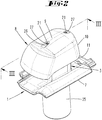
- the roof vent shown in the drawings can be used as roofing plate in a roof skin.
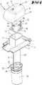
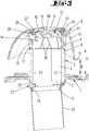
- the roofing plate 1 has an opening that can be made by water jet cutting. Within the opening extends a vent pipe 3, which forms a roof outside opening 4 and a roof inside opening 5.
- the roof outer side opening 4 is surrounded by the edge 6 of the ventilation tube 3 and has a distance A from the roofing plate 1.
- the roofing plate 1 and the ventilation pipe 3 are just like a cap 8 made of clay, concrete or other non-plastic material. But the vent tube 3 may also be connected to the roof covering plate 1 of the same material.
- the cap 8 has a roof portion 9 and a roof portion 9 surrounding wall portion 10 with a roof covering plate 1 projecting edge 11 whose distance B from the roofing plate 1 is less than the distance A of the end edge 6 of the vent pipe 3 of the roofing plate 1.
- the cap 8 has the shape of a bowl, which points in the use of the cap 8 with its bottom up and with its edge down.
- the ventilation pipe 3 is glued into the opening of the roofing plate 1 such that the lower end edge 7 protrudes slightly below the underside of the roofing plate 1. On this edge 7 sits a collar of an adapter 22.
- the adapter 22 forms with its collar a support frame 23, which is supported on the edge 7 of the ventilation tube 3.
- the adapter 22 also forms a connection flange 24, which engages in an opening of a roof inside the fall or vent pipe 25.
- There are at least two, but optionally also three or four fastening elements 21 are provided, which are formed in the embodiment of tie rods. In the embodiment, there are threaded rods 21 which carry an external thread over its entire length, but at least in its end portions.
- the downwardly facing end of the fastener 21 carries a radial projection, which may be formed by a screwed onto the end of the fastener 21 nut.
- the end of the fastener 21 is inserted in an opening of the adapter 22, so that upward tensile forces can be applied to the adapter 22.
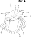
- a support frame 13 of a cap carrier 12 On the outside of the roof facing edge 6 of the vent tube 3 sits a support frame 13 of a cap carrier 12.
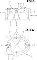
- the support frame 13 is formed by a lower portion of the cap carrier 12. From the support frame 13 protrude opposite support webs 15,17.
- the two support webs 15,17 of the cap carrier 12 are connected to each other with a Strömungsleitwand having openings through which the fasteners 21 protrude.
- nuts 28 which are screwed onto the fastening elements 21, the cap carrier 12 is braced against the edge 6 of the ventilation tube 3.
- the relevant clamping force is introduced via the adapter 22 in the opposite edge 7.
- V-shaped support webs 16 are provided, which, like the support webs 15,17 carry an air guide 19 of the upper portion 18 of the cap carrier 12.
- the air guide 19 is curved towards a vertex 20.
- the apex 20 is formed by a projection which projects from the upper portion 18 in the direction of the ventilation pipe 3.
- the area between the air guide surface 19 of the upper portion 18 of the cap carrier 12 and the lower portion 13 of the cap carrier 12 forms a central portion 14 which forms a flow zone through which air can escape from the ventilation channel 2.
- the support webs 15,16,17 are arranged so that their narrow sides are in the flow direction, so that the support webs 15,16,17 provide the lowest flow resistance.
- the portion 18 of the cap carrier 12, which forms the air guide 19, has an approximately oval floor plan.
- the section 18 forms the free-form surface designed as an air guide surface 19.
- the air guide 19 Approximately to the center of the ventilation tube 18, the air guide 19 has a downwardly directed projection. In the radial outer direction, a convexly curved surface connects to the vertex 20 of the projection, which merges to the edge of the air guide 19 in a horizontal direction.
- the roof portion 9 of the made of clay or other suitable non-plastic cap 8 On the upper portion 18 of the cap carrier made of plastic 12 is the roof portion 9 of the made of clay or other suitable non-plastic cap 8.
- the roof portion 9 of the cap 8 has openings 26 through which the end portions of the fasteners 21 protrude.
- the end portions of the fasteners 21 each have an external thread, so that the cap 8 can be attached by means of two screwed onto the external thread nuts 27 on the fan. By loosening the nuts 27, the cap 8 can be removed for maintenance purposes. Then the cap carrier 12 can be cleaned or replaced if necessary. To replace the cap carrier 12, the nuts 28 are to be solved.
- the clay cap does not have to be glued to the tube made of clay. It can be used a plastic intermediate part in the form of the cap carrier 12, which has a maximum ventilation cross-section in the region of the ventilation zone 14.
- the substructure made of plastic is connected via form-locking means with the roofing plate 1. It is preferably a detachable anchoring.
- the positive connection is preferably made via the threaded rods 21. This makes it possible to secure the cap 8 via a screw on the roofing plate 1. A disassembly of the cap 8 for inspection purposes is possible.
- adapter 22 and connecting tube 25 may also be in one piece. Again FIG. 7 can be seen, the adapter 22 forms a step on which the lower edge 7 of the ventilation tube 3 can be supported.
- the cap carrier 12 allows by its realization the realization of comparatively large flow cross-sections through the central portion 14.
- the cap carrier 12 is further formed streamlined. He has for this purpose the above-mentioned air guide 19. He is shaped in particular as a flow body, the low-leakage from the bottom emerging air flow distracts to the side. This will be with the in the FIG. 5 illustrated arrows clarifies. This leads to a reduction in energy consumption and noise in the ventilation system. All visible parts of the roof ventilator according to the invention are made of clay.
- the cap carrier 12 is preferably a pure internal construction, which, since it is not visible, also does not have to be adapted to the color parts in terms of color.
- the roof vent can be connected to kitchen hoods or other home ventilation systems.
- the outer visible parts can not only be made of a ceramic material, such as clay.
- the outer visible parts can also be made of other materials, such as concrete, fiber cement or cast concrete.
- Roof ventilator which is characterized in that the fastening element 21 an opening 26 of a roof portion 9 of the cap 8 and the vent pipe 3 by cross-attaching the cap carrier 12 on the vent pipe 3.
- Roof ventilator which is characterized in that the flow-through zone 14 extends between support webs 15,16,17 of the cap carrier 12, wherein the support webs 15,16,17 with its underside on a supported on its end edge of the vent tube 3 support frame 13 and with her upper end with an upper portion 18 of the cap carrier 12 are attached.
- Roof ventilator which is characterized in that the material is clay, concrete or a mineral fiber composite material.
- Roof ventilator which is characterized in that the fastening elements 21 can be biased against the edge 7 of the roof inside opening of the ventilation tube 3.
- Roof ventilator which is characterized by a at the edge of the roof inside opening of the ventilation duct 2 supporting adapter 22 for connecting a vent pipe or downpipe 25th
- Roof ventilator which is characterized in that the fastening elements 21 are attached to a roof on the inside edge 7 of the adapter 22.
- Roof ventilator which is characterized in that the fastening elements 21 are tie rods, which in particular have an external thread on which a nut 27 is screwed.
- Roof ventilator characterized in that the upper portion 18 of the cap carrier 12 forms an air guide 19, above which the roof portion 9 of the cap 8 extends.
- Roof ventilator which is characterized in that the distance B of the edge 11 of a wall portion 10 of the cap 8 to the roofing plate 1 is less than the distance A of the roof outside edge 6 of the ventilation tube 3 to the roofing plate.
- Roof ventilator which is characterized in that the ventilation pipe 3 is glued into an opening of the roofing plate 1 or materially connected to the roofing plate 1.
Landscapes
- Engineering & Computer Science (AREA)
- Architecture (AREA)
- Civil Engineering (AREA)
- Structural Engineering (AREA)
- Chemical & Material Sciences (AREA)
- Combustion & Propulsion (AREA)
- Mechanical Engineering (AREA)
- General Engineering & Computer Science (AREA)
- Roof Covering Using Slabs Or Stiff Sheets (AREA)
Priority Applications (1)
| Application Number | Priority Date | Filing Date | Title |
|---|---|---|---|
| PL14171086T PL2818802T3 (pl) | 2013-06-25 | 2014-06-04 | Urządzenie wentylujące dach z materiału mineralnego, zwłaszcza ceramiki |
Applications Claiming Priority (1)
| Application Number | Priority Date | Filing Date | Title |
|---|---|---|---|
| DE102013106605.4A DE102013106605A1 (de) | 2013-06-25 | 2013-06-25 | Dachentlüftungsvorrichtung aus einem mineralischen Werkstoff, insbesondere Ton |
Publications (2)
| Publication Number | Publication Date |
|---|---|
| EP2818802A1 EP2818802A1 (de) | 2014-12-31 |
| EP2818802B1 true EP2818802B1 (de) | 2017-08-30 |
Family
ID=50884740
Family Applications (1)
| Application Number | Title | Priority Date | Filing Date |
|---|---|---|---|
| EP14171086.3A Active EP2818802B1 (de) | 2013-06-25 | 2014-06-04 | Dachentlüftungsvorrichtung aus einem mineralischen Werkstoff, insbesondere Ton |
Country Status (3)
| Country | Link |
|---|---|
| EP (1) | EP2818802B1 (pl) |
| DE (1) | DE102013106605A1 (pl) |
| PL (1) | PL2818802T3 (pl) |
Cited By (1)
| Publication number | Priority date | Publication date | Assignee | Title |
|---|---|---|---|---|
| EP4624814A1 (en) * | 2024-03-29 | 2025-10-01 | Quick Slide B.V. | Flat roof duct connector system with fixedly mountable baseplate member and sealingly clampable roofing material disc around a water barrier wall |
Families Citing this family (2)
| Publication number | Priority date | Publication date | Assignee | Title |
|---|---|---|---|---|
| CN113062352B (zh) * | 2021-03-09 | 2023-08-25 | 应急管理部国家自然灾害防治研究院 | 一种可提升城市道路美观的地下管廊通风透光结构 |
| FR3167965A1 (fr) * | 2024-10-28 | 2026-05-01 | Nicolas Clément DUCROT Jean | Systeme de raccordement entre un reseau aeraulique et une tuile a douille d’un batiment, et ensemble de traversée de toit afferent |
Family Cites Families (14)
| Publication number | Priority date | Publication date | Assignee | Title |
|---|---|---|---|---|
| DE2155015A1 (de) | 1971-11-05 | 1973-05-10 | Marin Schnorr | Ueberdach-entlueftungsvorrichtung |
| US4399743A (en) * | 1981-10-15 | 1983-08-23 | Plastic Oddities, Inc. | Vent pipe cap |
| DE8710070U1 (de) | 1987-07-23 | 1987-10-22 | Schnorr, Marin, 6729 Hatzenbühl | Überdach-Entlüftungsvorrichtung |
| DE9313128U1 (de) * | 1993-09-01 | 1995-01-05 | Klöber, Johannes, 58256 Ennepetal | Dachdurchführung |
| DE4329618A1 (de) | 1993-09-02 | 1995-03-09 | Kloeber Johannes | Dachentlüfter |
| DE19605462C2 (de) | 1996-02-14 | 1999-12-09 | Max Gerhaher | Dunstrohr zur Dachdurchführung |
| DE29602618U1 (de) * | 1996-02-14 | 1996-03-28 | Gerhaher, Franz, Dr., 94315 Straubing | Dunstrohr zur Dachdurchführung |
| DE19628251C1 (de) * | 1996-07-12 | 1997-11-20 | Thomas Purr | Überdach-Entlüftungsvorrichtung |
| DE29714689U1 (de) | 1997-08-16 | 1997-10-09 | Walther Dachziegel GmbH, 90579 Langenzenn | Überdachentlüfter |
| DE19806712C1 (de) * | 1998-02-18 | 1999-10-07 | Nelskamp Dachziegelwerke Gmbh | Vorrichtung zur Führung eines Entlüftungskanals über Dach |
| DE20006070U1 (de) | 2000-04-01 | 2000-08-17 | Schnorr, Marin, 76770 Hatzenbühl | Vorrichtung zum Verbinden einer Gebäude-Abwasserverrohrung mit einem Überdach-Entlüfter |
| DE20017106U1 (de) * | 2000-10-04 | 2000-12-21 | Heuel & Soehne Gmbh J | Dachlüfter |
| DE20305043U1 (de) * | 2003-03-28 | 2003-06-05 | Heller, Jürgen Karl-Heinz, 26316 Varel | Lüftungsziegel |
| US6954947B1 (en) * | 2004-04-27 | 2005-10-18 | Williams Jr Marvin J | Pluming vent cover |
-
2013
- 2013-06-25 DE DE102013106605.4A patent/DE102013106605A1/de not_active Ceased
-
2014
- 2014-06-04 EP EP14171086.3A patent/EP2818802B1/de active Active
- 2014-06-04 PL PL14171086T patent/PL2818802T3/pl unknown
Non-Patent Citations (1)
| Title |
|---|
| None * |
Cited By (2)
| Publication number | Priority date | Publication date | Assignee | Title |
|---|---|---|---|---|
| EP4624814A1 (en) * | 2024-03-29 | 2025-10-01 | Quick Slide B.V. | Flat roof duct connector system with fixedly mountable baseplate member and sealingly clampable roofing material disc around a water barrier wall |
| NL2037371B1 (en) * | 2024-03-29 | 2025-10-10 | Quick Slide B V | Flat roof duct connector system with fixedly mountable baseplate member and sealingly clampable roofing material disc around a water barrier wall. |
Also Published As
| Publication number | Publication date |
|---|---|
| EP2818802A1 (de) | 2014-12-31 |
| PL2818802T3 (pl) | 2018-01-31 |
| DE102013106605A1 (de) | 2015-01-08 |
Similar Documents
| Publication | Publication Date | Title |
|---|---|---|
| EP2550410B1 (de) | Strahlregler | |
| DE19909049A1 (de) | Einfassung zur Montage in einem Steildach, Verfahren zum Installieren einer rechteckigen Einfassungseinheit und Dachkonstruktion | |
| DE202009007490U1 (de) | Vorrichtung zur Befestigung eines Moduls zur Nutzung von Sonnenenergie | |
| DE202009004938U1 (de) | Montagebausatz | |
| EP2818802A1 (de) | Dachentlüftungsvorrichtung aus einem mineralischen Werkstoff, insbesondere Ton | |
| EP2186964B1 (de) | Dacheindeckung mit mindestens zwei Metallblechen zwischen Profilen und Solaranlage auf dieser Dacheindeckung | |
| EP1813737B1 (de) | Dachdurchgang und Verfahren zu seiner Herstellung | |
| DE102009053652B4 (de) | Dach-Durchführung für eine Rohrleitung | |
| EP3659685A1 (de) | Sandkastensystem | |
| EP2030695B1 (de) | Handbrause | |
| EP2246622A2 (de) | Entlüftungsanordnung zur Montage auf einem Gebäudedach | |
| EP1853770B1 (de) | Sanitäre wasserauslaufarmatur mit strahlrichtungsgeber zum ablenken des austretenden wasserstrahls | |
| DE9417927U1 (de) | Befestigungselement für Dämm- und Dichtungsmaterial auf Flachdächern | |
| EP1331315B1 (de) | Ablaufvorrichtung für einen Fliesenfussboden | |
| DE19532851C1 (de) | Neigungsverstellbare Dachdurchführung | |
| EP2394004B1 (de) | Durchführung von rohrartigen elementen durch flächige gebäudekonstruktionen | |
| EP2395178A2 (de) | Fassadensystem mit Reparaturhalter | |
| DE19815493C2 (de) | Schornsteinkopf | |
| DE60004765T2 (de) | Schutzvorrichtung | |
| DE20307303U1 (de) | Lüftungsziegel | |
| DE102010018362B4 (de) | Filtereinheit und damit ausgerüsteter Filter | |
| DE202016000041U1 (de) | Tragkonstruktion für Vordach und Überdachung | |
| DE202006020969U1 (de) | Flachdach-Lüfter | |
| AT6563U1 (de) | Zelt | |
| DE10319007B4 (de) | Anschlußarmatur für die Luftzu- und/oder -abführung eines Raumlüftungsgerätes |
Legal Events
| Date | Code | Title | Description |
|---|---|---|---|
| PUAI | Public reference made under article 153(3) epc to a published international application that has entered the european phase |
Free format text: ORIGINAL CODE: 0009012 |
|
| 17P | Request for examination filed |
Effective date: 20140604 |
|
| AK | Designated contracting states |
Kind code of ref document: A1 Designated state(s): AL AT BE BG CH CY CZ DE DK EE ES FI FR GB GR HR HU IE IS IT LI LT LU LV MC MK MT NL NO PL PT RO RS SE SI SK SM TR |
|
| AX | Request for extension of the european patent |
Extension state: BA ME |
|
| R17P | Request for examination filed (corrected) |
Effective date: 20150218 |
|
| RBV | Designated contracting states (corrected) |
Designated state(s): AL AT BE BG CH CY CZ DE DK EE ES FI FR GB GR HR HU IE IS IT LI LT LU LV MC MK MT NL NO PL PT RO RS SE SI SK SM TR |
|
| 17Q | First examination report despatched |
Effective date: 20160610 |
|
| GRAP | Despatch of communication of intention to grant a patent |
Free format text: ORIGINAL CODE: EPIDOSNIGR1 |
|
| INTG | Intention to grant announced |
Effective date: 20161118 |
|
| GRAJ | Information related to disapproval of communication of intention to grant by the applicant or resumption of examination proceedings by the epo deleted |
Free format text: ORIGINAL CODE: EPIDOSDIGR1 |
|
| GRAP | Despatch of communication of intention to grant a patent |
Free format text: ORIGINAL CODE: EPIDOSNIGR1 |
|
| INTC | Intention to grant announced (deleted) | ||
| INTG | Intention to grant announced |
Effective date: 20170228 |
|
| GRAS | Grant fee paid |
Free format text: ORIGINAL CODE: EPIDOSNIGR3 |
|
| GRAJ | Information related to disapproval of communication of intention to grant by the applicant or resumption of examination proceedings by the epo deleted |
Free format text: ORIGINAL CODE: EPIDOSDIGR1 |
|
| GRAL | Information related to payment of fee for publishing/printing deleted |
Free format text: ORIGINAL CODE: EPIDOSDIGR3 |
|
| GRAR | Information related to intention to grant a patent recorded |
Free format text: ORIGINAL CODE: EPIDOSNIGR71 |
|
| GRAA | (expected) grant |
Free format text: ORIGINAL CODE: 0009210 |
|
| INTC | Intention to grant announced (deleted) | ||
| AK | Designated contracting states |
Kind code of ref document: B1 Designated state(s): AL AT BE BG CH CY CZ DE DK EE ES FI FR GB GR HR HU IE IS IT LI LT LU LV MC MK MT NL NO PL PT RO RS SE SI SK SM TR |
|
| INTG | Intention to grant announced |
Effective date: 20170724 |
|
| REG | Reference to a national code |
Ref country code: GB Ref legal event code: FG4D Free format text: NOT ENGLISH |
|
| REG | Reference to a national code |
Ref country code: CH Ref legal event code: EP |
|
| REG | Reference to a national code |
Ref country code: AT Ref legal event code: REF Ref document number: 923929 Country of ref document: AT Kind code of ref document: T Effective date: 20170915 |
|
| REG | Reference to a national code |
Ref country code: IE Ref legal event code: FG4D Free format text: LANGUAGE OF EP DOCUMENT: GERMAN |
|
| REG | Reference to a national code |
Ref country code: DE Ref legal event code: R096 Ref document number: 502014005215 Country of ref document: DE |
|
| REG | Reference to a national code |
Ref country code: NL Ref legal event code: MP Effective date: 20170830 |
|
| REG | Reference to a national code |
Ref country code: LT Ref legal event code: MG4D |
|
| PG25 | Lapsed in a contracting state [announced via postgrant information from national office to epo] |
Ref country code: NO Free format text: LAPSE BECAUSE OF FAILURE TO SUBMIT A TRANSLATION OF THE DESCRIPTION OR TO PAY THE FEE WITHIN THE PRESCRIBED TIME-LIMIT Effective date: 20171130 Ref country code: HR Free format text: LAPSE BECAUSE OF FAILURE TO SUBMIT A TRANSLATION OF THE DESCRIPTION OR TO PAY THE FEE WITHIN THE PRESCRIBED TIME-LIMIT Effective date: 20170830 Ref country code: SE Free format text: LAPSE BECAUSE OF FAILURE TO SUBMIT A TRANSLATION OF THE DESCRIPTION OR TO PAY THE FEE WITHIN THE PRESCRIBED TIME-LIMIT Effective date: 20170830 Ref country code: FI Free format text: LAPSE BECAUSE OF FAILURE TO SUBMIT A TRANSLATION OF THE DESCRIPTION OR TO PAY THE FEE WITHIN THE PRESCRIBED TIME-LIMIT Effective date: 20170830 Ref country code: LT Free format text: LAPSE BECAUSE OF FAILURE TO SUBMIT A TRANSLATION OF THE DESCRIPTION OR TO PAY THE FEE WITHIN THE PRESCRIBED TIME-LIMIT Effective date: 20170830 |
|
| PG25 | Lapsed in a contracting state [announced via postgrant information from national office to epo] |
Ref country code: IS Free format text: LAPSE BECAUSE OF FAILURE TO SUBMIT A TRANSLATION OF THE DESCRIPTION OR TO PAY THE FEE WITHIN THE PRESCRIBED TIME-LIMIT Effective date: 20171230 Ref country code: RS Free format text: LAPSE BECAUSE OF FAILURE TO SUBMIT A TRANSLATION OF THE DESCRIPTION OR TO PAY THE FEE WITHIN THE PRESCRIBED TIME-LIMIT Effective date: 20170830 Ref country code: GR Free format text: LAPSE BECAUSE OF FAILURE TO SUBMIT A TRANSLATION OF THE DESCRIPTION OR TO PAY THE FEE WITHIN THE PRESCRIBED TIME-LIMIT Effective date: 20171201 Ref country code: LV Free format text: LAPSE BECAUSE OF FAILURE TO SUBMIT A TRANSLATION OF THE DESCRIPTION OR TO PAY THE FEE WITHIN THE PRESCRIBED TIME-LIMIT Effective date: 20170830 Ref country code: BG Free format text: LAPSE BECAUSE OF FAILURE TO SUBMIT A TRANSLATION OF THE DESCRIPTION OR TO PAY THE FEE WITHIN THE PRESCRIBED TIME-LIMIT Effective date: 20171130 Ref country code: ES Free format text: LAPSE BECAUSE OF FAILURE TO SUBMIT A TRANSLATION OF THE DESCRIPTION OR TO PAY THE FEE WITHIN THE PRESCRIBED TIME-LIMIT Effective date: 20170830 |
|
| PG25 | Lapsed in a contracting state [announced via postgrant information from national office to epo] |
Ref country code: NL Free format text: LAPSE BECAUSE OF FAILURE TO SUBMIT A TRANSLATION OF THE DESCRIPTION OR TO PAY THE FEE WITHIN THE PRESCRIBED TIME-LIMIT Effective date: 20170830 |
|
| PG25 | Lapsed in a contracting state [announced via postgrant information from national office to epo] |
Ref country code: RO Free format text: LAPSE BECAUSE OF FAILURE TO SUBMIT A TRANSLATION OF THE DESCRIPTION OR TO PAY THE FEE WITHIN THE PRESCRIBED TIME-LIMIT Effective date: 20170830 Ref country code: DK Free format text: LAPSE BECAUSE OF FAILURE TO SUBMIT A TRANSLATION OF THE DESCRIPTION OR TO PAY THE FEE WITHIN THE PRESCRIBED TIME-LIMIT Effective date: 20170830 |
|
| PG25 | Lapsed in a contracting state [announced via postgrant information from national office to epo] |
Ref country code: IT Free format text: LAPSE BECAUSE OF FAILURE TO SUBMIT A TRANSLATION OF THE DESCRIPTION OR TO PAY THE FEE WITHIN THE PRESCRIBED TIME-LIMIT Effective date: 20170830 Ref country code: SK Free format text: LAPSE BECAUSE OF FAILURE TO SUBMIT A TRANSLATION OF THE DESCRIPTION OR TO PAY THE FEE WITHIN THE PRESCRIBED TIME-LIMIT Effective date: 20170830 Ref country code: SM Free format text: LAPSE BECAUSE OF FAILURE TO SUBMIT A TRANSLATION OF THE DESCRIPTION OR TO PAY THE FEE WITHIN THE PRESCRIBED TIME-LIMIT Effective date: 20170830 Ref country code: EE Free format text: LAPSE BECAUSE OF FAILURE TO SUBMIT A TRANSLATION OF THE DESCRIPTION OR TO PAY THE FEE WITHIN THE PRESCRIBED TIME-LIMIT Effective date: 20170830 |
|
| REG | Reference to a national code |
Ref country code: DE Ref legal event code: R097 Ref document number: 502014005215 Country of ref document: DE |
|
| REG | Reference to a national code |
Ref country code: FR Ref legal event code: PLFP Year of fee payment: 5 |
|
| PLBE | No opposition filed within time limit |
Free format text: ORIGINAL CODE: 0009261 |
|
| STAA | Information on the status of an ep patent application or granted ep patent |
Free format text: STATUS: NO OPPOSITION FILED WITHIN TIME LIMIT |
|
| 26N | No opposition filed |
Effective date: 20180531 |
|
| PG25 | Lapsed in a contracting state [announced via postgrant information from national office to epo] |
Ref country code: SI Free format text: LAPSE BECAUSE OF FAILURE TO SUBMIT A TRANSLATION OF THE DESCRIPTION OR TO PAY THE FEE WITHIN THE PRESCRIBED TIME-LIMIT Effective date: 20170830 |
|
| PG25 | Lapsed in a contracting state [announced via postgrant information from national office to epo] |
Ref country code: MT Free format text: LAPSE BECAUSE OF FAILURE TO SUBMIT A TRANSLATION OF THE DESCRIPTION OR TO PAY THE FEE WITHIN THE PRESCRIBED TIME-LIMIT Effective date: 20170830 |
|
| REG | Reference to a national code |
Ref country code: CH Ref legal event code: PL |
|
| GBPC | Gb: european patent ceased through non-payment of renewal fee |
Effective date: 20180604 |
|
| REG | Reference to a national code |
Ref country code: BE Ref legal event code: MM Effective date: 20180630 |
|
| REG | Reference to a national code |
Ref country code: IE Ref legal event code: MM4A |
|
| PG25 | Lapsed in a contracting state [announced via postgrant information from national office to epo] |
Ref country code: MC Free format text: LAPSE BECAUSE OF FAILURE TO SUBMIT A TRANSLATION OF THE DESCRIPTION OR TO PAY THE FEE WITHIN THE PRESCRIBED TIME-LIMIT Effective date: 20170830 Ref country code: LU Free format text: LAPSE BECAUSE OF NON-PAYMENT OF DUE FEES Effective date: 20180604 |
|
| PG25 | Lapsed in a contracting state [announced via postgrant information from national office to epo] |
Ref country code: IE Free format text: LAPSE BECAUSE OF NON-PAYMENT OF DUE FEES Effective date: 20180604 Ref country code: GB Free format text: LAPSE BECAUSE OF NON-PAYMENT OF DUE FEES Effective date: 20180604 Ref country code: LI Free format text: LAPSE BECAUSE OF NON-PAYMENT OF DUE FEES Effective date: 20180630 Ref country code: CH Free format text: LAPSE BECAUSE OF NON-PAYMENT OF DUE FEES Effective date: 20180630 |
|
| PG25 | Lapsed in a contracting state [announced via postgrant information from national office to epo] |
Ref country code: BE Free format text: LAPSE BECAUSE OF NON-PAYMENT OF DUE FEES Effective date: 20180630 |
|
| PG25 | Lapsed in a contracting state [announced via postgrant information from national office to epo] |
Ref country code: TR Free format text: LAPSE BECAUSE OF FAILURE TO SUBMIT A TRANSLATION OF THE DESCRIPTION OR TO PAY THE FEE WITHIN THE PRESCRIBED TIME-LIMIT Effective date: 20170830 |
|
| PG25 | Lapsed in a contracting state [announced via postgrant information from national office to epo] |
Ref country code: PT Free format text: LAPSE BECAUSE OF FAILURE TO SUBMIT A TRANSLATION OF THE DESCRIPTION OR TO PAY THE FEE WITHIN THE PRESCRIBED TIME-LIMIT Effective date: 20170830 Ref country code: HU Free format text: LAPSE BECAUSE OF FAILURE TO SUBMIT A TRANSLATION OF THE DESCRIPTION OR TO PAY THE FEE WITHIN THE PRESCRIBED TIME-LIMIT; INVALID AB INITIO Effective date: 20140604 |
|
| PG25 | Lapsed in a contracting state [announced via postgrant information from national office to epo] |
Ref country code: MK Free format text: LAPSE BECAUSE OF NON-PAYMENT OF DUE FEES Effective date: 20170830 Ref country code: CY Free format text: LAPSE BECAUSE OF FAILURE TO SUBMIT A TRANSLATION OF THE DESCRIPTION OR TO PAY THE FEE WITHIN THE PRESCRIBED TIME-LIMIT Effective date: 20170830 |
|
| PG25 | Lapsed in a contracting state [announced via postgrant information from national office to epo] |
Ref country code: AL Free format text: LAPSE BECAUSE OF FAILURE TO SUBMIT A TRANSLATION OF THE DESCRIPTION OR TO PAY THE FEE WITHIN THE PRESCRIBED TIME-LIMIT Effective date: 20170830 |
|
| P01 | Opt-out of the competence of the unified patent court (upc) registered |
Effective date: 20230512 |
|
| PGFP | Annual fee paid to national office [announced via postgrant information from national office to epo] |
Ref country code: PL Payment date: 20260528 Year of fee payment: 13 |
|
| PGFP | Annual fee paid to national office [announced via postgrant information from national office to epo] |
Ref country code: DE Payment date: 20260623 Year of fee payment: 13 |
|
| PGFP | Annual fee paid to national office [announced via postgrant information from national office to epo] |
Ref country code: AT Payment date: 20260618 Year of fee payment: 13 |
|
| PGFP | Annual fee paid to national office [announced via postgrant information from national office to epo] |
Ref country code: CZ Payment date: 20260522 Year of fee payment: 13 |
|
| PGFP | Annual fee paid to national office [announced via postgrant information from national office to epo] |
Ref country code: FR Payment date: 20260622 Year of fee payment: 13 |