EP2818903A2 - Connecteur de transition de câble à fibre optique hybride - Google Patents
Connecteur de transition de câble à fibre optique hybride Download PDFInfo
- Publication number
- EP2818903A2 EP2818903A2 EP20140173563 EP14173563A EP2818903A2 EP 2818903 A2 EP2818903 A2 EP 2818903A2 EP 20140173563 EP20140173563 EP 20140173563 EP 14173563 A EP14173563 A EP 14173563A EP 2818903 A2 EP2818903 A2 EP 2818903A2
- Authority
- EP
- European Patent Office
- Prior art keywords
- connector
- cable
- slot
- fiber optic
- connector assembly
- Prior art date
- Legal status (The legal status is an assumption and is not a legal conclusion. Google has not performed a legal analysis and makes no representation as to the accuracy of the status listed.)
- Withdrawn
Links
- 239000000835 fiber Substances 0.000 title claims abstract description 45
- 230000007704 transition Effects 0.000 title description 4
- 239000013307 optical fiber Substances 0.000 claims abstract description 28
- 239000000758 substrate Substances 0.000 claims abstract description 25
- 239000004020 conductor Substances 0.000 claims description 49
- 230000013011 mating Effects 0.000 claims description 8
- 230000001419 dependent effect Effects 0.000 claims description 2
- 239000000463 material Substances 0.000 description 3
- RYGMFSIKBFXOCR-UHFFFAOYSA-N Copper Chemical compound [Cu] RYGMFSIKBFXOCR-UHFFFAOYSA-N 0.000 description 2
- XAGFODPZIPBFFR-UHFFFAOYSA-N aluminium Chemical compound [Al] XAGFODPZIPBFFR-UHFFFAOYSA-N 0.000 description 2
- 229910052782 aluminium Inorganic materials 0.000 description 2
- 230000008901 benefit Effects 0.000 description 2
- 229910052802 copper Inorganic materials 0.000 description 2
- 239000010949 copper Substances 0.000 description 2
- 238000012986 modification Methods 0.000 description 2
- 230000004048 modification Effects 0.000 description 2
- 239000004800 polyvinyl chloride Substances 0.000 description 2
- ATJFFYVFTNAWJD-UHFFFAOYSA-N Tin Chemical compound [Sn] ATJFFYVFTNAWJD-UHFFFAOYSA-N 0.000 description 1
- 230000005540 biological transmission Effects 0.000 description 1
- 238000004140 cleaning Methods 0.000 description 1
- 238000010276 construction Methods 0.000 description 1
- 238000011161 development Methods 0.000 description 1
- 230000018109 developmental process Effects 0.000 description 1
- 238000005516 engineering process Methods 0.000 description 1
- 238000000034 method Methods 0.000 description 1
- 229920000915 polyvinyl chloride Polymers 0.000 description 1
- 125000006850 spacer group Chemical group 0.000 description 1
Images

Classifications
-
- G—PHYSICS
- G02—OPTICS
- G02B—OPTICAL ELEMENTS, SYSTEMS OR APPARATUS
- G02B6/00—Light guides; Structural details of arrangements comprising light guides and other optical elements, e.g. couplings
- G02B6/24—Coupling light guides
- G02B6/36—Mechanical coupling means
- G02B6/38—Mechanical coupling means having fibre to fibre mating means
- G02B6/3807—Dismountable connectors, i.e. comprising plugs
- G02B6/381—Dismountable connectors, i.e. comprising plugs of the ferrule type, e.g. fibre ends embedded in ferrules, connecting a pair of fibres
- G02B6/3817—Dismountable connectors, i.e. comprising plugs of the ferrule type, e.g. fibre ends embedded in ferrules, connecting a pair of fibres containing optical and electrical conductors
-
- G—PHYSICS
- G02—OPTICS
- G02B—OPTICAL ELEMENTS, SYSTEMS OR APPARATUS
- G02B6/00—Light guides; Structural details of arrangements comprising light guides and other optical elements, e.g. couplings
- G02B6/24—Coupling light guides
- G02B6/36—Mechanical coupling means
- G02B6/38—Mechanical coupling means having fibre to fibre mating means
- G02B6/3807—Dismountable connectors, i.e. comprising plugs
-
- G—PHYSICS
- G02—OPTICS
- G02B—OPTICAL ELEMENTS, SYSTEMS OR APPARATUS
- G02B6/00—Light guides; Structural details of arrangements comprising light guides and other optical elements, e.g. couplings
- G02B6/24—Coupling light guides
- G02B6/36—Mechanical coupling means
- G02B6/38—Mechanical coupling means having fibre to fibre mating means
- G02B6/3807—Dismountable connectors, i.e. comprising plugs
- G02B6/381—Dismountable connectors, i.e. comprising plugs of the ferrule type, e.g. fibre ends embedded in ferrules, connecting a pair of fibres
- G02B6/3825—Dismountable connectors, i.e. comprising plugs of the ferrule type, e.g. fibre ends embedded in ferrules, connecting a pair of fibres with an intermediate part, e.g. adapter, receptacle, linking two plugs
-
- G—PHYSICS
- G02—OPTICS
- G02B—OPTICAL ELEMENTS, SYSTEMS OR APPARATUS
- G02B6/00—Light guides; Structural details of arrangements comprising light guides and other optical elements, e.g. couplings
- G02B6/24—Coupling light guides
- G02B6/36—Mechanical coupling means
- G02B6/38—Mechanical coupling means having fibre to fibre mating means
- G02B6/3807—Dismountable connectors, i.e. comprising plugs
- G02B6/3869—Mounting ferrules to connector body, i.e. plugs
- G02B6/387—Connector plugs comprising two complementary members, e.g. shells, caps, covers, locked together
-
- G—PHYSICS
- G02—OPTICS
- G02B—OPTICAL ELEMENTS, SYSTEMS OR APPARATUS
- G02B6/00—Light guides; Structural details of arrangements comprising light guides and other optical elements, e.g. couplings
- G02B6/24—Coupling light guides
- G02B6/36—Mechanical coupling means
- G02B6/38—Mechanical coupling means having fibre to fibre mating means
- G02B6/3807—Dismountable connectors, i.e. comprising plugs
- G02B6/3873—Connectors using guide surfaces for aligning ferrule ends, e.g. tubes, sleeves, V-grooves, rods, pins, balls
- G02B6/3874—Connectors using guide surfaces for aligning ferrule ends, e.g. tubes, sleeves, V-grooves, rods, pins, balls using tubes, sleeves to align ferrules
- G02B6/3878—Connectors using guide surfaces for aligning ferrule ends, e.g. tubes, sleeves, V-grooves, rods, pins, balls using tubes, sleeves to align ferrules comprising a plurality of ferrules, branching and break-out means
- G02B6/3879—Linking of individual connector plugs to an overconnector, e.g. using clamps, clips, common housings comprising several individual connector plugs
-
- G—PHYSICS
- G02—OPTICS
- G02B—OPTICAL ELEMENTS, SYSTEMS OR APPARATUS
- G02B6/00—Light guides; Structural details of arrangements comprising light guides and other optical elements, e.g. couplings
- G02B6/24—Coupling light guides
- G02B6/36—Mechanical coupling means
- G02B6/38—Mechanical coupling means having fibre to fibre mating means
- G02B6/3807—Dismountable connectors, i.e. comprising plugs
- G02B6/3873—Connectors using guide surfaces for aligning ferrule ends, e.g. tubes, sleeves, V-grooves, rods, pins, balls
- G02B6/3885—Multicore or multichannel optical connectors, i.e. one single ferrule containing more than one fibre, e.g. ribbon type
-
- G—PHYSICS
- G02—OPTICS
- G02B—OPTICAL ELEMENTS, SYSTEMS OR APPARATUS
- G02B6/00—Light guides; Structural details of arrangements comprising light guides and other optical elements, e.g. couplings
- G02B6/44—Mechanical structures for providing tensile strength and external protection for fibres, e.g. optical transmission cables
- G02B6/4401—Optical cables
- G02B6/4415—Cables for special applications
- G02B6/4416—Heterogeneous cables
-
- H—ELECTRICITY
- H01—ELECTRIC ELEMENTS
- H01B—CABLES; CONDUCTORS; INSULATORS; SELECTION OF MATERIALS FOR THEIR CONDUCTIVE, INSULATING OR DIELECTRIC PROPERTIES
- H01B11/00—Communication cables or conductors
- H01B11/22—Cables including at least one electrical conductor together with optical fibres
-
- H—ELECTRICITY
- H01—ELECTRIC ELEMENTS
- H01R—ELECTRICALLY-CONDUCTIVE CONNECTIONS; STRUCTURAL ASSOCIATIONS OF A PLURALITY OF MUTUALLY-INSULATED ELECTRICAL CONNECTING ELEMENTS; COUPLING DEVICES; CURRENT COLLECTORS
- H01R11/00—Individual connecting elements providing two or more spaced connecting locations for conductive members which are, or may be, thereby interconnected, e.g. end pieces for wires or cables supported by the wire or cable and having means for facilitating electrical connection to some other wire, terminal, or conductive member, blocks of binding posts
- H01R11/03—Individual connecting elements providing two or more spaced connecting locations for conductive members which are, or may be, thereby interconnected, e.g. end pieces for wires or cables supported by the wire or cable and having means for facilitating electrical connection to some other wire, terminal, or conductive member, blocks of binding posts characterised by the relationship between the connecting locations
- H01R11/05—Individual connecting elements providing two or more spaced connecting locations for conductive members which are, or may be, thereby interconnected, e.g. end pieces for wires or cables supported by the wire or cable and having means for facilitating electrical connection to some other wire, terminal, or conductive member, blocks of binding posts characterised by the relationship between the connecting locations the connecting locations having different types of direct connections
-
- H—ELECTRICITY
- H01—ELECTRIC ELEMENTS
- H01R—ELECTRICALLY-CONDUCTIVE CONNECTIONS; STRUCTURAL ASSOCIATIONS OF A PLURALITY OF MUTUALLY-INSULATED ELECTRICAL CONNECTING ELEMENTS; COUPLING DEVICES; CURRENT COLLECTORS
- H01R4/00—Electrically-conductive connections between two or more conductive members in direct contact, i.e. touching one another; Means for effecting or maintaining such contact; Electrically-conductive connections having two or more spaced connecting locations for conductors and using contact members penetrating insulation
- H01R4/58—Electrically-conductive connections between two or more conductive members in direct contact, i.e. touching one another; Means for effecting or maintaining such contact; Electrically-conductive connections having two or more spaced connecting locations for conductors and using contact members penetrating insulation characterised by the form or material of the contacting members
-
- G—PHYSICS
- G02—OPTICS
- G02B—OPTICAL ELEMENTS, SYSTEMS OR APPARATUS
- G02B6/00—Light guides; Structural details of arrangements comprising light guides and other optical elements, e.g. couplings
- G02B6/44—Mechanical structures for providing tensile strength and external protection for fibres, e.g. optical transmission cables
- G02B6/4439—Auxiliary devices
- G02B6/4471—Terminating devices ; Cable clamps
-
- H—ELECTRICITY
- H01—ELECTRIC ELEMENTS
- H01R—ELECTRICALLY-CONDUCTIVE CONNECTIONS; STRUCTURAL ASSOCIATIONS OF A PLURALITY OF MUTUALLY-INSULATED ELECTRICAL CONNECTING ELEMENTS; COUPLING DEVICES; CURRENT COLLECTORS
- H01R33/00—Coupling devices specially adapted for supporting apparatus and having one part acting as a holder providing support and electrical connection via a counterpart which is structurally associated with the apparatus, e.g. lamp holders; Separate parts thereof
- H01R33/945—Holders with built-in electrical component
Definitions
- the present invention is directed generally to connectors and more specifically, but not exclusively, to fiber optic and power connectors.
- hybrid optical fiber cable is intended to mean a cable that includes both power conductors and one or more fiber optic cords or cables.
- An example of a hybrid cable is the HFF cable, available from CommScope, Inc. (Joliet, Illinois).
- a single hybrid trunk cable can be used to power multiple sectors, thereby eliminating multiple runs of RF cable.
- the trunk cable In order to use a single hybrid trunk cable, at some point the trunk cable must transition to hybrid jumper cables. Typically, these are distributed inside an enclosure that transitions the trunk power conductor gauge to the jumper power conductor gauge and connects the optical fibers in the trunk to the optical fibers in the jumper cables.
- transitions are achieved by making connections inside the enclosure, requiring it to be opened, cables to be fed/mated to the enclosure, and power and fiber connections to be made, all in the field (e.g., on the top of cell sites near a remote radio unit (RRU)).
- RRU remote radio unit
- inventions of the invention are directed to a connector assembly for interconnecting hybrid optical fiber cables.
- the connector assembly may comprise a connector module and a housing within which the connector module resides.
- the connector module may comprise a mounting substrate, a plurality of fiber optic adapters mounted on the mounting substrate, and a plurality of power ports mounted on the mounting substrate.
- inventions of the invention are directed to a cable-connector assembly.
- the cable-connector assembly may comprise a connector assembly, a hybrid optical fiber cable, and a plurality of hybrid optical fiber jumper cables.
- the connector assembly may comprise: (i) a connector module comprising: a mounting substrate, a plurality of fiber optic adapters mounted on the mounting substrate and a plurality of power ports mounted on the mounting substrate; and (ii) a housing within which the connector module resides.
- the hybrid optical fiber cable may be inserted into the housing and attached to the fiber optic adapters and the power ports, and the plurality of hybrid optical fiber jumper cables may be inserted into the housing and attached to the fiber optic adapters and the power ports.
- embodiments of the invention are directed to a connector for interconnecting a round cable with a flat cable, comprising: a body having opposed end faces, at least one slot extending between the end faces, the slot having a rectangular profile, and upper and lower recesses extending, respectively, upwardly and downwardly from the slot, the upper and lower recesses being generally semicylindrical and aligned with each other.
- the connector assembly 10 has the capability of interconnecting hybrid optical fiber cables (i.e., cables that include both optical fibers and conductors for power transmission), and in particular may be suitable for interconnecting extended length hybrid optical fiber cables to shorter length jumper cables, and/or for connecting a single hybrid optical fiber cable with multiple hybrid optical fiber cables.
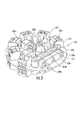
- the connector assembly 10 includes a connector module 12 and mating housings 14, 16 within which the connector module 12 resides. These components are described in greater detail below.
- the connector module 12 includes a base plate 20 on which eight separate LC adapters 22 are mounted.
- the LC adapters 22, which connect optical fibers, are of conventional construction and need not be described in detail herein. In some embodiments, other varieties of fiber optic couplers or adapters may be employed.
- PVC polyvinyl chloride
- the connector module 12 also includes a base plate 30 on which eight power ports 32 are mounted. Each of the power ports 32 includes two screw holes 34 that enable power conductors to be connected within the ports 32.
- the base plate 30 is typically formed of tin-plated copper and includes a central aperture 36. The base plate 30 is mounted in spaced relationship to the base plate 20 via four spacers 38.
- the housings 14 , 16 which in the illustrated embodiment take the shape of hollow truncated cones, are configured to hold the connector module 12 therein.
- the housing 14 includes a fitting that enables it to be attached to a hybrid fiber optic cable (not shown), which includes multiple optical fibers and power conductors.
- a hybrid optical fiber cable is the HELIAX® FiberFeed® Hybrid Cable, available from CommScope, Inc. (Joliet, Illinois).
- the housing 16 includes a fitting that receives four hybrid fiber optic jumper cables, or "direct tails" (not shown), wherein each jumper cable/direct tail corresponds to one "channel" of two power conductors and two optical fibers.
- An example of a jumper cable is the HELIAX® FiberFeed® Direct tail, also available from CommScope, Inc.
- the housings 14, 16 are typically formed of a polymeric material, such as PVC.
- the housings 14, 16 may be attached to each other by any manner of fastening methods; in the illustrated embodiment, they are attached via screws inserted into their rims 14a, 16a.
- the hybrid fiber optic cable would be terminated with the housing 14 at the factory, such that the optical fibers of the cable are threaded through the fitting of the housing 14 and inserted into the LC adapters 22, and the power conductors of the cable are threaded though the fitting of the housing 14 and inserted into the power ports 32.
- Hybrid fiber optic jumper cables would be inserted into each of the openings in the fitting of the housing 16, then inserted into the LC adapters 22 and the power ports 32.
- the optical fibers that are inserted through the housing 16 pass through the central aperture 36 of the base plate 30.
- the power conductors that are inserted through the housing 14 pass through the central aperture 24 of the base plate 20.
- the housings 14,16 can then be attached together via screws or the like.
- the connector assembly 10 can provide an enclosed connection point for hybrid fiber optic cables and jumper cables that is relatively compact and unobtrusive.
- the assembled housings 14, 16 have dimensions of between about 4 and 6 inches in diameter and 9 and 12 inches in length.
- Connector modules of differing configurations can also be used.
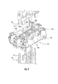
- a connector module 112 is shown mounted in a housing 114, with a mating housing 116 illustrated also.
- the connector module 112 includes only a single base plate 120 as a mounting substrate, on which six LC adapters 122 and six power ports 132 are mounted.
- the LC adapters 122 are mounted near the periphery of the base plate 120, and the power ports 132 are mounted radially inward from the LC adapters 122.
- the LC adapters 122 and power ports 132 are mounted such that they are staggered from each other, which provides space for a technician to insert and tighten a screw in each of the screw holes 134 of the power ports 132.
- the connector module 412 is similar to the connector module 112 in that it has only one base plate 420, and that it includes LC adapters 422 mounted near the periphery of the base plate 420. However, the connector module 412 also includes six power ports 440. Each power port 440 has the capacity to receive a "flat" power conductor in one side and up to three separate round conductors in the opposite side. A more detailed description of the power port 440 is set forth below.
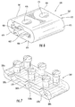
- the power port 440 comprises a body 462 (which can be unitary or formed of multiple pieces) having opposed top and bottom surfaces 464, 466, rounded sides 468, 470, and flat end faces 472, 474.
- a slot 478 extends between the end faces 472, 474.
- the slot 478 is generally rectangular in profile; the slot 478 typically has a height/width ratio of between about 0.25 and 0.5.
- Two generally semicylindrical recesses 480, 482 extend, respectively, upwardly and downwardly from a central portion of the slot 478 and are substantially aligned with each other on opposite edges of the slot 478.
- Two apertures 476 extend from the top surface 464 to the slot 478.
- the power port 440 can be used to interconnect a flat conductor with a round conductor.
- a flat cable 50 having a generally rectangular conductor 52 can enter the slot 478 of one of the power ports 440 at one end (in this instance, from above) and would occupy a portion of the volume of the slot 478 with the exception of the recesses 480, 482.
- a round cable 60 having a generally round conductor 62 can enter the slot 478 at the other end (in this instance, from below) and would fill portions of the recesses 480, 482, but not the remainder of the slot 478.
- the flat and round conductors 50, 60 abut each other within the body 462 of the power port 460. Screws 490 can be inserted into the apertures 476 to secure the conductors 50, 60 to the power ports 440.
- the power ports 440 may be formed of virtually any material, but in some embodiments are formed of a conductive material such as tin-coated aluminum.
- the conductors 50, 60 are formed of conductive materials; in one embodiment, the flat conductor 50 is formed of aluminum, and the round conductor 60 is formed of copper.
- the screws 490 may be configured to bias the conductors 50, 60 into contact with the power port 440 to improve the electrical connection.
- Such screws e.g., spring loaded screws
- a similar connector module 212 is shown in Figure 3 , which includes six LC adapters 222 and a power port 240 mounted on a base plate 220.
- the power port 240 (which is shown in Figure 7 ) is similar to the power port 440 with the exception that six generally semicylindrical recesses 280a-c, 282a-c are present in the slot 278. As a result, the power port 240 can be employed to interconnect up to three different round conductors with a single flat conductor.
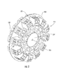
- the connector module 312 includes a single base plate 320, on which are mounted twelve LC adapters 322. Radially inwardly of the LC adapters 322, twelve power ports 332 are mounted on the base plate 320. However, the power ports 332 are configured to receive individual conductors on only one side ( i.e., the "rear" side of Figure 5 ); on the opposite side, a common contact plate 334 is mounted to the power ports 332 and is in electrical contact therewith.
- the common contact plate 334 which is formed of a conductive material, includes a central aperture 336 configured to receive a single conductor (not shown). This configuration enables power from multiple power conductors (in this instance, twelve) to be combined into a single conductor that exits the common contact plate 334.
Landscapes
- Physics & Mathematics (AREA)
- General Physics & Mathematics (AREA)
- Optics & Photonics (AREA)
- Connector Housings Or Holding Contact Members (AREA)
- Mechanical Coupling Of Light Guides (AREA)
Applications Claiming Priority (3)
| Application Number | Priority Date | Filing Date | Title |
|---|---|---|---|
| US201361838466P | 2013-06-24 | 2013-06-24 | |
| US201361838483P | 2013-06-24 | 2013-06-24 | |
| US14/293,434 US9606297B2 (en) | 2013-06-24 | 2014-06-02 | Transition connector for hybrid fiber optic cable |
Publications (2)
| Publication Number | Publication Date |
|---|---|
| EP2818903A2 true EP2818903A2 (fr) | 2014-12-31 |
| EP2818903A3 EP2818903A3 (fr) | 2015-05-27 |
Family
ID=50976552
Family Applications (1)
| Application Number | Title | Priority Date | Filing Date |
|---|---|---|---|
| EP14173563.9A Withdrawn EP2818903A3 (fr) | 2013-06-24 | 2014-06-23 | Connecteur de transition de câble à fibre optique hybride |
Country Status (4)
| Country | Link |
|---|---|
| US (1) | US9606297B2 (fr) |
| EP (1) | EP2818903A3 (fr) |
| CN (1) | CN104241938B (fr) |
| IN (1) | IN2014DE01680A (fr) |
Cited By (1)
| Publication number | Priority date | Publication date | Assignee | Title |
|---|---|---|---|---|
| WO2018053086A1 (fr) | 2016-09-15 | 2018-03-22 | Commscope Technologies Llc | Système de distribution d'énergie pour installations de radio-têtes à distance |
Families Citing this family (7)
| Publication number | Priority date | Publication date | Assignee | Title |
|---|---|---|---|---|
| MX2020001208A (es) * | 2017-07-31 | 2020-08-06 | Corning Optical Comm Rf Llc | Bifurcador con puertos de salida equidistantes. |
| WO2019027798A1 (fr) * | 2017-07-31 | 2019-02-07 | Corning Optical Communications Rf Llc | Diviseur avec ports commandés par impédance |
| WO2019027796A1 (fr) * | 2017-07-31 | 2019-02-07 | Corning Optical Communications Rf Llc | Diviseur avec ports en laiton intégrés |
| WO2019027794A1 (fr) * | 2017-07-31 | 2019-02-07 | Corning Optical Communications Rf Llc | Diviseur doté de ports commandés par impédance |
| CN110854635B (zh) * | 2018-07-24 | 2021-08-27 | 中国石油天然气股份有限公司 | 光电分离连接装置 |
| US11934015B2 (en) | 2020-06-09 | 2024-03-19 | Senko Advanced Components, Inc. | Multiport assembly and associated components |
| BR112023003664A2 (pt) * | 2020-08-31 | 2023-04-04 | Huawei Tech Co Ltd | Caixa de conexão de cabo óptico e adaptador |
Family Cites Families (21)
| Publication number | Priority date | Publication date | Assignee | Title |
|---|---|---|---|---|
| US4319799A (en) * | 1980-04-11 | 1982-03-16 | General Motors Corporation | Electrical connector with group terminal lock |
| DE3912139C2 (de) | 1989-04-13 | 1995-05-04 | Kabelmetal Electro Gmbh | Verfahren zum Umspritzen der Verbindungsstelle zweier elektrischer Leitungen |
| US4922058A (en) | 1989-04-20 | 1990-05-01 | Thomas & Betts Corporation | Connector for electrical conductors having similar or different cross-sectional shapes |
| CN1417607A (zh) * | 2002-11-22 | 2003-05-14 | 天津大学 | 光电混合光纤旋转连接器 |
| DE102005019318A1 (de) * | 2004-05-06 | 2005-11-24 | Brose Fahrzeugteile Gmbh & Co. Kommanditgesellschaft, Coburg | Verkabelungssystem einer Kraftfahrzeugtür |
| US7213975B2 (en) * | 2004-09-10 | 2007-05-08 | Adc Telecommunications, Inc. | Hybrid fiber/copper connector system and method |
| US7066716B2 (en) | 2004-09-15 | 2006-06-27 | General Electric Company | Cooling system for the trailing edges of turbine bucket airfoils |
| JP4962152B2 (ja) * | 2007-06-15 | 2012-06-27 | 日立電線株式会社 | 光電気複合伝送アセンブリ |
| EP2354824A1 (fr) * | 2010-01-29 | 2011-08-10 | CCS Technology Inc. | Connecteur hybride |
| EP2387111A1 (fr) | 2010-05-12 | 2011-11-16 | Nexans | Procédé de raccordement électrique de conducteurs plats dotés de conducteurs ronds |
| CN102338907A (zh) * | 2010-07-22 | 2012-02-01 | 上海康阔光通信技术有限公司 | 塑料光纤耦合器及其制作方法 |
| US8731354B2 (en) | 2010-07-30 | 2014-05-20 | Corning Cable Systems Llc | Array cable assemblies |
| EP2423721B1 (fr) * | 2010-08-25 | 2015-11-11 | CCS Technology, Inc. | Adaptateur pour recevoir une pièce de connecteur hybride et pièce de connecteur à fibres optiques |
| DE202011110642U1 (de) | 2010-09-21 | 2016-03-17 | Huber + Suhner Ag | Umwelttauglich abgedichtete Kabelpeitschen-Anordnungen |
| FR2971062B1 (fr) * | 2011-01-28 | 2013-02-08 | Radiall Sa | Systeme de connexion pour cable optique |
| US8792759B2 (en) | 2011-04-11 | 2014-07-29 | Advanced Fiber Products, LLC | Gigabit wet mate active cable |
| KR101789821B1 (ko) * | 2011-04-18 | 2017-10-25 | 엘지이노텍 주식회사 | 볼 조인트 |
| TWM421617U (en) | 2011-06-09 | 2012-01-21 | Bing Xu Prec Co Ltd | Cable connector |
| CN102385126B (zh) * | 2011-08-05 | 2014-05-28 | 中国移动通信集团广东有限公司东莞分公司 | 光电复合光缆接头盒及光电缆安装方法 |
| CN202256774U (zh) * | 2011-09-21 | 2012-05-30 | 上海方奥通信技术有限公司 | 一种光电混合多路连接器 |
| US20140027153A1 (en) | 2012-07-30 | 2014-01-30 | Andrew Llc | Flexible Electrical Power Cable |
-
2014
- 2014-06-02 US US14/293,434 patent/US9606297B2/en not_active Expired - Fee Related
- 2014-06-23 EP EP14173563.9A patent/EP2818903A3/fr not_active Withdrawn
- 2014-06-24 CN CN201410289080.7A patent/CN104241938B/zh not_active Expired - Fee Related
- 2014-06-24 IN IN1680DE2014 patent/IN2014DE01680A/en unknown
Non-Patent Citations (1)
| Title |
|---|
| None |
Cited By (2)
| Publication number | Priority date | Publication date | Assignee | Title |
|---|---|---|---|---|
| WO2018053086A1 (fr) | 2016-09-15 | 2018-03-22 | Commscope Technologies Llc | Système de distribution d'énergie pour installations de radio-têtes à distance |
| EP3513413A4 (fr) * | 2016-09-15 | 2020-04-01 | Commscope Technologies LLC | Système de distribution d'énergie pour installations de radio-têtes à distance |
Also Published As
| Publication number | Publication date |
|---|---|
| US9606297B2 (en) | 2017-03-28 |
| CN104241938A (zh) | 2014-12-24 |
| US20160202429A1 (en) | 2016-07-14 |
| CN104241938B (zh) | 2021-11-23 |
| EP2818903A3 (fr) | 2015-05-27 |
| IN2014DE01680A (fr) | 2015-06-19 |
Similar Documents
| Publication | Publication Date | Title |
|---|---|---|
| EP2818903A2 (fr) | Connecteur de transition de câble à fibre optique hybride | |
| US8403570B2 (en) | Plural fiber optic interconnect | |
| US8460024B2 (en) | Contact assembly for electrical connector | |
| US8574015B2 (en) | Electrical connector | |
| CN203942061U (zh) | 连接端子和电连接器 | |
| EP4683126A2 (fr) | Connecteurs pour une paire torsadée unique de conducteurs | |
| US20060056769A1 (en) | Hybrid fiber/copper connector system and method | |
| US20150378122A1 (en) | Modular breakout device for optical and electrical connections | |
| US10950997B2 (en) | Plug module system | |
| TW201830803A (zh) | 插頭組件及組裝插頭連接器的方法 | |
| US9559480B2 (en) | Method and apparatus for making an interconnection between power and signal cables | |
| US20230238757A1 (en) | Single-pair ethernet multi-way couplers | |
| CN110945724A (zh) | 用于单扭绞导体对的连接器 | |
| US10355423B2 (en) | Hybrid connector assembly with integrated overvoltage protection | |
| US20180115093A1 (en) | Electrical cable assembly | |
| US8829348B2 (en) | Pair orbit management for communication cables | |
| US20180090895A1 (en) | Breakout enclosure for transitioning from trunk cable to jumper cable | |
| US10447025B2 (en) | Device for distributing hybrid cable and transitioning from trunk cable to jumper cable with overvoltage protection | |
| EP4406072A1 (fr) | Logement de montage ethernet à paire unique | |
| US20180275363A1 (en) | Modular breakout enclosure for transitioning from trunk cable to jumper cable | |
| EP2423721B1 (fr) | Adaptateur pour recevoir une pièce de connecteur hybride et pièce de connecteur à fibres optiques | |
| US20240364064A1 (en) | Single-pair ethernet connector jack | |
| EP4393035A1 (fr) | Prise de connecteur ethernet à paire unique | |
| US20120251058A1 (en) | Communications cable having electro-optical transceivers and method of using same | |
| EP1744401A1 (fr) | Boîtier de connexion |
Legal Events
| Date | Code | Title | Description |
|---|---|---|---|
| PUAI | Public reference made under article 153(3) epc to a published international application that has entered the european phase |
Free format text: ORIGINAL CODE: 0009012 |
|
| 17P | Request for examination filed |
Effective date: 20140623 |
|
| AK | Designated contracting states |
Kind code of ref document: A2 Designated state(s): AL AT BE BG CH CY CZ DE DK EE ES FI FR GB GR HR HU IE IS IT LI LT LU LV MC MK MT NL NO PL PT RO RS SE SI SK SM TR |
|
| AX | Request for extension of the european patent |
Extension state: BA ME |
|
| RAP1 | Party data changed (applicant data changed or rights of an application transferred) |
Owner name: COMMSCOPE TECHNOLOGIES LLC |
|
| PUAL | Search report despatched |
Free format text: ORIGINAL CODE: 0009013 |
|
| AK | Designated contracting states |
Kind code of ref document: A3 Designated state(s): AL AT BE BG CH CY CZ DE DK EE ES FI FR GB GR HR HU IE IS IT LI LT LU LV MC MK MT NL NO PL PT RO RS SE SI SK SM TR |
|
| AX | Request for extension of the european patent |
Extension state: BA ME |
|
| RIC1 | Information provided on ipc code assigned before grant |
Ipc: G02B 6/38 20060101AFI20150422BHEP Ipc: G02B 6/44 20060101ALI20150422BHEP Ipc: H01R 4/58 20060101ALI20150422BHEP Ipc: H01R 11/05 20060101ALI20150422BHEP |
|
| R17P | Request for examination filed (corrected) |
Effective date: 20151126 |
|
| RBV | Designated contracting states (corrected) |
Designated state(s): AL AT BE BG CH CY CZ DE DK EE ES FI FR GB GR HR HU IE IS IT LI LT LU LV MC MK MT NL NO PL PT RO RS SE SI SK SM TR |
|
| STAA | Information on the status of an ep patent application or granted ep patent |
Free format text: STATUS: THE APPLICATION HAS BEEN WITHDRAWN |
|
| 18W | Application withdrawn |
Effective date: 20180125 |