EP2819905B1 - Vorrichtung zur kopplung zweier fahrzeuge, insbesondere zweier schienenfahrzeuge, sowie entsprechende anordnung von fahrzeugen - Google Patents
Vorrichtung zur kopplung zweier fahrzeuge, insbesondere zweier schienenfahrzeuge, sowie entsprechende anordnung von fahrzeugen Download PDFInfo
- Publication number
- EP2819905B1 EP2819905B1 EP13707163.5A EP13707163A EP2819905B1 EP 2819905 B1 EP2819905 B1 EP 2819905B1 EP 13707163 A EP13707163 A EP 13707163A EP 2819905 B1 EP2819905 B1 EP 2819905B1
- Authority
- EP
- European Patent Office
- Prior art keywords
- vehicle
- longitudinal direction
- vehicles
- support member
- coupling device
- Prior art date
- Legal status (The legal status is an assumption and is not a legal conclusion. Google has not performed a legal analysis and makes no representation as to the accuracy of the status listed.)
- Active
Links
Images
Classifications
-
- B—PERFORMING OPERATIONS; TRANSPORTING
- B61—RAILWAYS
- B61G—COUPLINGS; DRAUGHT AND BUFFING APPLIANCES
- B61G5/00—Couplings for special purposes not otherwise provided for
- B61G5/02—Couplings for special purposes not otherwise provided for for coupling articulated trains, locomotives and tenders or the bogies of a vehicle; Coupling by means of a single coupling bar; Couplings preventing or limiting relative lateral movement of vehicles
-
- B—PERFORMING OPERATIONS; TRANSPORTING
- B61—RAILWAYS
- B61D—BODY DETAILS OR KINDS OF RAILWAY VEHICLES
- B61D3/00—Wagons or vans
- B61D3/10—Articulated vehicles
Definitions
- the invention also relates to a set of vehicles, including rail vehicles, provided with such a coupling device, the assembly forming for example an articulated train.
- a coupling device makes it possible to articulately couple two successive vehicles, for example two cars of a railway vehicle.
- Such a device is designed to withstand the traction-compression forces along the longitudinal direction between the two coupled vehicles, while allowing relative rotational movements especially around a vertical axis and around a transverse axis orthogonal to the longitudinal direction. corresponding to the direction of extension of the vehicles, and to the vertical direction.
- Such a device is for example described in the document EP-A-1048544 . It comprises two parts each attached to one of the vehicles, the two parts being connected by a ball joint type.
- Coupling devices are known that can provide this additional function, such as that described in the document EP-A-0667271 . These include a large mass articulation and having parts of complex shapes. This results in a relatively high cost of the coupling device, as well as a negative impact on the energy expended to move the vehicles thus coupled.
- the documents EP 2248706 A1 and US 4766818 A both disclose a set of vehicles having a coupling device according to the preamble of claim 1.
- An object of the invention is to provide a coupling device at reduced cost, able to take up vertical forces corresponding to a fraction of the weight of the second vehicle.
- the invention relates to a coupling device of the aforementioned type, further comprising a support member intended to rest on a structural element of the first vehicle, the support member being shaped and arranged so as to supporting the first part when a fraction of the weight of the second vehicle is transmitted to the first vehicle via the coupling device.
- the orientation terms used in this description are understood by reference to the usual orientation of a vehicle, illustrated in the figures by the longitudinal directions L, transverse T and vertical directions V orthogonal to each other.
- the longitudinal direction L thus extends along the length of a mounted vehicle and the transverse direction T along its width.
- a vertical direction V is defined as the direction orthogonal to the longitudinal direction L and the transverse direction T and corresponds to the elevation direction of a mounted vehicle.
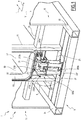
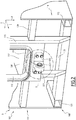
- a set of vehicles 1, 3 comprising a first vehicle 1 ( Figure 1 ), a second vehicle 3 ( Figure 2 ) intended to be coupled to the first vehicle 1 and a coupling device 5 ( Figures 1 and 2 ).
- the first vehicle 1 is a railway vehicle, for example a car or a locomotive, intended to be part of an articulated train (not shown) extending in the longitudinal direction L.
- the Figure 1 is a longitudinal end 7 of the first vehicle 1.
- the first vehicle 1 comprises a median bogie (not shown) located under the longitudinal end 7, it is also called “end carrier".
- the median bogie is for example arranged directly above the coupling device 5 or in the vicinity of the longitudinal end 7, offset towards the inside of the first vehicle 1.
- the first vehicle 1 further comprises a lower chassis 9, an upper chassis 11, vertical uprights 13, 15, a floor 17 and an outer shell 19.
- the lower chassis 9 extends substantially in a horizontal plane and cooperates with the median bogie to support the first vehicle 1.
- the lower chassis 9 comprises in particular two side rails 21, 23 extending substantially in the longitudinal direction L, a crossbar 25 secured to the side rails 21, 23, and a crossbar 27 also integral with the longitudinal members 21, 23 and located under the coupling device 5.
- the crosspiece 25 supports the uprights 13, 15.
- the crossbar 27 is substantially parallel to the cross member 25 and substantially perpendicular to the side rails 21, 23
- the upper frame 11 also extends in a horizontal plane and serves in particular to support the floor 17 of the first vehicle 1. It comprises in particular a cross member 29 substantially perpendicular to the vertical uprights 13, 15.
- the floor 17 comprises a platform 30 for travelers and a corridor 31 interconnecting with the second vehicle 3, the corridor 31 being located in the extension of the platform 30, above the coupling device 5.
- the uprights 13, 15 rest on the crosspiece 25. They are located on either side of the coupling device 5 in the transverse direction T and extend in the vertical direction V to the outer envelope 19.
- the vertical uprights 13, 15 and the crosspieces 25, 29 extend in a plane substantially orthogonal to the longitudinal direction L.
- the outer casing 19 comprises side walls that can include doors and windows (not shown) and a roof (not shown) of the first vehicle 1.
- the second vehicle 3 is also a railway vehicle intended to be part of the articulated train (not shown), for example a car or a locomotive.
- the Figure 2 is a longitudinal end 107 of the second vehicle 3, intended to be vis-à-vis the longitudinal end 7 of the first vehicle 1 so as to allow a coupling of the first and second vehicles 1, 3.
- the second vehicle 3 does not include a median bogie under the longitudinal end 107.
- the longitudinal end 107 is intended to rest on the longitudinal end 7 of the vehicle 1, which is why the longitudinal end 107 is also called “butt”. This means that the longitudinal end 107 is supported by the median bogie via the first vehicle 1.
- the longitudinal end 107 "rests” therefore on the longitudinal end 7 of the first vehicle 1, which "rests” it even on the middle bogie.
- the second vehicle 3 has a structure similar to the first vehicle 1, with a lower frame 109, an upper frame 111, vertical uprights 113, 115, a floor 117, an outer shell 119, two side rails 121, 123, a cross member 125 secured to the side rails 121, 123, a cross member 129, a platform 130, a corridor 131 interconnecting with the first vehicle 1,
- the vertical uprights 113, 115 and the crosspieces 125, 129 extend in a plane substantially orthogonal to the longitudinal direction L.
- the outer shell 119 includes sidewalls that may include doors and windows (not shown) and a roof (not shown) of the second vehicle 3.
- the first vehicle 1 and / or the second vehicle 3 may comprise elements located at the longitudinal ends 7, 107, for example auxiliaries, such as batteries, electrical boxes, pipes or cables. electric.
- auxiliaries such as batteries, electrical boxes, pipes or cables. electric.
- the coupling device 5 ( Figures 1 and 2 ) comprises a first part 201, shown on the Figure 1 attached to the first vehicle 1, a second portion 203, shown in Figure 3, fixed on the second vehicle 3, an articulation 205a, 205b, 205c, 205d, 205e, intended to join the first and second parts 201, 203 and a support member 207 located between the first part 201 and the crossing 27.
- the first part is for example fixed by four bolts to the cross member 29 of the first vehicle 1.
- the first portion 201 generally projects from the cross member 29 in the longitudinal direction L towards the second vehicle 3.
- the first part 201 comprises an energy absorbing component 209, a yoke 211, the energy absorbing component interposed between the yoke 211 and the cross member 29 in the longitudinal direction, and two lateral lugs 213a, 213b located on the side and else of the yoke 211 and the energy absorbing component 209 in the transverse direction T.
- the yoke 211 comprises two substantially parallel branches, extending substantially in a plane orthogonal to the transverse direction T and a median portion connecting the two branches and extending substantially in a plane orthogonal to the longitudinal direction L.
- the yoke 211 has a "U" shape, the "U” developing in a horizontal plane, the opening of the "U” being oriented in the longitudinal direction L towards the second vehicle 3.
- the yoke 211 rests on the support member 207.
- the contact of the yoke 211 with the support member is by a lower edge of the branches and the middle part.
- the substantially parallel branches each comprise a drilling axis substantially parallel to the transverse direction T.
- the middle part of the yoke 211 is fixed on the energy absorbing component 209, itself fixed on the crosspiece 29.
- the energy absorbing component 209 is provided to deform plastically when a compressive force in the longitudinal direction L greater than a predetermined threshold is applied thereto.
- the energy absorbing component 209 can absorb the energy of an impact in the longitudinal direction L, for example if the second vehicle 3 collides with the first vehicle 1, so as to avoid deformation of other parts vehicles 1 and 3.
- the energy absorbing component 209 is made of steel.
- the lateral lugs 213a, 213b extend against the branches of the yoke 211 and against the energy-absorbing component 209 in two planes substantially orthogonal to the transverse direction T.
- the lateral lugs 213a, 213b are fixed on the crossbar 29 and are not integral with the yoke 211 or the energy absorbing component 209.
- the lateral lugs 213a, 213b each comprise a lumen extending in the plane of the concerned lateral ear 213a, 213b.
- the lights are oblong, more elongated in the longitudinal direction L than in the vertical direction V.
- the second part 203 of the coupling device 5 ( Figure 2 ) is fixed to the cross member 129 of the second vehicle 3, for example by four bolts.
- the second part 203 comprises a lug 215 protruding in the longitudinal direction L towards the first vehicle 1.
- the second part 203 is configured and located in such a way that the lug 215 comes to be housed between the branches of the yoke 211 (FIG. Figure 1 ) when the ends 7 and 107 are approaching each other in the longitudinal direction L.
- the tab 215 On a first proximal section, the tab 215 has a rectangular section orthogonal to the longitudinal direction L. On a second distal section, the tab 215 is machined so as to have a rounded end in a plane substantially orthogonal to the transverse direction T.
- the lug 215 further comprises an internal spherical bearing, located substantially at the distal end of the lug 215, the bearing opening on either side of the lug 215 in the transverse direction T.
- the joint 205a, 205b, 205c, 205d, 205e comprises tenons 205a, 205b ( Figure 1 ) engaged in the holes of the branches of the yoke 211 in the transverse direction T, a spherical articulation axis 205c ( Figure 2 ) housed in the spherical bearing of the lug 215 and fasteners 205d, 205e ( Figure 1 ) for fixing the tenons 205a, 205b on the branches of the yoke 211.
- the tenons 205a, 205b pass through the bores of the branches of the yoke 211 in the transverse direction T and each comprise a conical end directed towards the inside of the "U" formed by the yoke 211.
- the spherical articulation axis 205c comprises two tapered bores 217 intended to receive each respectively the conical end of one of the tenons 205a, 205b.
- the spherical articulation axis 205c and / or the spherical bearing of the lug 215 are coated with a material intended to facilitate the sliding of the spherical articulation axis 205c in the spherical bearing of the lug 215.
- the fasteners 205d, 205e are intended to be located on either side of the branches of the yoke 211, outside the "U".
- the fasteners 205d, 205e serve to immobilize the tenons 205a, 205b when engaged in the bores 217.
- fasteners 205d, 205e thanks to a connection with the tenons 205a, 205b, for example by groove and tongue (not shown), are adapted to immobilize the tenons 205a, 205b in rotation in the transverse direction T.
- the fasteners 205d, 205e are also able to cooperate with one another to immobilize the tenons 205a, 205b and the spherical articulation axis 205c in translation in the transverse direction T.
- the fasteners 205d, 205e, in the position of use, are for example screwed into the branches of the yoke 211.
- the support member 207 ( Figure 1 ) extends in the vertical direction V, between the crossbar 27, on which it is fixed, and the yoke 211.
- the support member 207 shaped to withstand vertical forces directed downwards corresponding to a fraction of the weight of the second vehicle 3 bears on the longitudinal end 7 of the first vehicle 1.
- the support member 207 has a chair shape.
- the support member 207 comprises a bottom wall in contact with the cross member 27, an upper wall, substantially parallel to the bottom wall and in contact with the yoke 211, several amounts, for example four, extending in the vertical direction V between the bottom wall and the top wall.
- the support member 207 is for example made of steel.
- the support member 207 and the first part 201 are in contact in a substantially horizontal plane, permanently, or at least when said vertical forces directed downwards corresponding to a fraction of the weight of the second vehicle 3 are transmitted to the first vehicle 1 .
- the contact between the support member 207 and the first part 201 allows a sliding of the yoke 211 on the support member 207 in directions extending in a horizontal plane.
- the coupling device 5 comprises a sliding connection between the support member 207 and the first part 201, the slide connection being substantially oriented in the longitudinal direction L, so as to allow a retraction of the yoke 211 in the longitudinal direction L, especially in the event of impact, without affecting the position of the support member 207 relative to the cross member 27.
- the support member 207 is rigidly connected to the first part 201, for example to the yoke 211, and the support member 207 is deformable so as to absorb a setback of the first part 201 in the longitudinal direction L, due to a shock of the second vehicle 3 on the first vehicle 1.
- first and second vehicles 1 and 3 Before bringing the first and second vehicles 1 and 3 so as to put the ends 7 and 107 vis-a-vis in the longitudinal direction L, it is ensured, on the side of the first vehicle 1 that the tenons 205a, 205b are removed from the branch bores of the yoke 211. On the side of the second vehicle 3, it is ensured that the hinge axis 205c is oriented in the space so that the bores 217 are oriented substantially in the transverse direction T.
- first and second vehicles 1, 3 are brought closer to one another until the lug 215 is housed between the branches of the yoke 211, the bores 217 of the spherical hinge axis 205c. being substantially coaxial with the bores of the branches of the yoke 211.
- each of the tenons 205a, 205b are respectively introduced into the light of one of the ears 213a, 213b and into the drilling of one of the branches of the yoke 211 in the transverse direction T, until each of the tenons 205a, 205b come to rest respectively in one of the conical bores of the spherical articulation axis 205c.
- the tenons 205a, 205b are encapuchonned by the fasteners 205d, 205e which are each respectively fixed on one of the branches of the yoke 211 outside the "U".
- the spherical articulation axis 205c and the tenons 205a, 205b are then integral with the first portion 201 of the coupling device 5.
- the lug 215 can move around the spherical articulation axis 205c which plays a role of patella .
- the first and second portions 201, 203 are linked by a ball joint type connection.
- the longitudinal end 107 of the second vehicle 3 does not rest directly on a bogie, a fraction of the weight of the second vehicle 3 is communicated to the first vehicle 1 in the form of vertical forces, directed downwards, exerted by the second part 203 on the first part 201 of the coupling device 5.
- These vertical forces are mainly taken up by the support member 207.
- majority it is meant that at least 50%, preferably 80%, and even more preferably at least 90%, of the vertical forces are taken up by the support member 207 and communicated to the cross member 27, rather than the cross member 29, via the first part 201 of the coupling device 5.
- the yoke 211 moves back in the longitudinal direction L, advantageously by sliding on the support member 207 in the embodiments allowing such a slip.
- the first and second vehicles 1, 3 are protected to a certain intensity of shock.
- the shock absorbing element 109 acts as a shock control and can be replaced in case of plastic deformation, or plastic deformation beyond a predefined limit.
- the ears 213a, 213b are not integral with the yoke 211, so the retreat of the yoke 211 does not affect them directly.
- the ears 213a, 213b have not been affected by the shock and still enclose the formed assembly by tenons 205a, 205b and fasteners 205d, 205e.
- the ears 213a, 213b are able to maintain the cohesion of the set of vehicles 1, 3, even if the connection between the yoke 211 and the crossbar 29 is no longer ensured.
- the support member 207 resting on a structural element (the cross member 27) of the first vehicle 1, shaped and arranged to support the first portion 201 when a fraction of the weight of the second vehicle 3 is transmitted to the first vehicle 1 via the coupling device 5, the first part 201 transmits only a reduced fraction of the weight of the second vehicle 3 to the cross member 29 of the first vehicle 1, instead of the entire weight of the second vehicle 3 in the absence of support member 207.
- the coupling device 5 is therefore able to take up significant vertical forces, corresponding, for example, to a fraction of the weight of the second vehicle 3. Because the first part 201 transmits only a reduced fraction of the weight of the second vehicle 3 to the transom 29 of the first vehicle 1, the first portion 201 is less massive and can be fixed to the cross member 29 more simply. For example, it is fixed only with four bolts screwed into the crossbar 29.
- the coupling device 5 has a low cost of obtaining and using and is able to take up significant vertical forces corresponding to a fraction of the weight of the second vehicle 3.
- a sliding connection between the support member 207 and the first part 201, the slide connection being substantially oriented in the longitudinal direction L, makes it possible to avoid or limit the deformation of the support member 207 during a shock.
- this effect can be obtained if the support member 207 rigidly connected to the first part 201, is deformable so as to absorb a recoil of the first part 201 in the longitudinal direction L.
- the energy absorbing component 209 located between the joint 205a, 205b, 205c, 205d, 205e and the first vehicle 1, protects the vehicles 1, 3 during an impact.
- the energy absorbing component 209 comprises a metal part, calibrated to plastically deform under a predetermined force exerted in the longitudinal direction L, it can serve as a shock detector, its plastic deformation indicating that a shock of higher intensity at the predetermined threshold occurred. In addition, the energy absorbing component 209 can then be easily replaced by a new undistorted energy absorbing component.
- the ears 213a, 213b make it possible to increase the tensile strength of the set of vehicles 1, 3 after an impact. They act as a safety that doubles the leg assembly 215, articulation 205a, 205b, 205c, 205d, 205e, and clevis 211.
- the cross member 27, on which the support member 207 rests, is an additional device that is both simple and effective for transmitting significant vertical forces, directed downwards, to the structure of the first vehicle 1, for example for transmitting power. a fraction of the weight of the second vehicle 3 to a median bogie of the first vehicle 1, located near the coupling device 5.
- the coupling device 5 is well adapted to a configuration in which the first vehicle 1 comprises a median bogie located under the coupling device 5, or in the vicinity, the middle bogie supporting part of the weight second vehicle 3.
Landscapes
- Engineering & Computer Science (AREA)
- Mechanical Engineering (AREA)
- Transportation (AREA)
- Vibration Dampers (AREA)
- Body Structure For Vehicles (AREA)
Claims (11)
- Fahrzeugeinheit (1, 3), aufweisend ein erstes Fahrzeug (1) und ein zweites Fahrzeug (3), insbesondere Schienenfahrzeuge, von welchen jedes ein Ende (7, 107) in einer Longitudinalrichtung (L) des ersten und zweiten Fahrzeugs (1, 3) aufweist, wobei das erste Fahrzeug (1) ferner ein Strukturelement (27) aufweist, und eine Kupplungsvorrichtung (5) der zwei Fahrzeuge (1, 3), welche aufweist:- einen ersten Teil (201), welcher am Ende (7) des ersten Fahrzeugs (1) in der Longitudinalrichtung (L) fixiert ist,- einen zweiten Teil (203), welcher am Ende (107) des zweiten Fahrzeugs (3) in der Longitudinalrichtung (L) fixiert ist, und- ein Gelenk (205a, 205b, 205c, 205d, 205e), welches eine Kugelgelenkverbindung zwischen dem ersten Teil (201) und dem zweiten Teil (203) bildet,dadurch gekennzeichnet, dass die Kupplungsvorrichtung (5) ferner ein Stützmittel (207) aufweist, welches auf dem Strukturelement (27) des ersten Fahrzeugs (1) gestützt ist, das Stützmittel (207) in einer Art des Stützens des ersten Teils (201) eingerichtet und angeordnet ist, wenn ein Gewichtsanteil des zweiten Fahrzeugs (3) auf das erste Fahrzeug (1) mittels der Kupplungsvorrichtung (5) übertragen wird, das Stützmittel (207) vom ersten Teil (201) separat ist, sich das Stützmittel (207) unterhalb des ersten Teils (201) im Wesentlichen in einer Vertikalrichtung (V) erstreckt, und dass die Fahrzeugeinheit (1, 3) eine Gleitverbindung zwischen dem Stützmittel (207) und dem ersten Teil (201) aufweist, wobei die Gleitverbindung im Wesentlichen in der Longitudinalrichtung (L) orientiert ist.
- Einheit gemäß Anspruch 1, dadurch gekennzeichnet, dass das Stützmittel (207) und der erste Teil (201) in einer im Wesentlichen Horizontalebene in Kontakt sind, wenn der Gewichtsanteil des zweiten Fahrzeugs (3) auf das erste Fahrzeug (1) übertragen wird.
- Einheit gemäß Anspruch 1 oder 2, dadurch gekennzeichnet, dass das Stützmittel (207) mit dem ersten Teil (201) steif verbunden ist und in der Art des Absorbierens eines Zurückbewegens des ersten Teils (201) in der Longitudinalrichtung (L) aufgrund eines Stoßes des zweiten Fahrzeugs (3) auf das erste Fahrzeug (1) verformbar ist.
- Einheit gemäß irgendeinem der Ansprüche 1 bis 3, dadurch gekennzeichnet, dass der erste Teil (201) der Kupplungsvorrichtung (5) eine Energieabsorptionskomponente (209) zum Absorbieren eines Stoßes zwischen dem ersten Fahrzeug (1) und dem zweiten Fahrzeug (3) in der Longitudinalrichtung (L) aufweist, wobei die Energieabsorptionskomponente (209) an der Seite des Gelenks (205a, 205b, 205c, 205d, 205e) entgegengesetzt zum zweiten Teil (203) angeordnet ist.
- Einheit gemäß Anspruch 4, dadurch gekennzeichnet, dass die Energieabsorptionskomponente (209) ein Metallteil aufweist, welches eingestellt ist, um sich unter einer vorbestimmten Belastung zu verformen, welche in der Longitudinalrichtung (L) durch das zweite Fahrzeug (3) auf das erste Fahrzeug (1) mittels der Kupplungsvorrichtung (5) ausgeübt wird.
- Einheit gemäß irgendeinem der Ansprüche 1 bis 5, dadurch gekennzeichnet, dass der erste Teil (201) einen Gabelkopf (211) aufweist, welcher zwei im Wesentlichen parallele Schenkel, die sich im Wesentlichen in einer zu einer Transversalrichtung (T) der zwei Fahrzeuge (1, 3) orthogonalen Ebene erstrecken, die zur Longitudinalrichtung (L) orthogonal ist, und einen Mittelteil aufweist, welcher die zwei Schenkel verbindet und sich im Wesentlichen in einer Ebene erstreckt, welche zur Longitudinalrichtung (L) orthogonal ist, wobei der Gabelkopf (211) auf dem Stützmittel (207) gestützt ist.
- Einheit gemäß Anspruch 6, dadurch gekennzeichnet, dass der zweite Teil (203) eine sich im Wesentlichen in der Longitudinalrichtung (L) erstreckende Lasche (215) aufweist, welche zwischen die zwei Schenkel des Gabelkopfs (211) eingesetzt ist.
- Einheit gemäß Anspruch 7, dadurch gekennzeichnet, dass das Gelenk (205a, 205b, 205c, 205d, 205e) eine Kugelgelenkachse (205c), welche in einem Lager untergebracht ist, das in der Lasche (215) des zweiten Teils (203) vorgesehen ist, Zapfen (205a, 205b) und Befestigungselemente (205d, 205e) zum Verbinden der Kugelgelenkachse (205c) mit den Schenkeln des Gabelkopfs (211) des ersten Teils (201) aufweist.
- Einheit gemäß Anspruch 8, dadurch gekennzeichnet, dass sie ferner zwei Ohren (213a, 213b) aufweist, welche in der Transversalrichtung (T) beidseitig des ersten Teils (201) angeordnet sind und eingerichtet sind, um am ersten Fahrzeug (1) fixiert zu sein, und dass jeder Zapfen (205a, 205b) des Gelenks (205a, 205b, 205c, 205d, 205e) zum einen eine Bohrung, welche an einem der zwei Schenkel des Gabelkopfs (211) im Wesentlichen in der Transversalrichtung (T) ausgeführt ist, und zum anderen eine Öffnung quert, welche in einem der zwei Ohren (213a, 213b) vorgesehen ist, wobei die Öffnungen eine längliche Form in der Art haben, dass in dem Fall eines Stoßes, der eine Verschiebung des ersten Teils (201) und des Gelenks (205a, 205b, 205c, 205d, 205e) in Richtung zum ersten Fahrzeug (1) in der Längsrichtung (L) verursacht, die Zapfen (205a, 205b) und die Befestigungselemente (205d, 205e) in den Öffnungen in der Longitudinalrichtung (L) verschiebbar sind, ohne die Ohren (213a, 213b) zu verformen.
- Einheit gemäß irgendeinem der Ansprüche 1 bis 9, dadurch gekennzeichnet, dass das Strukturelement (27) des ersten Fahrzeugs (1) eine Traverse ist.
- Einheit gemäß irgendeinem der Ansprüche 1 bis 10, dadurch gekennzeichnet, dass das erste Fahrzeug (1) ein Mitteldrehgestell aufweist, welches unter oder in der Nähe der Kupplungsvorrichtung (5) angeordnet ist, wobei ein Teil des Gewichts des zweiten Fahrzeugs (3) auf dem Mitteldrehgestell mittels des Stützmittels (207) der Kupplungsvorrichtung gestützt ist.
Applications Claiming Priority (2)
| Application Number | Priority Date | Filing Date | Title |
|---|---|---|---|
| FR1251796A FR2987332B1 (fr) | 2012-02-28 | 2012-02-28 | Dispositif d'accouplement de deux vehicules, notamment ferroviaires, et ensemble de vehicules correspondant. |
| PCT/EP2013/054068 WO2013127937A1 (fr) | 2012-02-28 | 2013-02-28 | Dispositif d'accouplement de deux véhicules, notamment ferroviaires, et ensemble de véhicules correspondant |
Publications (2)
| Publication Number | Publication Date |
|---|---|
| EP2819905A1 EP2819905A1 (de) | 2015-01-07 |
| EP2819905B1 true EP2819905B1 (de) | 2019-01-16 |
Family
ID=47780063
Family Applications (1)
| Application Number | Title | Priority Date | Filing Date |
|---|---|---|---|
| EP13707163.5A Active EP2819905B1 (de) | 2012-02-28 | 2013-02-28 | Vorrichtung zur kopplung zweier fahrzeuge, insbesondere zweier schienenfahrzeuge, sowie entsprechende anordnung von fahrzeugen |
Country Status (5)
| Country | Link |
|---|---|
| EP (1) | EP2819905B1 (de) |
| ES (1) | ES2719453T3 (de) |
| FR (1) | FR2987332B1 (de) |
| RU (1) | RU2622319C2 (de) |
| WO (1) | WO2013127937A1 (de) |
Family Cites Families (8)
| Publication number | Priority date | Publication date | Assignee | Title |
|---|---|---|---|---|
| US4766818A (en) * | 1985-06-03 | 1988-08-30 | Railmaster System, Inc. | Train of highway trailers and method of making |
| FR2631917B1 (fr) * | 1988-05-24 | 1990-08-10 | Alsthom | Articulation d'accouplement de deux vehicules ferroviaires |
| FR2716149B1 (fr) * | 1994-02-15 | 1996-03-29 | Gec Alsthom Transport Sa | Articulation d'accouplement et procédé d'absorption d'énergie entre deux véhicules ferroviaires. |
| DE19638763C2 (de) * | 1996-09-21 | 2001-02-15 | Daimler Chrysler Ag | Drehgestellanbindung für Jacobs-Drehgestelle |
| FR2769276B1 (fr) * | 1997-10-02 | 2002-10-11 | Gec Alsthom Transport Sa | Articulation d'accouplement |
| DE19919536A1 (de) * | 1999-04-29 | 2000-11-02 | Alstom Lhb Gmbh | Gelenkkupplung für Fahrzeugeinheiten von Schienenfahrzeugen |
| DE102006011425A1 (de) * | 2006-03-11 | 2007-09-13 | Schaeffler Kg | Gelenkkupplung für Schienenfahrzeuge |
| FR2945266A1 (fr) * | 2009-05-06 | 2010-11-12 | Alstom Transport Sa | Articulation d'accouplement entre une premiere voiture et une seconde voiture d'un vehicule notamment ferroviaire |
-
2012
- 2012-02-28 FR FR1251796A patent/FR2987332B1/fr active Active
-
2013
- 2013-02-27 RU RU2013108874A patent/RU2622319C2/ru active
- 2013-02-28 ES ES13707163T patent/ES2719453T3/es active Active
- 2013-02-28 EP EP13707163.5A patent/EP2819905B1/de active Active
- 2013-02-28 WO PCT/EP2013/054068 patent/WO2013127937A1/fr not_active Ceased
Non-Patent Citations (1)
| Title |
|---|
| None * |
Also Published As
| Publication number | Publication date |
|---|---|
| RU2622319C2 (ru) | 2017-06-14 |
| FR2987332A1 (fr) | 2013-08-30 |
| WO2013127937A1 (fr) | 2013-09-06 |
| EP2819905A1 (de) | 2015-01-07 |
| RU2013108874A (ru) | 2014-09-10 |
| FR2987332B1 (fr) | 2014-11-28 |
| ES2719453T3 (es) | 2019-07-10 |
Similar Documents
| Publication | Publication Date | Title |
|---|---|---|
| FR3002898A1 (fr) | Vehicule automobile routier comportant un amortisseur de chocs escamotable | |
| EP3113597B1 (de) | Vorrichtung zum anhängen eines werkzeugs, wie etwa ein landwirtschaftliches werkzeug, an ein zugsystem eines fahrzeugs, wie etwa ein landwirtschaftlicher traktor | |
| FR2887211A1 (fr) | Voie basse guidee pour avant de vehicule automobile | |
| CA2701929C (fr) | Articulation d'accouplement entre une premiere voiture et une seconde voiture d'un vehicule notamment ferroviaire | |
| EP1423287B1 (de) | Hinterachse für ein kraftfahrzeug mit gezogenen aufhängungslenkern und querführungsstangen | |
| EP1827943B1 (de) | Stossdämpfungsvorrichtung für eisenbahnfahrzeug | |
| EP3755605A1 (de) | Fahrzeug mit mindestens einem ablenker im zusammenhang mit einem dämpfer zur reaktion auf eine frontalkollision mit geringer überdeckung | |
| FR2934233A1 (fr) | Element de renfort lateral de l'avant d'une caisse de vehicule automobile. | |
| WO2013127937A1 (fr) | Dispositif d'accouplement de deux véhicules, notamment ferroviaires, et ensemble de véhicules correspondant | |
| EP3059137B1 (de) | Dämpfungseinrichtung für die kupplungseinrichtung eines eisenbahnfahrzeugs | |
| FR2801554A1 (fr) | Dispositif de deformation controlee sous efforts ou d'absorption d'energie par deformation, notamment deflecteur d'obstacles pour vehicule ferroviaire | |
| EP2836378B1 (de) | Befestigung einer abschleppvorrichtung mit einem kraftverteilungsträger | |
| WO2015025101A1 (fr) | Renfort de tunnel de plancher de vehicule automobile | |
| EP3362334B1 (de) | Kraftfahrzeug-strukturbauteil und vorderen unterbereich mit einem solchen bauteil | |
| FR2612145A1 (fr) | Dispositif d'accrochage adaptable sur des boggies ferroviaires pour l'accouplement entre deux remorques de transport routier | |
| EP4037957B1 (de) | Seitenaufpralldämpfer für ein kraftfahrzeug | |
| WO2000064723A1 (fr) | Dispositif d'accouplement pour wagons de chemins de fer | |
| EP3339143B1 (de) | Anordnung für karosseriestruktur eines kraftfahrzeugs, die einen stossdämpfer umfasst | |
| EP0767079B1 (de) | Trägerbalken für Anhänger | |
| EP3736184B1 (de) | Fahrzeug, das mit einer schutzvorrichtung für die beine des fahrers ausgestattet ist | |
| EP3110665B1 (de) | Kraftfahrzeug mit einklappbarem stossdämpfer | |
| FR3033764A1 (fr) | Dispositif formant marchepied d'un vehicule automobile | |
| EP4450360A1 (de) | Schienenfahrzeug mit verbesserter gelenkvorrichtung | |
| FR2477490A1 (fr) | Etrier guide pour amortisseur | |
| BE563501A (de) |
Legal Events
| Date | Code | Title | Description |
|---|---|---|---|
| PUAI | Public reference made under article 153(3) epc to a published international application that has entered the european phase |
Free format text: ORIGINAL CODE: 0009012 |
|
| 17P | Request for examination filed |
Effective date: 20140929 |
|
| AK | Designated contracting states |
Kind code of ref document: A1 Designated state(s): AL AT BE BG CH CY CZ DE DK EE ES FI FR GB GR HR HU IE IS IT LI LT LU LV MC MK MT NL NO PL PT RO RS SE SI SK SM TR |
|
| AX | Request for extension of the european patent |
Extension state: BA ME |
|
| DAX | Request for extension of the european patent (deleted) | ||
| RAP1 | Party data changed (applicant data changed or rights of an application transferred) |
Owner name: ALSTOM TRANSPORT TECHNOLOGIES |
|
| GRAP | Despatch of communication of intention to grant a patent |
Free format text: ORIGINAL CODE: EPIDOSNIGR1 |
|
| STAA | Information on the status of an ep patent application or granted ep patent |
Free format text: STATUS: GRANT OF PATENT IS INTENDED |
|
| INTG | Intention to grant announced |
Effective date: 20180808 |
|
| GRAS | Grant fee paid |
Free format text: ORIGINAL CODE: EPIDOSNIGR3 |
|
| GRAA | (expected) grant |
Free format text: ORIGINAL CODE: 0009210 |
|
| STAA | Information on the status of an ep patent application or granted ep patent |
Free format text: STATUS: THE PATENT HAS BEEN GRANTED |
|
| AK | Designated contracting states |
Kind code of ref document: B1 Designated state(s): AL AT BE BG CH CY CZ DE DK EE ES FI FR GB GR HR HU IE IS IT LI LT LU LV MC MK MT NL NO PL PT RO RS SE SI SK SM TR |
|
| REG | Reference to a national code |
Ref country code: GB Ref legal event code: FG4D Free format text: NOT ENGLISH |
|
| REG | Reference to a national code |
Ref country code: CH Ref legal event code: EP |
|
| REG | Reference to a national code |
Ref country code: IE Ref legal event code: FG4D Free format text: LANGUAGE OF EP DOCUMENT: FRENCH |
|
| REG | Reference to a national code |
Ref country code: DE Ref legal event code: R096 Ref document number: 602013049849 Country of ref document: DE |
|
| REG | Reference to a national code |
Ref country code: AT Ref legal event code: REF Ref document number: 1089494 Country of ref document: AT Kind code of ref document: T Effective date: 20190215 |
|
| REG | Reference to a national code |
Ref country code: CH Ref legal event code: NV Representative=s name: MICHELI AND CIE SA, CH |
|
| REG | Reference to a national code |
Ref country code: NL Ref legal event code: MP Effective date: 20190116 |
|
| REG | Reference to a national code |
Ref country code: LT Ref legal event code: MG4D |
|
| PG25 | Lapsed in a contracting state [announced via postgrant information from national office to epo] |
Ref country code: NL Free format text: LAPSE BECAUSE OF FAILURE TO SUBMIT A TRANSLATION OF THE DESCRIPTION OR TO PAY THE FEE WITHIN THE PRESCRIBED TIME-LIMIT Effective date: 20190116 |
|
| REG | Reference to a national code |
Ref country code: ES Ref legal event code: FG2A Ref document number: 2719453 Country of ref document: ES Kind code of ref document: T3 Effective date: 20190710 |
|
| REG | Reference to a national code |
Ref country code: AT Ref legal event code: MK05 Ref document number: 1089494 Country of ref document: AT Kind code of ref document: T Effective date: 20190116 |
|
| PG25 | Lapsed in a contracting state [announced via postgrant information from national office to epo] |
Ref country code: LT Free format text: LAPSE BECAUSE OF FAILURE TO SUBMIT A TRANSLATION OF THE DESCRIPTION OR TO PAY THE FEE WITHIN THE PRESCRIBED TIME-LIMIT Effective date: 20190116 Ref country code: FI Free format text: LAPSE BECAUSE OF FAILURE TO SUBMIT A TRANSLATION OF THE DESCRIPTION OR TO PAY THE FEE WITHIN THE PRESCRIBED TIME-LIMIT Effective date: 20190116 Ref country code: NO Free format text: LAPSE BECAUSE OF FAILURE TO SUBMIT A TRANSLATION OF THE DESCRIPTION OR TO PAY THE FEE WITHIN THE PRESCRIBED TIME-LIMIT Effective date: 20190416 Ref country code: SE Free format text: LAPSE BECAUSE OF FAILURE TO SUBMIT A TRANSLATION OF THE DESCRIPTION OR TO PAY THE FEE WITHIN THE PRESCRIBED TIME-LIMIT Effective date: 20190116 Ref country code: PL Free format text: LAPSE BECAUSE OF FAILURE TO SUBMIT A TRANSLATION OF THE DESCRIPTION OR TO PAY THE FEE WITHIN THE PRESCRIBED TIME-LIMIT Effective date: 20190116 Ref country code: PT Free format text: LAPSE BECAUSE OF FAILURE TO SUBMIT A TRANSLATION OF THE DESCRIPTION OR TO PAY THE FEE WITHIN THE PRESCRIBED TIME-LIMIT Effective date: 20190516 |
|
| PG25 | Lapsed in a contracting state [announced via postgrant information from national office to epo] |
Ref country code: LV Free format text: LAPSE BECAUSE OF FAILURE TO SUBMIT A TRANSLATION OF THE DESCRIPTION OR TO PAY THE FEE WITHIN THE PRESCRIBED TIME-LIMIT Effective date: 20190116 Ref country code: RS Free format text: LAPSE BECAUSE OF FAILURE TO SUBMIT A TRANSLATION OF THE DESCRIPTION OR TO PAY THE FEE WITHIN THE PRESCRIBED TIME-LIMIT Effective date: 20190116 Ref country code: BG Free format text: LAPSE BECAUSE OF FAILURE TO SUBMIT A TRANSLATION OF THE DESCRIPTION OR TO PAY THE FEE WITHIN THE PRESCRIBED TIME-LIMIT Effective date: 20190416 Ref country code: GR Free format text: LAPSE BECAUSE OF FAILURE TO SUBMIT A TRANSLATION OF THE DESCRIPTION OR TO PAY THE FEE WITHIN THE PRESCRIBED TIME-LIMIT Effective date: 20190417 Ref country code: IS Free format text: LAPSE BECAUSE OF FAILURE TO SUBMIT A TRANSLATION OF THE DESCRIPTION OR TO PAY THE FEE WITHIN THE PRESCRIBED TIME-LIMIT Effective date: 20190516 Ref country code: HR Free format text: LAPSE BECAUSE OF FAILURE TO SUBMIT A TRANSLATION OF THE DESCRIPTION OR TO PAY THE FEE WITHIN THE PRESCRIBED TIME-LIMIT Effective date: 20190116 |
|
| REG | Reference to a national code |
Ref country code: DE Ref legal event code: R097 Ref document number: 602013049849 Country of ref document: DE |
|
| PG25 | Lapsed in a contracting state [announced via postgrant information from national office to epo] |
Ref country code: AT Free format text: LAPSE BECAUSE OF FAILURE TO SUBMIT A TRANSLATION OF THE DESCRIPTION OR TO PAY THE FEE WITHIN THE PRESCRIBED TIME-LIMIT Effective date: 20190116 Ref country code: DK Free format text: LAPSE BECAUSE OF FAILURE TO SUBMIT A TRANSLATION OF THE DESCRIPTION OR TO PAY THE FEE WITHIN THE PRESCRIBED TIME-LIMIT Effective date: 20190116 Ref country code: MC Free format text: LAPSE BECAUSE OF FAILURE TO SUBMIT A TRANSLATION OF THE DESCRIPTION OR TO PAY THE FEE WITHIN THE PRESCRIBED TIME-LIMIT Effective date: 20190116 Ref country code: AL Free format text: LAPSE BECAUSE OF FAILURE TO SUBMIT A TRANSLATION OF THE DESCRIPTION OR TO PAY THE FEE WITHIN THE PRESCRIBED TIME-LIMIT Effective date: 20190116 Ref country code: SK Free format text: LAPSE BECAUSE OF FAILURE TO SUBMIT A TRANSLATION OF THE DESCRIPTION OR TO PAY THE FEE WITHIN THE PRESCRIBED TIME-LIMIT Effective date: 20190116 Ref country code: EE Free format text: LAPSE BECAUSE OF FAILURE TO SUBMIT A TRANSLATION OF THE DESCRIPTION OR TO PAY THE FEE WITHIN THE PRESCRIBED TIME-LIMIT Effective date: 20190116 Ref country code: CZ Free format text: LAPSE BECAUSE OF FAILURE TO SUBMIT A TRANSLATION OF THE DESCRIPTION OR TO PAY THE FEE WITHIN THE PRESCRIBED TIME-LIMIT Effective date: 20190116 Ref country code: LU Free format text: LAPSE BECAUSE OF NON-PAYMENT OF DUE FEES Effective date: 20190228 Ref country code: RO Free format text: LAPSE BECAUSE OF FAILURE TO SUBMIT A TRANSLATION OF THE DESCRIPTION OR TO PAY THE FEE WITHIN THE PRESCRIBED TIME-LIMIT Effective date: 20190116 |
|
| REG | Reference to a national code |
Ref country code: BE Ref legal event code: MM Effective date: 20190228 |
|
| PLBE | No opposition filed within time limit |
Free format text: ORIGINAL CODE: 0009261 |
|
| STAA | Information on the status of an ep patent application or granted ep patent |
Free format text: STATUS: NO OPPOSITION FILED WITHIN TIME LIMIT |
|
| REG | Reference to a national code |
Ref country code: IE Ref legal event code: MM4A |
|
| PG25 | Lapsed in a contracting state [announced via postgrant information from national office to epo] |
Ref country code: SM Free format text: LAPSE BECAUSE OF FAILURE TO SUBMIT A TRANSLATION OF THE DESCRIPTION OR TO PAY THE FEE WITHIN THE PRESCRIBED TIME-LIMIT Effective date: 20190116 |
|
| 26N | No opposition filed |
Effective date: 20191017 |
|
| GBPC | Gb: european patent ceased through non-payment of renewal fee |
Effective date: 20190416 |
|
| PG25 | Lapsed in a contracting state [announced via postgrant information from national office to epo] |
Ref country code: GB Free format text: LAPSE BECAUSE OF NON-PAYMENT OF DUE FEES Effective date: 20190416 Ref country code: IE Free format text: LAPSE BECAUSE OF NON-PAYMENT OF DUE FEES Effective date: 20190228 |
|
| PG25 | Lapsed in a contracting state [announced via postgrant information from national office to epo] |
Ref country code: BE Free format text: LAPSE BECAUSE OF NON-PAYMENT OF DUE FEES Effective date: 20190228 Ref country code: SI Free format text: LAPSE BECAUSE OF FAILURE TO SUBMIT A TRANSLATION OF THE DESCRIPTION OR TO PAY THE FEE WITHIN THE PRESCRIBED TIME-LIMIT Effective date: 20190116 |
|
| PG25 | Lapsed in a contracting state [announced via postgrant information from national office to epo] |
Ref country code: TR Free format text: LAPSE BECAUSE OF FAILURE TO SUBMIT A TRANSLATION OF THE DESCRIPTION OR TO PAY THE FEE WITHIN THE PRESCRIBED TIME-LIMIT Effective date: 20190116 |
|
| PG25 | Lapsed in a contracting state [announced via postgrant information from national office to epo] |
Ref country code: MT Free format text: LAPSE BECAUSE OF FAILURE TO SUBMIT A TRANSLATION OF THE DESCRIPTION OR TO PAY THE FEE WITHIN THE PRESCRIBED TIME-LIMIT Effective date: 20190116 |
|
| PG25 | Lapsed in a contracting state [announced via postgrant information from national office to epo] |
Ref country code: CY Free format text: LAPSE BECAUSE OF FAILURE TO SUBMIT A TRANSLATION OF THE DESCRIPTION OR TO PAY THE FEE WITHIN THE PRESCRIBED TIME-LIMIT Effective date: 20190116 |
|
| PG25 | Lapsed in a contracting state [announced via postgrant information from national office to epo] |
Ref country code: HU Free format text: LAPSE BECAUSE OF FAILURE TO SUBMIT A TRANSLATION OF THE DESCRIPTION OR TO PAY THE FEE WITHIN THE PRESCRIBED TIME-LIMIT; INVALID AB INITIO Effective date: 20130228 |
|
| PG25 | Lapsed in a contracting state [announced via postgrant information from national office to epo] |
Ref country code: MK Free format text: LAPSE BECAUSE OF FAILURE TO SUBMIT A TRANSLATION OF THE DESCRIPTION OR TO PAY THE FEE WITHIN THE PRESCRIBED TIME-LIMIT Effective date: 20190116 |
|
| P01 | Opt-out of the competence of the unified patent court (upc) registered |
Effective date: 20230823 |
|
| REG | Reference to a national code |
Ref country code: ES Ref legal event code: PC2A Owner name: ALSTOM HOLDINGS Effective date: 20250310 |
|
| REG | Reference to a national code |
Ref country code: CH Ref legal event code: U11 Free format text: ST27 STATUS EVENT CODE: U-0-0-U10-U11 (AS PROVIDED BY THE NATIONAL OFFICE) Effective date: 20260301 |
|
| PGFP | Annual fee paid to national office [announced via postgrant information from national office to epo] |
Ref country code: DE Payment date: 20260218 Year of fee payment: 14 |
|
| PGFP | Annual fee paid to national office [announced via postgrant information from national office to epo] |
Ref country code: IT Payment date: 20260224 Year of fee payment: 14 |
|
| PGFP | Annual fee paid to national office [announced via postgrant information from national office to epo] |
Ref country code: FR Payment date: 20260218 Year of fee payment: 14 |
|
| PGFP | Annual fee paid to national office [announced via postgrant information from national office to epo] |
Ref country code: CH Payment date: 20260301 Year of fee payment: 14 |
|
| PGFP | Annual fee paid to national office [announced via postgrant information from national office to epo] |
Ref country code: ES Payment date: 20260408 Year of fee payment: 14 |