EP2820198B1 - Modulare wandinterne funktionsleitungen - Google Patents
Modulare wandinterne funktionsleitungen Download PDFInfo
- Publication number
- EP2820198B1 EP2820198B1 EP13754328.6A EP13754328A EP2820198B1 EP 2820198 B1 EP2820198 B1 EP 2820198B1 EP 13754328 A EP13754328 A EP 13754328A EP 2820198 B1 EP2820198 B1 EP 2820198B1
- Authority
- EP
- European Patent Office
- Prior art keywords
- modular
- wall module
- conduit
- functional
- functional wall
- Prior art date
- Legal status (The legal status is an assumption and is not a legal conclusion. Google has not performed a legal analysis and makes no representation as to the accuracy of the status listed.)
- Not-in-force
Links
- 239000012530 fluid Substances 0.000 claims description 114
- 238000009434 installation Methods 0.000 claims description 33
- 238000000034 method Methods 0.000 claims description 23
- 230000008878 coupling Effects 0.000 claims description 14
- 238000010168 coupling process Methods 0.000 claims description 14
- 238000005859 coupling reaction Methods 0.000 claims description 14
- 239000007789 gas Substances 0.000 description 10
- XLYOFNOQVPJJNP-UHFFFAOYSA-N water Substances O XLYOFNOQVPJJNP-UHFFFAOYSA-N 0.000 description 9
- 239000000463 material Substances 0.000 description 8
- 238000005192 partition Methods 0.000 description 8
- 230000008859 change Effects 0.000 description 7
- 230000008901 benefit Effects 0.000 description 5
- 238000010438 heat treatment Methods 0.000 description 5
- 239000007788 liquid Substances 0.000 description 4
- VNWKTOKETHGBQD-UHFFFAOYSA-N methane Chemical compound C VNWKTOKETHGBQD-UHFFFAOYSA-N 0.000 description 4
- 230000008520 organization Effects 0.000 description 4
- 239000003570 air Substances 0.000 description 3
- 238000004378 air conditioning Methods 0.000 description 3
- 239000004744 fabric Substances 0.000 description 3
- 230000000670 limiting effect Effects 0.000 description 3
- 238000009428 plumbing Methods 0.000 description 3
- 230000008439 repair process Effects 0.000 description 3
- 229920001169 thermoplastic Polymers 0.000 description 3
- 239000004416 thermosoftening plastic Substances 0.000 description 3
- IJGRMHOSHXDMSA-UHFFFAOYSA-N Atomic nitrogen Chemical compound N#N IJGRMHOSHXDMSA-UHFFFAOYSA-N 0.000 description 2
- 229910052782 aluminium Inorganic materials 0.000 description 2
- XAGFODPZIPBFFR-UHFFFAOYSA-N aluminium Chemical compound [Al] XAGFODPZIPBFFR-UHFFFAOYSA-N 0.000 description 2
- 238000004891 communication Methods 0.000 description 2
- 230000001143 conditioned effect Effects 0.000 description 2
- 238000001816 cooling Methods 0.000 description 2
- 238000001125 extrusion Methods 0.000 description 2
- 239000000203 mixture Substances 0.000 description 2
- 239000003345 natural gas Substances 0.000 description 2
- 229920000642 polymer Polymers 0.000 description 2
- CURLTUGMZLYLDI-UHFFFAOYSA-N Carbon dioxide Chemical compound O=C=O CURLTUGMZLYLDI-UHFFFAOYSA-N 0.000 description 1
- RYGMFSIKBFXOCR-UHFFFAOYSA-N Copper Chemical compound [Cu] RYGMFSIKBFXOCR-UHFFFAOYSA-N 0.000 description 1
- 229910000831 Steel Inorganic materials 0.000 description 1
- 230000000712 assembly Effects 0.000 description 1
- 238000000429 assembly Methods 0.000 description 1
- QVGXLLKOCUKJST-UHFFFAOYSA-N atomic oxygen Chemical compound [O] QVGXLLKOCUKJST-UHFFFAOYSA-N 0.000 description 1
- 230000005465 channeling Effects 0.000 description 1
- 238000010276 construction Methods 0.000 description 1
- 229910052802 copper Inorganic materials 0.000 description 1
- 239000010949 copper Substances 0.000 description 1
- 238000010586 diagram Methods 0.000 description 1
- 238000007599 discharging Methods 0.000 description 1
- 238000000605 extraction Methods 0.000 description 1
- 238000001914 filtration Methods 0.000 description 1
- 239000003292 glue Substances 0.000 description 1
- 238000002955 isolation Methods 0.000 description 1
- 238000012423 maintenance Methods 0.000 description 1
- 230000007246 mechanism Effects 0.000 description 1
- 229910052751 metal Inorganic materials 0.000 description 1
- 239000002184 metal Substances 0.000 description 1
- 239000007769 metal material Substances 0.000 description 1
- 238000002156 mixing Methods 0.000 description 1
- 229910052757 nitrogen Inorganic materials 0.000 description 1
- 239000013307 optical fiber Substances 0.000 description 1
- 239000001301 oxygen Substances 0.000 description 1
- 229910052760 oxygen Inorganic materials 0.000 description 1
- 230000036961 partial effect Effects 0.000 description 1
- 239000004033 plastic Substances 0.000 description 1
- 229920003023 plastic Polymers 0.000 description 1
- 230000000135 prohibitive effect Effects 0.000 description 1
- 238000004064 recycling Methods 0.000 description 1
- 230000002829 reductive effect Effects 0.000 description 1
- 230000004044 response Effects 0.000 description 1
- 230000002441 reversible effect Effects 0.000 description 1
- 230000001932 seasonal effect Effects 0.000 description 1
- 238000000638 solvent extraction Methods 0.000 description 1
- 239000010959 steel Substances 0.000 description 1
- 239000002351 wastewater Substances 0.000 description 1
Images


Classifications
-
- E—FIXED CONSTRUCTIONS
- E04—BUILDING
- E04B—GENERAL BUILDING CONSTRUCTIONS; WALLS, e.g. PARTITIONS; ROOFS; FLOORS; CEILINGS; INSULATION OR OTHER PROTECTION OF BUILDINGS
- E04B2/00—Walls, e.g. partitions, for buildings; Wall construction with regard to insulation; Connections specially adapted to walls
- E04B2/74—Removable non-load-bearing partitions; Partitions with a free upper edge
- E04B2/7407—Removable non-load-bearing partitions; Partitions with a free upper edge assembled using frames with infill panels or coverings only; made-up of panels and a support structure incorporating posts
- E04B2/7448—Removable non-load-bearing partitions; Partitions with a free upper edge assembled using frames with infill panels or coverings only; made-up of panels and a support structure incorporating posts with separate framed panels without intermediary posts, extending from floor to ceiling
-
- E—FIXED CONSTRUCTIONS
- E04—BUILDING
- E04B—GENERAL BUILDING CONSTRUCTIONS; WALLS, e.g. PARTITIONS; ROOFS; FLOORS; CEILINGS; INSULATION OR OTHER PROTECTION OF BUILDINGS
- E04B2/00—Walls, e.g. partitions, for buildings; Wall construction with regard to insulation; Connections specially adapted to walls
- E04B2/74—Removable non-load-bearing partitions; Partitions with a free upper edge
- E04B2/7407—Removable non-load-bearing partitions; Partitions with a free upper edge assembled using frames with infill panels or coverings only; made-up of panels and a support structure incorporating posts
-
- E—FIXED CONSTRUCTIONS
- E04—BUILDING
- E04B—GENERAL BUILDING CONSTRUCTIONS; WALLS, e.g. PARTITIONS; ROOFS; FLOORS; CEILINGS; INSULATION OR OTHER PROTECTION OF BUILDINGS
- E04B1/00—Constructions in general; Structures which are not restricted either to walls, e.g. partitions, or floors or ceilings or roofs
- E04B1/343—Structures characterised by movable, separable, or collapsible parts, e.g. for transport
- E04B1/34315—Structures characterised by movable, separable, or collapsible parts, e.g. for transport characterised by separable parts
- E04B1/34326—Structures characterised by movable, separable, or collapsible parts, e.g. for transport characterised by separable parts mainly constituted by longitudinal elements
-
- E—FIXED CONSTRUCTIONS
- E04—BUILDING
- E04B—GENERAL BUILDING CONSTRUCTIONS; WALLS, e.g. PARTITIONS; ROOFS; FLOORS; CEILINGS; INSULATION OR OTHER PROTECTION OF BUILDINGS
- E04B1/00—Constructions in general; Structures which are not restricted either to walls, e.g. partitions, or floors or ceilings or roofs
- E04B1/343—Structures characterised by movable, separable, or collapsible parts, e.g. for transport
- E04B1/34384—Assembling details for foldable, separable, collapsible or retractable structures
-
- F—MECHANICAL ENGINEERING; LIGHTING; HEATING; WEAPONS; BLASTING
- F24—HEATING; RANGES; VENTILATING
- F24F—AIR-CONDITIONING; AIR-HUMIDIFICATION; VENTILATION; USE OF AIR CURRENTS FOR SCREENING
- F24F13/00—Details common to, or for air-conditioning, air-humidification, ventilation or use of air currents for screening
- F24F13/02—Ducting arrangements
- F24F13/0227—Ducting arrangements using parts of the building, e.g. air ducts inside the floor, walls or ceiling of a building
-
- E—FIXED CONSTRUCTIONS
- E04—BUILDING
- E04B—GENERAL BUILDING CONSTRUCTIONS; WALLS, e.g. PARTITIONS; ROOFS; FLOORS; CEILINGS; INSULATION OR OTHER PROTECTION OF BUILDINGS
- E04B2/00—Walls, e.g. partitions, for buildings; Wall construction with regard to insulation; Connections specially adapted to walls
- E04B2/02—Walls, e.g. partitions, for buildings; Wall construction with regard to insulation; Connections specially adapted to walls built-up from layers of building elements
- E04B2/14—Walls having cavities in, but not between, the elements, i.e. each cavity being enclosed by at least four sides forming part of one single element
-
- E—FIXED CONSTRUCTIONS
- E04—BUILDING
- E04B—GENERAL BUILDING CONSTRUCTIONS; WALLS, e.g. PARTITIONS; ROOFS; FLOORS; CEILINGS; INSULATION OR OTHER PROTECTION OF BUILDINGS
- E04B2/00—Walls, e.g. partitions, for buildings; Wall construction with regard to insulation; Connections specially adapted to walls
- E04B2/74—Removable non-load-bearing partitions; Partitions with a free upper edge
- E04B2002/7461—Details of connection of sheet panels to frame or posts
- E04B2002/7462—Details of connection of sheet panels to frame or posts using resilient connectors, e.g. clips
-
- E—FIXED CONSTRUCTIONS
- E04—BUILDING
- E04B—GENERAL BUILDING CONSTRUCTIONS; WALLS, e.g. PARTITIONS; ROOFS; FLOORS; CEILINGS; INSULATION OR OTHER PROTECTION OF BUILDINGS
- E04B2/00—Walls, e.g. partitions, for buildings; Wall construction with regard to insulation; Connections specially adapted to walls
- E04B2/74—Removable non-load-bearing partitions; Partitions with a free upper edge
- E04B2002/7488—Details of wiring
-
- E—FIXED CONSTRUCTIONS
- E04—BUILDING
- E04C—STRUCTURAL ELEMENTS; BUILDING MATERIALS
- E04C1/00—Building elements of block or other shape for the construction of parts of buildings
- E04C1/39—Building elements of block or other shape for the construction of parts of buildings characterised by special adaptations, e.g. serving for locating conduits, for forming soffits, cornices, or shelves, for fixing wall-plates or door-frames, for claustra
-
- E—FIXED CONSTRUCTIONS
- E04—BUILDING
- E04C—STRUCTURAL ELEMENTS; BUILDING MATERIALS
- E04C3/00—Structural elongated elements designed for load-supporting
- E04C3/02—Joists; Girders, trusses, or trusslike structures, e.g. prefabricated; Lintels; Transoms; Braces
- E04C3/04—Joists; Girders, trusses, or trusslike structures, e.g. prefabricated; Lintels; Transoms; Braces of metal
- E04C2003/0404—Joists; Girders, trusses, or trusslike structures, e.g. prefabricated; Lintels; Transoms; Braces of metal beams, girders, or joists characterised by cross-sectional aspects
- E04C2003/0443—Joists; Girders, trusses, or trusslike structures, e.g. prefabricated; Lintels; Transoms; Braces of metal beams, girders, or joists characterised by cross-sectional aspects characterised by substantial shape of the cross-section
- E04C2003/0452—H- or I-shaped
Definitions
- This invention relates to systems, methods, and apparatus for providing modular and/or local conduits capable of fluid delivery and extraction.
- Office space can be relatively expensive due to the basic costs of the location and size of the office space. In addition to these costs, an organization may incur further expense configuring the office space in a desirable layout. An organization might purchase or rent a large open space in a building, and then subdivide or partition the open space into various offices, conference rooms, or cubicles. Rather than having to find new office space and move as an organization's needs change, it is often desirable to reconfigure the existing office space. Many organizations address their configuration and reconfiguration issues by dividing large, open office spaces into individual work areas using modular wall segments and partitions.
- modular systems are relatively easy to configure.
- modular systems can be less expensive to set up and can allow for reconfiguration more easily than more permanently constructed office dividers. For example, a set of offices and a conference area can be carved out of a larger space in a relatively short period of time with the use of modular systems. If office space needs change, the organization can readily reconfigure the space.
- modular office partitions typically include a series of individual wall modules (and/or panels).
- the individual wall modules are typically free-standing or rigidly attached to one or more support structures.
- the wall modules are typically designed to provide a wide variety of potential configurations.
- a manufacturer or assembler can usually align and join the various wall modules together in almost any particular design. These designs can include anything from large conference spaces to individual offices.
- Document US 2002/0104271 A1 discloses a modular patient room for installation in a healthcare facility having gas supply lines, electrical supply lines and water supply lines and includes wall panels having oppositely facing spaced apart wall surfaces, oppositely facing spaced apart side walls configured for joining to the side wall of another wall panel, a top surface, a bottom surface, and an interior.
- One of the wall panel includes a conduit having a first end extending through a wall surface of the wall panel and a second end separated from the first end by an internal portion disposed in the interior of wall panel, the second end extending through one of the sidewalls, top surface, and bottom surface and being configured for connection to one of the gas, electrical and water supply lines.
- the modular patient room may also include couplings in the side walls connected to the second end of the conduit, the couplings being designed and arranged to couple conduits of abutting wall panels.
- Various configurations of modular wall panels may be provided, including an electrical/gas panel and one or more gas outlets plumbed therein.
- Document US 5,953,871 A describes a modular wall panel ready for installation in a medical facility, the panel having at least one medical gas conduit positioned therein.
- the modular wall panel has a pair of opposed side sections and a frame to support each of the side sections.
- the panel has a pair of longitudinal edge regions, the frame including a generally upright frame portion extending along each of the longitudinal edge regions to form a passage therealong for engagement with an adjacent wall panel.
- the spacing between the upright frame portions and the spacing between the opposed side sections together define an inner cavity.
- EP 1 538 272 A1 relates to an improved sound-insulating partition wall.
- EP 1 538 272 A1 also relates to an assembly method for such a wall.
- Document WO 82/00190 A1 is directed to reducing cost incurred by energy loss through warm air by using an air recycling device having an elongate duct means and a means for drawing air into the duct means at one end and discharging air from the duct means at the other end, the elongate duct means having substantially parallel first and second panels joined by side panels inclined to each of the panels.
- An implementation according to the invention includes a functional wall module for at least partially forming an individual space and for providing fluids into the individual space or for removing fluids therefrom.
- the functional wall module has one or more vertical supports and one or more horizontal supports secured to at least one of the one or more vertical supports.
- the functional wall module has a modular conduit system coupled to at least one of the one or more vertical support and the one or more horizontal supports.
- the modular conduit system includes a modular conduit sized and configured for one or more of delivering fluids to the individual space and extracting fluids from the individual space.
- the modular conduit includes one or more vertical conduit supports coupled to and at least partially supporting the modular conduit, the one or more vertical conduit supports further being coupled to at least one of the one or more vertical supports and one or more horizontal supports.
- the modular conduit includes at least one register that is vertically repositionable within the modular conduit, allowing the register to be moved by a user from a first vertical position to a second different vertical position in the modular conduit system, the register incorporating one or more seals that channel the flow of fluid through the register.
- the functional wall module permits users or occupants of the building to control temperature, humidity, air circulation, and air quality, etc. within the individual spaces in the building.
- Implementations of the present invention provide systems, methods, and apparatus for delivering and/or removing fluid from a discrete location within a building.
- at least one implementation includes a modular conduit system that can supply or remove air, water, gas, or other fluids to/from an individual space created by modular walls.
- a functional wall module includes one or more modular conduit systems.
- the modular conduit system within a modular wall i.e., a wall comprising of one or more wall modules) channels the fluid into and/or out of an individual space.
- Additional implementations include a modular wall installation for creating an individual space that has fluid delivery thereto and/or fluid removal therefrom.
- the modular wall installation incorporates one or more wall modules selectively and detachably coupled together.
- the one or more wall modules form the individual space.
- the one or more modules also include at least one functional wall module having a frame and a modular conduit system secured to or within the frame of the functional wall module, wherein the at least one functional wall module conveys fluid into the individual space or removes fluid from the individual space.
- Another implementation of the present invention includes a method of setting up a modular wall installation capable of selective configuration and reconfiguration and further capable of conveying fluid to as well as removing fluid from an individual space.
- the method includes assembling a frame of a first functional wall module and securing a modular conduit system to or within the frame of the first functional wall module.
- the method also includes securing one or more panels to the frame of the first functional wall module.
- the method includes selectively coupling the first functional wall module to one or more wall modules, thereby forming the individual space, wherein the one or more wall modules comprise one or more of a second functional wall module. Additionally a plain wall module can be added to the one or more wall modules.
- the modular conduit includes at least one register that is vertically repositionable within the modular conduit, allowing the register to be moved by a user of the individual space from a first vertical position to a second different vertical position in the modular conduit system, the register incorporating one or more seals that channel the flow of fluid through the register.
- Implementations of the present invention provide systems, methods, and apparatus for delivering and/or removing fluid from a discrete location within a building.
- a modular conduit system that can supply or remove air, water, gas, or other fluids to/from an individual space created by modular walls.
- a functional wall module includes one or more modular conduit systems.
- the modular conduit system within a modular wall i.e., a wall comprising of one or more wall modules) channels the fluid into and/or out of an individual space.
- the modular conduit system permits users or occupants of the building to control temperature, humidity, air circulation, and air quality, etc. within the individual spaces in the building.
- the modular conduit system provides the occupants of the building with the ability to control local environments within one or more individual spaces created or defined by modular walls.
- occupants of the building can control temperature, humidity, rate of air circulation, and/or air quality within the individual space by adjusting the amount of air introduced into and/or removed from such individual space via the modular conduit system.
- the modular conduit system also can reduce overall heating, cooling, and other costs associated with climate control within the building.
- the modular conduit system can be integrated within modular wall segments that define the individual spaces.
- the modular conduit system can connect to existing conduits such as plumbing and sewer pipes and HVAC ducts (collectively "fluid distribution systems"), typically positioned near a ceiling or floor. Consequently, the conduit assemblies can receive air and water inflow from and provide outflow to respective existing fluid distribution systems of the building. Additionally, other utilities, such as natural gas, oxygen, and other gases, can pass through the modular conduit system.
- the modular conduit system also can channel air from central air conditioning unit(s).
- the modular conduit systems can serve as air outlets and can channel air out of the individual spaces, for instance, to improve air quality within a particular individual space.
- the modular conduit system can channel water into and waste water or sewer out of the individual spaces, which can permit users to install various outlets as well as equipment that requires water intake and/or disposal.
- the modular nature of the wall modules also permit the building's occupants to position the modular conduit systems in preferred locations.
- the occupant can position the modular conduit system in a manner that can create different temperature, humidity, air quality, etc., zones within the building, based on the occupant's particular needs.
- the occupants can reposition the wall modules and/or the modular conduit systems so as to conform to the changed needs.
- FIG. 1A illustrates one example of a modular conduit system 100.
- the modular conduit system 100 includes a modular conduit 110, which channels fluid through the functional wall module and into and/or out of the individual spaces.
- fluid that can pass through the modular conduit 110.
- examples of such fluids, as described herein, should not be interpreted as limiting and are provided only to further illustrative implementations of the invention.
- the term "fluid” may refer to any liquid or gaseous matter, whether in natural, compressed or gasified state during channeling; examples of fluids include but are not limited to water, air, natural gas, nitrogen, CO 2 , etc.
- the modular conduit 110 has a configuration that substantially prevents the fluid from escaping therefrom.
- the modular conduit 110 prevents the fluid from escaping through any seams between walls thereof (e.g., the modular conduit 110 can have a welded construction, as further described below).
- the modular conduit 110 can have such configuration that allows the installer to connect the modular conduit 110 to a fluid deliver system, while substantially preventing loss of fluid about or near such connection.
- the modular conduit 110 can have any number of suitable shapes and sizes, which can vary from one implementation to the next.
- the particular shape and size of the modular conduit 110 can depend on, among other things, the size of the wall module that will accept the modular conduit 110, the type of fluid the modular conduit 110 will carry, fluid pressure, material comprising the modular conduit 110, and the number of modular conduits 110 incorporated into the modular conduit system 100.
- implementations also include the modular conduit 110 that can house and channel other conduits.
- a single or multiple conduits can pass through and be housed within the modular conduit 110.
- the modular conduit 110 can channel conduits that carry fluids, such as water, air, etc.
- the modular conduit 110 can channel conduits that carry wiring (e.g., electrical, communication, etc.), optical fiber, and the like.
- the modular conduit 110 can provide an extra level or layer of protection and isolation for the conduits located therein.
- the modular conduit 110 can have a substantially rectangular shape. For instance, incorporating a rectangular-shaped modular conduit 110 into the functional wall module that also has a rectangular cross-sectional shape, can allow the manufacturer to maximize the cross-sectional area of the modular conduit 110 (and, thus, the throughput threreof). It should be appreciated, however, that the modular conduit 110 can have any number of cross-sectional shapes and sizes (e.g., circular, oval, irregular-shaped, etc.).
- the modular conduit 110 has a size and shape that allows the installer to place or position the modular conduit 110 in the functional wall module (as shown in Figures 2A , 2B ).
- the modular conduit 110 can have a relatively small thickness (i.e., 1, 2, 3, 4, 5, or 6 inches) and a much larger width.
- the width of the conduit can be between 2 and 20 times the thickness of the conduit. In alternative implementations, the width of the modular conduit 110 can be less than 2 times or greater than 20 times the thickness.
- the manufacturer can maximize the width of the modular conduit 110 to provide for increased air flow, while also allowing the modular conduit 110 to fit within the functional modular wall.
- the modular conduit 110 can comprise a metallic material, such as steel, aluminum, copper, or combination thereof.
- the modular conduit 110 also can comprise other materials, such as plastics and polymer fabrics.
- the manufacturer can select an appropriate material for the modular conduit 110 based on the type of fluid that an installer desires to channel through the modular conduit 110, the pressure of the fluid, and the desired shape of the modular conduit 110.
- implementations of the preset invention can include the modular conduit 110 that is substantially rigid.
- Each modular conduit 110 can have a conduit inlet 120.
- a main section 130 of the modular conduit 110 can have the conduit inlet 120 coupled thereto or integrated therewith.
- conduit inlet 120 can have such configuration that can allow the manufacturer to couple the modular conduit 110 to the fluid distribution system in a manner that prevents or limits loss of fluid at or near the connection.
- the inlet conduit inlet 120 can have a standard size, that can allow the installer to connect the modular conduit 110 to the fluid distribution system with standard connectors (e.g., flexible ducts or connector conduits), as further described below.
- the conduit inlet 120 also can have threaded inner and/or outer surfaces, which can couple to or with threaded fittings and connector conduits (e.g., NPT fittings and/or connector conduits).
- the conduit inlet 120 can have substantially the same size and/or shape as the main section 130 (e.g., the conduit inlet 120 and the main section 130 can have substantially rectangular shapes). Alternatively, in at least one implementation, the conduit inlet 120 can have a different size and/or shape than the main section 130.
- the main section 130 can have an approximately rectangular cross-sectional shape, while the conduit inlet 120 can have an approximately circular cross-sectional shape.
- the modular conduit 110 can have multiple conduit inlets 120 that connect to a single main section 130. Accordingly, the main section 130 also can facilitate mixing of different fluids and/or of fluids from different fluid distribution systems.
- the modular conduit system 100 includes a register 140 that allows the fluid, such as air, to flow out of the modular conduit 110 and into the individual space, and/or the reverse.
- the register 140 has perforations therein, which provide communication for the fluid to flow into and/or out of the modular conduit 110.
- the register 140 comprises a front plate 150 as a perforated diffuser plate, as shown in Figure 1A . Additionally, the front plate 150 of the register 140 can have elongated openings or channels that can allow the air to flow into and/or out of the register 140. In any event, the register 140 and the front plate 150 allow the fluid to flow into and/or out of the modular conduit 110.
- the modular conduit 110 can incorporate multiple registers 140.
- the user can position the register 140 at the bottom of the modular conduit 110, such that the fluid can exit the modular conduit 110 near a floor of the individual space.
- Such configuration can present a particular advantage in heating applications, in which the fluid can be hot or heated air that can enter the individual space near the floor thereof.
- the individual space can have a more even temperature distribution. In at least one instance, a more even temperature distribution can lead to increased comfort of the occupants as well as reduced heating costs.
- the user can position the register 140 at other locations along the modular conduit 110.
- the modular conduit system 100 channels air out of the individual space, such as to clean the air (e.g., by removing undesirable particulates)
- the user can position one or more registers at a location that necessitates the cleanest air.
- multiple registers can be installed along or more modular conduits 110.
- such modular conduit systems 100 can have modular conduits 110 with registers located at different heights to channel air into and out of the individual space.
- the register 140 permits occupants to control the amount of air entering and/or exiting the individual space through the modular conduit system 100.
- the register 140 incorporates the front plate 150 that can have louvers rotatable about an axis (e.g., in response to a movement of a lever). An occupant desiring to increase the amount of throughput through such register 140 can rotate the louvers into a more open position, which can allow more air to pass through the register 140.
- the modularity of the modular conduit system 100 allows the occupant to reconfigure the modular conduit system 100, the modular conduit 110, and the register 140.
- the occupant can change location and/or position of the register 140 along the modular conduit 110.
- the occupant can position the register 140 at a lower location (e.g., near the floor of the individual space) during the colder months of the year, when the modular conduit system 100 can supply hot or heated air to the individual space.
- the occupant can reposition the modular conduit 110, such as to position the register 140 at a higher location, when the modular conduit system 100 may supply cold or cooled air into the individual space.
- the front plate 150 of the register 140 also can function as a decorative piece.
- the builder can secure the front plate 150 to the modular conduit 110.
- the front plate 150 can include texture, color, design, and/or other attributes that match similar attributes of the modular conduit system 100, the functional wall module, the panels of the functional wall module (described below), and combinations thereof.
- the front plate 150 can couple to the modular conduit 110 in a manner that covers and/or conceals the register 140.
- the front plate 150 can provide a decorative façade, which can have a pleasing aesthetic, while allowing fluid to flow into and/or out of the modular conduit 110.
- the front plate 150 also can blend in with the panel of the functional wall module.
- the front plate 150 can couple to the modular conduit 110 in any number of ways, which can vary from one implementation to another.
- the front plate 150 and/or a portion of the modular conduit 110 can incorporate magnetic elements.
- the front plate 150 can magnetically couple to the modular conduit 110.
- the installer can couple the front plate 150 to the modular conduit 110 with screws, hook and loop connectors, snap-in connectors, as well as any number of suitable fasteners.
- the modular conduit 110, the register 140, and the front plate 150 cooperate in a manner that channels the fluid through the openings in the front plate 150, while limiting or preventing leakage of fluid near or about the connections therebetween.
- the register 140 incorporates seals that do not permit air to pass between the front plate 150 and the register 140. Hence, the air can flow directly from the existing fluid distribution system, through the register 140, and into the individual space.
- the modular conduit 110 can have multiple registers 140 that can face in different directions. Moreover, each modular conduit 110 within the modular conduit system 100 can have multiple registers 140 that face in different (e.g., in opposite) directions. For example, the modular conduit 110 can have two registers that face away from each other. Hence, the modular conduit system 100 can supply fluids to and/or remove fluids from two individual spaces, separated by the functional wall module that incorporates such modular conduit system 100.
- the main section 130 has multiple vertical conduit supports 160 (e.g., left and right vertical conduit supports 160a, 160b). Such vertical conduit supports 160 secure the modular conduit system 100 in a vertical position. Additionally or alternatively, the vertical conduit supports 160 can secure multiple modular conduit systems 100 together. For example, the vertical conduit supports 160 can allow the installer to couple a first modular conduit system 100 to a second modular conduit system 100. Furthermore, any number of modular conduit systems 100 can couple to and within a functional wall module, as described below in more detail. At least one of the vertical conduit supports 160 is coupled to a vertical support of the functional wall module.
- the vertical conduit supports 160 can secure the modular conduit 110 to a structural or permanent wall.
- the functional wall module can selectively couple to the structural or permanent wall (e.g., to the interior of an unfinished wall inside the building).
- the builder can incorporate the modular conduit system 100 into such functional wall module.
- the builder can secure the vertical conduit supports 160 to the structural or unfinished wall in addition to securing the vertical conduit supports 160 to one or more vertical supports of the functional wall module.
- the vertical conduit supports 160 can have various features that can permit connecting the vertical conduit supports 160 to other elements.
- the vertical conduit supports 160 can have features that allow the installer to secure a first modular conduit system 100 of one functional wall module to a second modular conduit system 100 within another functional wall module.
- various connection features can provide interconnectivity of the vertical conduit supports 160 with other elements and/or with components of the modular conduit system 100 as well as of the functional wall module, which can allow the installer to position the functional wall modules in various configurations.
- the vertical conduit supports 160 can provide additional structural support and rigidity to the modular conduit 110 and/or to the modular conduit system 100.
- the manufacturer can fabricate the modular conduit 110 from essentially any material, which may have no or minimal structural rigidity (e.g., fabric, thermoplastic film, thin sheet material, etc.). Accordingly, the vertical conduit supports 160 support such modular conduit 110 that otherwise may have insufficient structural integrity to remain in a vertical or upright position or configuration.
- the vertical conduit supports 160 can have any number of cross-sectional shapes and sizes, suitable for providing sufficient support to the modular conduit system 100 as well as allowing the installer to couple the vertical conduit supports 160 to various components or elements of the modular conduit system 100.
- vertical conduit supports 160 can have an I-beam configuration.
- the manufacturer can couple the modular conduit 110 to the vertical conduit supports 160 (e.g., to the vertical conduit supports 160a, 160b) in any number of suitable ways, which among other things can depend on the particular material used for the modular conduit 110.
- the modular conduit 110 can comprise sheet-like metal.
- the manufacturer can weld (e.g., spot weld), fasten, glue, or otherwise secure the modular conduit 110 to the vertical conduit supports 160.
- the vertical conduit supports 160 can have configurations and sizes that allows the manufacturer or installer to secure the vertical conduit supports 160 to a support member (e.g., vertical or horizontal support member) of the functional wall module.
- the vertical conduit supports 160 can incorporate openings or perforations 162.
- the manufacturer can pass one or more fasteners through the perforations 162 to secure the vertical conduit supports 160 to horizontal supports of the functional wall module.
- vertical conduit supports can allow the manufacturer to selectively and quickly couple the modular conduit system within the functional wall module.
- a modular conduit system 100a can have a vertical conduit support 160a that can have a snap-in coupling with a vertical support 170 of the functional wall module.
- the modular conduit system 100a and its components and elements can be similar to or the same as modular conduit system 100 ( Figures 1A , 1B ) and its respective components and elements.
- Such vertical support 170 can, in turn, couple to one or more horizontal supports of the functional wall module. Accordingly, the installer can easily and/or efficiently remove and/or replace the modular conduit system 100a.
- a snap-in connector 180 can secure the vertical conduit support 160a to the vertical support 170.
- the vertical conduit support 160a can have one or more connecting elements 165a (e.g., hook-like connecting elements).
- the vertical support 170 also can include connecting elements 175.
- the connecting elements 165a, 175 can abut one another and form a snap-in protrusion.
- the snap-in connector 180 can fit about the abutting connecting elements 165a, 175, thereby securing the vertical conduit supports 160a to the vertical support 170.
- the snap-in connector 180 can have flexible sides, which can flex outward and allow the snap-in connector 180 to pass about the connecting elements 165a, 175.
- the connecting elements 165a, 175 can have any desirable length along the connecting elements 165a.
- the vertical conduit supports 160a can be an extrusion that incorporates the connecting elements 165a.
- the connecting elements 165a can have the same length as the vertical conduit supports 160a.
- the connecting elements 165a can have an interrupted configuration along the length of the vertical conduit supports 160a.
- the connecting elements 165a can have a suitable length along the vertical conduit supports 160a, such as to provide sufficient coupling of the vertical conduit supports 160a to the vertical support 170.
- Such snap-in coupling of the vertical conduit supports 160a can allow the installer to quickly and easily remove and/or replace the modular conduit system 100a. Specifically, and as further discussed below, the installer can remove one or more panels from the functional wall module. Subsequently, the installer can remove the snap-in connector(s) 180, thereby decoupling the vertical conduit supports 160a from the vertical support 170. Thereafter, the installer can remove the modular conduit system 100a from the functional wall module and may replace it with another modular conduit system. The user can convert the functional wall module that supplies and/or removes air to/from the individual space based on seasonal changes. Particularly, as noted above, the user can provide the second modular conduit system 100a during warmer months and the first modular conduit system 100a during the colder months of the year.
- FIG. 1A , 1B The installer can secure the modular conduit system 100a as well as modular conduit system 100 ( Figures 1A , 1B ) within a functional wall module.
- Figures 2A , 2B illustrate one implementation of incorporating the modular conduit system 100 into a functional wall module 200.
- Figure 2A illustrates the functional wall module 200 with a front panel removed therefrom. As such, the modular conduit system 100 is visible within the functional wall module 200.
- the functional wall module 200 comprises vertical supports 210 and horizontal supports 220, which together (at least partially) form a frame of the functional wall module 200.
- the functional wall module 200 includes left and right vertical supports 210a, 210b.
- the functional wall module 200 includes front and back horizontal supports 220a, 220b, which couple to the vertical supports 210.
- the functional wall module 200 can include multiple sets of front and back horizontal supports 220a, 220b.
- the frame comprising of such vertical supports 210 and horizontal supports 220 can provide the desired or necessary rigidity and structural stability for the functional wall module 200. Additionally, as described below in further detail, the frame can incorporate various attachment features, which allow the installer to secure one or more panels thereto.
- the frame also includes the modular conduit system 100.
- the horizontal supports 220 are coupled to the vertical supports 210 on a first side thereof and are coupled to the vertical conduit supports 160 (as described above) on a second side thereof.
- the frame includes the vertical conduit supports 160 of the modular conduit system 100, which can provide additional structural stability and/or rigidity to the functional wall module 200.
- such modular conduit system 100 can connect to existing modular wall segments, existing walls, plain wall modules, functional wall modules 200, and combinations thereof.
- the builder can cover the modular conduit system 100 with one or more panels.
- the frame can allow the builder or installer to secure one or more panels 230 thereto, as further described below.
- the installer can secure the panels 230 on opposing sides of the functional wall module 200.
- the functional wall module 200 can couple to and/or conceal an unfinished wall, such as a structural wall of the building. Accordingly, in at least one implementation, the functional wall module 200 can have a single panel 230 secured to the frame thereof.
- the installer can quickly and easily disassemble the functional wall module 200 and remove and replace the modular conduit system 100.
- the installer can remove one or more panels 230 from the functional wall module 200, thereby exposing and providing access to the modular conduit system 100. Subsequently, the installer can remove, modify, repair, and/or replace the modular conduit system 100 as well as any portion thereof.
- modular configuration of the functional wall module 200 as well as of the modular conduit system 100 can simplify maintenance repair, removal, and/or replacement of the modular conduit system 100.
- the modular conduit system 100 can have a size and configuration that can allow the installer to insert the modular conduit system 100 between vertical supports 210a, 210b of the functional wall module 200.
- the installer can use the modular conduit system 100 to retrofit existing plain wall modules into the functional wall modules, such as the functional wall module 200.
- the panels 230 can conceal the modular conduit system 100 within the functional wall module 200, thereby providing a pleasing aesthetic of the functional wall module 200 to the occupants.
- the functional wall module 200 can incorporate a front panel 230a and a back panel 230b. Collectively, the panels 230 can at least partially conceal the modular conduit system 100.
- the panels 230 can have any number of shapes, sizes, and configurations, which can vary from one implementation to another. More specifically, the installer can choose the particular color, texture, transparency and translucency, and/or general appearance of the panels 230 based on a particular interior design and/or occupants' preferences. Likewise, the panels 230 can comprise any number of suitable materials, such as thermoplastic sheets, fabrics, polymer sheets, and the like. In any event, the panels 230 can couple to the frame of the functional wall module 200 and can conceal the modular conduit system 100 within the functional wall module 200.
- the panels 230 can couple to the horizontal supports 220, such as to the respective horizontal supports 220a, 220b.
- the horizontal supports 220 can have two snap-in protrusions 240.
- the snap-in protrusions 240 can include undercutting portions, which can secure corresponding snap-in connectors 250 of the panel 230. Accordingly, the panels 230 can snap and couple to the horizontal supports 220.
- the installer can remove the panels 230 from the functional wall module 200, thereby exposing and providing access to the modular conduit system 100.
- the installer can pull on the panel 230 and decouple the snap-in connectors 250 from the snap-in protrusions 240. Subsequently, the installer can simply remove the panel 230, while having the ability to reattach the panel 230 to the horizontal supports 220 at a later time.
- the frame as well as panels 230 can have any number of suitable configurations, which can allow the installer to selectively couple the panels 230 to the frame of the functional wall module 200.
- the horizontal supports 220 can have any number of the snap-in protrusions 240 connected thereto or incorporated therewith.
- the panels 230 can have a corresponding number of the snap-in connectors 250, which can snap about the snap-in protrusions 240, thereby coupling the panels 230 to the horizontal supports 220.
- the panels 230 can incorporate magnetic elements which can magnetically couple or secure the panels 230 to the frame.
- the horizontal supports 220 and/or vertical supports comprises a nonmagnetic material (e.g., aluminum)
- the horizontal supports 220 and the vertical supports also can include corresponding magnetic elements which can allow the panels 230 to couple thereto.
- the installer can couple and secure the panels 230 to the horizontal supports 220 and/or to the vertical supports with various fasteners, which can allow the installer to selectively remove and reattach the panels 230 (e.g., hook and loop connectors, screws, etc.).
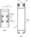
- a functional wall module 200a can have subcomponents that can combine and/or assemble into an entity without visible divides. Except as otherwise described herein, the functional wall module 200a and its components and elements can be similar to or the same as the functional wall module 200 ( Figures 2A-2C ) and its respective components and elements.
- the functional wall module 200a can comprise a single or unitary extrusion that incorporates a modular conduit 110a. As such, the functional wall module 200a can seamlessly and unnoticeably connect to existing modular wall segments, plain wall modules, and/or other structures.
- the functional wall module 200a includes vertical supports 210c, 210d (whether integrated with or secured to the modular conduit 110) having connecting elements 250, which can interface with the snap-in connector 180.
- One or more snap-in connectors 180 can secure various vertical supports 210 one to another.
- the installer can couple or connect various vertical supports 210, thereby forming desired sequences of the functional wall modules 200a, plain wall modules, and modular wall segments (as further described below in connection with Figures 4A, 4B ).
- vertical supports 210a, 210b can have similar or the same connecting elements 250, which can allow the installer to secure the functional wall module 200 ( Figures 2A , 2B ) to other wall modules and modular wall segments.
- the user can decouple the snap-in connectors 250 and can reposition the functional wall module 200a and/or the modular walls connected thereto, based on new requirements.
- uncoupling the snap-in connectors 250 from the vertical supports 210 can allow the installer to service or repair the functional wall module 200a as well as replace the functional wall module 200a and any of the wall modules or wall segments connected thereto. Accordingly, such modular coupling provided by the vertical supports 210 and connecting elements 250 can provide more flexibility for the installer as well as for the occupants of the building, which may reduce operating cost thereof.
- modular conduit 110a can have integrated or uninterrupted conduit walls.
- one or more panels can at least partially form or define the conduit walls, which can be visible to the occupants of the individual spaces.
- the conduit walls can incorporate various decorative elements and can provide aesthetically pleasing views to the occupants.
- the conduit walls can comprise decorative panels, such as thermoplastic panels that have aesthetically pleasing appearances.
- the integrated conduit walls incorporate one or more registers, located anywhere along the length of the modular conduit 110a.
- the conduit walls and/or panels also form outlets and/or inlets for the fluid to flow into and out of the individual space, respectively.
- the integrated conduit walls have perforations in desired locations, which permit the air to flow into or out of the individual space.
- the functional wall module 200a has integrated vertical supports 210c, 210d that, together with the modular conduit 110a, forms a single or unitary functional wall module 200a.
- the vertical supports 210c, 210d in addition to providing structural rigidity and support to the modular conduit 110a and/or to the functional wall module 200a, can have an aesthetically pleasing appearance (e.g., such as to compliment or blend in with adjacent wall modules).
- a portion of the vertical supports 210c, 210d that is visible to the occupants can have appealing aesthetic, which can match the conduit walls or panels of the functional wall module 200a.
- the conduit walls and the vertical supports 210c, 210d can share a surface that can appear to the occupants as a single or unitary surface.
- the modular conduit system and/or the functional wall module 200a can have panels that incorporate a channel therein, which can form a conduit within such panels.
- implementations of the present invention also include a modular conduit system that can have integrated panels 230. Additionally the modular conduit system can have a configuration that allows the installer to secure the panels thereto, as noted above.
- the panels of the functional wall module also can couple to the frame thereof in a manner that prevents or limits leakage of fluid near or through the connections therebetween.
- the panels once coupled to the vertical and/or horizontal supports of the functional wall module, the panels can form or define a modular conduit within such wall module.
- the fluid e.g., air
- the panels can incorporate opening or perforations (e.g., similar to the front plate 150 ( Figure 1A )), which can allow the fluid to enter or exit the functional wall module and flow into or out of the fluid distribution system, coupled to the functional wall module.
- the installer can integrate or couple the functional wall modules with other wall modules (e.g., functional or plain wall modules) and modular wall segments of existing or new partitions and modular walls.
- the functional wall modules, plain wall modules, modular wall segments, and similar structures can form individual spaces of various shapes, sizes, and use configurations. Such individual spaces include but are not limited to offices, kitchens, conference rooms, labs, and clean rooms.
- the functional wall modules can have a desired configuration and shape depending on a particular use and a particular individual space that the functional wall modules or the modular conduit system services.
- the functional wall modules can have a substantially flat, arcuate, wave-like, or other desired shapes, depending on the occupants' preferences.
- the builder or occupants of a building can use functional wall modules to conceal a permanent or temporary wall or partition.
- the builder can secure the functional wall modules as well as other modular wall segments or similar structures to an unfinished wall.
- Such functional wall modules and other structures can enhance overall aesthetic appeal of the occupants' environment.
- the builder can assemble multiple wall modules, include functional wall modules and plain wall modules into a modular wall system installation, which can provide flexibility for configuring and reconfiguring individual spaces within the building.
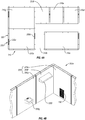
- Figures 4A, 4B illustrate exemplary implementations of modular wall installations 300, 300a.
- the modular wall installation 300 can include multiple wall modules that define individual spaces 310 (e.g., 310a, 310b, 310c, 310d, 310e, 310f, 310g) within a building.
- multiple plain wall modules 320 and/or functional wall modules 200 can selectively couple together in various arrangements to form the individual spaces 310.
- the modular wall installation 300 also can incorporate the functional wall modules 200a ( Figure 3 ) or any other functional wall modules in a similar manner.
- the individual spaces 310 can have any number of suitable shapes and sizes, which can vary from one implementation to another. Furthermore, as mentioned above, the individual spaces 310 have fluid supply or removal therein. More specifically, one or more functional wall modules 200 at least partially form the individual spaces 310 and, thus, supply fluid thereto and/or remove fluid therefrom. In one or more implementations, the functional wall module 200 can be sized and configured to allow the functional wall module 200 to connect to other functional wall modules and/or to plain wall modules 320.
- the individual space 310a can comprise functional wall modules 200c, 200d coupled to the respectively adjacent plain wall modules 320.
- the functional wall modules 200c, 200d together with the plain wall modules 320 form the general shape and size of the individual space 310a (e.g., the individual spaces 310a can have a substantially rectangular shape).
- the functional wall modules 200c, 200d supply one or more fluids to and/or remove one or more fluids from the individual space 310a.
- the same functional wall module 200 can both supply fluid to the individual spaces 310a and remove fluid from the individual space 310a.
- the functional wall module 200c can supply conditioned air into the individual space 310a as well as remove air from the individual space 310a, such as to cool, to heat, and/or to otherwise condition the air.
- a first functional wall module 200 (or a first set of functional wall modules 200) can supply the fluid into the individual space 310a
- a second functional wall module 200 (or a second set of functional wall modules 200) can remove the fluid from the individual space 310a.
- the functional wall module 200c can supply the conditioned air into the individual space 310a
- the functional wall module 200d can remove the air from the individual space 310a, and vice versa.
- a single functional wall module 200 can service multiple individual spaces 310.
- implementations of the present invention can include the functional wall module 200 that at least partially forms or defines two separate and/or adjacent individual spaces 310.
- the functional wall module 200d partially defines the individual space 310a and the adjacent individual space 310b.
- the functional wall module 200d may supply fluid into the individual space 310a and/or individual space 310b as well as remove fluid therefrom.
- the functional wall modules 200 can connect to existing fluid distribution systems within the building.
- the functional wall modules 200 can connect to an existing overhead fluid distribution system.
- the fluid distribution system conduit can connect to a central distribution center, such as a heating and/or air conditioning unit (or multiple units).
- the existing fluid distribution systems can provide a channel for fluid to flow into and/or out of the functional wall module 200.
- the builder can add new segments (e.g., overhead ducts) that connect to the existing fluid distribution system unit ("air handler"), which can provide heating, cooling, air conditioning, air filtration, etc. The builder or installer can then connect such new connector conduit to the functional wall module 200.
- the builder can add connector conduits, such as flexible ducts, to connect the functional wall module 200 to the existing fluid distribution system.
- the builder can add permanent ducts or connector conduits that can connect the functional wall module 200 to the (existing or new) fluid distribution center, such as an air handler at a desired location.
- a modular wall installation 300a can include multiple functional wall modules 200, such as functional wall modules 200e, 200f, 200g. It should be noted that the particular connections or arrangements of the functional wall modules 200 illustrated in Figure 4B are only exemplary, and, as noted above, the modular wall installation 300a has one ore more functional wall modules 200 and additionally any number of plain wall modules connected or positioned in various suitable arrangements, which can vary from one implementation to another.
- the functional wall module 200e includes the modular conduit system that has a register (concealed by the front plate 150), which can supply air into the individual space or remove air therefrom, as described above.
- the functional wall modules 200 also may have inlets and/or outlets that provide for connecting functional devices.
- functional wall module 200f can incorporate an outlet for connecting a functional device 330f, which can remove air or gases from the individual space, through the functional wall module 200f and, subsequently, into the fluid distribution system.
- the functional device 330f is a hood, which can remove air from a localize section of the individual space and force such removed air through the functional wall module 200f and into a fluid distribution system.
- the fluid distribution system can, thereafter, exhaust and/or filter the air removed by the hood.
- the modular wall installation 300a can include the functional wall module 200g, which can supply liquid to a functional device 330g (e.g., a sink).
- the functional wall module 200g also can remove liquid from the individual space at least partially defined by the functional wall module 200g.
- the functional wall module 200g can remove liquid from the functional device 330g.
- a horizontal support surface such as a floor can support the modular wall installation 300a as well as the functional wall modules 200.
- the building can have a suspended floor that can support the functional wall modules 200, plain wall modules, and modular wall segments.
- the suspended floor can house and/or conceal one or more fluid distribution systems (e.g., air distribution system, sewer system, plumbing, etc.).
- the functional wall modules 200 also can have any suitable height, which can vary from one implementation to the next.
- one or more of the functional wall modules 200 can have a partial height, such that a top of the functional wall module 200 does not reach the ceiling (or suspended ceiling) inside the building.
- the functional wall modules 200 can have full height, such that the tops of the functional wall modules 200 approximately abut the ceiling.
- the ceiling such as a suspended ceiling, also can house and conceal one or more fluid distribution systems.
- the functional wall module 200, the ceiling, and the floor conceal one or more fluid distribution systems as well as the ducts or other connector conduits that connect the functional wall modules 200 to such fluid distribution systems.
- modularity of the modular wall installation 300a can allow the installer to provide fluids at essentially any desired location or individual space within the building. Likewise, the modular wall installation 300a can remove fluids essentially from any location or individual space within the building. Moreover, when occupants' need change, the installer or occupants can readily and quickly rearrange the functional wall module 200 and plain wall modules to reconfigure the modular wall installation and/or the individual spaces as desired or preferred.
- Figures 1A-4B and the corresponding text provide a number of different components and mechanisms for creating modular conduit systems, functional wall modules, and modular wall installations.
- implementations of the present invention also includes a method of setting up modular wall installations according to claim 12.
- the method can be described in terms of flowcharts comprising acts and steps in a method for accomplishing a particular result.
- Figure 5 illustrates a flowchart of one exemplary method for setting up a modular wall installation. The acts of Figure 5 are described below with reference to the components and diagrams of Figures 1A through 4B .
- Figure 5 illustrates that, a method for setting up the modular wall installation 300, 300a includes an act 350 of securing the modular conduit system 100, 100a to or within the frame of the functional wall module 200, 200a.
- the installer prepares or assembles the frame of the functional wall module 200, 200a.
- the frame of the functional wall module 200, 200a comprises vertical supports 210 (e.g., left and right vertical supports 210a, 210b) and horizontal supports 220 (e.g., front and back horizontal supports 220a, 220b).
- the vertical supports 210 and the horizontal supports 220 are coupled together to form the frame of the functional wall module 200, 200a.
- the installer couples or secures the modular conduit system 100, 100a to the vertical and/or horizontal supports 210, 220.
- the installer secures vertical conduit supports 160 (e.g., left and right vertical conduit supports 160a, 160b) to the horizontal supports 220 of the frame.
- the vertical conduit supports 160 can have screw-in or snap-in connections with the horizontal supports 220.
- the vertical conduit supports 160 also can couple to the vertical supports 210.
- the method can include an act 360 of coupling the functional wall module 200, 200a to other wall modules to form the modular wall installation 300, 300a.
- the functional wall module 200, 200a can selectively couple to other functional wall modules, which also can provide fluid to and/or remove fluids from the individual spaces 310 (e.g., individual spaces 310a, 310b, 310c, 310d, 310e, 310f, 310g).
- the functional wall module 200, 200a can selectively couple to one or more plain wall modules.
- one or more functional wall modules 200, 200a as well as one or more plain wall modules can couple together to form the modular wall installation 300, 300a, which can provide various individual spaces 310.
- the installer can easily decouple the functional wall module 200, 200a from adjacent wall modules and/or wall segments. As such, the installer can reconfigure the individual spaces 310 when occupants' needs change. For instance, the installer can add or remove functional wall modules 200, 200a to/from the individual spaces 310. Additionally or alternatively, the installer can replace the one functional wall module 200, 200a with another (e.g., different) functional wall module 200, 200a. In any event, selective coupling of the functional wall modules 200, 200a with adjacent wall modules and modular wall segments can allow the occupants to modify the individual spaces 310 on demand and without demolishing or damaging existing structures.
- the vertical and/or horizontal supports 210, 220 can allow the manufacturer to couple one or more panels 230 to the frame of the functional wall module 200, 200a.
- the method also includes an act 370 of securing one or more panels 230 (e.g., front and back panels 230a, 230b) to the frame of the functional wall module 200, 200a.
- the panels 230 can couple to the front and/or back horizontal supports 220a, 220b.
- the panels 230 can snap to the horizontal supports 220a, 220b.
- the installer or occupants can selectively remove and/or reattach the panels 230 from/to the functional wall module 200, 200a. Consequently, the installer can conceal the modular conduit system 100, 100a behind one or more panels 230. Furthermore, by removing the one or more panels 230 from the frame of the functional wall module 200, 200a, the installer can gain access to and can perform work on the modular conduit system 100, 100a.
- the present disclosure is not limited to a particular sequence of acts described above.
- the acts 350, 360, and 370 can be performed in any number of sequences, which can vary from one implementation to another.
- the method can include the act 370 of securing one or more panels 230 to the frame of the functional wall module 200, 200a that occurs before the act 360 of coupling the functional wall module 200, 200a to other wall modules to form the modular wall installation 300, 300a.
- implementations of the above-described method need not necessarily include every single act described herein.
- the scope of the invention is limited by the appended claims.
- the present invention may be embodied in other specific forms without departing from its essential characteristics.
- the described embodiments are to be considered in all respects only as illustrative and not restrictive. The scope of the invention is, therefore, defined by the appended claims.
Landscapes
- Engineering & Computer Science (AREA)
- Architecture (AREA)
- Civil Engineering (AREA)
- Physics & Mathematics (AREA)
- Electromagnetism (AREA)
- Structural Engineering (AREA)
- Chemical & Material Sciences (AREA)
- Combustion & Propulsion (AREA)
- Mechanical Engineering (AREA)
- General Engineering & Computer Science (AREA)
- Duct Arrangements (AREA)
Claims (15)
- Funktionales Wandmodul (200), um zumindest teilweise einen einzelnen Raum zu bilden und um Fluide in dem einzelnen Raum bereitzustellen oder Fluide daraus zu entfernen, wobei das funktionale Wandmodul (200) einen oder mehrere vertikale Träger (170, 210) und einen oder mehrere horizontale Träger (220) umfasst, welche an mindestens einem der einen oder mehreren vertikalen Träger (170, 210) befestigt sind, wobei das funktionale Wandmodul (200) ferner aufweist:
ein modulares Leitungssystems (100), welches an mindestens einem der einen oder mehreren vertikalen Träger oder mindestens einem der einen oder mehreren horizontalen Träger (220) gekoppelt ist, wobei das modulare Leitungssystem (100) aufweist:eine modulare Leitung (110), welche dafür bemessen und ausgelegt ist, um ein oder mehrere Fluide in den einzelnen Raum zuzuführen und Fluide aus dem einzelnen Raum abzuführen; undeinen oder mehrere vertikale Leitungsträger (160), welche an die modulare Leitung (110) gekoppelt sind und diese zumindest teilweise tragen, wobei der eine oder die mehreren vertikalen Leitungsträger (160) ferner an mindestens einen von dem einen oder den mehreren vertikalen Trägern (170, 210) und dem einen oder den mehreren horizontalen Trägern (220) gekoppelt ist;dadurch gekennzeichnet, dass die modulare Leitung (110) mindestens ein Register (140) umfasst, welches innerhalb der modularen Leitung (110) vertikal repositionierbar ist, was es dem Register (140) ermöglicht, von einem Benutzer des einzelnen Raums von einer ersten vertikalen Position zu einer zweiten verschiedenen vertikalen Position in dem modularen Leitungssystem (100) bewegt zu werden, wobei das Register (140) eine oder mehrere Dichtungen enthält, welche den Fluidstrom durch das Register (140) kanalisieren, wobei das Register (140) eine gelochte Verteilerplatte als eine Frontplatte (150) aufweist, welche bündig mit dem modularen Leitungssystem ausgerichtet ist, so dass das Register (140) und die Frontplatte (150) es dem Fluid ermöglichen, in die und/oder aus der modularen Leitung (110) zu strömen. - Funktionales Wandmodul (200) nach Anspruch 1, ferner aufweisend eine oder mehrere Tafeln (230), welche an mindestens einem von dem einen oder den mehreren vertikalen Träger (170, 210) oder an mindestens einem von dem einen oder den mehreren horizontalen Träger (220) abnehmbar befestigt sind.
- Funktionales Wandmodul (200) nach Anspruch 2, wobei die eine oder mehreren Tafeln (230) eine Schnappverbindung mit dem mindestens einen von dem einen oder den mehreren vertikalen Trägern (170, 210) und dem einen oder den mehreren horizontalen Trägern (220) aufweist,
oder wobei die modulare Leitung (110) eine ähnliche Querschnittsform wie eine Querschnittsform des funktionalen Wandmoduls (200) aufweist, wie sie durch die eine oder mehreren Tafeln (230) davon definiert wird. - Funktionales Wandmodul (200) nach Anspruch 1, wobei das modulare Leitungssystem (100) ferner ein Register (140) aufweist, welches wirksam damit verknüpft ist,
insbesondere wobei das modulare Leitungssystem (100) ferner eine an der modularen Leitung (110) befestigte Frontplatte (150) aufweist, wobei die Frontplatte (150) dafür bemessen und ausgelegt ist, um das Register (140) zu verdecken, und wobei die Frontplatte (150) eine oder mehrere Öffnungen aufweist, um Luft zu ermöglichen, aus der oder in die modulare Leitung (110) dort hindurch zu gelangen. - Funktionales Wandmodul (200) nach Anspruch 1, wobei der eine oder die mehreren Leitungsträger (160) ferner an mindestens einen von dem einen oder den mehreren vertikalen Trägern (170, 210) und einen oder mehreren horizontalen Trägern (220) gekoppelt ist.
- Funktionales Wandmodul (200) nach Anspruch 1, wobei das modulare Leitungssystem (100) ferner einen damit gekoppelten oder darin integrierten Einlass (120) aufweist, wobei der Einlass (120) dafür bemessen und ausgelegt ist, um Fluid aus einem Fluidverteilungssystem aufzunehmen oder zu diesem zu schicken.
- Modulare Wandinstallation zum Bilden eines einzelnen Raums, welcher Fluidzufuhr dorthin und/oder Fluidabfuhr von dort aufweist, wobei die Wandinstallation aufweist:ein oder mehrere Wandmodule, welche wahlweise und abnehmbar miteinander gekoppelt sind, wobei das eine oder die mehreren Wandmodule den einzelnen Raum bilden; wobei das eine oder die mehreren Wandmodule aufweisen: mindestens ein einfaches Wandmodul mit einem ersten Rahmen und einer oder mehreren, an dem ersten Rahmen befestigten Tafeln (230);mindestens ein funktionales Wandmodul (200) gemäß einem der Ansprüche 1 bis 6, welches einen Rahmen und ein modulares Leitungssystem (100) aufweist, welches an oder innerhalb des Rahmens des funktionalen Wandmoduls (200) befestigt ist.
- Modulare Wandinstallation nach Anspruch 7, ferner aufweisend ein Fluidverteilungssystem und eine oder mehrere Verbindungsleitungen, welche das funktionale Wandmodul (200) mit dem Fluidverteilungssystem verbinden.
- Modulare Wandinstallation nach Anspruch 8, wobei das modulare Leitungssystem (100) eine modulare Leitung (110) mit einem Einlass (120) und einem Auslass aufweist, wobei der Einlass (120) mit dem Fluidverteilungssystem verbunden ist, insbesondere ferner aufweisend eine oder mehrere funktionale Vorrichtungen (330f, 330g), welche an dem Auslass der modularen Leitung (110) angeschlossen sind.
- Modulare Wandinstallation nach Anspruch 7, wobei das mindestens eine funktionale Wandmodul (200) ferner eine oder mehrere Tafeln (230) umfasst, welche am Rahmen davon befestigt sind,
insbesondere wobei:der erste Rahmen des mindestens einen einfachen Wandmoduls einen oder mehrere vertikale Träger (170, 210) mit Verbindungselementen aufweist;der Rahmen des mindestens einen funktionalen Wandmoduls einen oder mehrere vertikale Träger (170, 210) mit Verbindungselementen aufweist; undmindestens ein Schnappverbinder die vertikalen Träger (170, 210) des mindestens einen einfachen Wandmoduls mit den vertikalen Trägern (170, 210) des mindestens einen funktionalen Wandmoduls (200) abnehmbar befestigt. - Modulare Wandinstallation nach Anspruch 7, wobei das mindestens eine funktionale Wandmodul (200) Fluid in mindestens zwei einzelne Räume befördert oder Fluid aus mindestens zwei einzelnen Räumen entfernt.
- Verfahren zum Aufstellen einer modularen Wandinstallation, welche zur gezielten Konfiguration und Rekonfiguration geeignet ist und ferner zum Befördern von Fluid sowie Entfernen von Fluid aus einem einzelnen Raum geeignet ist, wobei das Verfahren aufweist:Zusammenbauen eines Rahmens eines ersten funktionalen Wandmoduls (200) nach einem der Ansprüche 1 bis 6;Befestigen eines modularen Leitungssystems (100) an oder innerhalb des Rahmens des ersten funktionalen Wandmoduls;Befestigen einer oder mehrerer Tafeln (230) an dem Rahmen des ersten funktionalen Wandmoduls; undwahlweise Koppeln des ersten funktionalen Wandmoduls an ein oder mehrere Wandmodule, wodurch der einzelne Raum gebildet wird, wobei das eine oder die mehreren Wandmodule ein oder mehrere eines zweiten funktionalen Wandmoduls (200) nach einem der Ansprüche 1 bis 6 aufweist und zusätzlich das eine oder die mehreren Wandmodule ferner ein oder mehrere eines einfachen Wandmoduls aufweist;dadurch gekennzeichnet, dass das modulare Leitungssystem (100) eine modulare Leitung (110) aufweist, welche mindestens ein Register (140) umfasst, welches innerhalb der modularen Leitung (110) vertikal repositionierbar ist, was es dem Register (140) ermöglicht, von einem Benutzer des einzelnen Raums von einer ersten vertikalen Position zu einer zweiten, verschiedenen vertikalen Position in dem modularen Leitungssystem (100) bewegt zu werden, wobei das Register (140) eine oder mehrere Dichtungen enthält, welche den Fluidstrom durch das Register (140) kanalisieren,wobei das Register (140) eine gelochte Verteilerplatte als eine Frontplatte (150) aufweist, welche bündig mit dem modularen Leitungssystem ausgerichtet ist, so dass das Register (140) und die Frontplatte (150) es dem Fluid ermöglichen, in die und/oder aus der modularen Leitung (110) zu strömen.
- Verfahren nach Anspruch 12, wobei wahlweise Koppeln des ersten funktionalen Wandmoduls an ein oder mehrere Wandmodule Befestigen eines vertikalen Trägers des ersten funktionalen Wandmoduls an einem vertikalen Träger des einen oder der mehreren Wandmodule mit einem Schnappverbinder aufweist.
- Verfahren nach Anspruch 12, wobei Befestigen des modularen Leitungssystems (100) an oder innerhalb des Rahmens des ersten funktionalen Wandmoduls Befestigen von mindestens einem vertikalen Leitungsträger des modularen Leitungssystems (100) an dem Rahmen des Rahmens des ersten funktionalen Wandmoduls aufweist,
insbesondere wobei:
der Rahmen des ersten funktionalen Wandmoduls ein oder mehrere vertikale Trägerelemente und ein oder mehrere horizontale Trägerelemente aufweist, welche an die vertikalen Trägerelemente gekoppelt sind, und Befestigen von mindestens einem vertikalen Leitungsträger des modularen Leitungssystems (100) an dem Rahmen des ersten funktionalen Wandmoduls Befestigen des mindestens einen vertikalen Leitungsträgers an mindestens einem von dem einen oder den mehreren horizontalen Trägern (220) aufweist. - Verfahren nach Anspruch 12, ferner aufweisend Entkoppeln und Entfernen des ersten funktionalen Wandmoduls von dem einen oder den mehreren Wandmodulen und wahlweise Koppeln eines dritten funktionalen Wandmoduls an das eine oder die mehreren Wandmodule, wobei das dritte funktionale Wandmodul von dem ersten funktionalen Wandmodul verschieden ist.
Applications Claiming Priority (2)
| Application Number | Priority Date | Filing Date | Title |
|---|---|---|---|
| US201261605061P | 2012-02-29 | 2012-02-29 | |
| PCT/US2013/028404 WO2013130871A1 (en) | 2012-02-29 | 2013-02-28 | Modular in-wall functional conduits |
Publications (3)
| Publication Number | Publication Date |
|---|---|
| EP2820198A1 EP2820198A1 (de) | 2015-01-07 |
| EP2820198A4 EP2820198A4 (de) | 2015-10-21 |
| EP2820198B1 true EP2820198B1 (de) | 2018-05-30 |
Family
ID=49083302
Family Applications (1)
| Application Number | Title | Priority Date | Filing Date |
|---|---|---|---|
| EP13754328.6A Not-in-force EP2820198B1 (de) | 2012-02-29 | 2013-02-28 | Modulare wandinterne funktionsleitungen |
Country Status (3)
| Country | Link |
|---|---|
| US (1) | US9719251B2 (de) |
| EP (1) | EP2820198B1 (de) |
| WO (1) | WO2013130871A1 (de) |
Families Citing this family (27)
| Publication number | Priority date | Publication date | Assignee | Title |
|---|---|---|---|---|
| CA2516083C (en) | 2004-08-17 | 2013-03-12 | Dirtt Environmental Solutions Ltd. | Integrated reconfigurable wall system |
| USRE47132E1 (en) | 2004-08-17 | 2018-11-20 | Dirtt Environmental Solutions, Ltd | Integrated reconfigurable wall system |
| CA2796997C (en) | 2011-06-11 | 2016-05-10 | Dirtt Environmental Solutions, Ltd. | Modular wall nesting system |
| US9084489B2 (en) | 2011-12-28 | 2015-07-21 | Dirtt Environmental Solutions, Ltd. | Modular walls incorporating recessed, extendable furniture |
| US11085184B2 (en) | 2014-02-20 | 2021-08-10 | Dirtt Environmental Solutions Ltd. | Interface for mounting interchangable components |
| US10058170B2 (en) | 2016-02-10 | 2018-08-28 | Dirtt Environmental Solutions, Ltd | Modular walls with embedded furniture and opposing feature |
| US10844609B2 (en) * | 2016-04-22 | 2020-11-24 | Jimmy Keith Yeary, JR. | Building rail system |
| US11240922B2 (en) | 2016-06-10 | 2022-02-01 | Dirtt Environmental Solutions Ltd. | Wall system with electronic device mounting assembly |
| US11093087B2 (en) | 2016-06-10 | 2021-08-17 | Dirtt Environmental Solutions Ltd. | Glass substrates with touchscreen technology |
| EP3482255A4 (de) | 2016-07-08 | 2020-03-11 | DIRTT Environmental Solutions, Ltd. | Intelligentes glas mit niedriger spannung |
| IT201800005734A1 (it) * | 2018-05-25 | 2019-11-25 | Struttura di canale per il convogliamento di aria. | |
| US11085182B2 (en) * | 2019-01-08 | 2021-08-10 | Versare Solutions, Llc | Modular wall panels and system |
| US11174632B2 (en) * | 2019-01-08 | 2021-11-16 | Versare Solutions, Llc | Modular wall panels and system |
| CN110231882B (zh) * | 2019-04-12 | 2024-11-29 | 深圳全景空间工业有限公司 | 一种智慧墙及智慧建筑 |
| US11719462B2 (en) * | 2019-08-12 | 2023-08-08 | ACSM, Inc. | Duct support assembly and method of using a duct support |
| US12467255B2 (en) * | 2019-08-30 | 2025-11-11 | Sekisui House, Ltd. | Partitioning storage rack and building |
| NL2023734B1 (en) * | 2019-08-30 | 2021-05-11 | Dutch Innovation In Air Treat B V | A gas flow system |
| JP7495051B2 (ja) * | 2020-01-07 | 2024-06-04 | 合同会社リーサステクノ | 壁埋め込み型空気循環パネル |
| US11680403B2 (en) * | 2020-09-21 | 2023-06-20 | Amp Ip Llc | Multi-purpose structural panels and systems for assembling structures |
| US11864296B2 (en) | 2020-11-04 | 2024-01-02 | Midea Group Co., Ltd. | Mounting arrangement for over-the-range cooking appliance |
| DE102020133645A1 (de) | 2020-12-16 | 2022-06-23 | Drägerwerk AG & Co. KGaA | Konfigurierbare Anordnung zur medizinischen Versorgung eines Patienten |
| KR102345056B1 (ko) * | 2021-05-13 | 2021-12-29 | 노원훈 | 솔레노이드를 이용한 모듈식 벽체 조립체 |
| US12064033B2 (en) | 2021-06-21 | 2024-08-20 | Midea Group Co., Ltd. | Mounting bracket assembly for appliance |
| US12366365B2 (en) | 2021-06-21 | 2025-07-22 | Midea Group Co., Ltd. | Mounting bracket for over-the-range cooking appliance |
| US12121147B2 (en) | 2021-06-21 | 2024-10-22 | Midea Group Co., Ltd. | Mounting bracket for over-the-range cooking appliance with drill guide |
| GB202109234D0 (en) * | 2021-06-25 | 2021-08-11 | Eekowall Ltd | Wall panel |
| US20230203805A1 (en) * | 2021-12-27 | 2023-06-29 | Calum W. Smeaton | Apparatus with Interchangeable Panels for Varying Acoustic and Esthetic Treatments or Effects |
Citations (1)
| Publication number | Priority date | Publication date | Assignee | Title |
|---|---|---|---|---|
| WO1982000190A1 (en) * | 1980-07-09 | 1982-01-21 | Carlson A | Air recycling device |
Family Cites Families (31)
| Publication number | Priority date | Publication date | Assignee | Title |
|---|---|---|---|---|
| US1863981A (en) * | 1930-06-17 | 1932-06-21 | James S Groves | Concrete building construction |
| US2182422A (en) * | 1933-09-30 | 1939-12-05 | William C Bond | Library bookstack |
| US2781657A (en) * | 1951-06-29 | 1957-02-19 | Structural Clay Products Res F | Pre-stressed clay tile partition panels |
| US2849942A (en) * | 1954-02-24 | 1958-09-02 | Robertson Co H H | Multi-storied building and air conditioning structure |
| US2822898A (en) | 1955-01-07 | 1958-02-11 | Archer W Richards | Joint and connector used therein |
| US3694973A (en) * | 1970-08-14 | 1972-10-03 | Midweco Enterprise Inc | Utility module for apartment-type dwellings |
| US3771273A (en) * | 1971-03-04 | 1973-11-13 | J Brodie | Prefabricated building |
| US4007574A (en) * | 1975-09-22 | 1977-02-15 | Riddell C Randolph | Structural member and system |
| US4353411A (en) * | 1980-02-04 | 1982-10-12 | Harter James L | Architectural support and service assembly |
| US4457116A (en) * | 1980-06-12 | 1984-07-03 | Kump Ernest J | Space module |
| US4365590A (en) * | 1981-07-20 | 1982-12-28 | Lab Products, Inc. | Ventilated animal cage rack |
| LU85045A1 (de) | 1983-10-12 | 1984-03-22 | ||
| US4905428A (en) * | 1988-11-16 | 1990-03-06 | Sykes Christopher C | Partition structures and frame elements therefor |
| US5175969A (en) * | 1991-06-06 | 1993-01-05 | Steelcase Inc. | Partition panel |
| JPH0528782A (ja) | 1991-07-25 | 1993-02-05 | Toshiba Corp | 不揮発性半導体記憶装置 |
| JP3140154B2 (ja) * | 1992-04-03 | 2001-03-05 | 松下精工株式会社 | 喫煙用パーティション |
| JP2629605B2 (ja) | 1994-07-27 | 1997-07-09 | コクヨ株式会社 | 空調パネル |
| US5761864A (en) * | 1994-08-31 | 1998-06-09 | Nonoshita; Tadamichi | Thermally insulated building and a building panel therefor |
| JPH0941556A (ja) | 1995-07-31 | 1997-02-10 | Oshikiri:Kk | 空調用側壁中空パネルおよびそれを使用した壁構造物 |
| US5953871A (en) * | 1998-02-03 | 1999-09-21 | Design Board Industries Inc | Modular wall panel |
| US7174678B2 (en) | 1999-04-22 | 2007-02-13 | Hill-Rom Services, Inc. | Modular patient room |
| US6574932B2 (en) * | 2001-03-09 | 2003-06-10 | Steel Block, Inc. | Embeddable air duct block and method |
| NL1024937C2 (nl) | 2003-12-03 | 2005-06-06 | Unispace A G | Geluidswerende scheidingswand en werkwijze voor het monteren van een dergelijke scheidingswand. |
| CA2516083C (en) * | 2004-08-17 | 2013-03-12 | Dirtt Environmental Solutions Ltd. | Integrated reconfigurable wall system |
| US20070084139A1 (en) * | 2005-10-17 | 2007-04-19 | Stender Mark L | Exterior wall assembly |
| US20070137128A1 (en) * | 2005-12-02 | 2007-06-21 | Nicolas Viau | Modular stone panel |
| US7642471B2 (en) * | 2007-10-10 | 2010-01-05 | Milan Whitaker | Fly-by-box |
| CA2648822C (en) * | 2008-10-20 | 2014-12-09 | Arthur George Paetkau | Prefabricated building panels and structures, building, methods and systems relating to same |
| CA2740168C (en) * | 2010-05-14 | 2012-08-21 | Feature Walters | Modular building panel and duct system |
| KR200460703Y1 (ko) | 2010-06-22 | 2012-06-13 | 주식회사 문인 | 크린 룸 내장판넬 |
| US8490352B2 (en) * | 2011-01-17 | 2013-07-23 | Precise Forms, Inc. | Concrete sandwich wall insert |
-
2013
- 2013-02-28 EP EP13754328.6A patent/EP2820198B1/de not_active Not-in-force
- 2013-02-28 WO PCT/US2013/028404 patent/WO2013130871A1/en not_active Ceased
- 2013-02-28 US US14/003,287 patent/US9719251B2/en active Active
Patent Citations (1)
| Publication number | Priority date | Publication date | Assignee | Title |
|---|---|---|---|---|
| WO1982000190A1 (en) * | 1980-07-09 | 1982-01-21 | Carlson A | Air recycling device |
Also Published As
| Publication number | Publication date |
|---|---|
| WO2013130871A1 (en) | 2013-09-06 |
| EP2820198A4 (de) | 2015-10-21 |
| US20150143763A1 (en) | 2015-05-28 |
| EP2820198A1 (de) | 2015-01-07 |
| US9719251B2 (en) | 2017-08-01 |
Similar Documents
| Publication | Publication Date | Title |
|---|---|---|
| EP2820198B1 (de) | Modulare wandinterne funktionsleitungen | |
| AU2017315205A1 (en) | Attachment profile member allowing the passage of air and ceiling assembly comprising such a profile member | |
| US5953871A (en) | Modular wall panel | |
| CN102771202A (zh) | 数据中心空气路由系统 | |
| US20030226323A1 (en) | Structure having preinstalled utilities and amenities | |
| CA2817255C (en) | Modular in-wall functional conduits | |
| JP7387255B2 (ja) | 全館空調システム | |
| US20020094773A1 (en) | Cornice duct system | |
| CN111868391A (zh) | 风扇和包括该风扇的空调单元 | |
| JP3759777B2 (ja) | 天井空調装置 | |
| MX2007005109A (es) | Sistema modular de division de espacio. | |
| US20050090195A1 (en) | Cornice duct system | |
| US5257738A (en) | Supply air terminal device | |
| EP1334315A1 (de) | System und verfahren zur klimatisierung eines raums, decke für diesen zweck und verfahren zur installierung eines solchen systems | |
| KR101517167B1 (ko) | 분리형 변풍량 리니어 디퓨저 및 분리형 변풍량 리니어 디퓨저 시공방법 | |
| US20240318859A1 (en) | Integrated ceiling and hvac duct system | |
| JP4355509B2 (ja) | 床下暖房付キャビネット | |
| US20030140646A1 (en) | Cornice duct system | |
| CN223939548U (zh) | 空调 | |
| KR100743300B1 (ko) | 공기 조화 시스템 | |
| JP7606795B1 (ja) | 空調用部品セット、空調用部品、空調システム及び建築物 | |
| KR102934314B1 (ko) | 실내 공기 정화 장치 | |
| US12416415B2 (en) | Hydronic assembly for providing heating, cooling, and ventilation | |
| EP2014993B1 (de) | Luft- und Thermopaneelleiste | |
| JP2000248684A (ja) | 天井材連結具および天井構造 |
Legal Events
| Date | Code | Title | Description |
|---|---|---|---|
| PUAI | Public reference made under article 153(3) epc to a published international application that has entered the european phase |
Free format text: ORIGINAL CODE: 0009012 |
|
| 17P | Request for examination filed |
Effective date: 20140926 |
|
| AK | Designated contracting states |
Kind code of ref document: A1 Designated state(s): AL AT BE BG CH CY CZ DE DK EE ES FI FR GB GR HR HU IE IS IT LI LT LU LV MC MK MT NL NO PL PT RO RS SE SI SK SM TR |
|
| AX | Request for extension of the european patent |
Extension state: BA ME |
|
| RAP1 | Party data changed (applicant data changed or rights of an application transferred) |
Owner name: DIRTT ENVIRONMENTAL SOLUTIONS, LTD. Owner name: GOSLING, GEOFF |
|
| DAX | Request for extension of the european patent (deleted) | ||
| RA4 | Supplementary search report drawn up and despatched (corrected) |
Effective date: 20150921 |
|
| RIC1 | Information provided on ipc code assigned before grant |
Ipc: E04C 3/04 20060101ALN20150915BHEP Ipc: F24F 13/02 20060101ALI20150915BHEP Ipc: E04B 2/74 20060101ALI20150915BHEP Ipc: E04B 2/72 20060101AFI20150915BHEP Ipc: E04B 1/343 20060101ALI20150915BHEP |
|
| 17Q | First examination report despatched |
Effective date: 20160803 |
|
| STAA | Information on the status of an ep patent application or granted ep patent |
Free format text: STATUS: EXAMINATION IS IN PROGRESS |
|
| GRAP | Despatch of communication of intention to grant a patent |
Free format text: ORIGINAL CODE: EPIDOSNIGR1 |
|
| STAA | Information on the status of an ep patent application or granted ep patent |
Free format text: STATUS: GRANT OF PATENT IS INTENDED |
|
| RIC1 | Information provided on ipc code assigned before grant |
Ipc: E04B 1/343 20060101ALI20171124BHEP Ipc: E04C 3/04 20060101ALN20171124BHEP Ipc: F24F 13/02 20060101ALI20171124BHEP Ipc: E04B 2/74 20060101ALI20171124BHEP Ipc: E04B 2/72 20060101AFI20171124BHEP |
|
| INTG | Intention to grant announced |
Effective date: 20171214 |
|
| RIC1 | Information provided on ipc code assigned before grant |
Ipc: E04C 3/04 20060101ALN20171204BHEP Ipc: E04B 2/72 20060101AFI20171204BHEP Ipc: E04B 2/74 20060101ALI20171204BHEP Ipc: F24F 13/02 20060101ALI20171204BHEP Ipc: E04B 1/343 20060101ALI20171204BHEP |
|
| GRAS | Grant fee paid |
Free format text: ORIGINAL CODE: EPIDOSNIGR3 |
|
| GRAA | (expected) grant |
Free format text: ORIGINAL CODE: 0009210 |
|
| STAA | Information on the status of an ep patent application or granted ep patent |
Free format text: STATUS: THE PATENT HAS BEEN GRANTED |
|
| AK | Designated contracting states |
Kind code of ref document: B1 Designated state(s): AL AT BE BG CH CY CZ DE DK EE ES FI FR GB GR HR HU IE IS IT LI LT LU LV MC MK MT NL NO PL PT RO RS SE SI SK SM TR |
|
| REG | Reference to a national code |
Ref country code: GB Ref legal event code: FG4D |
|
| REG | Reference to a national code |
Ref country code: CH Ref legal event code: EP |
|
| REG | Reference to a national code |
Ref country code: AT Ref legal event code: REF Ref document number: 1003746 Country of ref document: AT Kind code of ref document: T Effective date: 20180615 |
|
| REG | Reference to a national code |
Ref country code: IE Ref legal event code: FG4D |
|
| REG | Reference to a national code |
Ref country code: DE Ref legal event code: R096 Ref document number: 602013038187 Country of ref document: DE |
|
| REG | Reference to a national code |
Ref country code: NL Ref legal event code: MP Effective date: 20180530 |
|
| REG | Reference to a national code |
Ref country code: LT Ref legal event code: MG4D |
|
| PG25 | Lapsed in a contracting state [announced via postgrant information from national office to epo] |
Ref country code: BG Free format text: LAPSE BECAUSE OF FAILURE TO SUBMIT A TRANSLATION OF THE DESCRIPTION OR TO PAY THE FEE WITHIN THE PRESCRIBED TIME-LIMIT Effective date: 20180830 Ref country code: FI Free format text: LAPSE BECAUSE OF FAILURE TO SUBMIT A TRANSLATION OF THE DESCRIPTION OR TO PAY THE FEE WITHIN THE PRESCRIBED TIME-LIMIT Effective date: 20180530 Ref country code: CY Free format text: LAPSE BECAUSE OF FAILURE TO SUBMIT A TRANSLATION OF THE DESCRIPTION OR TO PAY THE FEE WITHIN THE PRESCRIBED TIME-LIMIT Effective date: 20180530 Ref country code: SE Free format text: LAPSE BECAUSE OF FAILURE TO SUBMIT A TRANSLATION OF THE DESCRIPTION OR TO PAY THE FEE WITHIN THE PRESCRIBED TIME-LIMIT Effective date: 20180530 Ref country code: LT Free format text: LAPSE BECAUSE OF FAILURE TO SUBMIT A TRANSLATION OF THE DESCRIPTION OR TO PAY THE FEE WITHIN THE PRESCRIBED TIME-LIMIT Effective date: 20180530 Ref country code: ES Free format text: LAPSE BECAUSE OF FAILURE TO SUBMIT A TRANSLATION OF THE DESCRIPTION OR TO PAY THE FEE WITHIN THE PRESCRIBED TIME-LIMIT Effective date: 20180530 Ref country code: NO Free format text: LAPSE BECAUSE OF FAILURE TO SUBMIT A TRANSLATION OF THE DESCRIPTION OR TO PAY THE FEE WITHIN THE PRESCRIBED TIME-LIMIT Effective date: 20180830 |
|
| PG25 | Lapsed in a contracting state [announced via postgrant information from national office to epo] |
Ref country code: HR Free format text: LAPSE BECAUSE OF FAILURE TO SUBMIT A TRANSLATION OF THE DESCRIPTION OR TO PAY THE FEE WITHIN THE PRESCRIBED TIME-LIMIT Effective date: 20180530 Ref country code: RS Free format text: LAPSE BECAUSE OF FAILURE TO SUBMIT A TRANSLATION OF THE DESCRIPTION OR TO PAY THE FEE WITHIN THE PRESCRIBED TIME-LIMIT Effective date: 20180530 Ref country code: GR Free format text: LAPSE BECAUSE OF FAILURE TO SUBMIT A TRANSLATION OF THE DESCRIPTION OR TO PAY THE FEE WITHIN THE PRESCRIBED TIME-LIMIT Effective date: 20180831 Ref country code: LV Free format text: LAPSE BECAUSE OF FAILURE TO SUBMIT A TRANSLATION OF THE DESCRIPTION OR TO PAY THE FEE WITHIN THE PRESCRIBED TIME-LIMIT Effective date: 20180530 |
|
| REG | Reference to a national code |
Ref country code: AT Ref legal event code: MK05 Ref document number: 1003746 Country of ref document: AT Kind code of ref document: T Effective date: 20180530 |
|
| PG25 | Lapsed in a contracting state [announced via postgrant information from national office to epo] |
Ref country code: NL Free format text: LAPSE BECAUSE OF FAILURE TO SUBMIT A TRANSLATION OF THE DESCRIPTION OR TO PAY THE FEE WITHIN THE PRESCRIBED TIME-LIMIT Effective date: 20180530 |
|
| PG25 | Lapsed in a contracting state [announced via postgrant information from national office to epo] |
Ref country code: SK Free format text: LAPSE BECAUSE OF FAILURE TO SUBMIT A TRANSLATION OF THE DESCRIPTION OR TO PAY THE FEE WITHIN THE PRESCRIBED TIME-LIMIT Effective date: 20180530 Ref country code: RO Free format text: LAPSE BECAUSE OF FAILURE TO SUBMIT A TRANSLATION OF THE DESCRIPTION OR TO PAY THE FEE WITHIN THE PRESCRIBED TIME-LIMIT Effective date: 20180530 Ref country code: CZ Free format text: LAPSE BECAUSE OF FAILURE TO SUBMIT A TRANSLATION OF THE DESCRIPTION OR TO PAY THE FEE WITHIN THE PRESCRIBED TIME-LIMIT Effective date: 20180530 Ref country code: PL Free format text: LAPSE BECAUSE OF FAILURE TO SUBMIT A TRANSLATION OF THE DESCRIPTION OR TO PAY THE FEE WITHIN THE PRESCRIBED TIME-LIMIT Effective date: 20180530 Ref country code: DK Free format text: LAPSE BECAUSE OF FAILURE TO SUBMIT A TRANSLATION OF THE DESCRIPTION OR TO PAY THE FEE WITHIN THE PRESCRIBED TIME-LIMIT Effective date: 20180530 Ref country code: AT Free format text: LAPSE BECAUSE OF FAILURE TO SUBMIT A TRANSLATION OF THE DESCRIPTION OR TO PAY THE FEE WITHIN THE PRESCRIBED TIME-LIMIT Effective date: 20180530 Ref country code: EE Free format text: LAPSE BECAUSE OF FAILURE TO SUBMIT A TRANSLATION OF THE DESCRIPTION OR TO PAY THE FEE WITHIN THE PRESCRIBED TIME-LIMIT Effective date: 20180530 |
|
| PG25 | Lapsed in a contracting state [announced via postgrant information from national office to epo] |
Ref country code: SM Free format text: LAPSE BECAUSE OF FAILURE TO SUBMIT A TRANSLATION OF THE DESCRIPTION OR TO PAY THE FEE WITHIN THE PRESCRIBED TIME-LIMIT Effective date: 20180530 Ref country code: IT Free format text: LAPSE BECAUSE OF FAILURE TO SUBMIT A TRANSLATION OF THE DESCRIPTION OR TO PAY THE FEE WITHIN THE PRESCRIBED TIME-LIMIT Effective date: 20180530 |
|
| REG | Reference to a national code |
Ref country code: DE Ref legal event code: R097 Ref document number: 602013038187 Country of ref document: DE |
|
| PLBE | No opposition filed within time limit |
Free format text: ORIGINAL CODE: 0009261 |
|
| STAA | Information on the status of an ep patent application or granted ep patent |
Free format text: STATUS: NO OPPOSITION FILED WITHIN TIME LIMIT |
|
| 26N | No opposition filed |
Effective date: 20190301 |
|
| PG25 | Lapsed in a contracting state [announced via postgrant information from national office to epo] |
Ref country code: SI Free format text: LAPSE BECAUSE OF FAILURE TO SUBMIT A TRANSLATION OF THE DESCRIPTION OR TO PAY THE FEE WITHIN THE PRESCRIBED TIME-LIMIT Effective date: 20180530 |
|
| REG | Reference to a national code |
Ref country code: CH Ref legal event code: PL |
|
| PG25 | Lapsed in a contracting state [announced via postgrant information from national office to epo] |
Ref country code: MC Free format text: LAPSE BECAUSE OF FAILURE TO SUBMIT A TRANSLATION OF THE DESCRIPTION OR TO PAY THE FEE WITHIN THE PRESCRIBED TIME-LIMIT Effective date: 20180530 Ref country code: LU Free format text: LAPSE BECAUSE OF NON-PAYMENT OF DUE FEES Effective date: 20190228 |
|
| REG | Reference to a national code |
Ref country code: BE Ref legal event code: MM Effective date: 20190228 |
|
| REG | Reference to a national code |
Ref country code: IE Ref legal event code: MM4A |
|
| PG25 | Lapsed in a contracting state [announced via postgrant information from national office to epo] |
Ref country code: AL Free format text: LAPSE BECAUSE OF FAILURE TO SUBMIT A TRANSLATION OF THE DESCRIPTION OR TO PAY THE FEE WITHIN THE PRESCRIBED TIME-LIMIT Effective date: 20180530 |
|
| PG25 | Lapsed in a contracting state [announced via postgrant information from national office to epo] |
Ref country code: CH Free format text: LAPSE BECAUSE OF NON-PAYMENT OF DUE FEES Effective date: 20190228 Ref country code: LI Free format text: LAPSE BECAUSE OF NON-PAYMENT OF DUE FEES Effective date: 20190228 |
|
| PG25 | Lapsed in a contracting state [announced via postgrant information from national office to epo] |
Ref country code: IE Free format text: LAPSE BECAUSE OF NON-PAYMENT OF DUE FEES Effective date: 20190228 |
|
| PG25 | Lapsed in a contracting state [announced via postgrant information from national office to epo] |
Ref country code: BE Free format text: LAPSE BECAUSE OF NON-PAYMENT OF DUE FEES Effective date: 20190228 |
|
| PG25 | Lapsed in a contracting state [announced via postgrant information from national office to epo] |
Ref country code: TR Free format text: LAPSE BECAUSE OF FAILURE TO SUBMIT A TRANSLATION OF THE DESCRIPTION OR TO PAY THE FEE WITHIN THE PRESCRIBED TIME-LIMIT Effective date: 20180530 |
|
| PG25 | Lapsed in a contracting state [announced via postgrant information from national office to epo] |
Ref country code: PT Free format text: LAPSE BECAUSE OF FAILURE TO SUBMIT A TRANSLATION OF THE DESCRIPTION OR TO PAY THE FEE WITHIN THE PRESCRIBED TIME-LIMIT Effective date: 20181001 Ref country code: MT Free format text: LAPSE BECAUSE OF NON-PAYMENT OF DUE FEES Effective date: 20190228 |
|
| PG25 | Lapsed in a contracting state [announced via postgrant information from national office to epo] |
Ref country code: IS Free format text: LAPSE BECAUSE OF FAILURE TO SUBMIT A TRANSLATION OF THE DESCRIPTION OR TO PAY THE FEE WITHIN THE PRESCRIBED TIME-LIMIT Effective date: 20180930 |
|
| PG25 | Lapsed in a contracting state [announced via postgrant information from national office to epo] |
Ref country code: HU Free format text: LAPSE BECAUSE OF FAILURE TO SUBMIT A TRANSLATION OF THE DESCRIPTION OR TO PAY THE FEE WITHIN THE PRESCRIBED TIME-LIMIT; INVALID AB INITIO Effective date: 20130228 |
|
| PG25 | Lapsed in a contracting state [announced via postgrant information from national office to epo] |
Ref country code: MK Free format text: LAPSE BECAUSE OF FAILURE TO SUBMIT A TRANSLATION OF THE DESCRIPTION OR TO PAY THE FEE WITHIN THE PRESCRIBED TIME-LIMIT Effective date: 20180530 |
|
| PGFP | Annual fee paid to national office [announced via postgrant information from national office to epo] |
Ref country code: FR Payment date: 20230223 Year of fee payment: 11 |
|
| PGFP | Annual fee paid to national office [announced via postgrant information from national office to epo] |
Ref country code: GB Payment date: 20230227 Year of fee payment: 11 Ref country code: DE Payment date: 20230223 Year of fee payment: 11 |
|
| REG | Reference to a national code |
Ref country code: DE Ref legal event code: R119 Ref document number: 602013038187 Country of ref document: DE |
|
| GBPC | Gb: european patent ceased through non-payment of renewal fee |
Effective date: 20240228 |
|
| PG25 | Lapsed in a contracting state [announced via postgrant information from national office to epo] |
Ref country code: DE Free format text: LAPSE BECAUSE OF NON-PAYMENT OF DUE FEES Effective date: 20240903 |
|
| PG25 | Lapsed in a contracting state [announced via postgrant information from national office to epo] |
Ref country code: GB Free format text: LAPSE BECAUSE OF NON-PAYMENT OF DUE FEES Effective date: 20240228 |
|
| PG25 | Lapsed in a contracting state [announced via postgrant information from national office to epo] |
Ref country code: FR Free format text: LAPSE BECAUSE OF NON-PAYMENT OF DUE FEES Effective date: 20240229 |
|
| PG25 | Lapsed in a contracting state [announced via postgrant information from national office to epo] |
Ref country code: GB Free format text: LAPSE BECAUSE OF NON-PAYMENT OF DUE FEES Effective date: 20240228 Ref country code: FR Free format text: LAPSE BECAUSE OF NON-PAYMENT OF DUE FEES Effective date: 20240229 Ref country code: DE Free format text: LAPSE BECAUSE OF NON-PAYMENT OF DUE FEES Effective date: 20240903 |