EP2820384B1 - Procédé pour la mesure sans contact d'une position relative au moyen d'un capteur 3d à effet hall ayant une mémoire destinée aux signaux de mesure - Google Patents
Procédé pour la mesure sans contact d'une position relative au moyen d'un capteur 3d à effet hall ayant une mémoire destinée aux signaux de mesure Download PDFInfo
- Publication number
- EP2820384B1 EP2820384B1 EP13709809.1A EP13709809A EP2820384B1 EP 2820384 B1 EP2820384 B1 EP 2820384B1 EP 13709809 A EP13709809 A EP 13709809A EP 2820384 B1 EP2820384 B1 EP 2820384B1
- Authority
- EP
- European Patent Office
- Prior art keywords
- magnetic field
- sensor
- flux density
- magnitude
- position signal
- Prior art date
- Legal status (The legal status is an assumption and is not a legal conclusion. Google has not performed a legal analysis and makes no representation as to the accuracy of the status listed.)
- Active
Links
Images



Classifications
-
- G—PHYSICS
- G01—MEASURING; TESTING
- G01B—MEASURING LENGTH, THICKNESS OR SIMILAR LINEAR DIMENSIONS; MEASURING ANGLES; MEASURING AREAS; MEASURING IRREGULARITIES OF SURFACES OR CONTOURS
- G01B7/00—Measuring arrangements characterised by the use of electric or magnetic techniques
- G01B7/30—Measuring arrangements characterised by the use of electric or magnetic techniques for measuring angles or tapers; for testing the alignment of axes
-
- G—PHYSICS
- G01—MEASURING; TESTING
- G01D—MEASURING NOT SPECIALLY ADAPTED FOR A SPECIFIC VARIABLE; ARRANGEMENTS FOR MEASURING TWO OR MORE VARIABLES NOT COVERED IN A SINGLE OTHER SUBCLASS; TARIFF METERING APPARATUS; MEASURING OR TESTING NOT OTHERWISE PROVIDED FOR
- G01D5/00—Mechanical means for transferring the output of a sensing member; Means for converting the output of a sensing member to another variable where the form or nature of the sensing member does not constrain the means for converting; Transducers not specially adapted for a specific variable
- G01D5/12—Mechanical means for transferring the output of a sensing member; Means for converting the output of a sensing member to another variable where the form or nature of the sensing member does not constrain the means for converting; Transducers not specially adapted for a specific variable using electric or magnetic means
- G01D5/244—Mechanical means for transferring the output of a sensing member; Means for converting the output of a sensing member to another variable where the form or nature of the sensing member does not constrain the means for converting; Transducers not specially adapted for a specific variable using electric or magnetic means influencing characteristics of pulses or pulse trains; generating pulses or pulse trains
- G01D5/24471—Error correction
- G01D5/24495—Error correction using previous values
-
- G—PHYSICS
- G01—MEASURING; TESTING
- G01B—MEASURING LENGTH, THICKNESS OR SIMILAR LINEAR DIMENSIONS; MEASURING ANGLES; MEASURING AREAS; MEASURING IRREGULARITIES OF SURFACES OR CONTOURS
- G01B7/00—Measuring arrangements characterised by the use of electric or magnetic techniques
- G01B7/004—Measuring arrangements characterised by the use of electric or magnetic techniques for measuring coordinates of points
-
- G—PHYSICS
- G01—MEASURING; TESTING
- G01D—MEASURING NOT SPECIALLY ADAPTED FOR A SPECIFIC VARIABLE; ARRANGEMENTS FOR MEASURING TWO OR MORE VARIABLES NOT COVERED IN A SINGLE OTHER SUBCLASS; TARIFF METERING APPARATUS; MEASURING OR TESTING NOT OTHERWISE PROVIDED FOR
- G01D5/00—Mechanical means for transferring the output of a sensing member; Means for converting the output of a sensing member to another variable where the form or nature of the sensing member does not constrain the means for converting; Transducers not specially adapted for a specific variable
- G01D5/12—Mechanical means for transferring the output of a sensing member; Means for converting the output of a sensing member to another variable where the form or nature of the sensing member does not constrain the means for converting; Transducers not specially adapted for a specific variable using electric or magnetic means
- G01D5/14—Mechanical means for transferring the output of a sensing member; Means for converting the output of a sensing member to another variable where the form or nature of the sensing member does not constrain the means for converting; Transducers not specially adapted for a specific variable using electric or magnetic means influencing the magnitude of a current or voltage
- G01D5/142—Mechanical means for transferring the output of a sensing member; Means for converting the output of a sensing member to another variable where the form or nature of the sensing member does not constrain the means for converting; Transducers not specially adapted for a specific variable using electric or magnetic means influencing the magnitude of a current or voltage using Hall-effect devices
- G01D5/145—Mechanical means for transferring the output of a sensing member; Means for converting the output of a sensing member to another variable where the form or nature of the sensing member does not constrain the means for converting; Transducers not specially adapted for a specific variable using electric or magnetic means influencing the magnitude of a current or voltage using Hall-effect devices influenced by the relative movement between the Hall device and magnetic fields
-
- G—PHYSICS
- G01—MEASURING; TESTING
- G01D—MEASURING NOT SPECIALLY ADAPTED FOR A SPECIFIC VARIABLE; ARRANGEMENTS FOR MEASURING TWO OR MORE VARIABLES NOT COVERED IN A SINGLE OTHER SUBCLASS; TARIFF METERING APPARATUS; MEASURING OR TESTING NOT OTHERWISE PROVIDED FOR
- G01D5/00—Mechanical means for transferring the output of a sensing member; Means for converting the output of a sensing member to another variable where the form or nature of the sensing member does not constrain the means for converting; Transducers not specially adapted for a specific variable
- G01D5/12—Mechanical means for transferring the output of a sensing member; Means for converting the output of a sensing member to another variable where the form or nature of the sensing member does not constrain the means for converting; Transducers not specially adapted for a specific variable using electric or magnetic means
- G01D5/14—Mechanical means for transferring the output of a sensing member; Means for converting the output of a sensing member to another variable where the form or nature of the sensing member does not constrain the means for converting; Transducers not specially adapted for a specific variable using electric or magnetic means influencing the magnitude of a current or voltage
- G01D5/142—Mechanical means for transferring the output of a sensing member; Means for converting the output of a sensing member to another variable where the form or nature of the sensing member does not constrain the means for converting; Transducers not specially adapted for a specific variable using electric or magnetic means influencing the magnitude of a current or voltage using Hall-effect devices
Definitions
- the present invention relates to a method for contactlessly measuring a relative position of a magnetic field source which produces a magnetic field and a magnetic field sensor in relation to each other.
- the present invention further also relates to a corresponding displacement sensor.
- the invention describes an operating principle of a sensor which is based on the Hall effect and which achieves an increase in the sensor output range with a magnet which is simultaneously reduced in size by storing the earlier value when control by the magnetic field is lost.
- linear movements are intended to be detected and evaluated contactlessly by means of magnetic interaction between one or more permanent magnets and a magnetic sensor based on the Hall effect.
- the measurement of linear movements is used, for example, for controlling machine tools, in pneumatics, in automation technology and robotics and in the automotive sector.
- a contactless detection of movements affords the advantage inter alia of freedom from wear.
- the optical and magnetic methods are the most widespread among the contactless measurement methods. Whilst the optical methods ensure a very high level of precision owing to the small wavelength of light, magnetic methods are far less sensitive to dirt and damage, in particular in that magnets and sensor components can be completely enclosed in a non-magnetic hermetic casing.
- this principle has the advantage that it is comparatively not very sensitive to a change in the absolute magnetic field strength because proportional numbers between the field components are used to detect the position.
- European Patent specification EP 0979988 B1 discloses measurement methods for contactless magnetic detection of relative linear movements between permanent magnets and electronic sensors. In order to detect the relative linear movements by means of the electronic sensors, there are detected at a position two mutually perpendicular field components whose quotient is evaluated in order to detect the position.
- the known measurement method can also be carried out in such a manner that, in order to detect the relative linear movements by means of the electronic sensors, there are detected at two locations two mutually perpendicular field components whose quotient is evaluated in order to detect the position.
- the published European Patent Application EP2159546 A2 discloses a measurement method for the contactless detection of relative linear movements between a sensor arrangement for detecting two mutually perpendicular magnetic field components (R, A) and a permanent magnet.
- a two or three-dimensional Hall sensor is used in place of individual sensors for detecting various field components.
- the published European Patent Application EP1243897 A1 relates to a magnetic displacement sensor which comprises a magnetic field source and a magnetic field sensor which can be displaced relative to each other along a predetermined path.
- the magnetic field sensor measures two components of the magnetic field produced by the magnetic field source. There is then derived from the measured components a position signal which constitutes the relative position of the magnetic field sensor and magnetic field source.
- the explanations set out in this publication in respect of the displacement sensor are distinguished in that the establishment of the position signal contains a division of the two measured components of the magnetic field.
- Figure 1 shows an arrangement in which a Hall sensor 100 is arranged in a fixed position in order to contactlessly detect a linear movement and the magnetic field of a movable permanent magnet 102 is detected.
- the magnetic field extending in the direction of movement is subsequently designated to be the magnetic field component Bz and the component extending transversely thereto is subsequently designated By.
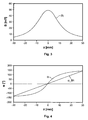
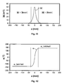
- Figure 2 shows the path of the components By and Bz of the magnetic flux density in accordance with the location z at which the permanent magnet 102 is located.
- the zero position is the position at which the permanent magnet 102 and the sensor 100 are directly opposite each other.
- the angle ⁇ which can be calculated in accordance with the following equation (1) is generally used as the measurement signal.
- ⁇ arctan B z B y
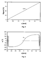
- the angle ⁇ depends comparatively linearly on the position of the permanent magnet 102 up to a given limit value in relation to the Hall sensor 100.
- the currently measured characteristic line is generally further linearised, as illustrated in Figure 4 by means of the line ⁇ _lin. That linearised line ⁇ _lin then forms the output characteristic line of the sensor.
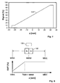
- Figure 5 shows the path of the position signal OUT output by the sensor.
- 3D Hall sensors can be operated only in the presence of a sufficiently powerful magnetic field. If the permanent magnet is located outside the detection range of the sensor, no sensor signal is available any longer.
- clamping voltages are not flexible enough for specific technical applications because they are fixedly preset and do not depend on the current measurement value.
- such fixedly set clamped measurement values are unsuitable when the sensor loses the magnetic field at the centre of the dynamic range, as occurs, for example, in H-bridge circuits in the automotive sector.
- An object of the present invention is to improve a measurement method and a displacement sensor of the type mentioned so that the displacement sensor can be used for a substantially greater deflection range and has optimised precision in a defined part-range of the deflection range without requiring a more powerful magnetic field source.
- the present invention is based on the notion that the magnetic field sensor is further provided with a storage unit which allows a valid sensor signal to be further output when the control by the magnetic field source is lost.
- the last position value still determined reliably is stored and output until the permanent magnet has moved again so far in the direction towards the sensor that it produces a sufficiently powerful magnetic field therein.
- the sensor according to the invention then outputs current measurement values again in place of the stored value.
- the senor according to the invention outputs a valid output signal at all times, it can theoretically be used for displacement paths of any size without subsequent hardware and software being disrupted by the signal which is outside permissible values.
- the measurement range actually involved is only relatively small, it is further possible to dispense with the selection of an unnecessarily large magnet which would be in a position to cover the entire displacement range.
- the advantages according to the invention can be achieved particularly readily if a two or three-dimensional Hall sensor is used as the magnetic field sensor and the magnetic field source comprises at least one permanent magnet.
- the magnitude of the magnetic flux density is monitored at the location of the sensor, it is possible in a particularly simple and efficient manner to determine the state in which the magnetic field source has reached an excessively large distance from the magnetic field sensor to still ensure a satisfactory signal-to-noise ratio. Since the sensor detects the individual magnetic field flux density components in any case, no additional technical measurement complexity is necessary for calculating the magnitude of the magnetic flux density, but instead only a calculation needs to be carried out.
- a displacement sensor arrangement is shown in Figure 1 .
- a Hall sensor 100 is mounted in a fixed position whilst a permanent magnet 102 is supported in a linearly movable manner in relation to the Hall sensor 100.
- the permanent magnet 102 is polarised in such a manner that its north/south axis is orientated parallel with the direction of movement. In principle, however, the principles of the present invention may also be applied to arrangements in which the permanent magnet 102 is polarised in such a manner that its north/south axis extends transversely to the direction of movement.
- the permanent magnet 102 can be displaced out of the zero position shown in Figure 1 in two directions by a displacement path 104 determined by the respective application.
- the Hall sensor 100 detects at least two orthogonal magnetic field components - one which extends along the movement line and one which extends transversely thereto (see Figure 2 ).
- Vector addition of the two components provides the magnitude of the magnetic field
- the angle ⁇ is defined as the angle which is enclosed by the total magnetic field vector
- the calculated angle ⁇ is linearised in order to be available as a displacement-proportional output signal OUT, as illustrated in Figures 4 and 5 .
- the principles according to the invention may also be transferred to other magnetic field sources, for example, electromagnets, and to other magnetic field sensors, such as magnetoresistive sensors or inductive sensors.
- the values of the magnetic field in the direction of movement Bz and, on the other hand, the values of the magnetic field transversely to the direction of movement By are used as the magnetic field components which are measured in accordance with the position of the permanent magnet 102 in the magnetic field sensor, in this instance a Hall sensor 100.
- the values Bx extending orthogonally to By can also be used for the calculation.
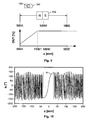
- Figure 6 shows the angle ⁇ calculated according to equation (1) for a more extensive displacement range between -40 and +40 mm for the arrangement of Figure 1 , in which the 3D Hall sensor 100 is positioned at the centre of the measurement path to be detected.
- the magnitude of the magnetic control field
- is at a maximum.
- the magnetic control field becomes very weak so that the values for By and Bz for calculating the angle become very small and accordingly the signal-to-noise ratio of both values becomes unfavourable for the calculation. This results in a great variation up to an oscillation of the value ⁇ at the measurement range ends, as illustrated in Figure 6 .
- is continuously monitored in many known sensors. If a value falls below a minimum value, the sensor signal is switched off or a value outside the admissible characteristic line range is output. This is illustrated in Figure 7 . In this instance, the sensor is switched off for a range z ⁇ -35 mm and z > +35 mm and the displacement position of the magnet can no longer be illustrated.
- the signal-to-noise ratios of the magnetic flux densities By or Bz therefore delimit the maximum possible displacement range of the magnet in those known sensors because the components of the magnetic flux density still have to be large enough to supply a meaningful measurement signal. Accordingly, the present invention proposes a 3D Hall sensor 102 having a storage unit 106.
- the output characteristic line can be produced in a substantially simpler manner and with a substantially smaller permanent magnet 102 by the sensor 100 being positioned directly in the partial measurement range between MBA and TMB1 and the movable magnet being configured to be only so large that its control field is sufficiently powerful for this partial measurement range.
- the sensor 100 has a storage device 106 which is in a position to function as a latch for storing the last current value ⁇ before the magnet leaves the detection range.
- the linearised output value OUT which may optionally be further processed in another manner can also be stored.
- the sensor outputs this value until the magnet 102 is brought back into the detection range of the sensor 100.
- the 3D Hall sensor 100 according to the invention is supplemented by a storage function of the last output value so that displacement ranges of the magnet which are infinitely large in theory are possible in the measurement arrangement with the sensor nevertheless behaving in a stable manner.
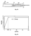
- Figure 10 shows the behaviour of the angle ⁇ with an extended displacement range of the magnet.
- the magnet leaving the detection range is evaluated by means of the magnitude of the flux density
- a delimitation to greater threshold values Bmin has the advantage that the signal-to-noise ratio is greater and the risk of disruptions is lower but has the disadvantage that the actual dynamic measurement range is narrower.
- Figure 15 shows a sensor arrangement which allows a precise measurement of the retraction position for controlling an end position in cylinder applications.
- the movable magnet 102 is secured to the cylinder piston 108 in this instance.
- the sensor 100 is located in the region of the end position which constitutes the measurement range which is really of interest.
- FIG. 17 and 18 Another advantageous application of the sensor arrangement according to the invention is illustrated in Figures 17 and 18 for the precise measurement of a central position or neutral position of selection levers.
- the displacement path of the permanent magnet 102 extends over a circular arc 110 in this instance, the selection lever 112 being connected to the permanent magnet 102.
- the sensor 100 is secured in such a manner that it is nearest the movable magnet 102 when the selection lever 112 is located in the zero position to be detected.
- the displacement path can extend, for example, in a range from -90° to +90° for the angle ⁇ .
- a comparatively small magnet 102 extends around it if valid measurement values are transmitted to subsequent electronic evaluation units in the edge regions which are not of interest in principle. This is carried out according to the invention in that the last measurement value before leaving the defined measurement range is stored and is output for the entire remaining displacement range.
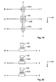
- FIG. 19 to 23 Another advantageous application is shown in Figures 19 to 23 .
- the arrangement according to the invention may also be used in an advantageous manner for precisely measuring a neutral position of H-bridge circuits in a car.
- an individual control magnet 102A, 102B, 102C is used for each gap.
- the sensor 100 stores the current value in the range of the central position until the magnet of the neighbouring gap is detected.
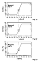
- the associated measurement signals are shown in Figures 21 to 23 .
- a hypothetical switching path from reverse gear R to 5 th gear 5 is schematically shown by a discontinuous line: first, the sensor 100 does not measure any magnetic field at all and therefore outputs as the output signal the last valid measurement value (produced by the magnet 102C). During further displacement in a positive z direction, the control field becomes large enough owing to the magnet 102C for the sensor 100 to output currently measured values. If the gap changes, the entire magnet arrangement of Figure 19 now moves in the x direction so that the B field measured at the sensor 100 falls below the threshold value
- the senor according to the invention has the advantage that it measures in a substantially more precise manner in a small partial measurement range but supplies measurement values which are valid over the entire displacement range to subsequent units and consequently can be used in a substantially broader environment. Furthermore, substantially smaller control magnets are sufficient for achieving the measurement objective. Furthermore, the storage function according to the invention also affords the possibility of storing any values which have currently been measured before the sensor has lost control by means of the magnetic field source even if that stored value is not at the upper or lower end of the measurement values occurring.
Landscapes
- Physics & Mathematics (AREA)
- General Physics & Mathematics (AREA)
- Transmission And Conversion Of Sensor Element Output (AREA)
- Measurement Of Length, Angles, Or The Like Using Electric Or Magnetic Means (AREA)
- Measuring Magnetic Variables (AREA)
Claims (11)
- Procédé de mesure sans contact de la position relative mutuelle d'une source de champ magnétique (102) qui produit un champ magnétique et d'un capteur de champ magnétique (100),
dans lequel la source de champ magnétique (102) et le capteur de champ magnétique (100) peuvent être déplacés l'un par rapport à l'autre,
dans lequel le capteur de champ magnétique (100) détecte au moins deux composantes spatiales (By, Bz) de la densité de flux magnétique du champ magnétique et un signal de position est produit à partir des composantes mesurées, et dans lequel le procédé comprend les étapes suivantes :calcul du signal de position sur base du quotient des deux composantes de densité de flux magnétique,calcul d'une grandeur de la densité de flux magnétique et comparaison de la grandeur à une valeur seuil prédéterminée,sortie du signal de position calculé actuel si la grandeur de la densité de flux magnétique est supérieure à la valeur seuil,sortie d'un signal de position stocké précédent si la grandeur de la densité de flux magnétique est inférieure ou égale à la valeur seuil,stockage du signal de position sorti. - Procédé selon la revendication 1, dans lequel le capteur de champ magnétique comprend un capteur à effet Hall à deux ou trois dimensions (100).
- Procédé selon l'une ou l'autre des revendications précédentes, dans lequel la source de champ magnétique comprend au moins un aimant permanent (102).
- Procédé selon l'une quelconque des revendications précédentes, dans lequel le calcul du signal de position comprend :l'établissement d'un angle α selon l'expression
 la linéarisation de l'angle de manière à produire un signal de sortie proportionnel au déplacement.
 - Procédé selon l'une quelconque des revendications précédentes, dans lequel le calcul de la grandeur de la densité de flux magnétique est mis en oeuvre en calculant la grandeur vectorielle à partir desdites au moins deux composantes spatiales (By, Bz) de la densité de flux magnétique du champ magnétique.
- Procédé selon l'une quelconque des revendications précédentes, dans lequel le stockage du signal de position comprend le stockage d'une valeur de l'angle

- Capteur de déplacement pour la mesure sans contact de la position relative mutuelle d'une source de champ magnétique (102) qui produit un champ magnétique et d'un capteur de champ magnétique (100),
dans lequel la source de champ magnétique (102) et le capteur de champ magnétique (100) peuvent être déplacés l'un par rapport à l'autre,
dans lequel le capteur de champ magnétique (100) est construit de manière à détecter au moins deux composantes spatiales (By, Bz) d'une densité de flux magnétique du champ magnétique et produit un signal de position à partir des composantes mesurées,
dans lequel le capteur de champ magnétique (100) comprend :une unité de commande et de calcul pour calculer le signal de position sur base du quotient des deux composantes de densité de flux magnétique, et pour calculer une grandeur de la densité de flux magnétique et comparer la grandeur à une valeur seuil prédéterminée, dans lequel l'unité de commande et de calcul peut être utilisée de manière à sortir le signal de position calculé actuel si la grandeur de la densité de flux magnétique est supérieure à la valeur seuil, et de manière à sortir un signal de position stocké précédent si la grandeur de la densité de flux magnétique est inférieure ou égale à la valeur seuil,une unité de stockage (106) pour stocker le signal de position sorti. - Capteur de déplacement selon la revendication 7, dans lequel le capteur de champ magnétique (100) comprend un capteur à effet Hall à deux ou trois dimensions.
- Capteur de déplacement selon l'une ou l'autre des revendications 7 et 8, dans lequel la source de champ magnétique (102) comprend au moins un aimant permanent.
- Capteur de déplacement selon l'une quelconque des revendications 7 à 9, dans lequel la source de champ magnétique (102) produit un champ magnétique qui est symétrique en rotation par rapport à un axe défini par un mouvement linéaire relatif entre la source de champ magnétique et le capteur de champ magnétique.
- Capteur de déplacement selon l'une quelconque des revendications 7 à 10, dans lequel la source de champ magnétique (102) et le capteur de champ magnétique (100) sont agencés dans une position nulle de telle sorte que le capteur de champ magnétique (100) est fixé dans une position où la grandeur de la densité de flux magnétique produite par la source de champ magnétique (102) est inférieure ou égale à la valeur seuil.
Applications Claiming Priority (2)
| Application Number | Priority Date | Filing Date | Title |
|---|---|---|---|
| DE102012203225A DE102012203225A1 (de) | 2012-03-01 | 2012-03-01 | Verfahren zum berührungslosen messen einer relativen position mittels eines 3d-hallsensors mit messsignalspeicher |
| PCT/EP2013/054134 WO2013127984A1 (fr) | 2012-03-01 | 2013-03-01 | Procédé pour la mesure sans contact d'une position relative au moyen d'un capteur 3d à effet hall ayant une mémoire destinée aux signaux de mesure |
Publications (2)
| Publication Number | Publication Date |
|---|---|
| EP2820384A1 EP2820384A1 (fr) | 2015-01-07 |
| EP2820384B1 true EP2820384B1 (fr) | 2015-08-12 |
Family
ID=47891626
Family Applications (1)
| Application Number | Title | Priority Date | Filing Date |
|---|---|---|---|
| EP13709809.1A Active EP2820384B1 (fr) | 2012-03-01 | 2013-03-01 | Procédé pour la mesure sans contact d'une position relative au moyen d'un capteur 3d à effet hall ayant une mémoire destinée aux signaux de mesure |
Country Status (6)
| Country | Link |
|---|---|
| US (1) | US9618318B2 (fr) |
| EP (1) | EP2820384B1 (fr) |
| JP (1) | JP6113197B2 (fr) |
| CN (1) | CN104204730B (fr) |
| DE (1) | DE102012203225A1 (fr) |
| WO (1) | WO2013127984A1 (fr) |
Families Citing this family (32)
| Publication number | Priority date | Publication date | Assignee | Title |
|---|---|---|---|---|
| DE102012205903B4 (de) | 2012-04-11 | 2014-01-30 | Tyco Electronics Amp Gmbh | Verfahren zum berührungslosen messen einer relativen position mittels eines magnetfeldsensorarrays auf halleffektbasis und weggeber |
| JP5595613B1 (ja) * | 2014-03-20 | 2014-09-24 | 三菱重工業株式会社 | 歯車の位相算出装置、歯車の位相算出方法、及び、歯車加工装置 |
| DE102014205566A1 (de) * | 2014-03-26 | 2015-10-01 | Robert Bosch Gmbh | Sensoranordnung zur Wegerfassung an einem bewegten Bauteil |
| GB2532787A (en) * | 2014-11-28 | 2016-06-01 | Ibm | Sensor arrangement for position sensing |
| CN107810389B (zh) * | 2015-06-11 | 2021-04-16 | 费斯托股份两合公司 | 带有检测设备的驱动装置和方法 |
| FR3039269B1 (fr) * | 2015-07-21 | 2017-08-11 | Electricfil Automotive | Capteur de mesure de la position absolue d'un mobile |
| JP6030199B1 (ja) * | 2015-08-28 | 2016-11-24 | 栄通信工業株式会社 | 直線摺動ポテンショメータ |
| CN106524887B (zh) * | 2015-09-14 | 2019-04-19 | 上海汽车集团股份有限公司 | 霍尔传感器测量位移的方法及装置 |
| EP3458805B1 (fr) | 2016-05-17 | 2020-09-23 | Kongsberg Inc. | Système, procédé et objet servant à la détection de position magnétique à haute précision |
| DE102016110968B4 (de) * | 2016-06-15 | 2019-05-02 | Sick Ag | Sensor |
| KR101963106B1 (ko) | 2016-11-29 | 2019-04-01 | 주식회사 해치텍 | 회전각 검출 장치 |
| JP6291638B1 (ja) * | 2016-12-07 | 2018-03-14 | 小野 瑞絵 | 磁気力測定装置 |
| FR3070486A1 (fr) * | 2017-08-31 | 2019-03-01 | Valeo Systemes De Controle Moteur | Procede de calibration d'un dispositif magnetique de determination de la position d'une piece en translation |
| DE102017128548A1 (de) * | 2017-12-01 | 2019-06-06 | Sick Ag | Sensor |
| US11662227B2 (en) | 2018-01-12 | 2023-05-30 | Honeywell International Inc. | Magnetic encoding for smart position sensor range extension |
| CN108917720B (zh) * | 2018-05-15 | 2020-07-03 | 天津大学 | 一种管道俯仰角测量装置及测量方法 |
| US11532470B2 (en) * | 2018-11-27 | 2022-12-20 | Taiwan Semiconductor Manufacturing Company Ltd. | Analyzing method |
| JP6992771B2 (ja) * | 2019-01-29 | 2022-01-13 | Tdk株式会社 | 磁気ユニット、位置検出装置および磁気部材 |
| JP2020144086A (ja) * | 2019-03-08 | 2020-09-10 | ジオマテック株式会社 | 流体残量検出装置及び流体容器 |
| DE102019112572A1 (de) * | 2019-05-14 | 2020-11-19 | HELLA GmbH & Co. KGaA | Vorrichtung und Verfahren zur kontaktlosen Bestimmung einer Position eines Pedals |
| WO2021161066A1 (fr) | 2020-02-11 | 2021-08-19 | Ka Group Ag | Capteur de couple magnétoélastique à mesure locale du champ magnétique ambiant |
| DE102020104297A1 (de) | 2020-02-19 | 2021-08-19 | Kiekert Aktiengesellschaft | Kraftfahrzeug-Schließeinrichtung |
| CN111322991B (zh) * | 2020-04-16 | 2021-07-20 | 赤峰华源新力科技有限公司 | 一种基于三维霍尔传感器测量风电塔筒倾角的系统 |
| CN113853729A (zh) * | 2020-08-26 | 2021-12-28 | 深圳市大疆创新科技有限公司 | 电机转子的旋转角度的测量方法、测量装置以及电机、云台和无人飞行器 |
| CN112229314A (zh) * | 2020-11-13 | 2021-01-15 | 广州市雅江光电设备有限公司 | 一种霍尔元件的感应区间中间点的定位方法 |
| CN112985353B (zh) * | 2021-05-20 | 2021-09-07 | 浙江图维科技股份有限公司 | 一种基于电磁检测的电缆防沉降位移监测方法及系统 |
| CN113776416B (zh) * | 2021-08-27 | 2024-02-06 | 浙江沃德尔科技集团股份有限公司 | 一种抗磁场干扰的非接触式踏板位置的检测装置 |
| CN116045798A (zh) * | 2022-07-30 | 2023-05-02 | 荣耀终端有限公司 | 一种角度检测装置、电子设备及角度检测方法 |
| EP4391383A1 (fr) * | 2022-12-23 | 2024-06-26 | Melexis Bulgaria EOOD | Commutateur magnétique et détection de proximité |
| DE102023111648A1 (de) * | 2023-05-04 | 2024-11-07 | Kiekert Aktiengesellschaft | Kraftfahrzeug-Schließeinrichtung |
| EP4580060A1 (fr) * | 2023-12-28 | 2025-07-02 | Melexis Bulgaria EOOD | Commutateur magnétique |
| JP2025151363A (ja) | 2024-03-28 | 2025-10-09 | アルプスアルパイン株式会社 | 磁気センサおよび磁気測定方法 |
Family Cites Families (17)
| Publication number | Priority date | Publication date | Assignee | Title |
|---|---|---|---|---|
| US4606008A (en) * | 1983-07-25 | 1986-08-12 | Cain Encoder Company | Angular position detector |
| US5442283A (en) * | 1993-09-03 | 1995-08-15 | Allegro Microsystems, Inc. | Hall-voltage slope-activated sensor |
| DE19836599A1 (de) | 1998-08-13 | 2000-02-17 | Windhorst Beteiligungsgesellsc | Verfahren zur berührungslosen magnetischen Erfassung linearer Relativbewegungen zwischen Dauermagneten und elektronischen Sensoren |
| JP3491587B2 (ja) | 1999-12-21 | 2004-01-26 | 株式会社デンソー | 回転角度検出センサのフェイルモード調整方法 |
| JP4936299B2 (ja) * | 2000-08-21 | 2012-05-23 | メレクシス・テクノロジーズ・ナムローゼフェンノートシャップ | 磁場方向検出センサ |
| EP1243897B1 (fr) | 2001-03-23 | 2013-12-18 | Melexis Technologies NV | Capteur de position magnétique |
| KR100564866B1 (ko) * | 2002-03-22 | 2006-03-28 | 아사히 가세이 일렉트로닉스 가부시끼가이샤 | 각도 검출 장치 및 각도 검출 시스템 |
| CN100443913C (zh) * | 2002-11-13 | 2008-12-17 | 松下电器产业株式会社 | 磁场传感器和磁场检测装置及磁场检测方法 |
| GB0305352D0 (en) * | 2003-03-08 | 2003-04-16 | Melexis Nv | Hall effect sensor |
| FR2935478B1 (fr) * | 2008-08-28 | 2010-09-10 | Roulements Soc Nouvelle | Systeme et procede de mesure du mouvement axial d'une piece mobile en rotation |
| DE102008045177A1 (de) | 2008-08-30 | 2010-03-04 | Festo Ag & Co. Kg | Messverfahren zur berührungslosen Erfassung linearer Relativbewegungen zwischen einer Sensoranordnung und einem Permanentmagneten |
| EP2166312B2 (fr) * | 2008-09-18 | 2020-01-15 | Sick Ag | Capteur de trajectoire magnétique ou inductif |
| DE102009028170A1 (de) * | 2009-07-31 | 2011-02-10 | Robert Bosch Gmbh | Kommutierter elektrischer Antrieb und Verfahren zur Ansteuerung eines kommutierten Elektromotors |
| DE102010003292A1 (de) | 2010-03-25 | 2011-09-29 | Fraunhofer-Gesellschaft zur Förderung der angewandten Forschung e.V. | Sensoranordnung und Verfahren zum Ermitteln einer Magnetisierungseinrichtung eines Gebermagneten |
| US8335659B2 (en) * | 2010-07-15 | 2012-12-18 | Tyco Electronics Corporation | Linear position sensor system |
| JP5594086B2 (ja) * | 2010-11-19 | 2014-09-24 | アイシン精機株式会社 | 変位検出装置 |
| DE102012205903B4 (de) * | 2012-04-11 | 2014-01-30 | Tyco Electronics Amp Gmbh | Verfahren zum berührungslosen messen einer relativen position mittels eines magnetfeldsensorarrays auf halleffektbasis und weggeber |
-
2012
- 2012-03-01 DE DE102012203225A patent/DE102012203225A1/de not_active Withdrawn
-
2013
- 2013-03-01 WO PCT/EP2013/054134 patent/WO2013127984A1/fr not_active Ceased
- 2013-03-01 EP EP13709809.1A patent/EP2820384B1/fr active Active
- 2013-03-01 JP JP2014559237A patent/JP6113197B2/ja active Active
- 2013-03-01 US US14/381,911 patent/US9618318B2/en active Active
- 2013-03-01 CN CN201380016198.6A patent/CN104204730B/zh active Active
Also Published As
| Publication number | Publication date |
|---|---|
| JP2015512040A (ja) | 2015-04-23 |
| CN104204730B (zh) | 2016-08-17 |
| US9618318B2 (en) | 2017-04-11 |
| WO2013127984A1 (fr) | 2013-09-06 |
| EP2820384A1 (fr) | 2015-01-07 |
| CN104204730A (zh) | 2014-12-10 |
| US20150046117A1 (en) | 2015-02-12 |
| JP6113197B2 (ja) | 2017-04-12 |
| DE102012203225A1 (de) | 2013-09-05 |
Similar Documents
| Publication | Publication Date | Title |
|---|---|---|
| EP2820384B1 (fr) | Procédé pour la mesure sans contact d'une position relative au moyen d'un capteur 3d à effet hall ayant une mémoire destinée aux signaux de mesure | |
| US9982988B2 (en) | Displacement sensor for contactlessly measuring a relative position by means of a magnetic field sensor array on the basis of the hall effect | |
| US9360537B2 (en) | Method for contactless measurement of a relative position by means of a hall sensor | |
| US9335149B2 (en) | Displacement sensor for contactlessly measuring a position by means of a plurality of magnetic field sensors arranged in series | |
| EP3370038B1 (fr) | Dispositif de détection de position | |
| US9835472B2 (en) | Using cartesian coordinates for position detection with a magnetic sensor | |
| US8970210B2 (en) | Bidirectional magnetic position sensor having field rotation | |
| US10571305B2 (en) | Method for determining the position of a magnet relative to a row of sensors | |
| WO2013036501A1 (fr) | Capteur de position linéaire | |
| WO2015063138A1 (fr) | Procédé de compensation de température de champs magnétiques de commande dans un capteur à effet hall avec adaptation os | |
| CN104422386A (zh) | 旋转检测装置 | |
| EP2843358A1 (fr) | Dispositif d'aimant et système de détection de position | |
| US20130241575A1 (en) | Electric machine | |
| CN115053079A (zh) | 位置检测装置 | |
| US8878530B2 (en) | Measurement method and magnetic sensor for the contactless detection of movements | |
| US20160238672A1 (en) | Temperature Compensation Method Of Magnetic Control Fields In a Hall Sensor With OS Adaption | |
| EP4034842B1 (fr) | Agencement de mesure de déplacement doté d'un capteur à effet hall et d'un aimant | |
| EP3839693A1 (fr) | Bâton de commande, système de capteur et procédé correspondant | |
| EP4174445B1 (fr) | Dispositif de détection de position | |
| JP2017096756A (ja) | ストローク検出装置 | |
| JP2009236743A (ja) | 磁気式位置検出装置 | |
| JP2017116408A (ja) | ストローク検出装置 |
Legal Events
| Date | Code | Title | Description |
|---|---|---|---|
| PUAI | Public reference made under article 153(3) epc to a published international application that has entered the european phase |
Free format text: ORIGINAL CODE: 0009012 |
|
| 17P | Request for examination filed |
Effective date: 20140930 |
|
| AK | Designated contracting states |
Kind code of ref document: A1 Designated state(s): AL AT BE BG CH CY CZ DE DK EE ES FI FR GB GR HR HU IE IS IT LI LT LU LV MC MK MT NL NO PL PT RO RS SE SI SK SM TR |
|
| AX | Request for extension of the european patent |
Extension state: BA ME |
|
| REG | Reference to a national code |
Ref country code: DE Ref legal event code: R079 Ref document number: 602013002644 Country of ref document: DE Free format text: PREVIOUS MAIN CLASS: G01D0005244000 Ipc: G01D0005140000 |
|
| GRAP | Despatch of communication of intention to grant a patent |
Free format text: ORIGINAL CODE: EPIDOSNIGR1 |
|
| RIC1 | Information provided on ipc code assigned before grant |
Ipc: G01B 7/30 20060101ALI20150227BHEP Ipc: G01D 5/244 20060101ALI20150227BHEP Ipc: G01B 7/004 20060101ALI20150227BHEP Ipc: G01D 5/14 20060101AFI20150227BHEP |
|
| DAX | Request for extension of the european patent (deleted) | ||
| INTG | Intention to grant announced |
Effective date: 20150324 |
|
| GRAS | Grant fee paid |
Free format text: ORIGINAL CODE: EPIDOSNIGR3 |
|
| GRAA | (expected) grant |
Free format text: ORIGINAL CODE: 0009210 |
|
| AK | Designated contracting states |
Kind code of ref document: B1 Designated state(s): AL AT BE BG CH CY CZ DE DK EE ES FI FR GB GR HR HU IE IS IT LI LT LU LV MC MK MT NL NO PL PT RO RS SE SI SK SM TR |
|
| REG | Reference to a national code |
Ref country code: GB Ref legal event code: FG4D |
|
| REG | Reference to a national code |
Ref country code: CH Ref legal event code: EP |
|
| REG | Reference to a national code |
Ref country code: AT Ref legal event code: REF Ref document number: 742574 Country of ref document: AT Kind code of ref document: T Effective date: 20150815 |
|
| RAP2 | Party data changed (patent owner data changed or rights of a patent transferred) |
Owner name: TE CONNECTIVITY GERMANY GMBH |
|
| REG | Reference to a national code |
Ref country code: IE Ref legal event code: FG4D |
|
| REG | Reference to a national code |
Ref country code: DE Ref legal event code: R096 Ref document number: 602013002644 Country of ref document: DE |
|
| REG | Reference to a national code |
Ref country code: LT Ref legal event code: MG4D |
|
| REG | Reference to a national code |
Ref country code: AT Ref legal event code: MK05 Ref document number: 742574 Country of ref document: AT Kind code of ref document: T Effective date: 20150812 |
|
| REG | Reference to a national code |
Ref country code: NL Ref legal event code: MP Effective date: 20150812 |
|
| PG25 | Lapsed in a contracting state [announced via postgrant information from national office to epo] |
Ref country code: FI Free format text: LAPSE BECAUSE OF FAILURE TO SUBMIT A TRANSLATION OF THE DESCRIPTION OR TO PAY THE FEE WITHIN THE PRESCRIBED TIME-LIMIT Effective date: 20150812 Ref country code: LT Free format text: LAPSE BECAUSE OF FAILURE TO SUBMIT A TRANSLATION OF THE DESCRIPTION OR TO PAY THE FEE WITHIN THE PRESCRIBED TIME-LIMIT Effective date: 20150812 Ref country code: GR Free format text: LAPSE BECAUSE OF FAILURE TO SUBMIT A TRANSLATION OF THE DESCRIPTION OR TO PAY THE FEE WITHIN THE PRESCRIBED TIME-LIMIT Effective date: 20151113 Ref country code: NO Free format text: LAPSE BECAUSE OF FAILURE TO SUBMIT A TRANSLATION OF THE DESCRIPTION OR TO PAY THE FEE WITHIN THE PRESCRIBED TIME-LIMIT Effective date: 20151112 Ref country code: LV Free format text: LAPSE BECAUSE OF FAILURE TO SUBMIT A TRANSLATION OF THE DESCRIPTION OR TO PAY THE FEE WITHIN THE PRESCRIBED TIME-LIMIT Effective date: 20150812 |
|
| PG25 | Lapsed in a contracting state [announced via postgrant information from national office to epo] |
Ref country code: SE Free format text: LAPSE BECAUSE OF FAILURE TO SUBMIT A TRANSLATION OF THE DESCRIPTION OR TO PAY THE FEE WITHIN THE PRESCRIBED TIME-LIMIT Effective date: 20150812 Ref country code: AT Free format text: LAPSE BECAUSE OF FAILURE TO SUBMIT A TRANSLATION OF THE DESCRIPTION OR TO PAY THE FEE WITHIN THE PRESCRIBED TIME-LIMIT Effective date: 20150812 Ref country code: IS Free format text: LAPSE BECAUSE OF FAILURE TO SUBMIT A TRANSLATION OF THE DESCRIPTION OR TO PAY THE FEE WITHIN THE PRESCRIBED TIME-LIMIT Effective date: 20151212 Ref country code: ES Free format text: LAPSE BECAUSE OF FAILURE TO SUBMIT A TRANSLATION OF THE DESCRIPTION OR TO PAY THE FEE WITHIN THE PRESCRIBED TIME-LIMIT Effective date: 20150812 Ref country code: PL Free format text: LAPSE BECAUSE OF FAILURE TO SUBMIT A TRANSLATION OF THE DESCRIPTION OR TO PAY THE FEE WITHIN THE PRESCRIBED TIME-LIMIT Effective date: 20150812 Ref country code: RS Free format text: LAPSE BECAUSE OF FAILURE TO SUBMIT A TRANSLATION OF THE DESCRIPTION OR TO PAY THE FEE WITHIN THE PRESCRIBED TIME-LIMIT Effective date: 20150812 Ref country code: HR Free format text: LAPSE BECAUSE OF FAILURE TO SUBMIT A TRANSLATION OF THE DESCRIPTION OR TO PAY THE FEE WITHIN THE PRESCRIBED TIME-LIMIT Effective date: 20150812 Ref country code: PT Free format text: LAPSE BECAUSE OF FAILURE TO SUBMIT A TRANSLATION OF THE DESCRIPTION OR TO PAY THE FEE WITHIN THE PRESCRIBED TIME-LIMIT Effective date: 20151214 |
|
| REG | Reference to a national code |
Ref country code: FR Ref legal event code: PLFP Year of fee payment: 4 |
|
| PG25 | Lapsed in a contracting state [announced via postgrant information from national office to epo] |
Ref country code: NL Free format text: LAPSE BECAUSE OF FAILURE TO SUBMIT A TRANSLATION OF THE DESCRIPTION OR TO PAY THE FEE WITHIN THE PRESCRIBED TIME-LIMIT Effective date: 20150812 |
|
| PG25 | Lapsed in a contracting state [announced via postgrant information from national office to epo] |
Ref country code: CZ Free format text: LAPSE BECAUSE OF FAILURE TO SUBMIT A TRANSLATION OF THE DESCRIPTION OR TO PAY THE FEE WITHIN THE PRESCRIBED TIME-LIMIT Effective date: 20150812 Ref country code: EE Free format text: LAPSE BECAUSE OF FAILURE TO SUBMIT A TRANSLATION OF THE DESCRIPTION OR TO PAY THE FEE WITHIN THE PRESCRIBED TIME-LIMIT Effective date: 20150812 Ref country code: DK Free format text: LAPSE BECAUSE OF FAILURE TO SUBMIT A TRANSLATION OF THE DESCRIPTION OR TO PAY THE FEE WITHIN THE PRESCRIBED TIME-LIMIT Effective date: 20150812 Ref country code: SK Free format text: LAPSE BECAUSE OF FAILURE TO SUBMIT A TRANSLATION OF THE DESCRIPTION OR TO PAY THE FEE WITHIN THE PRESCRIBED TIME-LIMIT Effective date: 20150812 |
|
| REG | Reference to a national code |
Ref country code: DE Ref legal event code: R097 Ref document number: 602013002644 Country of ref document: DE |
|
| PG25 | Lapsed in a contracting state [announced via postgrant information from national office to epo] |
Ref country code: RO Free format text: LAPSE BECAUSE OF FAILURE TO SUBMIT A TRANSLATION OF THE DESCRIPTION OR TO PAY THE FEE WITHIN THE PRESCRIBED TIME-LIMIT Effective date: 20150812 |
|
| PLBE | No opposition filed within time limit |
Free format text: ORIGINAL CODE: 0009261 |
|
| STAA | Information on the status of an ep patent application or granted ep patent |
Free format text: STATUS: NO OPPOSITION FILED WITHIN TIME LIMIT |
|
| 26N | No opposition filed |
Effective date: 20160513 |
|
| PG25 | Lapsed in a contracting state [announced via postgrant information from national office to epo] |
Ref country code: SI Free format text: LAPSE BECAUSE OF FAILURE TO SUBMIT A TRANSLATION OF THE DESCRIPTION OR TO PAY THE FEE WITHIN THE PRESCRIBED TIME-LIMIT Effective date: 20150812 Ref country code: BE Free format text: LAPSE BECAUSE OF NON-PAYMENT OF DUE FEES Effective date: 20160331 |
|
| PG25 | Lapsed in a contracting state [announced via postgrant information from national office to epo] |
Ref country code: MC Free format text: LAPSE BECAUSE OF FAILURE TO SUBMIT A TRANSLATION OF THE DESCRIPTION OR TO PAY THE FEE WITHIN THE PRESCRIBED TIME-LIMIT Effective date: 20150812 Ref country code: LU Free format text: LAPSE BECAUSE OF FAILURE TO SUBMIT A TRANSLATION OF THE DESCRIPTION OR TO PAY THE FEE WITHIN THE PRESCRIBED TIME-LIMIT Effective date: 20160301 |
|
| REG | Reference to a national code |
Ref country code: CH Ref legal event code: PL |
|
| REG | Reference to a national code |
Ref country code: IE Ref legal event code: MM4A |
|
| PG25 | Lapsed in a contracting state [announced via postgrant information from national office to epo] |
Ref country code: BE Free format text: LAPSE BECAUSE OF FAILURE TO SUBMIT A TRANSLATION OF THE DESCRIPTION OR TO PAY THE FEE WITHIN THE PRESCRIBED TIME-LIMIT Effective date: 20150812 |
|
| PG25 | Lapsed in a contracting state [announced via postgrant information from national office to epo] |
Ref country code: CH Free format text: LAPSE BECAUSE OF NON-PAYMENT OF DUE FEES Effective date: 20160331 Ref country code: IE Free format text: LAPSE BECAUSE OF NON-PAYMENT OF DUE FEES Effective date: 20160301 Ref country code: LI Free format text: LAPSE BECAUSE OF NON-PAYMENT OF DUE FEES Effective date: 20160331 |
|
| REG | Reference to a national code |
Ref country code: FR Ref legal event code: PLFP Year of fee payment: 5 |
|
| PG25 | Lapsed in a contracting state [announced via postgrant information from national office to epo] |
Ref country code: MT Free format text: LAPSE BECAUSE OF FAILURE TO SUBMIT A TRANSLATION OF THE DESCRIPTION OR TO PAY THE FEE WITHIN THE PRESCRIBED TIME-LIMIT Effective date: 20150812 |
|
| GBPC | Gb: european patent ceased through non-payment of renewal fee |
Effective date: 20170301 |
|
| REG | Reference to a national code |
Ref country code: FR Ref legal event code: PLFP Year of fee payment: 6 |
|
| PG25 | Lapsed in a contracting state [announced via postgrant information from national office to epo] |
Ref country code: GB Free format text: LAPSE BECAUSE OF NON-PAYMENT OF DUE FEES Effective date: 20170301 |
|
| PG25 | Lapsed in a contracting state [announced via postgrant information from national office to epo] |
Ref country code: HU Free format text: LAPSE BECAUSE OF FAILURE TO SUBMIT A TRANSLATION OF THE DESCRIPTION OR TO PAY THE FEE WITHIN THE PRESCRIBED TIME-LIMIT; INVALID AB INITIO Effective date: 20130301 Ref country code: SM Free format text: LAPSE BECAUSE OF FAILURE TO SUBMIT A TRANSLATION OF THE DESCRIPTION OR TO PAY THE FEE WITHIN THE PRESCRIBED TIME-LIMIT Effective date: 20150812 |
|
| PG25 | Lapsed in a contracting state [announced via postgrant information from national office to epo] |
Ref country code: MK Free format text: LAPSE BECAUSE OF FAILURE TO SUBMIT A TRANSLATION OF THE DESCRIPTION OR TO PAY THE FEE WITHIN THE PRESCRIBED TIME-LIMIT Effective date: 20150812 Ref country code: CY Free format text: LAPSE BECAUSE OF FAILURE TO SUBMIT A TRANSLATION OF THE DESCRIPTION OR TO PAY THE FEE WITHIN THE PRESCRIBED TIME-LIMIT Effective date: 20150812 Ref country code: MT Free format text: LAPSE BECAUSE OF FAILURE TO SUBMIT A TRANSLATION OF THE DESCRIPTION OR TO PAY THE FEE WITHIN THE PRESCRIBED TIME-LIMIT Effective date: 20160331 |
|
| PG25 | Lapsed in a contracting state [announced via postgrant information from national office to epo] |
Ref country code: BG Free format text: LAPSE BECAUSE OF FAILURE TO SUBMIT A TRANSLATION OF THE DESCRIPTION OR TO PAY THE FEE WITHIN THE PRESCRIBED TIME-LIMIT Effective date: 20150812 |
|
| PG25 | Lapsed in a contracting state [announced via postgrant information from national office to epo] |
Ref country code: TR Free format text: LAPSE BECAUSE OF FAILURE TO SUBMIT A TRANSLATION OF THE DESCRIPTION OR TO PAY THE FEE WITHIN THE PRESCRIBED TIME-LIMIT Effective date: 20150812 Ref country code: AL Free format text: LAPSE BECAUSE OF FAILURE TO SUBMIT A TRANSLATION OF THE DESCRIPTION OR TO PAY THE FEE WITHIN THE PRESCRIBED TIME-LIMIT Effective date: 20150812 |
|
| PGFP | Annual fee paid to national office [announced via postgrant information from national office to epo] |
Ref country code: IT Payment date: 20200221 Year of fee payment: 8 |
|
| PG25 | Lapsed in a contracting state [announced via postgrant information from national office to epo] |
Ref country code: IT Free format text: LAPSE BECAUSE OF NON-PAYMENT OF DUE FEES Effective date: 20210301 |
|
| PGFP | Annual fee paid to national office [announced via postgrant information from national office to epo] |
Ref country code: FR Payment date: 20241231 Year of fee payment: 13 |
|
| PGFP | Annual fee paid to national office [announced via postgrant information from national office to epo] |
Ref country code: DE Payment date: 20260102 Year of fee payment: 14 |