EP3370038B1 - Dispositif de détection de position - Google Patents
Dispositif de détection de position Download PDFInfo
- Publication number
- EP3370038B1 EP3370038B1 EP16859388.7A EP16859388A EP3370038B1 EP 3370038 B1 EP3370038 B1 EP 3370038B1 EP 16859388 A EP16859388 A EP 16859388A EP 3370038 B1 EP3370038 B1 EP 3370038B1
- Authority
- EP
- European Patent Office
- Prior art keywords
- movement trajectory
- magnet
- detection unit
- detection device
- position detection
- Prior art date
- Legal status (The legal status is an assumption and is not a legal conclusion. Google has not performed a legal analysis and makes no representation as to the accuracy of the status listed.)
- Active
Links
Images



Classifications
-
- G—PHYSICS
- G01—MEASURING; TESTING
- G01B—MEASURING LENGTH, THICKNESS OR SIMILAR LINEAR DIMENSIONS; MEASURING ANGLES; MEASURING AREAS; MEASURING IRREGULARITIES OF SURFACES OR CONTOURS
- G01B5/00—Measuring arrangements characterised by the use of mechanical techniques
- G01B5/0011—Arrangements for eliminating or compensation of measuring errors due to temperature or weight
- G01B5/0014—Arrangements for eliminating or compensation of measuring errors due to temperature or weight due to temperature
-
- G—PHYSICS
- G01—MEASURING; TESTING
- G01B—MEASURING LENGTH, THICKNESS OR SIMILAR LINEAR DIMENSIONS; MEASURING ANGLES; MEASURING AREAS; MEASURING IRREGULARITIES OF SURFACES OR CONTOURS
- G01B7/00—Measuring arrangements characterised by the use of electric or magnetic techniques
- G01B7/003—Measuring arrangements characterised by the use of electric or magnetic techniques for measuring position, not involving coordinate determination
-
- G—PHYSICS
- G01—MEASURING; TESTING
- G01D—MEASURING NOT SPECIALLY ADAPTED FOR A SPECIFIC VARIABLE; ARRANGEMENTS FOR MEASURING TWO OR MORE VARIABLES NOT COVERED IN A SINGLE OTHER SUBCLASS; TARIFF METERING APPARATUS; MEASURING OR TESTING NOT OTHERWISE PROVIDED FOR
- G01D3/00—Indicating or recording apparatus with provision for the special purposes referred to in the subgroups
- G01D3/028—Indicating or recording apparatus with provision for the special purposes referred to in the subgroups mitigating undesired influences, e.g. temperature, pressure
- G01D3/036—Indicating or recording apparatus with provision for the special purposes referred to in the subgroups mitigating undesired influences, e.g. temperature, pressure on measuring arrangements themselves
-
- G—PHYSICS
- G01—MEASURING; TESTING
- G01D—MEASURING NOT SPECIALLY ADAPTED FOR A SPECIFIC VARIABLE; ARRANGEMENTS FOR MEASURING TWO OR MORE VARIABLES NOT COVERED IN A SINGLE OTHER SUBCLASS; TARIFF METERING APPARATUS; MEASURING OR TESTING NOT OTHERWISE PROVIDED FOR
- G01D5/00—Mechanical means for transferring the output of a sensing member; Means for converting the output of a sensing member to another variable where the form or nature of the sensing member does not constrain the means for converting; Transducers not specially adapted for a specific variable
- G01D5/12—Mechanical means for transferring the output of a sensing member; Means for converting the output of a sensing member to another variable where the form or nature of the sensing member does not constrain the means for converting; Transducers not specially adapted for a specific variable using electric or magnetic means
-
- G—PHYSICS
- G01—MEASURING; TESTING
- G01D—MEASURING NOT SPECIALLY ADAPTED FOR A SPECIFIC VARIABLE; ARRANGEMENTS FOR MEASURING TWO OR MORE VARIABLES NOT COVERED IN A SINGLE OTHER SUBCLASS; TARIFF METERING APPARATUS; MEASURING OR TESTING NOT OTHERWISE PROVIDED FOR
- G01D5/00—Mechanical means for transferring the output of a sensing member; Means for converting the output of a sensing member to another variable where the form or nature of the sensing member does not constrain the means for converting; Transducers not specially adapted for a specific variable
- G01D5/12—Mechanical means for transferring the output of a sensing member; Means for converting the output of a sensing member to another variable where the form or nature of the sensing member does not constrain the means for converting; Transducers not specially adapted for a specific variable using electric or magnetic means
- G01D5/14—Mechanical means for transferring the output of a sensing member; Means for converting the output of a sensing member to another variable where the form or nature of the sensing member does not constrain the means for converting; Transducers not specially adapted for a specific variable using electric or magnetic means influencing the magnitude of a current or voltage
- G01D5/142—Mechanical means for transferring the output of a sensing member; Means for converting the output of a sensing member to another variable where the form or nature of the sensing member does not constrain the means for converting; Transducers not specially adapted for a specific variable using electric or magnetic means influencing the magnitude of a current or voltage using Hall-effect devices
- G01D5/145—Mechanical means for transferring the output of a sensing member; Means for converting the output of a sensing member to another variable where the form or nature of the sensing member does not constrain the means for converting; Transducers not specially adapted for a specific variable using electric or magnetic means influencing the magnitude of a current or voltage using Hall-effect devices influenced by the relative movement between the Hall device and magnetic fields
-
- G—PHYSICS
- G01—MEASURING; TESTING
- G01R—MEASURING ELECTRIC VARIABLES; MEASURING MAGNETIC VARIABLES
- G01R33/00—Arrangements or instruments for measuring magnetic variables
- G01R33/02—Measuring direction or magnitude of magnetic fields or magnetic flux
-
- G—PHYSICS
- G01—MEASURING; TESTING
- G01R—MEASURING ELECTRIC VARIABLES; MEASURING MAGNETIC VARIABLES
- G01R33/00—Arrangements or instruments for measuring magnetic variables
- G01R33/02—Measuring direction or magnitude of magnetic fields or magnetic flux
- G01R33/06—Measuring direction or magnitude of magnetic fields or magnetic flux using galvano-magnetic devices
- G01R33/09—Magnetoresistive devices
Definitions
- the present invention relates to a position detection device that detects the relative positions and movement of a magnet and a detection unit having a magnetic sensor.
- PTL 1 describes an invention relating to a position detection device.
- the position detection device has a case accommodating a holder that moves to advance and retreat, and the holder is provided with two magnets that are arranged side by side in a moving direction.
- a detection unit is fixed to the case.
- the detection unit is provided with two magnetoresistive elements facing the magnets that move.
- the holder is urged by a compression coil spring in a direction in which the holder projects from the case.
- a shaft integrally formed with the holder is pressed to move the case in a direction against the urging direction of the compression coil spring, the movement of the magnets is detected with the magnetoresistive elements and the moving position of the holder is calculated.
- US 2010/188074 A1 discloses a stroke sensor which has two magnets which are magnetized in a cross-section direction and are displaced in a longitudinal direction, and two magnetism sensitive sections arranged parallel to the longitudinal direction.
- the magnets have circular-arc-shaped swelling end edges respectively and are magnetized such that the swelling end edges have opposite polarities.
- a distribution of a magnetic flux density on an arrangement axis substantially coincides with a sine curve.
- the magnetic flux having such the distribution is displaced in the longitudinal direction together with the magnets.
- the magnetism sensitive sections are arranged on the arrangement axis to be distant from each other by a distance of one fourth of a cycle of the sine curve.
- the present invention relates to a position detection device according to the appended claims.
- the magnetoresistive elements detect a component (Bz) and a component (Bx) of the magnetic flux density of a leakage magnetic field generated by the two magnets, the component (Bz) being in a direction perpendicular to the direction in which the holder moves, the component (Bx) being in a direction parallel to the direction in which the holder moves, to calculate the moving position of the holder. For example, an arc tangent is computed from the detected value of the component (Bz) and the detected value of the component (Bx), and the position of the holder is determined from the computed value.
- the intensity of the leakage magnetic field from the magnets is affected by temperature, and a demagnetization phenomenon in which the magnetic flux density of the leakage magnetic field decreases occurs at a high temperature. It is conventionally recognized that the rate at which the magnetic flux density decreases when a rectangular parallelepiped magnet is heated is always in the same proportion for the component (Bz) in the direction perpendicular to a magnetized surface and the component (Bx) in the direction parallel to the magnetized surface.
- the present invention is intended to address the conventional problem described above, and it is an object of the present invention to provide a position detection device having a structure that makes it easy to ensure the linearity of detection values for detecting the relative movement of a magnet and a detection unit even when a temperature change causes demagnetization of the magnet.
- the present invention provides a position detection device including a detection unit and a magnet facing the detection unit, the detection unit and the magnet being movable relatively to each other, wherein the magnet is magnetized in a direction perpendicular to a relative movement trajectory of the detection unit, and the detection unit includes a magnetic sensor that detects a component of magnetic flux emerging from the magnet that is parallel to the movement trajectory, and a magnetic sensor that detects a component of the magnetic flux that is perpendicular to the movement trajectory, and wherein the magnet has a facing surface facing the movement trajectory, and both ends of the facing surface in a direction extending along the movement trajectory are positioned farther away from the movement trajectory than a center portion of the facing surface.
- the facing surface is a projecting curved surface having a curvature in a direction extending along the movement trajectory.
- the curvature has a radius that is greater than or equal to 1.7 times and less than or equal to 3.4 times a shortest distance between the facing surface and the movement trajectory.
- the position detection device can be configured such that a plurality of the magnets are disposed along the movement trajectory and the facing surfaces of adjacent magnets among the magnets are magnetized to opposite polarities.
- the movement trajectory is a straight line.
- the movement trajectory is an arc of a circle.
- the magnetized surface that is, a surface facing a detection unit, has a shape such that both ends thereof in a direction extending along a relative movement trajectory of the detection unit are positioned more rearward than a center portion thereof.
- This can reduce the difference in demagnetizing factor due to a temperature change between a component of the magnetic flux density in a direction perpendicular to the movement trajectory and a component of the magnetic flux density in a direction parallel to the movement trajectory and can ensure linearity for detection outputs from the detection unit even if a temperature change occurs.
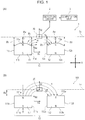
- Fig. 1(A) schematically illustrates the structure of a position detection device 1 according to a first embodiment of the present invention.
- the position detection device 1 includes a movement unit 10.
- the movement unit 10 is provided with a movement unit (not illustrated) that linearly reciprocates in the X direction, and a first magnet 11 and a second magnet 12 are mounted on the movement unit.
- the position detection device 1 is provided with a detection unit 20, and the movement unit 10 and the detection unit 20 face each other in the Z direction.
- the position detection device 1 may have a structure in which the first magnet 11 and the second magnet 12 stop, whereas the detection unit 20 moves. In this case, the relative movement trajectory of the magnets 11 and 12 and the detection unit 20 is also Tx.
- the detection unit 20 faces the middle of the first magnet 11 and the second magnet 12 in the X direction, and the first magnet 11 and the second magnet 12 move to the right or left in the X direction from a neutral position illustrated in Fig. 1(A) .
- the movement unit of the movement unit 10 may be urged leftward in the X direction by an urging member such as a compression coil spring and stop at an initial position.
- an urging member such as a compression coil spring and stop at an initial position.
- the first magnet 11 has a facing surface 11a that faces the movement trajectory Tx, a rear surface 11b opposite the facing surface 11a, and both side surfaces 11c and 11d that are oriented in the X direction.
- the facing surface 11a is part of a cylindrical surface having a curvature in the X direction.
- An opposing distance between the center of the facing surface 11a in the X direction and the movement trajectory Tx is indicated by ⁇ a.
- an opposing distance between an end of the facing surface 11a on the side surface 11c side and the movement trajectory Tx is indicated by ⁇ c
- an opposing distance between an end of the facing surface 11a on the side surface 11d side and the movement trajectory Tx is indicated by ⁇ d.
- the facing surface 11a has a shape such that both ends thereof in the X direction extending along the movement trajectory Tx are positioned farther away from the movement trajectory Tx than a center portion thereof.
- the rear surface 11b of the first magnet 11 is a flat surface that is parallel to the movement trajectory Tx and that is perpendicular to the plane of Fig. 1(A) .
- the side surface 11c and the side surface 11d are flat surfaces that are perpendicular to the movement trajectory Tx and that is perpendicular to the plane of Fig. 1(A) .
- the first magnet 11 is magnetized in the Z direction, which is a direction perpendicular to the movement trajectory Tx, and the facing surface 11a and the rear surface 11b are magnetized surfaces having opposite polarities.
- the facing surface 11a is magnetized to the N pole, and the rear surface 11b is magnetized to the S pole.
- the first magnet 11 and the second magnet 12 have the same size and shape.
- the second magnet 12 also has a facing surface 12a, a rear surface 12b, and side surfaces 12c and 12d.
- the shapes and dimensions of the respective surfaces are the same as those of the first magnet 11.
- the opposing distances ⁇ a, ⁇ c, and ⁇ d between the facing surface 12a and the movement trajectory Tx are also the same as those of the first magnet 11.
- the second magnet 12 is also magnetized in the Z direction, and the facing surface 12a and the rear surface 12b are magnetized surfaces. It is to be noted that the direction of magnetization of the second magnet 12 is reversed to the direction of magnetization of the first magnet 11 by 180 degrees, that is, the facing surface 12a is magnetized to the S pole and the rear surface 12b is magnetized to the N pole.
- the detection unit 20 has at least two magnetic sensors.
- a first magnetic sensor has an axis of sensitivity Sx directed parallel to the movement trajectory Tx and is capable of detecting a magnetic flux density in a direction parallel to the movement trajectory Tx.
- a second magnetic sensor has an axis of sensitivity Sz directed perpendicular to the movement trajectory Tx and is capable of detecting a magnetic flux density in a direction perpendicular to the movement trajectory Tx.
- the magnetic sensors are each constituted by a Hall element, a magnetoresistance effect element, or the like.
- the outputs from the first magnetic sensor and the second magnetic sensor of the detection unit 20 are detected by a detection circuit 2, and each output is subjected to A/D conversion and is provided to a computation unit 3.
- the computation unit 3 is constituted by a CPU, a memory, and so on.
- Fig. 1(B) illustrates a conventional position detection device 101 for comparison and describing the detection operation of the position detection device 1 according to the present invention.
- the position detection device 101 includes a first magnet 111 and a second 112, each of which has a cubic shape, with a facing surface 111a and a facing surface 112a being both flat surfaces that are parallel to the movement trajectory Tx and that are vertical to the plane of Fig. 1(B) .
- a rear surface 111b and a rear surface 112b are flat surfaces that are parallel to the facing surface 111a and the facing surface 112.
- Both the first magnet 111 and the second magnet 112 are magnetized in the Z direction.
- the facing surface 111a of the first magnet 111 is magnetized to the N pole
- the facing surface 112a of the second magnet 112 is magnetized to the S pole.
- An opposing distance ⁇ a between the facing surfaces 111a and 112a and the movement trajectory Tx is the same as the opposing distance ⁇ a at the center portions of the facing surfaces 11a and 12a of the magnets 11 and 12 illustrated in Fig. 1(A) .
- a magnetic field H extending from the facing surface 11a of the first magnet 11 to the facing surface 12a of the second magnet 12 is formed.
- a magnetic field H extending from the facing surface 111a of the first magnet 111 to the facing surface 112a of the second magnet 112 is formed.
- magnetic lines of force that generate the magnetic field H are indicated by broken lines.
- the detection output of the first magnetic sensor having the axis of sensitivity Sx and the detection output of the second magnetic sensor having the axis of sensitivity Sz, which are included in the detection unit 20, exhibit waveforms that are similar to a sine curve and a cosine curve.
- the computation unit 3 computes an arc tangent from changing outputs that are similar to a sine curve and a cosine curve. The computed value of the arc tangent changes substantially linearly, which enables the measurement of the relative movement positions of the movement unit 10 and the detection unit 20.
- each magnet is subjected to demagnetization in which a generated magnetic field decreases when the temperature of the magnet becomes high.
- the present invention has been made focusing on a difference between demagnetizing factors for a component (Bx) and a component (Bz) of the magnetic flux density of a magnetic field emerging from a magnet, which occurs when the temperature of the magnet becomes high, with the component (Bx) being directed in the X direction and the component (Bz) being directed in the Z direction.
- the difference between the demagnetizing factor for the component (Bx) and the demagnetizing factor for the component (Bz) at a high temperature gradually increases toward either end of each of the facing surfaces 111a and 1112a in the X direction from the center portions thereof.
- the facing surfaces 11a and 12a of the magnets 11 and 12 each have a shape such that the opposing distances ⁇ c and ⁇ d between both ends thereof in the X direction and the movement trajectory Tx are longer than the opposing distance ⁇ a between the center portion thereof and the movement trajectory Tx.
- the opposing distance ⁇ d between the facing surface 11a and the movement trajectory Tx becomes large.
- the sensitivity of the component (Bz) of the magnetic flux density in the Z direction, which is detected by the detection unit 20 becomes lower than that when the detection unit 20 faces the center of the facing surface 11a.
- the rate of decrease of the component (Bz) is greater than the rate of decrease of the sensitivity of the component (Bx) of the magnetic flux density in the X direction when the detection unit 20 faces the front of the side surface 11d.
- the facing surface 11a is an inclined curved surface that gradually inclines away from the movement trajectory Tx toward the side surface 11d from the center portion thereof.
- the magnetic field H directed from the facing surface 11a of the first magnet 11 to the facing surface 12a of the second magnet 12 tends to be inclined in the X direction toward the right end of the facing surface 11a.
- This also makes the rate of decrease of the sensitivity of the component (Bz) of the magnetic flux density in the Z direction greater than the rate of decrease of the sensitivity of the component (Bx) in the X direction when the detection unit 20 faces the front of the side surface 11d.
- the component (Bx) of the magnetic flux density in the X direction in front of the side surface 11d attenuates, the component (Bz) of the magnetic flux density in the Z direction, which is detected by the detection unit 20, can be decreased accordingly in accordance with the shape of the facing surface 11a.
- the calculated value of the arc tangent which is computed on the basis of the ratio of the detection output of the first magnetic sensor having the axis of sensitivity Sx and the detection output of the second magnetic sensor having the axis of sensitivity Sz, which are detected by the detection unit 20, can maintain linearity when the detection unit 20 faces the center portion of each of the facing surfaces 11a and 12a in the X direction and when the detection unit 20 faces either end of each of the facing surfaces 11a and 12a in the X direction.
- each of the facing surfaces 11a and 12a of the magnets 11 and 12 need to be gradually inclined such that both ends thereof in the X direction are farther away from the movement trajectory Tx than the center portions thereof.
- each of the facing surfaces 11a and 12a is formed to be a projecting curved surface, which allows the rate of attenuation of the component (Bx) of the magnetic flux density in the X direction that attenuates in a high-temperature environment to easily match the rate of attenuation of the component (Bz) in the Z direction toward either end thereof.
- Fig. 2 illustrates a position detection device 1A according to a second embodiment of the present invention.
- a first magnet 11 and a second magnet 12 that are used in the position detection device 1A are the same as those in the position detection device 1 illustrated in Fig. 1(A) .
- a movement unit 10 having the magnets 11 and 12 rotates, and a relative movement trajectory Tx of the movement unit 10 and a detection unit 20 extends along an arc of a circle.
- the magnets 11 and 12 may be fixed and the detection unit 20 may move along the arc-shaped movement trajectory Tx.
- the opposing distances ⁇ c and ⁇ d between both ends of each of the respective facing surfaces 11a and 12a of the magnets 11 and 12 along the arc-shaped movement trajectory and the movement trajectory Tx are longer than the opposing distance ⁇ a between the center portion thereof and the movement trajectory Tx.
- the difference in the rate of decrease between the detection output in a direction extending along the movement trajectory Tx and the detection output in a direction perpendicular to the movement trajectory Tx can be reduced and linearity can be maintained.
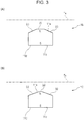
- FIG. 3(A) illustrates a position detection device 1B according to a third embodiment of the present invention.
- a magnet 11B used in the position detection device 1B has a facing surface 11a that is constituted by a flat portion (i) in a center portion thereof, which is parallel to the movement trajectory Tx, and inclined flat portions (ii) on both sides of the flat portion (i).
- FIG. 3(B) illustrates a position detection device 1C according to a fourth embodiment of the present invention.
- a magnet 11C used in the position detection device 1C has a facing surface 11a that is constituted by a projecting curved surface portion (iii) in a center portion thereof and inclined flat portions (ii) on both sides of the projecting curved surface portion (iii).
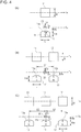
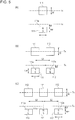
- a position detection device may include only one magnet, as illustrated in Fig. 4(A) , or three or more magnets, as illustrated in Fig. 4(C) .
- Fig. 4(A) illustrates Example 1, in which a single magnet 11 faces the relative movement trajectory Tx of the detection unit 20.
- Fig. 4(B) illustrates Example 2, in which two magnets 11 and 12 face the relative movement trajectory Tx of the detection unit 20.
- Fig. 4(C) illustrates Example 3, in which three magnets 11, 12, and 13 face the relative movement trajectory Tx of the detection unit 20.
- the magnets 11, 12, and 13 have facing surfaces 11a, 12a, and 13a that are projecting curved surfaces having curvatures in a direction extending along the movement trajectory Tx, with their radii of curvature being indicated by R.
- Fig. 5(A) illustrates Comparative Example 1, in which a single magnet 111 faces the relative movement trajectory Tx of the detection unit 20.
- Fig. 5(B) illustrates Comparative Example 2, in which two magnets 111 and 112 face the relative movement trajectory Tx of the detection unit 20.
- Fig. 5(C) illustrates Comparative Example 3, in which three magnets 111, 112, and 113 face the relative movement trajectory Tx of the detection unit 20.
- the magnets 111, 112, and 113 have facing surfaces 111a, 112a, and 113a that are all flat surfaces.
- the magnets 11, 12, and 13 in Examples and the magnets 111, 112, and 113 in Comparative Examples are each a rare-earth based (Nd-Fe-B based) injection molded magnet.
- the magnets 11, 12, and 13 in Examples and the magnets 111, 112, and 113 in Comparative Examples each have dimensions such that a height Hm is 6 mm, a length L in a direction extending along the movement trajectory Tx is 9 mm, and a width W in a direction perpendicular to the movement trajectory Tx is 9 mm.
- the facing surfaces 11a, 12a, and 13a of the magnets 11, 12, and 13 have a radius of curvature R of 9 mm.
- the opposing distance ⁇ a between the center portions of the facing surfaces of the magnets 11, 12, and 13 in Examples and the movement trajectory Tx and the opposing distance ⁇ a between the respective facing surfaces of the magnets 111, 112, and 113 in Comparative Examples and the movement trajectory Tx, that is, the shortest value of the opposing distance between each magnet and the movement trajectory Tx, are each 3.55 mm.
- an inter-magnet distance S1 is 17 mm
- an inter-magnet distance S2 is 18 mm.
- Figs. 6(A), 6(B), and 6(C) illustrate the moving position of the detection unit 20 and the linearity error for outputs of the detection unit 20 in the respective Examples.
- Figs. 7(A), 7(B), and 7(C) illustrate the moving position of the detection unit 20 and the linearity error for outputs of the detection unit 20 in the respective Comparative Examples.
- the horizontal axis represents the relative positions of each magnet and the detection unit 20 along the movement trajectory Tx.
- Fig. 6(A) illustrates simulation results of Example 1, and the origin "0" of the horizontal axis indicates that, as illustrated in Fig. 4(A) , the detection unit 20 is positioned to face the center of the magnet 11.
- Fig. 6(B) illustrates measurement results of Example 2
- the origin "0" of the horizontal axis indicates that, as illustrated in Fig. 4(B)
- the detection unit 20 is positioned in the middle of the two magnets 11 and 12.
- Fig. 6(C) illustrates measurement results of Example 3 and the origin "0" of the horizontal axis indicates that, as illustrated in Fig. 4(C) , the detection unit 20 is positioned to face the center of the middle magnet 11.
- Fig. 7(A) illustrates measurement results of Comparative Example 1, and the origin "0" of the horizontal axis indicates that, as illustrated in Fig. 5(A) , the detection unit 20 is positioned to face the center of the magnet 111.
- Fig. 7(B) illustrates measurement results of Comparative Example 2
- the origin "0" of the horizontal axis indicates that, as illustrated in Fig. 5(B) , the detection unit 20 is positioned in the middle of the two magnets 111 and 112.
- Fig. 7(C) illustrates measurement results of Comparative Example 3
- the origin "0" of the horizontal axis indicates that, as illustrated in Fig. 5(C) , the detection unit 20 is positioned to face the center of the middle magnet 111.
- Figs. 6(A), 6(B), and 6(C) and Figs. 7(A), 7(B), and 7(C) the characteristics at an environmental temperature of 150 °C are indicated by solid lines, and the characteristics at an environmental temperature of -40 °C are indicated by broken lines.
- the vertical axis represents an error of the calculated value of the arc tangent (ATAN) computed on the basis of the detection output of the first magnetic sensor having the axis of sensitivity Sx and the detection output of the second magnetic sensor having the axis of sensitivity Sz, which are included in the detection unit 20.
- ATAN arc tangent
- the difference (deg) between the calculated value of the arc tangent (ATAN) at a room temperature of 20 °C and the calculated value of the arc tangent (ATAN) at 150 °C is indicated by a solid line
- the difference (deg) between the calculated value of the arc tangent (ATAN) at a room temperature of 20 °C and the calculated value of the arc tangent (ATAN) at -40 °C is indicated by a broken line.
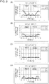
- Fig. 8 illustrates simulation results for Examples 2A, 2B, 2C, and 2D, which are modifications of Example 2 illustrated in Fig. 4(B) .
- Each magnet has a facing surface with its radius of curvature R being 4.5 mm in Example 2A in Fig. 8(A) , being 6.0 mm in Example 2B in Fig. 8(B) , being 9.0 mm in Example 2C in Fig. (C), and being 12 mm in Example 2D in Fig. 8(D) .
Landscapes
- Physics & Mathematics (AREA)
- General Physics & Mathematics (AREA)
- Condensed Matter Physics & Semiconductors (AREA)
- Transmission And Conversion Of Sensor Element Output (AREA)
- Measurement Of Length, Angles, Or The Like Using Electric Or Magnetic Means (AREA)
Claims (5)
- Dispositif de détection d'une position (1) comprenant une unité de détection (20) et un aimant (11, 12) qui est disposé à l'opposé de l'unité de détection (20), l'unité de détection (20) et l'aimant (11, 12) étant mobiles l'un par rapport à l'autre ;
dans lequel l'aimant (11, 12) est magnétisé dans une direction qui est perpendiculaire à une trajectoire de mouvement relatif (Tx) de l'unité de détection (20), et l'unité de détection (20) englobe un capteur magnétique qui détecte une composante d'un flux magnétique émanant de l'aimant (11, 12), qui est parallèle à la trajectoire de mouvement (Tx), et un capteur magnétique qui détecte une composante du flux magnétique, qui est perpendiculaire à la trajectoire de mouvement (Tx) ; et
dans lequel l'aimant (11, 12) possède une surface orientée (11a, 12a), orientée sur la trajectoire de mouvement (Tx) ; et, lorsqu'on regarde dans une vue en coupe transversale qui comprend la trajectoire de mouvement (Tx), une distance entre la trajectoire de mouvement (Tx) et chacune des deux extrémités de la surface orientée (11a, 12a) dans une direction qui s'étend le long de la trajectoire de mouvement (Tx) est plus longue qu'une distance qui s'étend entre la trajectoire de mouvement (Tx) et une portion centrale de la surface orientée (11a, 12a) ;
caractérisé en ce que
un certain nombre des aimants (11, 12) sont disposés le long de la trajectoire de mouvement (Tx) et les surfaces orientées (11a, 12a) d'aimants adjacents (11, 12) parmi les aimants (11, 12) sont magnétisées à des polarités opposées. - Dispositif de détection d'une position selon la revendication 1, dans lequel, lorsqu'on regarde dans une vue en coupe transversale qui comprend la trajectoire de mouvement (Tx), la surface orientée représente une surface courbe faisant saillie dont la courbure se dessine dans une direction qui s'étend le long de la trajectoire de mouvement (Tx).
- Dispositif de détection d'une position selon la revendication 2, dans lequel la courbure possède un rayon qui est supérieur ou égal à 1,7 fois et qui est inférieur ou égal à 3,4 fois une distance la plus courte s'étendant entre la surface orientée et la trajectoire de mouvement (Tx).
- Dispositif de détection d'une position selon l'une quelconque des revendications 1 à 3, dans lequel la trajectoire de mouvement (Tx) est une ligne droite.
- Dispositif de détection d'une position selon l'une quelconque des revendications 1 à 3, dans lequel la trajectoire de mouvement (Tx) est un arc de cercle.
Applications Claiming Priority (2)
| Application Number | Priority Date | Filing Date | Title |
|---|---|---|---|
| JP2015211556 | 2015-10-28 | ||
| PCT/JP2016/074941 WO2017073151A1 (fr) | 2015-10-28 | 2016-08-26 | Dispositif de détection de position |
Publications (3)
| Publication Number | Publication Date |
|---|---|
| EP3370038A1 EP3370038A1 (fr) | 2018-09-05 |
| EP3370038A4 EP3370038A4 (fr) | 2019-06-12 |
| EP3370038B1 true EP3370038B1 (fr) | 2020-06-17 |
Family
ID=58630325
Family Applications (1)
| Application Number | Title | Priority Date | Filing Date |
|---|---|---|---|
| EP16859388.7A Active EP3370038B1 (fr) | 2015-10-28 | 2016-08-26 | Dispositif de détection de position |
Country Status (6)
| Country | Link |
|---|---|
| US (1) | US20180216925A1 (fr) |
| EP (1) | EP3370038B1 (fr) |
| JP (1) | JP6492193B2 (fr) |
| KR (1) | KR102042369B1 (fr) |
| CN (1) | CN108351222B (fr) |
| WO (1) | WO2017073151A1 (fr) |
Families Citing this family (30)
| Publication number | Priority date | Publication date | Assignee | Title |
|---|---|---|---|---|
| CN105308947B (zh) | 2013-06-13 | 2018-10-02 | 核心光电有限公司 | 双孔径变焦数字摄影机 |
| CN105359006B (zh) | 2013-07-04 | 2018-06-22 | 核心光电有限公司 | 小型长焦透镜套件 |
| EP3028443A2 (fr) | 2013-08-01 | 2016-06-08 | Corephotonics Ltd. | Système d'imagerie à ouverture multiple mince doté d'une mise au point automatique et ses procédés d'utilisation |
| US9392188B2 (en) | 2014-08-10 | 2016-07-12 | Corephotonics Ltd. | Zoom dual-aperture camera with folded lens |
| WO2016108093A1 (fr) | 2015-01-03 | 2016-07-07 | Corephotonics Ltd. | Module de lentille de téléobjectif miniature et appareil photographique utilisant un tel module de lentille |
| KR102078978B1 (ko) | 2015-04-16 | 2020-02-19 | 코어포토닉스 리미티드 | 소형 접이식 카메라의 오토 포커스 및 광학 이미지 안정화 |
| WO2017025822A1 (fr) | 2015-08-13 | 2017-02-16 | Corephotonics Ltd. | Appareil de prise de vues à focale variable à double ouverture ayant un support et une commande dynamique de commutation/non commutation |
| EP3758356B1 (fr) | 2016-05-30 | 2021-10-20 | Corephotonics Ltd. | Actionneur |
| KR102657464B1 (ko) | 2016-07-07 | 2024-04-12 | 코어포토닉스 리미티드 | 폴디드 옵틱용 선형 볼 가이드 보이스 코일 모터 |
| US11531209B2 (en) | 2016-12-28 | 2022-12-20 | Corephotonics Ltd. | Folded camera structure with an extended light-folding-element scanning range |
| EP4145206A1 (fr) | 2017-01-12 | 2023-03-08 | Corephotonics Ltd. | Caméra compacte pliée |
| WO2019049414A1 (fr) * | 2017-09-07 | 2019-03-14 | 株式会社村田製作所 | Capteur magnétique et capteur de courant comprenant ce dernier |
| JP6806919B2 (ja) | 2017-11-23 | 2021-01-06 | コアフォトニクス リミテッド | コンパクト屈曲式カメラ構造 |
| JP6954139B2 (ja) * | 2018-01-16 | 2021-10-27 | 株式会社デンソー | 回転角度検出装置 |
| KR102781658B1 (ko) | 2018-04-23 | 2025-03-13 | 코어포토닉스 리미티드 | 연장된 2 자유도 회전 범위를 갖는 광학 경로 폴딩 요소 |
| US11287081B2 (en) | 2019-01-07 | 2022-03-29 | Corephotonics Ltd. | Rotation mechanism with sliding joint |
| CN121284176A (zh) | 2019-07-31 | 2026-01-06 | 核心光电有限公司 | 在相机摇摄或运动中创建背景模糊的系统 |
| EP4509897A3 (fr) | 2019-12-03 | 2025-05-14 | Corephotonics Ltd. | Actionneurs pour fournir une plage de rotation étendue à deux degrés de liberté |
| US11949976B2 (en) | 2019-12-09 | 2024-04-02 | Corephotonics Ltd. | Systems and methods for obtaining a smart panoramic image |
| US12007668B2 (en) | 2020-02-22 | 2024-06-11 | Corephotonics Ltd. | Split screen feature for macro photography |
| JP6824484B1 (ja) * | 2020-03-10 | 2021-02-03 | 三菱電機株式会社 | 磁気式リニア位置検出器 |
| WO2021234515A1 (fr) | 2020-05-17 | 2021-11-25 | Corephotonics Ltd. | Assemblage d'images en présence d'une image de référence à champ de vision complet |
| CN117572549A (zh) | 2020-05-30 | 2024-02-20 | 核心光电有限公司 | 用于获得超微距图像的系统和方法 |
| US11637977B2 (en) | 2020-07-15 | 2023-04-25 | Corephotonics Ltd. | Image sensors and sensing methods to obtain time-of-flight and phase detection information |
| EP4045960B1 (fr) | 2020-07-15 | 2024-12-04 | Corephotonics Ltd. | Correction d'aberrations de point de vue dans un appareil photographique à balayage, à système à trajet optique replié |
| CN114270145B (zh) * | 2020-07-31 | 2024-05-17 | 核心光电有限公司 | 用于大行程线性位置感测的霍尔传感器-磁体几何结构 |
| CN116626960A (zh) | 2020-08-12 | 2023-08-22 | 核心光电有限公司 | 用于光学防抖的方法 |
| KR20250165686A (ko) | 2021-03-11 | 2025-11-26 | 코어포토닉스 리미티드 | 팝-아웃 카메라 시스템 |
| JP7507729B2 (ja) | 2021-06-21 | 2024-06-28 | Tdk株式会社 | 磁気センサと磁気センサを用いたブレーキシステム及びステアリングシステム |
| KR20250028500A (ko) | 2022-03-24 | 2025-02-28 | 코어포토닉스 리미티드 | 슬림 컴팩트 렌즈 광학 이미지 안정화 |
Family Cites Families (14)
| Publication number | Priority date | Publication date | Assignee | Title |
|---|---|---|---|---|
| US708895A (en) * | 1901-11-27 | 1902-09-09 | William J Martin | Furniture-caster. |
| JP3191531B2 (ja) | 1993-10-20 | 2001-07-23 | ミノルタ株式会社 | 画像形成装置 |
| JP3419533B2 (ja) * | 1994-03-07 | 2003-06-23 | 帝人製機株式会社 | 磁気スケールおよびこれを備えた磁気式検出装置 |
| JP3597733B2 (ja) * | 1999-08-09 | 2004-12-08 | アルプス電気株式会社 | 磁気式変位検出装置 |
| US6577123B2 (en) * | 2001-06-04 | 2003-06-10 | Delphi Technologies, Inc. | Linear position sensor assembly |
| US6653830B2 (en) * | 2001-12-14 | 2003-11-25 | Wabash Technologies, Inc. | Magnetic position sensor having shaped pole pieces to provide a magnetic field having a varying magnetic flux density field strength |
| DE10202320A1 (de) * | 2002-01-23 | 2003-07-31 | Bosch Gmbh Robert | Wegsensor mit magnetoelektrischem Wandlerelement |
| DE10334869B3 (de) * | 2003-07-29 | 2004-09-16 | Tech3 E.K. | Drehwinkelsensor |
| US7088095B1 (en) * | 2004-02-04 | 2006-08-08 | Honeywell International Inc. | Balanced magnetic linear displacement sensor |
| JP4787601B2 (ja) * | 2005-11-08 | 2011-10-05 | 株式会社東海理化電機製作所 | 位置検出装置 |
| DE112009000299A5 (de) * | 2008-04-02 | 2011-03-03 | Polycontact Ag | Magnetische Linearsensoranordnung |
| JP4985730B2 (ja) * | 2009-01-29 | 2012-07-25 | 株式会社デンソー | ストロークセンサおよび回転角センサ |
| JP5408508B2 (ja) * | 2011-11-01 | 2014-02-05 | 株式会社デンソー | 位置検出装置 |
| CN203178236U (zh) * | 2013-02-07 | 2013-09-04 | 中国石油天然气股份有限公司 | 一种新型漏磁检测传感器 |
-
2016
- 2016-08-26 JP JP2017547653A patent/JP6492193B2/ja active Active
- 2016-08-26 EP EP16859388.7A patent/EP3370038B1/fr active Active
- 2016-08-26 WO PCT/JP2016/074941 patent/WO2017073151A1/fr not_active Ceased
- 2016-08-26 KR KR1020187011042A patent/KR102042369B1/ko active Active
- 2016-08-26 CN CN201680061505.6A patent/CN108351222B/zh active Active
-
2018
- 2018-03-29 US US15/939,418 patent/US20180216925A1/en not_active Abandoned
Non-Patent Citations (1)
| Title |
|---|
| None * |
Also Published As
| Publication number | Publication date |
|---|---|
| EP3370038A4 (fr) | 2019-06-12 |
| KR102042369B1 (ko) | 2019-11-07 |
| US20180216925A1 (en) | 2018-08-02 |
| CN108351222A (zh) | 2018-07-31 |
| JPWO2017073151A1 (ja) | 2018-07-26 |
| CN108351222B (zh) | 2020-10-30 |
| JP6492193B2 (ja) | 2019-03-27 |
| EP3370038A1 (fr) | 2018-09-05 |
| WO2017073151A1 (fr) | 2017-05-04 |
| KR20180056712A (ko) | 2018-05-29 |
Similar Documents
| Publication | Publication Date | Title |
|---|---|---|
| EP3370038A1 (fr) | Dispositif de détection de position | |
| JP5079816B2 (ja) | 好ましくは擬似正弦的に変化する磁石外形を有する磁気式位置センサ | |
| US9618318B2 (en) | Method for contactlessly measuring a relative position by means of a 3D hall sensor having measurement signal store | |
| US7977935B2 (en) | Temperature tolerant magnetic linear displacement sensor | |
| US20060066297A1 (en) | Magnetic position sensor | |
| US20130063132A1 (en) | Linear position sensor | |
| US20030094941A1 (en) | Displacement sensor | |
| CN101328915A (zh) | 调整元件 | |
| EP2657651A3 (fr) | Capteur de position | |
| US8829896B2 (en) | Stroke amount detecting device | |
| JP5500389B2 (ja) | ストローク量検出装置 | |
| US9562791B2 (en) | Measurement system of the relative position between two separate structural parts | |
| JP2017049127A (ja) | 磁場検出装置及び回転検出装置 | |
| CN106461418A (zh) | 磁式位置检测装置 | |
| JP5958294B2 (ja) | ストロークセンサ | |
| US9068817B2 (en) | Location detector device | |
| JP4787601B2 (ja) | 位置検出装置 | |
| US9638547B2 (en) | Selective slope linear position sensor | |
| CN105674865A (zh) | 行程传感器 | |
| JP3191530U (ja) | 位置検出装置 | |
| WO2023058356A1 (fr) | Dispositif de détection de position | |
| JP2016212070A (ja) | 移動物体検出装置 | |
| JP2014098654A (ja) | ストロークセンサ | |
| JP2016151486A (ja) | 距離測定装置 | |
| JP2017111048A (ja) | 位置センサ |
Legal Events
| Date | Code | Title | Description |
|---|---|---|---|
| STAA | Information on the status of an ep patent application or granted ep patent |
Free format text: STATUS: THE INTERNATIONAL PUBLICATION HAS BEEN MADE |
|
| PUAI | Public reference made under article 153(3) epc to a published international application that has entered the european phase |
Free format text: ORIGINAL CODE: 0009012 |
|
| STAA | Information on the status of an ep patent application or granted ep patent |
Free format text: STATUS: REQUEST FOR EXAMINATION WAS MADE |
|
| 17P | Request for examination filed |
Effective date: 20180329 |
|
| AK | Designated contracting states |
Kind code of ref document: A1 Designated state(s): AL AT BE BG CH CY CZ DE DK EE ES FI FR GB GR HR HU IE IS IT LI LT LU LV MC MK MT NL NO PL PT RO RS SE SI SK SM TR |
|
| AX | Request for extension of the european patent |
Extension state: BA ME |
|
| DAV | Request for validation of the european patent (deleted) | ||
| DAX | Request for extension of the european patent (deleted) | ||
| RAP1 | Party data changed (applicant data changed or rights of an application transferred) |
Owner name: ALPS ALPINE CO., LTD. |
|
| REG | Reference to a national code |
Ref country code: DE Ref legal event code: R079 Ref document number: 602016038481 Country of ref document: DE Free format text: PREVIOUS MAIN CLASS: G01D0005140000 Ipc: G01D0003036000 |
|
| A4 | Supplementary search report drawn up and despatched |
Effective date: 20190510 |
|
| RIC1 | Information provided on ipc code assigned before grant |
Ipc: G01B 5/00 20060101ALI20190506BHEP Ipc: G01D 3/036 20060101AFI20190506BHEP Ipc: G01R 33/09 20060101ALI20190506BHEP Ipc: G01D 5/18 20060101ALI20190506BHEP Ipc: G01D 5/14 20060101ALI20190506BHEP Ipc: G01R 33/02 20060101ALI20190506BHEP Ipc: G01B 7/00 20060101ALI20190506BHEP |
|
| GRAP | Despatch of communication of intention to grant a patent |
Free format text: ORIGINAL CODE: EPIDOSNIGR1 |
|
| STAA | Information on the status of an ep patent application or granted ep patent |
Free format text: STATUS: GRANT OF PATENT IS INTENDED |
|
| INTG | Intention to grant announced |
Effective date: 20200116 |
|
| GRAS | Grant fee paid |
Free format text: ORIGINAL CODE: EPIDOSNIGR3 |
|
| GRAA | (expected) grant |
Free format text: ORIGINAL CODE: 0009210 |
|
| STAA | Information on the status of an ep patent application or granted ep patent |
Free format text: STATUS: THE PATENT HAS BEEN GRANTED |
|
| AK | Designated contracting states |
Kind code of ref document: B1 Designated state(s): AL AT BE BG CH CY CZ DE DK EE ES FI FR GB GR HR HU IE IS IT LI LT LU LV MC MK MT NL NO PL PT RO RS SE SI SK SM TR |
|
| REG | Reference to a national code |
Ref country code: GB Ref legal event code: FG4D |
|
| REG | Reference to a national code |
Ref country code: CH Ref legal event code: EP |
|
| REG | Reference to a national code |
Ref country code: IE Ref legal event code: FG4D |
|
| REG | Reference to a national code |
Ref country code: DE Ref legal event code: R096 Ref document number: 602016038481 Country of ref document: DE |
|
| REG | Reference to a national code |
Ref country code: AT Ref legal event code: REF Ref document number: 1281852 Country of ref document: AT Kind code of ref document: T Effective date: 20200715 |
|
| PG25 | Lapsed in a contracting state [announced via postgrant information from national office to epo] |
Ref country code: LT Free format text: LAPSE BECAUSE OF FAILURE TO SUBMIT A TRANSLATION OF THE DESCRIPTION OR TO PAY THE FEE WITHIN THE PRESCRIBED TIME-LIMIT Effective date: 20200617 Ref country code: SE Free format text: LAPSE BECAUSE OF FAILURE TO SUBMIT A TRANSLATION OF THE DESCRIPTION OR TO PAY THE FEE WITHIN THE PRESCRIBED TIME-LIMIT Effective date: 20200617 Ref country code: NO Free format text: LAPSE BECAUSE OF FAILURE TO SUBMIT A TRANSLATION OF THE DESCRIPTION OR TO PAY THE FEE WITHIN THE PRESCRIBED TIME-LIMIT Effective date: 20200917 Ref country code: GR Free format text: LAPSE BECAUSE OF FAILURE TO SUBMIT A TRANSLATION OF THE DESCRIPTION OR TO PAY THE FEE WITHIN THE PRESCRIBED TIME-LIMIT Effective date: 20200918 Ref country code: FI Free format text: LAPSE BECAUSE OF FAILURE TO SUBMIT A TRANSLATION OF THE DESCRIPTION OR TO PAY THE FEE WITHIN THE PRESCRIBED TIME-LIMIT Effective date: 20200617 |
|
| PGFP | Annual fee paid to national office [announced via postgrant information from national office to epo] |
Ref country code: FR Payment date: 20200821 Year of fee payment: 5 |
|
| REG | Reference to a national code |
Ref country code: LT Ref legal event code: MG4D |
|
| REG | Reference to a national code |
Ref country code: NL Ref legal event code: MP Effective date: 20200617 |
|
| PG25 | Lapsed in a contracting state [announced via postgrant information from national office to epo] |
Ref country code: LV Free format text: LAPSE BECAUSE OF FAILURE TO SUBMIT A TRANSLATION OF THE DESCRIPTION OR TO PAY THE FEE WITHIN THE PRESCRIBED TIME-LIMIT Effective date: 20200617 Ref country code: HR Free format text: LAPSE BECAUSE OF FAILURE TO SUBMIT A TRANSLATION OF THE DESCRIPTION OR TO PAY THE FEE WITHIN THE PRESCRIBED TIME-LIMIT Effective date: 20200617 Ref country code: BG Free format text: LAPSE BECAUSE OF FAILURE TO SUBMIT A TRANSLATION OF THE DESCRIPTION OR TO PAY THE FEE WITHIN THE PRESCRIBED TIME-LIMIT Effective date: 20200917 Ref country code: RS Free format text: LAPSE BECAUSE OF FAILURE TO SUBMIT A TRANSLATION OF THE DESCRIPTION OR TO PAY THE FEE WITHIN THE PRESCRIBED TIME-LIMIT Effective date: 20200617 |
|
| REG | Reference to a national code |
Ref country code: AT Ref legal event code: MK05 Ref document number: 1281852 Country of ref document: AT Kind code of ref document: T Effective date: 20200617 |
|
| PG25 | Lapsed in a contracting state [announced via postgrant information from national office to epo] |
Ref country code: NL Free format text: LAPSE BECAUSE OF FAILURE TO SUBMIT A TRANSLATION OF THE DESCRIPTION OR TO PAY THE FEE WITHIN THE PRESCRIBED TIME-LIMIT Effective date: 20200617 Ref country code: AL Free format text: LAPSE BECAUSE OF FAILURE TO SUBMIT A TRANSLATION OF THE DESCRIPTION OR TO PAY THE FEE WITHIN THE PRESCRIBED TIME-LIMIT Effective date: 20200617 |
|
| PG25 | Lapsed in a contracting state [announced via postgrant information from national office to epo] |
Ref country code: CZ Free format text: LAPSE BECAUSE OF FAILURE TO SUBMIT A TRANSLATION OF THE DESCRIPTION OR TO PAY THE FEE WITHIN THE PRESCRIBED TIME-LIMIT Effective date: 20200617 Ref country code: RO Free format text: LAPSE BECAUSE OF FAILURE TO SUBMIT A TRANSLATION OF THE DESCRIPTION OR TO PAY THE FEE WITHIN THE PRESCRIBED TIME-LIMIT Effective date: 20200617 Ref country code: ES Free format text: LAPSE BECAUSE OF FAILURE TO SUBMIT A TRANSLATION OF THE DESCRIPTION OR TO PAY THE FEE WITHIN THE PRESCRIBED TIME-LIMIT Effective date: 20200617 Ref country code: PT Free format text: LAPSE BECAUSE OF FAILURE TO SUBMIT A TRANSLATION OF THE DESCRIPTION OR TO PAY THE FEE WITHIN THE PRESCRIBED TIME-LIMIT Effective date: 20201019 Ref country code: IT Free format text: LAPSE BECAUSE OF FAILURE TO SUBMIT A TRANSLATION OF THE DESCRIPTION OR TO PAY THE FEE WITHIN THE PRESCRIBED TIME-LIMIT Effective date: 20200617 Ref country code: SM Free format text: LAPSE BECAUSE OF FAILURE TO SUBMIT A TRANSLATION OF THE DESCRIPTION OR TO PAY THE FEE WITHIN THE PRESCRIBED TIME-LIMIT Effective date: 20200617 Ref country code: AT Free format text: LAPSE BECAUSE OF FAILURE TO SUBMIT A TRANSLATION OF THE DESCRIPTION OR TO PAY THE FEE WITHIN THE PRESCRIBED TIME-LIMIT Effective date: 20200617 Ref country code: EE Free format text: LAPSE BECAUSE OF FAILURE TO SUBMIT A TRANSLATION OF THE DESCRIPTION OR TO PAY THE FEE WITHIN THE PRESCRIBED TIME-LIMIT Effective date: 20200617 |
|
| PG25 | Lapsed in a contracting state [announced via postgrant information from national office to epo] |
Ref country code: PL Free format text: LAPSE BECAUSE OF FAILURE TO SUBMIT A TRANSLATION OF THE DESCRIPTION OR TO PAY THE FEE WITHIN THE PRESCRIBED TIME-LIMIT Effective date: 20200617 Ref country code: SK Free format text: LAPSE BECAUSE OF FAILURE TO SUBMIT A TRANSLATION OF THE DESCRIPTION OR TO PAY THE FEE WITHIN THE PRESCRIBED TIME-LIMIT Effective date: 20200617 Ref country code: IS Free format text: LAPSE BECAUSE OF FAILURE TO SUBMIT A TRANSLATION OF THE DESCRIPTION OR TO PAY THE FEE WITHIN THE PRESCRIBED TIME-LIMIT Effective date: 20201017 |
|
| REG | Reference to a national code |
Ref country code: DE Ref legal event code: R097 Ref document number: 602016038481 Country of ref document: DE |
|
| PG25 | Lapsed in a contracting state [announced via postgrant information from national office to epo] |
Ref country code: MC Free format text: LAPSE BECAUSE OF FAILURE TO SUBMIT A TRANSLATION OF THE DESCRIPTION OR TO PAY THE FEE WITHIN THE PRESCRIBED TIME-LIMIT Effective date: 20200617 |
|
| REG | Reference to a national code |
Ref country code: CH Ref legal event code: PL |
|
| PLBE | No opposition filed within time limit |
Free format text: ORIGINAL CODE: 0009261 |
|
| STAA | Information on the status of an ep patent application or granted ep patent |
Free format text: STATUS: NO OPPOSITION FILED WITHIN TIME LIMIT |
|
| PG25 | Lapsed in a contracting state [announced via postgrant information from national office to epo] |
Ref country code: LU Free format text: LAPSE BECAUSE OF NON-PAYMENT OF DUE FEES Effective date: 20200826 Ref country code: DK Free format text: LAPSE BECAUSE OF FAILURE TO SUBMIT A TRANSLATION OF THE DESCRIPTION OR TO PAY THE FEE WITHIN THE PRESCRIBED TIME-LIMIT Effective date: 20200617 Ref country code: CH Free format text: LAPSE BECAUSE OF NON-PAYMENT OF DUE FEES Effective date: 20200831 Ref country code: LI Free format text: LAPSE BECAUSE OF NON-PAYMENT OF DUE FEES Effective date: 20200831 |
|
| 26N | No opposition filed |
Effective date: 20210318 |
|
| GBPC | Gb: european patent ceased through non-payment of renewal fee |
Effective date: 20200917 |
|
| REG | Reference to a national code |
Ref country code: BE Ref legal event code: MM Effective date: 20200831 |
|
| PG25 | Lapsed in a contracting state [announced via postgrant information from national office to epo] |
Ref country code: SI Free format text: LAPSE BECAUSE OF FAILURE TO SUBMIT A TRANSLATION OF THE DESCRIPTION OR TO PAY THE FEE WITHIN THE PRESCRIBED TIME-LIMIT Effective date: 20200617 |
|
| PG25 | Lapsed in a contracting state [announced via postgrant information from national office to epo] |
Ref country code: IE Free format text: LAPSE BECAUSE OF NON-PAYMENT OF DUE FEES Effective date: 20200826 Ref country code: GB Free format text: LAPSE BECAUSE OF NON-PAYMENT OF DUE FEES Effective date: 20200917 Ref country code: BE Free format text: LAPSE BECAUSE OF NON-PAYMENT OF DUE FEES Effective date: 20200831 |
|
| PG25 | Lapsed in a contracting state [announced via postgrant information from national office to epo] |
Ref country code: TR Free format text: LAPSE BECAUSE OF FAILURE TO SUBMIT A TRANSLATION OF THE DESCRIPTION OR TO PAY THE FEE WITHIN THE PRESCRIBED TIME-LIMIT Effective date: 20200617 Ref country code: MT Free format text: LAPSE BECAUSE OF FAILURE TO SUBMIT A TRANSLATION OF THE DESCRIPTION OR TO PAY THE FEE WITHIN THE PRESCRIBED TIME-LIMIT Effective date: 20200617 Ref country code: CY Free format text: LAPSE BECAUSE OF FAILURE TO SUBMIT A TRANSLATION OF THE DESCRIPTION OR TO PAY THE FEE WITHIN THE PRESCRIBED TIME-LIMIT Effective date: 20200617 |
|
| PG25 | Lapsed in a contracting state [announced via postgrant information from national office to epo] |
Ref country code: MK Free format text: LAPSE BECAUSE OF FAILURE TO SUBMIT A TRANSLATION OF THE DESCRIPTION OR TO PAY THE FEE WITHIN THE PRESCRIBED TIME-LIMIT Effective date: 20200617 |
|
| PG25 | Lapsed in a contracting state [announced via postgrant information from national office to epo] |
Ref country code: FR Free format text: LAPSE BECAUSE OF NON-PAYMENT OF DUE FEES Effective date: 20210831 |
|
| PGFP | Annual fee paid to national office [announced via postgrant information from national office to epo] |
Ref country code: DE Payment date: 20250820 Year of fee payment: 10 |