EP2820438B1 - Procédé et dispositif de mesure de courants ou de champs magnétiques au moyen de capteurs à effet hall - Google Patents
Procédé et dispositif de mesure de courants ou de champs magnétiques au moyen de capteurs à effet hall Download PDFInfo
- Publication number
- EP2820438B1 EP2820438B1 EP13707276.5A EP13707276A EP2820438B1 EP 2820438 B1 EP2820438 B1 EP 2820438B1 EP 13707276 A EP13707276 A EP 13707276A EP 2820438 B1 EP2820438 B1 EP 2820438B1
- Authority
- EP
- European Patent Office
- Prior art keywords
- spinning current
- offset
- samples
- time period
- spinning
- Prior art date
- Legal status (The legal status is an assumption and is not a legal conclusion. Google has not performed a legal analysis and makes no representation as to the accuracy of the status listed.)
- Active
Links
Images

Classifications
-
- G—PHYSICS
- G01—MEASURING; TESTING
- G01R—MEASURING ELECTRIC VARIABLES; MEASURING MAGNETIC VARIABLES
- G01R15/00—Details of measuring arrangements of the types provided for in groups G01R17/00 - G01R29/00, G01R33/00 - G01R33/26 or G01R35/00
- G01R15/14—Adaptations providing voltage or current isolation, e.g. for high-voltage or high-current networks
- G01R15/20—Adaptations providing voltage or current isolation, e.g. for high-voltage or high-current networks using galvano-magnetic devices, e.g. Hall-effect devices, i.e. measuring a magnetic field via the interaction between a current and a magnetic field, e.g. magneto resistive or Hall effect devices
- G01R15/202—Adaptations providing voltage or current isolation, e.g. for high-voltage or high-current networks using galvano-magnetic devices, e.g. Hall-effect devices, i.e. measuring a magnetic field via the interaction between a current and a magnetic field, e.g. magneto resistive or Hall effect devices using Hall-effect devices
-
- G—PHYSICS
- G01—MEASURING; TESTING
- G01D—MEASURING NOT SPECIALLY ADAPTED FOR A SPECIFIC VARIABLE; ARRANGEMENTS FOR MEASURING TWO OR MORE VARIABLES NOT COVERED IN A SINGLE OTHER SUBCLASS; TARIFF METERING APPARATUS; MEASURING OR TESTING NOT OTHERWISE PROVIDED FOR
- G01D5/00—Mechanical means for transferring the output of a sensing member; Means for converting the output of a sensing member to another variable where the form or nature of the sensing member does not constrain the means for converting; Transducers not specially adapted for a specific variable
- G01D5/12—Mechanical means for transferring the output of a sensing member; Means for converting the output of a sensing member to another variable where the form or nature of the sensing member does not constrain the means for converting; Transducers not specially adapted for a specific variable using electric or magnetic means
- G01D5/14—Mechanical means for transferring the output of a sensing member; Means for converting the output of a sensing member to another variable where the form or nature of the sensing member does not constrain the means for converting; Transducers not specially adapted for a specific variable using electric or magnetic means influencing the magnitude of a current or voltage
- G01D5/142—Mechanical means for transferring the output of a sensing member; Means for converting the output of a sensing member to another variable where the form or nature of the sensing member does not constrain the means for converting; Transducers not specially adapted for a specific variable using electric or magnetic means influencing the magnitude of a current or voltage using Hall-effect devices
-
- G—PHYSICS
- G01—MEASURING; TESTING
- G01R—MEASURING ELECTRIC VARIABLES; MEASURING MAGNETIC VARIABLES
- G01R33/00—Arrangements or instruments for measuring magnetic variables
- G01R33/0017—Means for compensating offset magnetic fields or the magnetic flux to be measured; Means for generating calibration magnetic fields
-
- G—PHYSICS
- G01—MEASURING; TESTING
- G01R—MEASURING ELECTRIC VARIABLES; MEASURING MAGNETIC VARIABLES
- G01R33/00—Arrangements or instruments for measuring magnetic variables
- G01R33/02—Measuring direction or magnitude of magnetic fields or magnetic flux
- G01R33/06—Measuring direction or magnitude of magnetic fields or magnetic flux using galvano-magnetic devices
- G01R33/07—Hall effect devices
-
- G—PHYSICS
- G01—MEASURING; TESTING
- G01R—MEASURING ELECTRIC VARIABLES; MEASURING MAGNETIC VARIABLES
- G01R33/00—Arrangements or instruments for measuring magnetic variables
- G01R33/02—Measuring direction or magnitude of magnetic fields or magnetic flux
- G01R33/06—Measuring direction or magnitude of magnetic fields or magnetic flux using galvano-magnetic devices
- G01R33/07—Hall effect devices
- G01R33/072—Constructional adaptation of the sensor to specific applications
- G01R33/075—Hall devices configured for spinning current measurements
Definitions
- the present invention relates to a method and a device for measuring currents or magnetic fields with at least one Hall sensor, which is operated in spinning current technology, wherein sensor signals of the Hall sensor with an analog-to-digital converter are converted into digital signals , the digital signals of the analog-to-digital converter are read out and combined for each spinning current phase over a first time period to obtain a first sample, and the first samples of the spinning current phases of a spinning current cycle for Forming a spinning current reading of the current or magnetic field are added.
- US 2009/009164 A1 discloses a method for measuring currents or magnetic fields with a Hall sensor, which is operated in spinning current technology, wherein sensor signals of the Hall sensor with an analog-to-digital converter converted into digital signals become.
- the main problem with current measurement with Hall sensors without a magnetic core is the relatively high sensor offset with respect to the signal hub.
- the so-called spinning current principle is implemented in almost every Hall sensor system. For each measurement, the operating current direction in the Hall element or Hall sensor and at the same time the connections for the signal output (Hall contacts) are switched one or more times. From the individual measurements in the different spinning current phases (usually two or four), a sum value is formed whose offset component is significantly lower than in the individual phases.
- the possible measuring frequency is limited by the transient effects when switching between the individual phases and by the necessary accuracy of the measured values.
- Hall sensor systems for current measurement with ⁇ modulators ( ⁇ M) for analog-to-digital conversion are ideally suited for this, if they are operated synchronously with the converter. In this case, full cycles of inverter clocking can be integrated, resulting in a very accurate reading.
- the clock frequency is usually in the range of a few kHz to about 20 kHz, which is quite still in a possible range for the spinning current method.
- the object of the present invention is to provide a method and a device for measuring currents or magnetic fields with at least one Hall sensor, which allow an accurate and a rapid measurement of the current or magnetic field with little effort.
- the Hall sensor is operated in the spinning current technique, for example with two or four phases.
- N an operation of the Hall sensor with N-phases is possible, where N ⁇ 2.
- sensor signals of the Hall sensor with an analog-to-digital converter are converted into digital signals, the digital signals of the analog-to-digital converter read and combined for each spinning current phase over a first period of time to obtain a first sample.
- the first samples of the spinning current phases of a spinning current cycle are added to form a spinning current reading of the current or magnetic field.
- the sensor signals or output signals of the Hall sensor can be with or without previous gain to the analog-to-digital converter.
- the method is characterized in that, for each spinning current phase, the digital signals of the analog-to-digital converter are combined several times over a respective second time period which is shorter than the first time period in order to obtain a plurality of second samples in chronological order and calculating an offset of the first samples from the spinning current reading for each spinning current phase and correcting the second samples based on that offset to obtain offset corrected fast current or magnetic field measurements.
- the accurate and the rapid current or magnetic field measurement are integrated into a spinning current sequence.
- the temperature response of the offset of the Hall elements over the temperature can be systematically eliminated without complex calibration and on the other hand, an overcurrent situation can be detected quickly enough with sufficient accuracy.
- the circuit complexity does not increase significantly compared to a conventional measurement using the spinning current principle. In particular, no change in the analog signal path is necessary, which is decisive for the measurement accuracy.
- the single-phase measured values do not diminish but discarded to calculate the offset of these first samples from the spinning current reading.
- the second samples are then corrected based on this offset to obtain offset corrected second samples corresponding to the fast current or magnetic field measurements.
- a suitable scaling of the offset is usually still necessary, since the first and second samples are combined over different lengths of time.
- the scaling factor corresponds to the ratio of the second period to the first period. This scaled offset can then be subtracted directly from the second samples, each for the corresponding spinning current phase.
- the accuracy of the spinning current measurements remains unchanged and unaffected by previous methods that operate purely on the spinning current principle.
- the method and apparatus also provide rapid measurements of the current or magnetic field that have undergone offset correction.
- the offset correction of the fast measured values is tracked systematically over the temperature or other operating conditions.
- the very accurate and very fast readings are obtained simultaneously with the same sensor and analogue stems. There are no additional analog components required. Even complex calibrations of the sensor are eliminated.
- a waiting time (first waiting time) between the switching of the spinning current phase and the beginning of the period for the formation of the first samples is inserted in a known manner after each switching of the spinning current phase to influences the to avoid the transient on the accuracy of the Spinning Current reading by the transient induced transients.
- a waiting time between the switching of the spinning current phase and the first start of the second period of the respective phase for the formation of the second samples is inserted.
- This second waiting time can be selected equal to the first waiting time. However, it is preferably smaller than the first waiting time for the second samples to be available more quickly after switching the spinning current phase, which need not have the high accuracy of the first samples.
- the second waiting time preferably also corresponds to the time between each two successive second time periods, wherein the (second) waiting times and second time periods of each spinning current phase are preferably selected so that their sum corresponds exactly to the length of the spinning current phase.
- the timing for the formation of the second samples is synchronous with the timing of the spinning current operation of the Hall sensor.
- the sensor signals of the Hall sensor are converted with a first-order ⁇ converter into digital signals whose analog integrator is erased before each new measurement of a spinning current phase becomes.
- the combination of the digital signals over the first period is preferably carried out by a first decimator, the combination of the digital signals over the second period by a second decimator.
- the combination generally comprises an addition, optionally with further arithmetic operations, for example to form an average value.
- the device designed to carry out the method accordingly comprises, in addition to the Hall sensor operated in spin-current technology, an analog-to-digital converter, a first combiner which reads out the digital signals of the analog-to-digital converter and for each spinning current. Phase combined over a first period to obtain a first sample and an adder which adds the first samples of the spinning current phases of a spinning current cycle to form a spinning current reading of the current or magnetic field.
- a second combiner combines the digital signals of the analog-to-digital converter for each spinning current phase several times over a second time period which is smaller than the first time period in order to obtain several second samples in time sequence.
- a correction unit calculates an offset of the first samples from the spinning current measurement for each spinning current phase and then corrects the second samples based on this offset to obtain offset corrected fast current or magnetic field measurements.
- the proposed method and the associated device can be particularly advantageous for use rapid current measurement, for example in electric drives, as they were briefly stated in the introduction.
- the method and the device can of course also be used generally for rapid magnetic field measurement, for example in non-contact position measurement with Hall sensors.
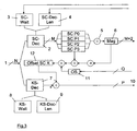
- Fig. 1 shows an example of an evaluation of a magnetic field measurement with a Hall sensor, which is operated in a known manner in Spinning-Current-Technik with four phases.
- the connection of the Hall sensor for switching the individual phases as well Any other analog components such as a commonly used preamplifier for amplifying the output signals of the Hall sensor and the required analog-to-digital converter, in this example a ⁇ modulator are not shown in this and the following figures.
- these components are well known in the art of current or magnetic field measurement with Hall sensors, for example, from the publication by A. Kerlain et al. Mentioned in the introduction.
- the output signal of the Hall element is fed with or without preamplifier to a ⁇ modulator of the first order, which digitizes the signal.
- the analog integrator of the ⁇ modulator is cleared before each new measurement of a spinning current phase.
- the digital signal sequence 1 of the ⁇ modulator is fed to a decimation filter 2 (simple digital accumulator).
- the decimation filter 2 (SC-Dec) is cleared in the prior art method at the beginning of each spinning current (SC) cycle after the previous measurement result has been taken over by the system.
- SC wait number of clocks that will not be summed up.
- SC-Dec-Len decimation length, also referred to as Tap
- the fast measured values are obtained from the digital signal sequence 1 of the ⁇ modulator, the a second decimator 7 (KS-Dec) are supplied.
- the calculation of the second sampled values takes place in the same way as the calculation of the first sampled values in the first decimator 2.
- the waiting time 8 (KS wait: number of clocks which is not summed up) after switching the SC phase in this case preferably shorter than the first waiting time 3 (SC wait) for the formation of the first samples.
- the second time period 9 (KS-Dec-Len: decimation length) over which the digital signals of the ⁇ -modulator are then summed up to form the second samples is chosen to be shorter than the first time period 4 (SC-Dec-Len) for the Formation of the first samples.
- the second sampled values are corrected in accordance with the offset values calculated from the SC measured value 6, so that as a result fast measured values 10 of the current or magnetic field can be output.
- Fig. 3 shows the offset correction of the fast measured value with this scaling of the measured offset values corresponding to the ratio of the decimation lengths. This is done here by presetting the offset scaling factor 11 (OS), with which the offset values calculated from the SC measured value 6 and the single-phase measured values SCP0-SCP3 are multiplied. The correspondingly corrected offset 12 is then subtracted correspondingly from the second samples.
- OS offset scaling factor 11
- a second additional correction becomes necessary when additional magnetic fields are introduced into the system. This can e.g. be the case if the sensitivity of the measuring system is to be measured with a constant current with the help of an integrated magnetic field coil. With appropriate application, this can even be carried out simultaneously with the measurement of the magnetic fields or currents without losing measured values.
- the magnetic field stroke is known to the system by the additionally introduced magnetic fields and can be subsequently subtracted from the fast measured values.
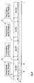
- both measuring cycles should run synchronously so that the waiting time of the fast measurement (second waiting time) starts simultaneously with a waiting time of the slow measuring (first waiting time), since then switching between the spinning current phases.
- the Umschaltevor réelle 13 the first and second waiting time 3, 8 and the first and second period 4, 9 for the fast and accurate measurement are indicated.
- the waiting times of the fast measurement are significantly shorter than those of the exact measurement. However, this is permissible since only a lower accuracy is expected from the fast measured values.
Landscapes
- Physics & Mathematics (AREA)
- General Physics & Mathematics (AREA)
- Condensed Matter Physics & Semiconductors (AREA)
- Measuring Magnetic Variables (AREA)
- Measurement Of Current Or Voltage (AREA)
- Measuring Instrument Details And Bridges, And Automatic Balancing Devices (AREA)
Claims (9)
- Procédé de mesure de courants ou de champs magnétiques avec au moins un capteur à effet Hall, qui fonctionne selon la technique de courant tournant (spinning current), dans lequel- des signaux de capteur du capteur à effet Hall sont convertis avec un convertisseur analogique à numérique en signaux numériques (1),- les signaux numériques (1) du convertisseur analogique à numérique sont lus et pour chaque phase de courant tournant sont combinés sur une première période (4) pour obtenir un premier échantillon et- les premiers échantillons des phases de courant tournant d'un cycle de courant tournant (6) sont additionnés pour former une valeur de mesure de courant tournant du courant ou du champ magnétique,caractérisé en ce que- les signaux numériques (1) du convertisseur analogique à numérique pour chaque phase de courant tournant sont combinés plusieurs fois sur respectivement une deuxième période (9), qui est plus petite que la première période (4), pour obtenir plusieurs deuxièmes échantillons en séquence temporelle,- d'après la valeur de mesure de courant tournant (6) pour chaque phase de courant tournant, un décalage (10) des premiers échantillons est calculé et les deuxièmes d'échantillons sont corrigés sur la base de ce décalage pour obtenir une valeur de mesure rapide corrigée par décalage du courant ou du champ magnétique.
- Procédé selon la revendication 1,
caractérisé en ce que
après chaque commutation (13) de la phase de courant tournant un premier temps d'attente (3) entre la commutation (13) de la phase de courant tournant et le début de la première période (4) est appliquée pour la formation des premiers échantillons. - Procédé selon la revendication 2,
caractérisé en ce que
après chaque commutation (13) de la phase de courant tournant un deuxième temps d'attente (8) entre la commutation (13) de la phase de courant tournant et le début de la deuxième période (9) est appliquée pour la formation des deuxièmes échantillons, qui est égal au premier temps d'attente (3) ou inférieur au premier temps d'attente (3). - Procédé selon une des revendications 1 à 3,
caractérisé en ce que
les signaux de capteur du capteur à effet Hall sont convertis avec un convertisseur delta-sigma du premier ordre en signaux numériques (1). - Procédé selon une des revendications 1 à 4
caractérisé en ce que
les signaux de capteur du capteur à effet Hall sont amplifiés avant la conversion analogique à numérique. - Procédé selon une des revendications 1 à 5,
caractérisé en ce que
la combinaison des signaux numériques (1) sur la première période (4) est effectuée par un premier décimateur (2) et la combinaison des signaux numériques (1) sur la deuxième période (9) est effectué par un deuxième décimateur (7). - Dispositif de mesure de courants ou de champs magnétiques comportant au moins un capteur à effet Hall, qui fonctionne selon la technique de courant tournant (spinning current), dans lequel le dispositif comprend au moins :- un convertisseur analogique à numérique, avec lequel des signaux de capteur du capteur à effet Hall sont convertis en signaux numériques (1),- un premier combinateur (2), qui lit les signaux numériques (1) du convertisseur analogique à numérique et combine pour chaque phase de courant tournant sur une première période (4), afin d'obtenir un premier échantillon et- un sommateur (5), qui additionne les premiers échantillons des phases de courant tournant d'un cycle de courant tournant pour former une valeur de mesure de courant tournant (6) du courant ou du champ magnétique,caractérisé en ce que- un deuxième combinateur (7), qui combine les signaux numériques (1) du convertisseur analogique à numérique pour chaque phase de courant tournant plusieurs fois sur respectivement une deuxième période (9), qui est plus petite que la première période (4), afin d'obtenir plusieurs deuxièmes échantillons en séquence temporelle et- une unité de correction, qui d'après la valeur de mesure de courant tournant (6) pour chaque phase de courant tournant calcule un décalage des premiers échantillons et corrige les deuxièmes échantillons sur la base de ce décalage, afin d'obtenir des valeurs de mesure (9) rapides corrigées par décalage du courant ou du champ magnétique.
- Dispositif selon la revendication 7,
caractérisé en ce que
le convertisseur analogique à numérique est un convertisseur delta sigma du premier ordre. - Dispositif selon la revendication 7 ou 8,
caractérisé en ce que
le premier combinateur (2) et le deuxième combinateur (7) est respectivement un décimateur.
Applications Claiming Priority (2)
| Application Number | Priority Date | Filing Date | Title |
|---|---|---|---|
| DE102012003978A DE102012003978A1 (de) | 2012-02-28 | 2012-02-28 | Verfahren und Vorrichtung zur Messung von Strömen oder Magnetfeldern mit Hall-Sensoren |
| PCT/EP2013/000564 WO2013127522A1 (fr) | 2012-02-28 | 2013-02-26 | Procédé et dispositif de mesure de courants ou de champs magnétiques au moyen de capteurs à effet hall |
Publications (2)
| Publication Number | Publication Date |
|---|---|
| EP2820438A1 EP2820438A1 (fr) | 2015-01-07 |
| EP2820438B1 true EP2820438B1 (fr) | 2016-05-25 |
Family
ID=47790134
Family Applications (1)
| Application Number | Title | Priority Date | Filing Date |
|---|---|---|---|
| EP13707276.5A Active EP2820438B1 (fr) | 2012-02-28 | 2013-02-26 | Procédé et dispositif de mesure de courants ou de champs magnétiques au moyen de capteurs à effet hall |
Country Status (7)
| Country | Link |
|---|---|
| US (1) | US9983235B2 (fr) |
| EP (1) | EP2820438B1 (fr) |
| JP (1) | JP2015508168A (fr) |
| CN (1) | CN104220888B (fr) |
| CA (1) | CA2863916A1 (fr) |
| DE (1) | DE102012003978A1 (fr) |
| WO (1) | WO2013127522A1 (fr) |
Families Citing this family (3)
| Publication number | Priority date | Publication date | Assignee | Title |
|---|---|---|---|---|
| DE102013221557A1 (de) * | 2013-10-23 | 2015-04-23 | Siemens Aktiengesellschaft | Messen eines Stromes |
| DE102013223394B4 (de) * | 2013-11-15 | 2015-07-16 | Fraunhofer-Gesellschaft zur Förderung der angewandten Forschung e.V. | Elektrische Schaltung |
| EP4683151A3 (fr) * | 2021-12-29 | 2026-04-15 | Melexis Technologies SA | Dispositif de capteur de courant |
Family Cites Families (10)
| Publication number | Priority date | Publication date | Assignee | Title |
|---|---|---|---|---|
| DE102004010362B4 (de) * | 2004-03-03 | 2010-11-25 | Austriamicrosystems Ag | Sensor, insbesondere Magnetfeldsensor, mit Störsignal-Kompensation und Verfahren zur Störsignal-Kompensation eines Sensors |
| DE102006059421B4 (de) * | 2006-07-14 | 2011-06-01 | Fraunhofer-Gesellschaft zur Förderung der angewandten Forschung e.V. | Verfahren zur Verarbeitung von Offset-behafteten Sensorsignalen sowie für die Durchführung des Verfahrens ausgebildete Sensoranordnung |
| US7358880B1 (en) * | 2007-02-07 | 2008-04-15 | Cirrus Logic, Inc. | Magnetic field feedback delta-sigma modulator sensor circuit |
| JP2008309626A (ja) | 2007-06-14 | 2008-12-25 | Oki Electric Ind Co Ltd | 感磁出力ic |
| US8154281B2 (en) | 2008-04-17 | 2012-04-10 | Infineon Technologies Ag | Sensor system wherein spinning phases of the spinning current hall sensor are lengthened in residual offset adjustment |
| EP2149797B1 (fr) * | 2008-08-01 | 2012-05-02 | Micronas GmbH | Procédé et dispositif de mesure d'un angle selon lequel un champ magnétique est agencé dans un plan par rapport à un axe de référence |
| DE102009006546B4 (de) * | 2009-01-29 | 2017-03-23 | Austriamicrosystems Ag | Schaltungsanordnung und Verfahren zum Bereitstellen eines aufbereiteten Messsignals |
| JP5350834B2 (ja) * | 2009-02-23 | 2013-11-27 | セイコーインスツル株式会社 | 磁気検出回路 |
| US20110006763A1 (en) * | 2009-07-07 | 2011-01-13 | Anthonius Bakker | Hall effect current sensor system and associated flip-chip packaging |
| US9094015B2 (en) * | 2011-01-14 | 2015-07-28 | Infineon Technologies Ag | Low-power activation circuit with magnetic motion sensor |
-
2012
- 2012-02-28 DE DE102012003978A patent/DE102012003978A1/de not_active Withdrawn
-
2013
- 2013-02-26 CA CA2863916A patent/CA2863916A1/fr not_active Abandoned
- 2013-02-26 CN CN201380011391.0A patent/CN104220888B/zh not_active Expired - Fee Related
- 2013-02-26 US US14/380,388 patent/US9983235B2/en active Active
- 2013-02-26 EP EP13707276.5A patent/EP2820438B1/fr active Active
- 2013-02-26 JP JP2014558038A patent/JP2015508168A/ja active Pending
- 2013-02-26 WO PCT/EP2013/000564 patent/WO2013127522A1/fr not_active Ceased
Also Published As
| Publication number | Publication date |
|---|---|
| WO2013127522A1 (fr) | 2013-09-06 |
| EP2820438A1 (fr) | 2015-01-07 |
| CA2863916A1 (fr) | 2013-09-06 |
| US20150042326A1 (en) | 2015-02-12 |
| JP2015508168A (ja) | 2015-03-16 |
| DE102012003978A1 (de) | 2013-08-29 |
| CN104220888B (zh) | 2016-10-26 |
| US9983235B2 (en) | 2018-05-29 |
| CN104220888A (zh) | 2014-12-17 |
Similar Documents
| Publication | Publication Date | Title |
|---|---|---|
| DE102013105231B4 (de) | Systeme und verfahren zur offsetfehlerkompensation in sensoren | |
| EP2041874B1 (fr) | Procédé de traitement de signaux de capteur présentant un décalage et dispositif capteur conçu pour la réalisation du procédé | |
| DE102004010707B4 (de) | Energiezähleranordnung und Verfahren zum Kalibrieren | |
| EP2443419B1 (fr) | Procédé et dispositif pour déterminer la valeur de position fine d'un corps mobile | |
| WO2000060366A1 (fr) | Mesureur de courant | |
| DE102009039672A1 (de) | Verfahren zur Bestimmung der Rotorlage einer feldorientiert betriebenen Synchronmaschine | |
| EP2666023A1 (fr) | Dispositif de mesure de courant | |
| DE102013213508A1 (de) | Verfahren und Vorrichtung zur Strommessung an einem Umrichter | |
| DE102018201310B4 (de) | Stromsensor und Schutzschalter | |
| EP2820438B1 (fr) | Procédé et dispositif de mesure de courants ou de champs magnétiques au moyen de capteurs à effet hall | |
| DE10062292A1 (de) | Meßanordnung, insbesondere zur Erfassung von Magnetfeldern | |
| DE10045670B4 (de) | Stromerfassungsvorrichtung und Stromerfassungsverfahren | |
| EP2959306B1 (fr) | Appareil de mesure de puissance à étalonnage interne de détecteurs à diodes | |
| EP2021812B1 (fr) | Dispositif de mesure comprenant un amplificateur de tension continue à contre-réaction | |
| DE10311028A1 (de) | Verfahren zur Bestimmung einer Startrotorlage und Drehzahl bei Impulsfreigabe einer stromrichtergespeisten, permanenterregten Synchronmaschine ohne Lage-und Drehzahlgeber | |
| DE19955342A1 (de) | Anordnung zum Messen des Effektivwertes einer Wechselspannung über einen großen Dynamikbereich, insbesondere zum Messen der elektrischen Leitung | |
| DE102010019484B9 (de) | Sensoranordnung und Verfahren zum Betreiben einer Sensoranordnung | |
| WO2015078448A1 (fr) | Palpeur de mesure inductif et procédé permettant de faire fonctionner un palpeur de mesure inductif | |
| EP0165512B1 (fr) | Procédé d'évaluation de la différence entre une tension alternative et une deuxième tension et dispositif de mesure pour son application | |
| EP0686850A1 (fr) | Circuit de mesure de courants continus avec isolation de tension entre le circuit de courant et le circuit de mesure | |
| EP2169797B1 (fr) | Méthode et dispositif de mesure du courant de sortie d'un circuit en pont contrôlé | |
| DE102010019485B4 (de) | Sensoranordnung und Verfahren zum Betreiben einer Sensoranordnung | |
| DE102019134077B4 (de) | Signalverarbeitungsschaltung für einen Hall-Sensor und Signalverarbeitungsverfahren | |
| DE102005025588B4 (de) | Anordnung zur Positionsmessung bei einer magnetisch gelagerten Welle | |
| WO2016112903A1 (fr) | Procédé et unité de traitement de signaux de mesure pour la génération d'un signal de mesure multicanal pour une mesure de vitesse de rotation, ainsi qu'unité capteur |
Legal Events
| Date | Code | Title | Description |
|---|---|---|---|
| PUAI | Public reference made under article 153(3) epc to a published international application that has entered the european phase |
Free format text: ORIGINAL CODE: 0009012 |
|
| 17P | Request for examination filed |
Effective date: 20140813 |
|
| AK | Designated contracting states |
Kind code of ref document: A1 Designated state(s): AL AT BE BG CH CY CZ DE DK EE ES FI FR GB GR HR HU IE IS IT LI LT LU LV MC MK MT NL NO PL PT RO RS SE SI SK SM TR |
|
| AX | Request for extension of the european patent |
Extension state: BA ME |
|
| DAX | Request for extension of the european patent (deleted) | ||
| GRAP | Despatch of communication of intention to grant a patent |
Free format text: ORIGINAL CODE: EPIDOSNIGR1 |
|
| INTG | Intention to grant announced |
Effective date: 20151207 |
|
| GRAS | Grant fee paid |
Free format text: ORIGINAL CODE: EPIDOSNIGR3 |
|
| GRAA | (expected) grant |
Free format text: ORIGINAL CODE: 0009210 |
|
| AK | Designated contracting states |
Kind code of ref document: B1 Designated state(s): AL AT BE BG CH CY CZ DE DK EE ES FI FR GB GR HR HU IE IS IT LI LT LU LV MC MK MT NL NO PL PT RO RS SE SI SK SM TR |
|
| REG | Reference to a national code |
Ref country code: GB Ref legal event code: FG4D Free format text: NOT ENGLISH |
|
| REG | Reference to a national code |
Ref country code: CH Ref legal event code: EP |
|
| REG | Reference to a national code |
Ref country code: IE Ref legal event code: FG4D Free format text: LANGUAGE OF EP DOCUMENT: GERMAN Ref country code: AT Ref legal event code: REF Ref document number: 802734 Country of ref document: AT Kind code of ref document: T Effective date: 20160615 |
|
| REG | Reference to a national code |
Ref country code: DE Ref legal event code: R096 Ref document number: 502013003144 Country of ref document: DE |
|
| REG | Reference to a national code |
Ref country code: LT Ref legal event code: MG4D |
|
| REG | Reference to a national code |
Ref country code: NL Ref legal event code: MP Effective date: 20160525 |
|
| PG25 | Lapsed in a contracting state [announced via postgrant information from national office to epo] |
Ref country code: LT Free format text: LAPSE BECAUSE OF FAILURE TO SUBMIT A TRANSLATION OF THE DESCRIPTION OR TO PAY THE FEE WITHIN THE PRESCRIBED TIME-LIMIT Effective date: 20160525 Ref country code: NL Free format text: LAPSE BECAUSE OF FAILURE TO SUBMIT A TRANSLATION OF THE DESCRIPTION OR TO PAY THE FEE WITHIN THE PRESCRIBED TIME-LIMIT Effective date: 20160525 Ref country code: NO Free format text: LAPSE BECAUSE OF FAILURE TO SUBMIT A TRANSLATION OF THE DESCRIPTION OR TO PAY THE FEE WITHIN THE PRESCRIBED TIME-LIMIT Effective date: 20160825 Ref country code: FI Free format text: LAPSE BECAUSE OF FAILURE TO SUBMIT A TRANSLATION OF THE DESCRIPTION OR TO PAY THE FEE WITHIN THE PRESCRIBED TIME-LIMIT Effective date: 20160525 |
|
| PG25 | Lapsed in a contracting state [announced via postgrant information from national office to epo] |
Ref country code: SE Free format text: LAPSE BECAUSE OF FAILURE TO SUBMIT A TRANSLATION OF THE DESCRIPTION OR TO PAY THE FEE WITHIN THE PRESCRIBED TIME-LIMIT Effective date: 20160525 Ref country code: GR Free format text: LAPSE BECAUSE OF FAILURE TO SUBMIT A TRANSLATION OF THE DESCRIPTION OR TO PAY THE FEE WITHIN THE PRESCRIBED TIME-LIMIT Effective date: 20160826 Ref country code: PT Free format text: LAPSE BECAUSE OF FAILURE TO SUBMIT A TRANSLATION OF THE DESCRIPTION OR TO PAY THE FEE WITHIN THE PRESCRIBED TIME-LIMIT Effective date: 20160926 Ref country code: RS Free format text: LAPSE BECAUSE OF FAILURE TO SUBMIT A TRANSLATION OF THE DESCRIPTION OR TO PAY THE FEE WITHIN THE PRESCRIBED TIME-LIMIT Effective date: 20160525 Ref country code: LV Free format text: LAPSE BECAUSE OF FAILURE TO SUBMIT A TRANSLATION OF THE DESCRIPTION OR TO PAY THE FEE WITHIN THE PRESCRIBED TIME-LIMIT Effective date: 20160525 Ref country code: ES Free format text: LAPSE BECAUSE OF FAILURE TO SUBMIT A TRANSLATION OF THE DESCRIPTION OR TO PAY THE FEE WITHIN THE PRESCRIBED TIME-LIMIT Effective date: 20160525 |
|
| PG25 | Lapsed in a contracting state [announced via postgrant information from national office to epo] |
Ref country code: IT Free format text: LAPSE BECAUSE OF FAILURE TO SUBMIT A TRANSLATION OF THE DESCRIPTION OR TO PAY THE FEE WITHIN THE PRESCRIBED TIME-LIMIT Effective date: 20160525 |
|
| PG25 | Lapsed in a contracting state [announced via postgrant information from national office to epo] |
Ref country code: DK Free format text: LAPSE BECAUSE OF FAILURE TO SUBMIT A TRANSLATION OF THE DESCRIPTION OR TO PAY THE FEE WITHIN THE PRESCRIBED TIME-LIMIT Effective date: 20160525 Ref country code: CZ Free format text: LAPSE BECAUSE OF FAILURE TO SUBMIT A TRANSLATION OF THE DESCRIPTION OR TO PAY THE FEE WITHIN THE PRESCRIBED TIME-LIMIT Effective date: 20160525 Ref country code: SK Free format text: LAPSE BECAUSE OF FAILURE TO SUBMIT A TRANSLATION OF THE DESCRIPTION OR TO PAY THE FEE WITHIN THE PRESCRIBED TIME-LIMIT Effective date: 20160525 Ref country code: EE Free format text: LAPSE BECAUSE OF FAILURE TO SUBMIT A TRANSLATION OF THE DESCRIPTION OR TO PAY THE FEE WITHIN THE PRESCRIBED TIME-LIMIT Effective date: 20160525 Ref country code: RO Free format text: LAPSE BECAUSE OF FAILURE TO SUBMIT A TRANSLATION OF THE DESCRIPTION OR TO PAY THE FEE WITHIN THE PRESCRIBED TIME-LIMIT Effective date: 20160525 |
|
| PG25 | Lapsed in a contracting state [announced via postgrant information from national office to epo] |
Ref country code: SM Free format text: LAPSE BECAUSE OF FAILURE TO SUBMIT A TRANSLATION OF THE DESCRIPTION OR TO PAY THE FEE WITHIN THE PRESCRIBED TIME-LIMIT Effective date: 20160525 Ref country code: PL Free format text: LAPSE BECAUSE OF FAILURE TO SUBMIT A TRANSLATION OF THE DESCRIPTION OR TO PAY THE FEE WITHIN THE PRESCRIBED TIME-LIMIT Effective date: 20160525 |
|
| REG | Reference to a national code |
Ref country code: DE Ref legal event code: R097 Ref document number: 502013003144 Country of ref document: DE Ref country code: FR Ref legal event code: PLFP Year of fee payment: 5 |
|
| PLBE | No opposition filed within time limit |
Free format text: ORIGINAL CODE: 0009261 |
|
| STAA | Information on the status of an ep patent application or granted ep patent |
Free format text: STATUS: NO OPPOSITION FILED WITHIN TIME LIMIT |
|
| 26N | No opposition filed |
Effective date: 20170228 |
|
| PG25 | Lapsed in a contracting state [announced via postgrant information from national office to epo] |
Ref country code: BE Free format text: LAPSE BECAUSE OF NON-PAYMENT OF DUE FEES Effective date: 20170228 Ref country code: SI Free format text: LAPSE BECAUSE OF FAILURE TO SUBMIT A TRANSLATION OF THE DESCRIPTION OR TO PAY THE FEE WITHIN THE PRESCRIBED TIME-LIMIT Effective date: 20160525 |
|
| PG25 | Lapsed in a contracting state [announced via postgrant information from national office to epo] |
Ref country code: MC Free format text: LAPSE BECAUSE OF FAILURE TO SUBMIT A TRANSLATION OF THE DESCRIPTION OR TO PAY THE FEE WITHIN THE PRESCRIBED TIME-LIMIT Effective date: 20160525 |
|
| REG | Reference to a national code |
Ref country code: CH Ref legal event code: PL |
|
| PG25 | Lapsed in a contracting state [announced via postgrant information from national office to epo] |
Ref country code: LI Free format text: LAPSE BECAUSE OF NON-PAYMENT OF DUE FEES Effective date: 20170228 Ref country code: CH Free format text: LAPSE BECAUSE OF NON-PAYMENT OF DUE FEES Effective date: 20170228 |
|
| REG | Reference to a national code |
Ref country code: IE Ref legal event code: MM4A |
|
| PG25 | Lapsed in a contracting state [announced via postgrant information from national office to epo] |
Ref country code: LU Free format text: LAPSE BECAUSE OF NON-PAYMENT OF DUE FEES Effective date: 20170226 |
|
| REG | Reference to a national code |
Ref country code: BE Ref legal event code: MM Effective date: 20170228 |
|
| REG | Reference to a national code |
Ref country code: FR Ref legal event code: PLFP Year of fee payment: 6 |
|
| PG25 | Lapsed in a contracting state [announced via postgrant information from national office to epo] |
Ref country code: IE Free format text: LAPSE BECAUSE OF NON-PAYMENT OF DUE FEES Effective date: 20170226 |
|
| PG25 | Lapsed in a contracting state [announced via postgrant information from national office to epo] |
Ref country code: MT Free format text: LAPSE BECAUSE OF FAILURE TO SUBMIT A TRANSLATION OF THE DESCRIPTION OR TO PAY THE FEE WITHIN THE PRESCRIBED TIME-LIMIT Effective date: 20160525 |
|
| PG25 | Lapsed in a contracting state [announced via postgrant information from national office to epo] |
Ref country code: AL Free format text: LAPSE BECAUSE OF FAILURE TO SUBMIT A TRANSLATION OF THE DESCRIPTION OR TO PAY THE FEE WITHIN THE PRESCRIBED TIME-LIMIT Effective date: 20160525 |
|
| REG | Reference to a national code |
Ref country code: AT Ref legal event code: MM01 Ref document number: 802734 Country of ref document: AT Kind code of ref document: T Effective date: 20180226 |
|
| PG25 | Lapsed in a contracting state [announced via postgrant information from national office to epo] |
Ref country code: AT Free format text: LAPSE BECAUSE OF NON-PAYMENT OF DUE FEES Effective date: 20180226 |
|
| PG25 | Lapsed in a contracting state [announced via postgrant information from national office to epo] |
Ref country code: HU Free format text: LAPSE BECAUSE OF FAILURE TO SUBMIT A TRANSLATION OF THE DESCRIPTION OR TO PAY THE FEE WITHIN THE PRESCRIBED TIME-LIMIT; INVALID AB INITIO Effective date: 20130226 |
|
| PG25 | Lapsed in a contracting state [announced via postgrant information from national office to epo] |
Ref country code: BG Free format text: LAPSE BECAUSE OF FAILURE TO SUBMIT A TRANSLATION OF THE DESCRIPTION OR TO PAY THE FEE WITHIN THE PRESCRIBED TIME-LIMIT Effective date: 20160525 |
|
| PG25 | Lapsed in a contracting state [announced via postgrant information from national office to epo] |
Ref country code: CY Free format text: LAPSE BECAUSE OF FAILURE TO SUBMIT A TRANSLATION OF THE DESCRIPTION OR TO PAY THE FEE WITHIN THE PRESCRIBED TIME-LIMIT Effective date: 20160525 |
|
| PG25 | Lapsed in a contracting state [announced via postgrant information from national office to epo] |
Ref country code: MK Free format text: LAPSE BECAUSE OF FAILURE TO SUBMIT A TRANSLATION OF THE DESCRIPTION OR TO PAY THE FEE WITHIN THE PRESCRIBED TIME-LIMIT Effective date: 20160525 |
|
| PG25 | Lapsed in a contracting state [announced via postgrant information from national office to epo] |
Ref country code: TR Free format text: LAPSE BECAUSE OF FAILURE TO SUBMIT A TRANSLATION OF THE DESCRIPTION OR TO PAY THE FEE WITHIN THE PRESCRIBED TIME-LIMIT Effective date: 20160525 |
|
| PGFP | Annual fee paid to national office [announced via postgrant information from national office to epo] |
Ref country code: GB Payment date: 20200225 Year of fee payment: 8 |
|
| PG25 | Lapsed in a contracting state [announced via postgrant information from national office to epo] |
Ref country code: HR Free format text: LAPSE BECAUSE OF FAILURE TO SUBMIT A TRANSLATION OF THE DESCRIPTION OR TO PAY THE FEE WITHIN THE PRESCRIBED TIME-LIMIT Effective date: 20160525 |
|
| PGFP | Annual fee paid to national office [announced via postgrant information from national office to epo] |
Ref country code: FR Payment date: 20200219 Year of fee payment: 8 |
|
| PG25 | Lapsed in a contracting state [announced via postgrant information from national office to epo] |
Ref country code: IS Free format text: LAPSE BECAUSE OF FAILURE TO SUBMIT A TRANSLATION OF THE DESCRIPTION OR TO PAY THE FEE WITHIN THE PRESCRIBED TIME-LIMIT Effective date: 20160925 |
|
| GBPC | Gb: european patent ceased through non-payment of renewal fee |
Effective date: 20210226 |
|
| PG25 | Lapsed in a contracting state [announced via postgrant information from national office to epo] |
Ref country code: GB Free format text: LAPSE BECAUSE OF NON-PAYMENT OF DUE FEES Effective date: 20210226 Ref country code: FR Free format text: LAPSE BECAUSE OF NON-PAYMENT OF DUE FEES Effective date: 20210228 |
|
| P01 | Opt-out of the competence of the unified patent court (upc) registered |
Effective date: 20230524 |
|
| PGFP | Annual fee paid to national office [announced via postgrant information from national office to epo] |
Ref country code: DE Payment date: 20260217 Year of fee payment: 14 |