EP2821269A2 - Appareil d'alimentation électrique de véhicule, pour un démarreur/générateur combiné - Google Patents
Appareil d'alimentation électrique de véhicule, pour un démarreur/générateur combiné Download PDFInfo
- Publication number
- EP2821269A2 EP2821269A2 EP14174306.2A EP14174306A EP2821269A2 EP 2821269 A2 EP2821269 A2 EP 2821269A2 EP 14174306 A EP14174306 A EP 14174306A EP 2821269 A2 EP2821269 A2 EP 2821269A2
- Authority
- EP
- European Patent Office
- Prior art keywords
- power source
- vehicle
- internal combustion
- combustion engine
- electric power
- Prior art date
- Legal status (The legal status is an assumption and is not a legal conclusion. Google has not performed a legal analysis and makes no representation as to the accuracy of the status listed.)
- Ceased
Links
Images






Classifications
-
- F—MECHANICAL ENGINEERING; LIGHTING; HEATING; WEAPONS; BLASTING
- F02—COMBUSTION ENGINES; HOT-GAS OR COMBUSTION-PRODUCT ENGINE PLANTS
- F02N—STARTING OF COMBUSTION ENGINES; STARTING AIDS FOR SUCH ENGINES, NOT OTHERWISE PROVIDED FOR
- F02N11/00—Starting of engines by means of electric motors
- F02N11/08—Circuits specially adapted for starting of engines
- F02N11/0862—Circuits specially adapted for starting of engines characterised by the electrical power supply means, e.g. battery
- F02N11/0866—Circuits specially adapted for starting of engines characterised by the electrical power supply means, e.g. battery comprising several power sources, e.g. battery and capacitor or two batteries
-
- B—PERFORMING OPERATIONS; TRANSPORTING
- B60—VEHICLES IN GENERAL
- B60L—PROPULSION OF ELECTRICALLY-PROPELLED VEHICLES; SUPPLYING ELECTRIC POWER FOR AUXILIARY EQUIPMENT OF ELECTRICALLY-PROPELLED VEHICLES; ELECTRODYNAMIC BRAKE SYSTEMS FOR VEHICLES IN GENERAL; MAGNETIC SUSPENSION OR LEVITATION FOR VEHICLES; MONITORING OPERATING VARIABLES OF ELECTRICALLY-PROPELLED VEHICLES; ELECTRIC SAFETY DEVICES FOR ELECTRICALLY-PROPELLED VEHICLES
- B60L58/00—Methods or circuit arrangements for monitoring or controlling batteries or fuel cells, specially adapted for electric vehicles
- B60L58/10—Methods or circuit arrangements for monitoring or controlling batteries or fuel cells, specially adapted for electric vehicles for monitoring or controlling batteries
- B60L58/18—Methods or circuit arrangements for monitoring or controlling batteries or fuel cells, specially adapted for electric vehicles for monitoring or controlling batteries of two or more battery modules
- B60L58/20—Methods or circuit arrangements for monitoring or controlling batteries or fuel cells, specially adapted for electric vehicles for monitoring or controlling batteries of two or more battery modules having different nominal voltages
-
- B—PERFORMING OPERATIONS; TRANSPORTING
- B60—VEHICLES IN GENERAL
- B60L—PROPULSION OF ELECTRICALLY-PROPELLED VEHICLES; SUPPLYING ELECTRIC POWER FOR AUXILIARY EQUIPMENT OF ELECTRICALLY-PROPELLED VEHICLES; ELECTRODYNAMIC BRAKE SYSTEMS FOR VEHICLES IN GENERAL; MAGNETIC SUSPENSION OR LEVITATION FOR VEHICLES; MONITORING OPERATING VARIABLES OF ELECTRICALLY-PROPELLED VEHICLES; ELECTRIC SAFETY DEVICES FOR ELECTRICALLY-PROPELLED VEHICLES
- B60L7/00—Electrodynamic brake systems for vehicles in general
- B60L7/10—Dynamic electric regenerative braking
-
- B—PERFORMING OPERATIONS; TRANSPORTING
- B60—VEHICLES IN GENERAL
- B60R—VEHICLES, VEHICLE FITTINGS, OR VEHICLE PARTS, NOT OTHERWISE PROVIDED FOR
- B60R16/00—Electric or fluid circuits specially adapted for vehicles and not otherwise provided for; Arrangement of elements of electric or fluid circuits specially adapted for vehicles and not otherwise provided for
- B60R16/02—Electric or fluid circuits specially adapted for vehicles and not otherwise provided for; Arrangement of elements of electric or fluid circuits specially adapted for vehicles and not otherwise provided for electric constitutive elements
- B60R16/03—Electric or fluid circuits specially adapted for vehicles and not otherwise provided for; Arrangement of elements of electric or fluid circuits specially adapted for vehicles and not otherwise provided for electric constitutive elements for supply of electrical power to vehicle subsystems or for
-
- F—MECHANICAL ENGINEERING; LIGHTING; HEATING; WEAPONS; BLASTING
- F02—COMBUSTION ENGINES; HOT-GAS OR COMBUSTION-PRODUCT ENGINE PLANTS
- F02N—STARTING OF COMBUSTION ENGINES; STARTING AIDS FOR SUCH ENGINES, NOT OTHERWISE PROVIDED FOR
- F02N11/00—Starting of engines by means of electric motors
- F02N11/08—Circuits specially adapted for starting of engines
- F02N11/0814—Circuits specially adapted for starting of engines comprising means for controlling automatic idle-start-stop
- F02N11/0844—Circuits specially adapted for starting of engines comprising means for controlling automatic idle-start-stop with means for restarting the engine directly after an engine stop request, e.g. caused by change of driver mind
-
- F—MECHANICAL ENGINEERING; LIGHTING; HEATING; WEAPONS; BLASTING
- F02—COMBUSTION ENGINES; HOT-GAS OR COMBUSTION-PRODUCT ENGINE PLANTS
- F02N—STARTING OF COMBUSTION ENGINES; STARTING AIDS FOR SUCH ENGINES, NOT OTHERWISE PROVIDED FOR
- F02N11/00—Starting of engines by means of electric motors
- F02N11/08—Circuits specially adapted for starting of engines
- F02N11/0848—Circuits specially adapted for starting of engines with means for detecting successful engine start, e.g. to stop starter actuation
-
- F—MECHANICAL ENGINEERING; LIGHTING; HEATING; WEAPONS; BLASTING
- F02—COMBUSTION ENGINES; HOT-GAS OR COMBUSTION-PRODUCT ENGINE PLANTS
- F02N—STARTING OF COMBUSTION ENGINES; STARTING AIDS FOR SUCH ENGINES, NOT OTHERWISE PROVIDED FOR
- F02N11/00—Starting of engines by means of electric motors
- F02N11/08—Circuits specially adapted for starting of engines
- F02N11/087—Details of the switching means in starting circuits, e.g. relays or electronic switches
-
- F—MECHANICAL ENGINEERING; LIGHTING; HEATING; WEAPONS; BLASTING
- F02—COMBUSTION ENGINES; HOT-GAS OR COMBUSTION-PRODUCT ENGINE PLANTS
- F02N—STARTING OF COMBUSTION ENGINES; STARTING AIDS FOR SUCH ENGINES, NOT OTHERWISE PROVIDED FOR
- F02N11/00—Starting of engines by means of electric motors
- F02N11/10—Safety devices
- F02N11/108—Safety devices for diagnosis of the starter or its components
-
- F—MECHANICAL ENGINEERING; LIGHTING; HEATING; WEAPONS; BLASTING
- F02—COMBUSTION ENGINES; HOT-GAS OR COMBUSTION-PRODUCT ENGINE PLANTS
- F02N—STARTING OF COMBUSTION ENGINES; STARTING AIDS FOR SUCH ENGINES, NOT OTHERWISE PROVIDED FOR
- F02N11/00—Starting of engines by means of electric motors
- F02N11/04—Starting of engines by means of electric motors the motors being associated with current generators
-
- F—MECHANICAL ENGINEERING; LIGHTING; HEATING; WEAPONS; BLASTING
- F02—COMBUSTION ENGINES; HOT-GAS OR COMBUSTION-PRODUCT ENGINE PLANTS
- F02N—STARTING OF COMBUSTION ENGINES; STARTING AIDS FOR SUCH ENGINES, NOT OTHERWISE PROVIDED FOR
- F02N11/00—Starting of engines by means of electric motors
- F02N11/08—Circuits specially adapted for starting of engines
- F02N11/0814—Circuits specially adapted for starting of engines comprising means for controlling automatic idle-start-stop
-
- F—MECHANICAL ENGINEERING; LIGHTING; HEATING; WEAPONS; BLASTING
- F02—COMBUSTION ENGINES; HOT-GAS OR COMBUSTION-PRODUCT ENGINE PLANTS
- F02N—STARTING OF COMBUSTION ENGINES; STARTING AIDS FOR SUCH ENGINES, NOT OTHERWISE PROVIDED FOR
- F02N11/00—Starting of engines by means of electric motors
- F02N11/08—Circuits specially adapted for starting of engines
- F02N11/0814—Circuits specially adapted for starting of engines comprising means for controlling automatic idle-start-stop
- F02N11/0818—Conditions for starting or stopping the engine or for deactivating the idle-start-stop mode
- F02N11/0825—Conditions for starting or stopping the engine or for deactivating the idle-start-stop mode related to prevention of engine restart failure, e.g. disabling automatic stop at low battery state
-
- F—MECHANICAL ENGINEERING; LIGHTING; HEATING; WEAPONS; BLASTING
- F02—COMBUSTION ENGINES; HOT-GAS OR COMBUSTION-PRODUCT ENGINE PLANTS
- F02N—STARTING OF COMBUSTION ENGINES; STARTING AIDS FOR SUCH ENGINES, NOT OTHERWISE PROVIDED FOR
- F02N11/00—Starting of engines by means of electric motors
- F02N11/08—Circuits specially adapted for starting of engines
- F02N11/087—Details of the switching means in starting circuits, e.g. relays or electronic switches
- F02N2011/0874—Details of the switching means in starting circuits, e.g. relays or electronic switches characterised by said switch being an electronic switch
-
- F—MECHANICAL ENGINEERING; LIGHTING; HEATING; WEAPONS; BLASTING
- F02—COMBUSTION ENGINES; HOT-GAS OR COMBUSTION-PRODUCT ENGINE PLANTS
- F02N—STARTING OF COMBUSTION ENGINES; STARTING AIDS FOR SUCH ENGINES, NOT OTHERWISE PROVIDED FOR
- F02N11/00—Starting of engines by means of electric motors
- F02N11/08—Circuits specially adapted for starting of engines
- F02N2011/0881—Components of the circuit not provided for by previous groups
- F02N2011/0885—Capacitors, e.g. for additional power supply
-
- F—MECHANICAL ENGINEERING; LIGHTING; HEATING; WEAPONS; BLASTING
- F02—COMBUSTION ENGINES; HOT-GAS OR COMBUSTION-PRODUCT ENGINE PLANTS
- F02N—STARTING OF COMBUSTION ENGINES; STARTING AIDS FOR SUCH ENGINES, NOT OTHERWISE PROVIDED FOR
- F02N11/00—Starting of engines by means of electric motors
- F02N11/08—Circuits specially adapted for starting of engines
- F02N2011/0881—Components of the circuit not provided for by previous groups
- F02N2011/0888—DC/DC converters
-
- F—MECHANICAL ENGINEERING; LIGHTING; HEATING; WEAPONS; BLASTING
- F02—COMBUSTION ENGINES; HOT-GAS OR COMBUSTION-PRODUCT ENGINE PLANTS
- F02N—STARTING OF COMBUSTION ENGINES; STARTING AIDS FOR SUCH ENGINES, NOT OTHERWISE PROVIDED FOR
- F02N2200/00—Parameters used for control of starting apparatus
- F02N2200/02—Parameters used for control of starting apparatus said parameters being related to the engine
- F02N2200/022—Engine speed
-
- F—MECHANICAL ENGINEERING; LIGHTING; HEATING; WEAPONS; BLASTING
- F02—COMBUSTION ENGINES; HOT-GAS OR COMBUSTION-PRODUCT ENGINE PLANTS
- F02N—STARTING OF COMBUSTION ENGINES; STARTING AIDS FOR SUCH ENGINES, NOT OTHERWISE PROVIDED FOR
- F02N2200/00—Parameters used for control of starting apparatus
- F02N2200/06—Parameters used for control of starting apparatus said parameters being related to the power supply or driving circuits for the starter
- F02N2200/063—Battery voltage
-
- Y—GENERAL TAGGING OF NEW TECHNOLOGICAL DEVELOPMENTS; GENERAL TAGGING OF CROSS-SECTIONAL TECHNOLOGIES SPANNING OVER SEVERAL SECTIONS OF THE IPC; TECHNICAL SUBJECTS COVERED BY FORMER USPC CROSS-REFERENCE ART COLLECTIONS [XRACs] AND DIGESTS
- Y02—TECHNOLOGIES OR APPLICATIONS FOR MITIGATION OR ADAPTATION AGAINST CLIMATE CHANGE
- Y02T—CLIMATE CHANGE MITIGATION TECHNOLOGIES RELATED TO TRANSPORTATION
- Y02T10/00—Road transport of goods or passengers
- Y02T10/10—Internal combustion engine [ICE] based vehicles
- Y02T10/40—Engine management systems
-
- Y—GENERAL TAGGING OF NEW TECHNOLOGICAL DEVELOPMENTS; GENERAL TAGGING OF CROSS-SECTIONAL TECHNOLOGIES SPANNING OVER SEVERAL SECTIONS OF THE IPC; TECHNICAL SUBJECTS COVERED BY FORMER USPC CROSS-REFERENCE ART COLLECTIONS [XRACs] AND DIGESTS
- Y02—TECHNOLOGIES OR APPLICATIONS FOR MITIGATION OR ADAPTATION AGAINST CLIMATE CHANGE
- Y02T—CLIMATE CHANGE MITIGATION TECHNOLOGIES RELATED TO TRANSPORTATION
- Y02T10/00—Road transport of goods or passengers
- Y02T10/60—Other road transportation technologies with climate change mitigation effect
- Y02T10/70—Energy storage systems for electromobility, e.g. batteries
Definitions
- the present invention relates to a vehicle electric power supply apparatus.
- a vehicle electric power supply apparatus which includes a DC-DC converter connecting a main power source connected to an electric load and an auxiliary power source connected to a generator that starts an engine and includes a switch between the main power source and the auxiliary power source is known (for example, refer to Japanese Unexamined Patent Application Publication No. 2010-195336 ).
- an object of an aspect of the present invention is to provide a vehicle electric power supply apparatus capable of detecting the presence or absence of an abnormality of a switch between a first power source and a second power source and preventing unintentional charge and discharge from occurring.
- Another object is to provide a vehicle electric power supply apparatus capable of appropriately starting an internal combustion engine.
- a vehicle electric power supply apparatus adopts one of the configurations described below.
- the control unit determines that an ON failure in which the switch is fixed to an ON state (hereafter simply referred to as "ON") occurs in the case that the absolute value of the difference between the output voltage of the first power source and the output voltage of the second power source is the predetermined first threshold value or less over the predetermined length of time.
- ON an ON failure in which the switch is fixed to an ON state
- the vehicle by inhibiting execution of the idle stopping in a state where restarting of the internal combustion engine from the idle stopping is not allowed (i.e., a state having a possibility that the output voltage of the first power source decreases due to the ON failure of the switch), the vehicle can be maintained to be operable.
- the control unit determines that electric power supplied from the second power source to the electric motor is actually insufficient in the case that the rotation frequency after the predetermined length of time elapses in the starting of the internal combustion engine by the electric motor is the predetermined second threshold value or less. In this case, by setting the switch to ON, it becomes possible to supply electric power from the first power source to the electric motor, and it is possible to appropriately start the internal combustion engine.
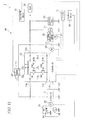
- a vehicle electric power supply apparatus 10 is, for example, as shown in FIG. 1 , mounted in a vehicle 1.
- the vehicle electric power supply apparatus 10 includes at least a capacitor 11 (second power source) as a secondary battery, a battery 12 (first power source), a DC-DC converter 13, a controller 14 (control unit, idle stopping unit), a contactor 15 (switch), and a contactor relay 16 (opening and closing unit).
- the vehicle 1 includes the vehicle electric power supply apparatus 10, an FI-ECU 17 (idle stopping unit), a starter magnet switch (STMGSW) 18, a starter relay 19, a starter motor (STM) 20 (second electric load, electric motor), a generator (ACG) 21, an internal combustion engine 22, an electric load 23 (first electric load), an ignition switch (IGSW) 24, a first voltage sensor 25 (voltage detection unit), a second voltage sensor 26 (voltage detection unit), and a rotation frequency sensor 27 (rotation frequency detection unit).
- STMGSW starter magnet switch
- STM starter motor
- ACG generator
- ACG generator
- IGSW ignition switch
- first voltage sensor 25 voltage detection unit
- second voltage sensor 26 voltage detection unit
- rotation frequency sensor 27 rotation frequency detection unit
- the capacitor 11 is, for example, an electric double layer capacitor, an electrolytic capacitor, a lithium-ion capacitor, and the like and is connected to the starter magnet switch 18.
- the capacitor 11 is connected to a first input-output terminal 13a of the DC-DC converter 13 and a first terminal 15a of the contactor 15.
- the capacitor 11 is configured to be capable of being electrically connected to the battery 12, the contactor relay 16, the FI-ECU 17, the generator 21, the electric load 23, and the ignition switch 24 via the DC-DC converter 13 or the contactor 15.
- the battery 12 is, for example, a lead battery of a predetermined voltage (12V or the like) and the like and is connected to the contactor relay 16, the FI-ECU 17, the generator 21, the electric load 23, and the ignition switch 24.
- the battery 12 is connected to a second input-output terminal 13b of the DC-DC converter 13 and a second terminal 15b of the contactor 15.
- the battery 12 is configured to be capable of being electrically connected to the capacitor 11 and the starter magnet switch 18 via the DC-DC converter 13 or the contactor 15.
- the DC-DC converter 13 is capable of increasing or decreasing voltage bi-directionally between the first input-output terminal 13a and the second input-output terminal 13b by the control of the controller 14.
- the DC-DC converter 13 charges the capacitor 11 by supplying the generated electric power that is produced by the generator 21 at the time of running of the internal combustion engine 22 or the regenerated electric power that is produced by the generator 21 at the time of braking of the vehicle 1 to the capacitor 11.
- the DC-DC converter 13 discharges the capacitor 11 by supplying the electric power stored in the capacitor 11 to at least the battery 12 or the electric load 23.
- the DC-DC converter 13 is, for example, an H-bridge step-up/step-down DC-DC converter and includes four first to fourth switching devices (for example, IGBT: Insulated Gate Bipolar mode Transistor) SW1, SW2, SW3, and SW4 that are connected in a bridge form.
- IGBT Insulated Gate Bipolar mode Transistor
- the first switching device SW1 and the second switching device SW2 are paired and are connected in series between the first input-output terminal 13a and a ground terminal 13c. That is, a collector of the first switching device SW1 is connected to the first input-output terminal 13a, an emitter of the first switching device SW1 is connected to a collector of the second switching device SW2, and an emitter of the second switching device SW2 is connected to the ground terminal 13c.
- the third switching device SW3 and the fourth switching device SW4 are paired and are connected in series between the second input-output terminal 13b and the ground terminal 13c. That is, a collector of the third switching device SW3 is connected to the second input-output terminal 13b, an emitter of the third switching device SW3 is connected to a collector of the fourth switching device SW4, and an emitter of the fourth switching device SW4 is connected to the ground terminal 13c.
- Each of first to fourth diodes D1 to D4 is connected between the emitter and the collector of each of the switching devices SW1, SW2, SW3, and SW4 such that the direction from the emitter to the collector is the forward direction.
- the DC-DC converter 13 includes a reactor L that is connected between a connecting point of the first switching device SW 1 and the second switching device SW2 and a connecting point of the third switching device SW3 and the fourth switching device SW4.
- the DC-DC converter 13 includes a first capacitor Ca that is connected between the first input-output terminal 13a and the ground terminal 13c, and a second capacitor Cb that is connected between the second input-output terminal 13b and the ground terminal 13c.
- the DC-DC converter 13 includes a resistance R and a diode D which are connected in series such that the resistance R and the diode D directly connect the first input-output terminal 13a and the second input-output terminal 13b.
- the diode D is provided such that the direction toward the first input-output terminal 13a from the second input-output terminal 13b is the forward direction of the diode.
- the DC-DC converter 13 is driven by a signal which is output from the controller 14 and is input to a gate of each of the switching devices SW1, SW2, SW3, and SW4.
- the controller 14 controls the bi-directional voltage increasing/decreasing operation of the DC-DC converter 13 and connection and disconnection operations of the contactor 15 by the contactor relay 16. Moreover, the controller 14 controls execution permission and execution inhibition of idle stopping by the FI-ECU 17 and outputs a control command that commands execution permission and execution inhibition of idle stopping to the FI-ECU 17.
- the controller 14 is capable of detecting the internal resistance and the capacitance of the capacitor 11 and determining whether or not the internal resistance is a predetermined value or more and is also capable of determining whether or not the capacitor 11 is degraded based on the internal resistance.
- the controller 14 is connected to the first voltage sensor 25 that detects the output voltage VC of the capacitor 11, a current sensor (not shown in the drawing) that detects the charge current and the discharge current of the capacitor 11, and a temperature sensor (not shown in the drawing) that detects the temperature of the capacitor 11.
- the controller 14 is capable of controlling the discharge of the battery 12 and the depth of discharge of the battery 12.
- the controller 14 is connected to the second voltage sensor 26 that detects the output voltage VB of the battery 12, a current sensor (not shown in the drawing) that detects the charge current and the discharge current of the battery 12, and a temperature sensor (not shown in the drawing) that detects the temperature of the battery 12.
- the contactor 15 switches between connection and disconnection of the first terminal 15a and the second terminal 15b of the contactor 15 corresponding to an ON state and an OFF state of the contactor relay 16.
- the controller 14 controls an ON state and an OFF state of the contactor relay 16.
- the first terminal 15a of the contactor 15 is connected to the first input-output terminal 13a of the DC-DC converter 13, a positive pole terminal of the capacitor 11, and the starter magnet switch 18.
- the second terminal 15b of the contactor 15 is connected to the second input-output terminal 13b of the DC-DC converter 13, a positive pole terminal of the battery 12, the generator 21, and the electric load 23.
- the contactor 15 connects each of the capacitor 11 and the battery 12 in parallel to the starter magnet switch 18 and the starter motor 20 that are connected in series.
- a negative pole terminal of the capacitor 11 and a negative pole terminal of the battery 12 are grounded.
- the FI-ECU 17 is, for example, an ECU (Electronic Control Unit) that is configured by an electronic circuit such as a CPU (Central Processing Unit) and performs various controls relating to operations of the internal combustion engine 22 such as fuel supply and ignition timing.
- the FI-ECU 17 controls starting and stopping of the internal combustion engine 22 by a start request signal and a stop request signal that are output from the ignition switch 24 corresponding to the operation of the driver.
- the FI-ECU 17 controls idle stopping of the internal combustion engine 22.
- the internal combustion engine 22 in a running state is automatically and temporarily stopped corresponding to establishment of a predetermined pause condition, and the internal combustion engine 22 in a pause state is automatically restarted corresponding to establishment of a predetermined return condition.
- the predetermined pause condition is, for example, a condition in which the vehicle speed of the vehicle 1 is zero, an accelerator pedal opening degree is zero, and a brake pedal switch is ON.
- the predetermined return condition is, for example, a condition in which the brake pedal switch is OFF.
- the FI-ECU 17 starts the internal combustion engine 22 by controlling the starter relay 19 to be ON corresponding to the start request by the signal output from the ignition switch 24 or a return request from the pause state of idle stopping.
- the FI-ECU 17 controls the power generation operation of the generator (ACG) 21 and arbitrarily changes the generated voltage of the generator 21.
- the generator 21 is, for example, an AC generator linked to a crankshaft (not shown in the drawing) of the internal combustion engine 22 via a belt or the like.
- the generator 21 generates electric power using the power of the internal combustion engine 22 in operation and thereby outputs the generated electric power.
- the generator 21 converts kinetic energy of the vehicle body transmitted from drive wheels (not shown in the drawing) of the vehicle 1 into electric energy (regenerated energy) and outputs the regenerated electric power.
- the generator 21 includes a rectifier (not shown in the drawing) that rectifies an AC output by electric power generation and regeneration into a DC output or the like.
- the generator 21 is grounded and also is connected to the second input-output terminal 13b of the DC-DC converter 13.
- the internal combustion engine 22 is started by the driving force of the starter motor (STM) 20.
- the starter motor 20 is driven to rotate by the application of voltage from the capacitor 11 or the battery 12 via the starter magnet switch (STMGSW) 18.
- STMGSW starter magnet switch
- the starter magnet switch 18 switches between the presence and absence of electric power supplied to the starter motor 20 corresponding to an ON state and an OFF state of the starter relay 19.
- the FI-ECU 17 controls an ON state and an OFF state of the starter relay 19.
- the starter motor 20 for example, includes a pinion gear (not shown in the drawing) in a rotating shaft (not shown in the drawing).
- the internal combustion engine 22 for example, includes a ring gear (not shown in the drawing) that engages with the pinion gear of the starter motor 20 in the crankshaft (not shown in the drawing). Thereby, the starter motor 20 is capable of transmitting the driving force to the internal combustion engine 22 by engaging the pinion gear with the ring gear of the internal combustion engine 22.
- the electric load 23 is one of a variety of auxiliary machines mounted in the vehicle 1 or the like.
- the electric load 23 is grounded and is also connected to the second input-output terminal 13b of the DC-DC converter 13.
- the vehicle electric power supply apparatus 10 includes the configuration described above. Next, operations of the vehicle electric power supply apparatus 10 will be described.
- the controller 14 controls the bi-directional voltage increasing/decreasing operation of the DC-DC converter 13 and the connection and disconnection operations of the contactor 15 by the contactor relay 16 such that the output voltage of the capacitor 11 is matched with a predetermined target voltage corresponding to the driving state of the vehicle 1.
- the controller 14 performs nine operation modes M0 to M8 as the charging and discharging operations of the capacitor 11 and the battery 12 corresponding to the driving of the vehicle 1 as shown in Table 1 below.
- OPERATION MODE OPERATION CONTENT M0 STOPPING-PERIOD CHARGING MODE CHARGE CAPACITOR DURING STOPPING PERIOD M1: FIRST-TIME START-UP MODE IGNITION SWITCH AND STARTER ON
- M2 I/S PREPARATION CHARGING MODE CHARGE CAPACITOR IN PREPARATION FOR I/S M3: REGENERATION CHARGING MODE CHARGE CAPACITOR DURING REGENERATION M4: REGENERATION DISCHARGING MODE DISCHARGE REGENERATED ELECTRIC POWER AND STOP ACG M5: I/S ELECTRIC POWER SUPPLY (CAPACITOR) MODE DISCHARGE ELECTRIC POWER FROM CAPACITOR TO ELECTRIC
- the controller 14 performs the operation of a stopping-period charging mode M0.
- the controller 14 charges the capacitor 11 by electric power supply to the capacitor 11 from the battery 12 via the diode D and the resistance R of the DC-DC converter 13. Thereby, the controller 14 prevents the output voltage of the capacitor 11 (for example, corresponding to the voltage of the positive pole terminal with respect to the grounded negative pole terminal) from decreasing excessively.
- the controller 14 when the controller 14 receives a start request to start the internal combustion engine 22 by the signal output from the ignition switch 24, the controller 14 performs failure detection of the contactor 15 described later and then performs the operation of a first-time start-up mode M1.
- the controller 14 In the first-time start-up mode M1, the controller 14 first sets the contactor 15 to be in a disconnecting state by setting the contactor relay 16 to OFF, and in the disconnecting state of the contactor 15, the controller 14 sets the starter magnet switch 18 to be in a connecting state by setting the starter relay 19 to ON. Thereby, the controller 14 drives the starter motor 20 by electric power supply from only the capacitor 11.
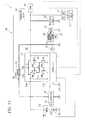
- the controller 14 sets the contactor 15 to be in a connecting state by setting the contactor relay 16 to ON. Thereby, as shown in FIG. 4 , the controller 14 connects each of the capacitor 11 and the battery 12 in parallel to the starter magnet switch 18 and the starter motor 20 that are connected in series. Then, the controller 14 drives the starter motor 20 by electric power supply from the capacitor 11 and the battery 12 and starts the internal combustion engine 22 using the driving force of the starter motor 20.
- the output voltage and the remaining capacity SOC of the capacitor 11 decreases due to electric power supply from the capacitor 11 to the starter motor 20.
- the controller 14 performs the operation of an I/S preparation charging mode M2.
- the controller 14 charges the capacitor 11 by electric power supply to the capacitor 11 from the generator 21 via the DC-DC converter 13 using the generated electric power output from the generator 21 that generates electric power by the drive power of the internal combustion engine 22 in a running state.
- electric power is supplied from the generator 21 to the electric load 23 and also is supplied from the generator 21 to the battery 12 corresponding to the state of the battery 12.
- the controller 14 sets the contactor 15 to be in a disconnecting state by setting the contactor relay 16 to OFF and sets the starter magnet switch 18 to be in a disconnecting state by setting the starter relay 19 to OFF.
- the controller 14 applies a current to the diode D and the resistance R and also applies a current to the third switching device SW3 in an ON state, the reactor L, and the first diode D1 in between the second input-output terminal 13b and the first input-output terminal 13a of the DC-DC converter 13.
- the controller 14 charges the capacitor 11 at least until the output voltage of the capacitor 11 reaches a predetermined I/S preparation voltage such that electric power required to restart the internal combustion engine 22 is stored in the capacitor 11 in preparation for execution of idle stopping.
- the predetermined I/S preparation voltage is, for example, an output voltage corresponding to the remaining capacity SOC of the capacitor 11 capable of performing electric power supply required for the electric load 23 and the like in the pause state of the internal combustion engine 22 over a predetermined period of time due to idle stopping.
- the controller 14 continues to perform the operation of the I/S preparation charging mode M2.
- the controller 14 switches the third switching device SW3 from the ON state to the OFF state and applies a current to the diode D and the resistance R in between the second input-output terminal 13b and the first input-output terminal 13a of the DC-DC converter 13. Thereby, the controller 14 maintains the output voltage of the capacitor 11 at the predetermined I/S preparation voltage.
- the controller 14 performs the operation of a regeneration charging mode M3.
- the controller 14 charges the capacitor 11 by electric power supply to the capacitor 11 from the generator 21 via the DC-DC converter 13 using the regenerated electric power output from the generator 21 when the vehicle 1 is decelerated or the like.
- electric power is supplied from the generator 21 to the electric load 23 and also is supplied from the generator 21 to the battery 12 corresponding to the state of the battery 12.
- the controller 14 converts kinetic energy of the vehicle body transmitted from drive wheels (not shown in the drawing) of the vehicle 1 into electric energy (regenerated energy) by the generator 21 and produces the regenerated electric power.
- the controller 14 sets the contactor 15 to be in a disconnecting state by setting the contactor relay 16 to OFF and sets the starter magnet switch 18 to be in a disconnecting state by setting the starter relay 19 to OFF.
- the controller 14 applies a current to the diode D and the resistance R and also applies a current to the third switching device SW3 in an ON state, the reactor L, and the first diode D1 in between the second input-output terminal 13b and the first input-output terminal 13a of the DC-DC converter 13.
- the controller 14 charges the capacitor 11 at least in a range in which the output voltage of the capacitor 11 is a predetermined upper-limit voltage or less.
- the controller 14 continues to perform the operation of the regeneration charging mode M3.
- the controller 14 switches the third switching device SW3 from the ON state to the OFF state and applies a current to the diode D and the resistance R in between the second input-output terminal 13b and the first input-output terminal 13a of the DC-DC converter 13. Thereby, the controller 14 maintains the output voltage of the capacitor 11 at the predetermined upper-limit voltage.
- the controller 14 performs the operation of a regeneration discharging mode M4.
- the controller 14 discharges the capacitor 11 by electric power supply from the capacitor 11 to the electric load 23 via the DC-DC converter 13 using the regenerated electric power stored in the capacitor 11 exceeding the predetermined I/S preparation voltage.
- the controller 14 sets the contactor 15 to be in a disconnecting state by setting the contactor relay 16 to OFF and sets the starter magnet switch 18 to be in a disconnecting state by setting the starter relay 19 to OFF.
- the controller 14 applies a current to the first switching device SW1 in an ON state, the reactor L, and the third diode D3 in between the first input-output terminal 13a and the second input-output terminal 13b of the DC-DC converter 13.
- the controller 14 discharges the capacitor 11 at least until the output voltage of the capacitor 11 reaches the predetermined I/S preparation voltage.
- the controller 14 stops electric power generation and regeneration of the generator 21 or sets the output voltage of the generator 21 to a voltage lower than a specified voltage at normal operations.
- the controller 14 performs the operation of an I/S electric power supply (capacitor) mode M5.
- I/S electric power supply (capacitor) mode M5 as shown in FIG. 10 , in the pause state of the internal combustion engine 22 due to idle stopping of the vehicle 1, the controller 14 discharges the capacitor 11 by electric power supply from the capacitor 11 to the electric load 23 via the DC-DC converter 13 using the electric power stored in the capacitor 11 exceeding a predetermined I/S lower-limit voltage.
- the controller 14 sets the contactor 15 to be in a disconnecting state by setting the contactor relay 16 to OFF and sets the starter magnet switch 18 to be in a disconnecting state by setting the starter relay 19 to OFF.
- the controller 14 applies a current to the first switching device SW1 in an ON state, the reactor L, and the third diode D3 in between the first input-output terminal 13a and the second input-output terminal 13b of the DC-DC converter 13.
- the controller 14 discharges the capacitor 11 at least until the output voltage of the capacitor 11 reaches the predetermined I/S lower-limit voltage while securing electric power required to restart the internal combustion engine 22 corresponding to a return request.
- the predetermined I/S lower-limit voltage is smaller than the I/S preparation voltage and is, for example, an output voltage corresponding to a remaining capacity SOC capable of performing appropriate electric power supply required to restart the internal combustion engine 22 in the pause state by the driving force of the starter motor 20.
- appropriate electric power supply by the capacitor 11 means that the capacitor 11 is discharged such that the output voltage of the capacitor 11 is not decreased to less than a predetermined minimum safeguard voltage. Therefore, as shown in FIG. 10 , the controller 14 is capable of charging the capacitor 11 by electric power supply to the capacitor 11 from the battery 12 via the diode D and the resistance R of the DC-DC converter 13 in addition to electric power supply to the electric load 23 from the battery 12.
- the controller 14 prevents the output voltage of the capacitor 11 from decreasing to a voltage less than the predetermined minimum safeguard voltage.
- the minimum safeguard voltage is smaller than the I/S lower-limit voltage and is, for example, an output voltage required to maintain the capacitor 11 in an adequate state.
- the controller 14 performs the operation of an I/S electric power supply (BATT) mode M6.
- I/S electric power supply (BATT) mode M6 as shown in FIG. 11 , in the pause state of the internal combustion engine 22 due to idle stopping of the vehicle 1, the controller 14 charges the capacitor 11 by electric power supply from the battery 12 to the capacitor 11 via the DC-DC converter 13 using electric power stored in the battery 12. Moreover, electric power is supplied from the battery 12 to the electric load 23.
- the controller 14 sets the contactor 15 to be in a disconnecting state by setting the contactor relay 16 to OFF and sets the starter magnet switch 18 to be in a disconnecting state by setting the starter relay 19 to OFF.
- the controller 14 switches the first switching device SW1 from the ON state to the OFF state and applies a current to the diode D and the resistance R in between the second input-output terminal 13b and the first input-output terminal 13a of the DC-DC converter 13. Thereby, the controller 14 maintains the output voltage of the capacitor 11 at the predetermined I/S lower-limit voltage and inhibits discharging from the capacitor 11 in which the minimum electric power required to restart the internal combustion engine 22 corresponding to a return request is secured.
- the controller 14 when the controller 14 receives a return request that requests to restart the internal combustion engine 22 in the pause state due to idle stopping, the controller 14 performs the operation of an ENG restarting mode M7.
- the controller 14 sets the contactor 15 to be in a disconnecting state by setting the contactor relay 16 to OFF and sets the starter magnet switch 18 to be in a connecting state by setting the starter relay 19 to ON.
- the controller 14 drives the starter motor 20 by electric power supply from only the capacitor 11 connected in parallel to the starter magnet switch 18 and the starter motor 20 that are connected in series and restarts the internal combustion engine 22 by the driving force of the starter motor 20.
- the controller 14 supplies electric power from the battery 12 to the electric load 23 and also charges the capacitor 11 by electric power supply from the battery 12 to the capacitor 11 via the DC-DC converter 13. Thereby, the controller 14 prevents the output voltage of the capacitor 11 from decreasing to less than the predetermined minimum safeguard voltage if the output voltage and the remaining capacity SOC of the capacitor 11 decreases due to electric power supplied from the capacitor 11 to the starter motor 20.
- the controller 14 sets the contactor 15 to be in a connecting state by setting the contactor relay 16 to ON. Thereby, the controller 14 drives the starter motor 20 by electric power supply from the capacitor 11 and the battery 12 and restarts the internal combustion engine 22 by the driving force of the starter motor 20.
- the controller 14 determines that it is impossible to restart the internal combustion engine 22 in the case that the rotation frequency of the internal combustion engine 22 (engine rotation frequency NE) detected by the rotation frequency sensor 27 is a predetermined rotation frequency or less after a predetermined length of time elapses since the beginning of restarting the internal combustion engine 22, in the case that a signal indicating a starting error of the internal combustion engine 22 output from the FI-ECU 17 is received, or the like.
- the controller 14 inhibits the next execution of idle stopping in the case that the internal combustion engine 22 is restarted by setting the contactor relay 16 to ON.
- the determination basis of inhibition of the next execution of idle stopping is not limited only to whether or not the internal combustion engine 22 is restarted by setting the contactor relay 16 to ON.
- the controller 14 may calculate the total number of times of the restarting and inhibit the next execution of idle stopping in the case that the total number of times is a predetermined number of times or more (for example, once or more).
- the controller 14 may inhibit the next execution of idle stopping in the case that the output voltage of the battery 12 decreases to a predetermined lower-limit voltage or less when the internal combustion engine 22 is restarted by setting the contactor relay 16 to ON.
- the controller 14 performs the operation of the I/S preparation charging mode M2 described above.
- the controller 14 performs the operation of a vehicle stopping-period mode M8 over a predetermined length of time since the ignition switch 24 is switched from ON to OFF.
- the controller 14 sets the contactor 15 to be in a disconnecting state by setting the contactor relay 16 to OFF and sets the starter magnet switch 18 to be in a disconnecting state by setting the starter relay 19 to OFF.
- the controller 14 discharges the capacitor 11 by electric power supply from the capacitor 11 to the battery 12 and the electric load 23 via the DC-DC converter 13 and suppresses degradation of the capacitor 11 in the stopping period of the vehicle 1.
- the controller 14 applies a current to the first switching device SW1 in an ON state, the reactor L, and the third diode D3 in between the first input-output terminal 13a and the second input-output terminal 13b of the DC-DC converter 13.
- the controller 14 charges the capacitor 11 by electric power supply from the battery 12 to the capacitor 11 via the diode D and the resistance R of the DC-DC converter 13 in addition to electric power supply from the battery 12 to the electric load 23.
- the controller 14 removes inhibition of the next execution of idle stopping that requires restarting of the internal combustion engine 22 by the driving of the starter motor 20 (namely, driving inhibition of the starter motor 20).
- the controller 14 performs failure detection of the contactor 15 by using the output voltage VC of the capacitor 11 detected by the first voltage sensor 25 and the output voltage VB of the battery 12 detected by the second voltage sensor 26.
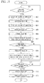
- step S01 shown in FIG. 15 the controller 14 determines whether or not the ignition switch 24 is switched from OFF to ON.
- step S01 In the case that this determination result is "No", the determination process of step S01 is repeatedly performed.
- step S02 the controller 14 detects the presence or absence of the ON failure of the contactor 15.
- the controller 14 determines whether or not the absolute value of the difference between the output voltage VC and the output voltage VB is a predetermined first threshold value or less over a predetermined length of time in a state where it is commanded to set the contactor 15 to be in a disconnecting state by setting the contactor relay 16 to OFF.
- this determination result is "Yes"
- the predetermined first threshold value is appropriately set according to the accuracy of the measurement device (first voltage sensor 25, second voltage sensor 26), the accuracy of the whole measurement system, measurement environments, or the like.
- the first threshold value can be 0.001VC, 0.002VC, 0.003VC, 0.004VC, 0.005VC, 0.006VC, 0.007VC, 0.008VC, 0.009VC, 0.01VC, 0.02VC, 0.03VC, 0.04VC, 0.05VC, 0.06VC, 0.07VC, 0.08VC, 0.09VC, or 0.1VC.
- the first threshold value can be 0.001VB, 0.002VB, 0.003VB, 0.004VB, 0.005VB, 0.006VB, 0.007VB, 0.008VB, 0.009VB, 0.01VB, 0.02VB, 0.03VB, 0.04VB, 0.05VB, 0.06VB, 0.07VB, 0.08VB, 0.09VB, or 0.1VB.
- the controller 14 determines that an ON failure of the contactor 15 occurs, the controller 14 notifies of the ON failure by a notification device (not shown in the drawing) that performs notification by display or sound output and inhibits execution of idle stopping.
- step S03 the controller 14 commands setting the contactor 15 to be in a connecting state by setting the contactor relay 16 to ON.
- step S04 the controller 14 detects the presence or absence of an OFF failure of the contactor 15.
- the controller 14 determines whether or not the output voltage VC and the output voltage VB change between before and after the controller 14 commands setting the contactor 15 to be in a connecting state.
- this determination result is "No"
- the controller 14 sets the output voltage of the capacitor 11 to equal to or less than a predetermined voltage which is lower than the output voltage of the battery 12 in order to suppress degradation of the capacitor 11.
- the controller 14 determines that the contactor 15 is normal.
- the controller 14 determines that an OFF failure of the contactor 15 occurs, the controller 14 notifies the driver of the vehicle 1 of the occurrence of an OFF failure by the notification device (not shown in the drawing) and inhibits execution of idle stopping. Moreover, the controller 14 sets driving of the starter motor 20 to be waiting until the temperature of the capacitor 11 increases to a predetermined temperature or more in order to enable the internal combustion engine 22 to start by electric power supply from only the capacitor 11 at the first-time start-up. Then, the controller 14 notifies the driver of the vehicle 1, by the notification device (not shown in the drawing), of that the internal combustion engine 22 is set to be waiting for starting.
- step S05 in the case that the contactor relay 16 is set to ON, the controller 14 sets the contactor 15 to be in a disconnecting state by switching the contactor relay 16 from ON to OFF.
- controller 14 performs failure detection of the contactor 15 and then performs the operation of the first-time start-up mode M1.
- step S06 shown in FIG. 15 the controller 14 sets the starter magnet switch 18 to be in a connecting state by setting the starter relay 19 to ON. Then, the pinion gear of the starter motor 20 is engaged with the ring gear of the internal combustion engine 22, and a state in which the driving force of the starter motor 20 is capable of being transmitted to the internal combustion engine 22 is set.
- step S07 the controller 14 drives the starter motor 20 by electric power supply from only the capacitor 11.
- step S08 the controller 14 determines whether or not a predetermined condition is established.
- the predetermined condition is, for example, that the output voltage VC of the capacitor 11 and the output voltage VB of the battery 12 are a predetermined first voltage or more, the output voltage VC of the capacitor 11 is a predetermined second voltage or less, and the rotation frequency of the internal combustion engine 22 (engine rotation frequency NE) detected by the rotation frequency sensor 27 is a predetermined rotation frequency (second threshold value) or less.
- the predetermined first voltage is a voltage required to prevent welding and wear of the contactor 15.
- the predetermined second voltage is a voltage that is allowed to be applied to the battery 12 during electric power supply from the capacitor 11 to the battery 12.
- step S09 the controller 14 sets the contactor 15 to be in a connecting state by setting the contactor relay 16 to ON.
- step S10 the controller 14 drives the starter motor 20 by electric power supplied from the capacitor 11 and the battery 12 and starts the internal combustion engine 22.
- step S 11 the controller 14 determines whether or not the states of the internal combustion engine 22 from initial ignition to perfect ignition are confirmed.
- step S11 In the case that this determination result is "No", the determination process of step S11 is repeatedly performed.
- the controller 14 determines that perfect ignition occurs in the case that the engine rotation frequency NE detected by the rotation frequency sensor 27 reaches a predetermined determination rotation frequency used to determine perfect ignition of the internal combustion engine 22.
- step S12 the controller 14 sets the starter magnet switch 18 to be in a disconnecting state by setting the starter relay 19 to OFF and stops the driving of the starter motor 20. Then, the engagement between the pinion gear of the starter motor 20 and the ring gear of the internal combustion engine 22 is removed, and power transmission between the starter motor 20 and the internal combustion engine 22 is disconnected.
- step S13 in the case that the contactor relay 16 is set to ON, the controller 14 sets the contactor 15 to be in a disconnecting state by switching the contactor relay 16 from ON to OFF and completes starting of the internal combustion engine 22, and the routine proceeds to END.
- the controller 14 performs the operation of the ENG restarting mode M7 in an idle stopping state of the vehicle 1.
- step S21 shown in FIG. 17 the controller 14 determines whether or not a return request that requests to restart the internal combustion engine 22 in a pause state due to idle stopping is received.
- step S21 In the case that this determination result is "No", the determination process of step S21 is repeatedly performed.
- the return request is, for example, output from the FI-ECU 17 in the case that the brake pedal operation by the driver is removed or the like.
- step S22 the controller 14 sets the starter magnet switch 18 to be in a connecting state by setting the starter relay 19 to ON. Then, the pinion gear of the starter motor 20 is engaged with the ring gear of the internal combustion engine 22, and a state in which the driving force of the starter motor 20 is capable of being transmitted to the internal combustion engine 22 is set.
- step S23 the controller 14 drives the starter motor 20 by electric power supply from only the capacitor 11.
- step S24 the controller 14 determines whether or not the output voltage VC of the capacitor 11 is a predetermined third voltage or more and the engine rotation frequency NE detected by the rotation frequency sensor 27 is greater than a predetermined rotation frequency after a predetermined length of time elapses since the beginning of restarting the internal combustion engine 22.
- the predetermined third voltage is a voltage required for a current that flows through the contactor 15 to be a predetermined upper-limit current or less in the case that the contactor 15 in a disconnecting state at this time is switched to a connecting state.
- step S25 the controller 14 determines whether or not the states of the internal combustion engine 22 from initial ignition to perfect ignition are confirmed.
- step S25 In the case that this determination result is "No", the determination process of step S25 is repeatedly performed.
- step S26 the controller 14 sets the starter magnet switch 18 to be in a disconnecting state by setting the starter relay 19 to OFF and stops the driving of the starter motor 20. Then, the engagement between the pinion gear of the starter motor 20 and the ring gear of the internal combustion engine 22 is removed, and power transmission between the starter motor 20 and the internal combustion engine 22 is disconnected. Thereby, the controller 14 completes starting of the internal combustion engine 22, and the routine proceeds to END.
- step S27 the controller 14 sets the starter magnet switch 18 to be in a disconnecting state by setting the starter relay 19 to OFF and stops driving of the starter motor 20. Then, the engagement between the pinion gear of the starter motor 20 and the ring gear of the internal combustion engine 22 is removed, and power transmission between the starter motor 20 and the internal combustion engine 22 is disconnected.
- the controller 14 stops the internal combustion engine 22.
- step S28 the controller 14 notifies the driver of the vehicle 1, by the notification device (not shown in the drawing), of that it is necessary to perform a predetermined operation (for example, a predetermined key operation, an ON operation of the ignition switch 24, or the like) in order to restart the internal combustion engine 22.
- a predetermined operation for example, a predetermined key operation, an ON operation of the ignition switch 24, or the like
- step S29 the controller 14 determines whether or not the predetermined operation is performed by the driver of the vehicle 1.
- step S29 is repeatedly performed.
- step S30 the controller 14 starts performing the operation similar to the first-time start-up mode M1.
- the starter magnet switch 18 is set to be in a connecting state by setting the starter relay 19 to ON.
- the pinion gear of the starter motor 20 is engaged with the ring gear of the internal combustion engine 22, and a state in which the driving force of the starter motor 20 is capable of being transmitted to the internal combustion engine 22 is set.
- step S31 the controller 14 drives the starter motor 20 by electric power supply from only the capacitor 11.
- step S32 the controller 14 determines whether or not the predetermined condition described above is established.
- step S32 In the case that this determination result is "No", the determination process of step S32 is repeatedly performed.
- step S33 the controller 14 sets the contactor 15 to be in a connecting state by setting the contactor relay 16 to ON.
- step S34 the controller 14 drives the starter motor 20 by electric power supplied from the capacitor 11 and the battery 12 and restarts the internal combustion engine 22.
- step S35 the controller 14 determines whether or not the states of the internal combustion engine 22 from initial ignition to perfect ignition are confirmed.
- step S36 it is determined that an abnormality of the internal combustion engine 22 occurs, and the routine proceeds to END.
- step S37 the controller 14 sets the starter magnet switch 18 to be in a disconnecting state by setting the starter relay 19 to OFF and stops the driving of the starter motor 20. Then, the engagement between the pinion gear of the starter motor 20 and the ring gear of the internal combustion engine 22 is removed, and power transmission between the starter motor 20 and the internal combustion engine 22 is disconnected.
- step S38 the controller 14 sets the contactor 15 to be in a disconnecting state by setting the contactor relay 16 to OFF and completes restarting of the internal combustion engine 22.
- step S39 the controller 14 commands inhibition of the next execution of idle stopping, and the routine proceeds to END.
- the controller 14 determines that an abnormality of the electric power supply circuit configured by the capacitor 11 and the battery 12 occurs and inhibits the next execution of idle stopping.
- the controller 14 changes (for example, increases) the predetermined I/S lower-limit voltage.
- the controller 14 inhibits execution of idle stopping.
- the controller 14 detects the presence or absence of an OFF failure of the contactor 15. At this time, the controller 14 commands that the contactor 15 is set to be in a connecting state by setting the contactor relay 16 to ON, and therefore, in the case that the contactor 15 is normal, it is possible to clean up the contact point of the contactor 15. Moreover, it is possible to increase the output voltage of the capacitor 11 by electric power supplied from the battery 12 to the capacitor 11, and it is possible to improve the starting performance and the toughness performance when the internal combustion engine 22 is started by electric power supplied from the capacitor 11 to the starter motor 20.
- the controller 14 sets driving of the starter motor 20 to be waiting until the temperature of the capacitor 11 increases to a predetermined temperature or more at the first-time start-up, and therefore it is possible to start the internal combustion engine 22 adequately by electric power supplied from the capacitor 11 to the starter motor 20.
- the controller 14 detects the presence or absence of an ON failure of the contactor 15 and, in the case that an ON failure occurs, inhibits execution of idle stopping, namely inhibits driving of the starter motor 20, it is possible to prevent the output voltage of the battery 12 from decreasing and to prevent electric power supply shortage in the electric load 23 as a variety of auxiliary machines to which electric power is supplied from the battery 12 from occurring.
- the controller 14 first drives the starter motor 20 by electric power supplied from only the capacitor 11 when the operation of the first-time start-up mode is performed, it is possible to prevent the output voltage of the battery 12 from decreasing and to prevent electric power supply shortage in the electric load 23 as a variety of auxiliary machines to which electric power is supplied from the battery 12 from occurring. For example, by preventing the controller 14 to which electric power is supplied from the battery 12 from being reset, it is possible to prevent the starting time when the internal combustion engine 22 is started from being long and to improve the starting performance and the toughness performance.
- the controller 14 connects the contactor 15 in the case that a predetermined condition is established in a state where the starter motor 20 is driven by electric power supplied from only the capacitor 11, it is possible to prevent the contactor 15 from being unnecessarily connected. Moreover, because the contactor 15 is connected in the case that electric power supplied from the capacitor 11 to the starter motor 20 is actually insufficient, it becomes possible to supply electric power from the battery 12 to the starter motor 20, and it is possible to appropriately start the internal combustion engine 22.
- the controller 14 stops the starter motor 20 and the internal combustion engine 22 and then connects the contactor 15. Thereby, the controller 14 can prevent the output voltage of the battery 12 from decreasing by supplying electric power from the battery 12 to the capacitor 11 during the driving of the vehicle 1.
- the controller 14 inhibits execution of the idle stopping in a state where restarting of the internal combustion engine 22 from the idle stopping is not allowed, namely in a state where it is necessary to connect the contactor 15 in order to restart the internal combustion engine 22 and therefore there is a possibility that the output voltage of the battery 12 decreases. Thereby it is possible to appropriately keep the vehicle 1 being capable of being driven.
- the DC-DC converter 13 is an H-bridge step-up/step-down DC-DC converter, but the converter is not limited thereto.
- the converter may be a step-up/step-down DC-DC converter having another configuration.
- the contactor 15 may be another switch.
- the controller 14 sets the contactor 15 to be in a connecting state and drives the starter motor 20 by electric power supplied from the capacitor 11 and the battery 12.
- the controller 14 may inhibit driving of the starter motor 20 and also charge the capacitor 11 by electric power supplied from the battery 12 to the capacitor 11 until the output voltage of the capacitor 11 reaches a voltage which is capable of starting the internal combustion engine 22.
- a control unit (14) of a vehicle electric power supply apparatus (10) controls an opening and closing unit (16) to set a switch (15) to an OFF state and a voltage detection unit (26, 25) to detect an output voltage (VB) of a first power source (12) and an output voltage (VC) of a second power source (11) when a second electric load (20) is to be driven, and the control unit inhibits driving of the second electric load when the absolute value of the difference between the output voltage of the first power source and the output voltage of the second power source detected by the voltage detection unit is a predetermined first threshold value or less over a predetermined length of time.
Landscapes
- Engineering & Computer Science (AREA)
- Mechanical Engineering (AREA)
- Chemical & Material Sciences (AREA)
- Combustion & Propulsion (AREA)
- General Engineering & Computer Science (AREA)
- Power Engineering (AREA)
- Transportation (AREA)
- Life Sciences & Earth Sciences (AREA)
- Sustainable Development (AREA)
- Sustainable Energy (AREA)
- Charge And Discharge Circuits For Batteries Or The Like (AREA)
- Control Of Vehicle Engines Or Engines For Specific Uses (AREA)
- Control Of Eletrric Generators (AREA)
- Control Of Charge By Means Of Generators (AREA)
Applications Claiming Priority (2)
| Application Number | Priority Date | Filing Date | Title |
|---|---|---|---|
| JP2013138228A JP5855608B2 (ja) | 2013-07-01 | 2013-07-01 | 車両用電源装置 |
| JP2013138229A JP5859490B2 (ja) | 2013-07-01 | 2013-07-01 | 車両用電源装置 |
Publications (2)
| Publication Number | Publication Date |
|---|---|
| EP2821269A2 true EP2821269A2 (fr) | 2015-01-07 |
| EP2821269A3 EP2821269A3 (fr) | 2015-12-30 |
Family
ID=50981190
Family Applications (1)
| Application Number | Title | Priority Date | Filing Date |
|---|---|---|---|
| EP14174306.2A Ceased EP2821269A3 (fr) | 2013-07-01 | 2014-06-26 | Appareil d'alimentation électrique de véhicule, pour un démarreur/générateur combiné |
Country Status (3)
| Country | Link |
|---|---|
| US (1) | US9458813B2 (fr) |
| EP (1) | EP2821269A3 (fr) |
| CN (1) | CN104276044B (fr) |
Cited By (1)
| Publication number | Priority date | Publication date | Assignee | Title |
|---|---|---|---|---|
| EP2821289A1 (fr) * | 2013-07-02 | 2015-01-07 | Honda Motor Co., Ltd. | Dispositif d'alimentation électrique de véhicule |
Families Citing this family (26)
| Publication number | Priority date | Publication date | Assignee | Title |
|---|---|---|---|---|
| JP5941019B2 (ja) * | 2013-07-02 | 2016-06-29 | 本田技研工業株式会社 | 車両用電源装置 |
| JP2015209058A (ja) * | 2014-04-25 | 2015-11-24 | オムロンオートモーティブエレクトロニクス株式会社 | 電源装置 |
| JP2015217920A (ja) * | 2014-05-21 | 2015-12-07 | オムロンオートモーティブエレクトロニクス株式会社 | 車両用電源装置、車両用回生システム |
| JP2015217919A (ja) * | 2014-05-21 | 2015-12-07 | オムロンオートモーティブエレクトロニクス株式会社 | 車両用電源装置、車両用回生システム |
| US9776635B2 (en) * | 2015-02-09 | 2017-10-03 | Ford Global Technologies, Llc | Apparatus and method to maximize vehicle functionality and fuel economy with improved drivability during engine auto stop-start operations |
| US10026238B2 (en) | 2015-07-15 | 2018-07-17 | GM Global Technology Operations LLC | System and method for converting two diagnostic states of a controller to three diagnostic states |
| US10060985B2 (en) | 2015-07-15 | 2018-08-28 | GM Global Technology Operations LLC | System and method for monitoring temperatures of components of an ultra-capacitor system used with an auto start/stop system |
| US10202958B2 (en) * | 2015-07-15 | 2019-02-12 | GM Global Technology Operations LLC | System and method for controlling ultra-capacitor charge and discharge in vehicles with auto start/stop systems |
| US9923470B2 (en) * | 2015-09-18 | 2018-03-20 | Lear Corporation | High voltage pre-charge system |
| GB2537274B (en) * | 2015-10-16 | 2018-02-14 | Ford Global Tech Llc | A vehicle electrical system |
| US10343545B2 (en) * | 2016-01-15 | 2019-07-09 | Trumpet Holdings, Inc. | Systems and methods for separating batteries |
| JP6455486B2 (ja) * | 2016-06-07 | 2019-01-23 | トヨタ自動車株式会社 | 電源システム |
| JP6825250B2 (ja) * | 2016-07-07 | 2021-02-03 | 株式会社デンソー | 車載システム |
| JP6642470B2 (ja) * | 2017-02-02 | 2020-02-05 | 株式会社デンソー | 電源制御装置、電池パック、および、電源システム |
| CN106904077B (zh) * | 2017-03-23 | 2019-04-09 | 深圳腾势新能源汽车有限公司 | 一种电动汽车电机控制方法和系统 |
| KR102417380B1 (ko) * | 2017-04-12 | 2022-07-06 | 현대자동차주식회사 | 엔진 시동 시퀀스 제어 장치 및 방법 |
| CN109995240A (zh) | 2018-01-02 | 2019-07-09 | 通用电气公司 | 电源转换器及电源转换方法 |
| CN108556766A (zh) * | 2018-01-18 | 2018-09-21 | 安徽三弟电子科技有限责任公司 | 车载供电电源的自动供断电的方法及其控制系统 |
| JP7042425B2 (ja) * | 2018-12-11 | 2022-03-28 | 株式会社オートネットワーク技術研究所 | 制御装置及び故障判定方法 |
| WO2020167755A1 (fr) * | 2019-02-15 | 2020-08-20 | Kold-Ban International, Ltd. | Système de démarrage supplémentaire |
| KR102757855B1 (ko) * | 2019-06-21 | 2025-01-20 | 현대자동차주식회사 | 하이브리드 차량의 엔진 스타트 시스템 및 그 제어 방법 |
| CN113895373A (zh) * | 2020-07-06 | 2022-01-07 | 威马智慧出行科技(上海)有限公司 | 电动汽车高压附件的能量管理系统及其方法、智能汽车 |
| CN113183898B (zh) * | 2021-05-06 | 2023-05-12 | 重庆长安汽车股份有限公司 | 防止暗电流过大造成亏电的装置、方法及车辆 |
| JP7616121B2 (ja) | 2022-02-25 | 2025-01-17 | トヨタ自動車株式会社 | ハイブリッド車両の制御装置 |
| JP7632388B2 (ja) | 2022-05-25 | 2025-02-19 | トヨタ自動車株式会社 | ハイブリッド車両の制御装置 |
| CN117922461A (zh) * | 2022-10-14 | 2024-04-26 | 神基科技股份有限公司 | 车辆电源供应回路监控系统及车辆电源供应回路监控方法 |
Citations (2)
| Publication number | Priority date | Publication date | Assignee | Title |
|---|---|---|---|---|
| JP2010195336A (ja) | 2009-02-27 | 2010-09-09 | Panasonic Corp | 車両用電源装置 |
| DE102012216098A1 (de) * | 2011-09-13 | 2013-03-14 | Ford Global Technologies, Llc | Verfahren zum Steuern eines Brennkraftmaschinen-Stopp/Start-Systems |
Family Cites Families (30)
| Publication number | Priority date | Publication date | Assignee | Title |
|---|---|---|---|---|
| JP2001055941A (ja) * | 1999-08-16 | 2001-02-27 | Honda Motor Co Ltd | エンジン自動始動停止制御装置 |
| US6481404B1 (en) * | 2001-06-12 | 2002-11-19 | Ford Global Technologies, Inc. | Vehicle starting method and system |
| JP3958593B2 (ja) * | 2002-01-29 | 2007-08-15 | 三菱電機株式会社 | 車両用電源装置 |
| EP1424494A1 (fr) * | 2002-11-27 | 2004-06-02 | Continental ISAD Electronic Systems GmbH & Co. oHG | Dispositif de propulsion hybride et méthode pour l'application commune d'un couple de propulsion |
| EP1595748B1 (fr) * | 2003-02-17 | 2012-09-12 | Denso Corporation | Systeme d'alimentation de puissance pour véhicule |
| JP3972906B2 (ja) | 2003-04-09 | 2007-09-05 | 株式会社デンソー | 車両用電源システム |
| JP2004308524A (ja) * | 2003-04-04 | 2004-11-04 | Suzuki Motor Corp | 自動遠心クラッチを有する車両のエンジン制御装置 |
| US7243630B2 (en) * | 2004-03-08 | 2007-07-17 | Bz Products, Inc. | Foot controlled engine start and stop system for conversion of an off-road utility vehicle for use as a golf cart |
| JP2006029142A (ja) | 2004-07-13 | 2006-02-02 | Toyota Motor Corp | 車両のエンジン始動制御装置 |
| FR2875557B1 (fr) | 2004-09-23 | 2006-11-24 | Valeo Equip Electr Moteur | Procede de commande d'une machine electrique tournante |
| DE102004062938A1 (de) | 2004-12-28 | 2006-07-13 | Volkswagen Ag | Verfahren und Vorrichtung zum Betreiben eines Hybridenergiespeichers in einem Fahrzeug mit einem Hybridantriebsystem |
| JP2007113460A (ja) * | 2005-10-19 | 2007-05-10 | Nissan Motor Co Ltd | エンジン始動制御装置およびエンジン始動制御方法。 |
| DE102005060129A1 (de) | 2005-12-16 | 2007-06-21 | Bayerische Motoren Werke Ag | Verfahren zum Steuern eines Bordnetzes für ein Kraftfahrzeug |
| US9308899B2 (en) * | 2006-01-26 | 2016-04-12 | Fuji Jukogyo Kabushiki Kaisha | Vehicle control system |
| JP4186085B2 (ja) * | 2007-03-02 | 2008-11-26 | 三菱自動車工業株式会社 | エンジン始動制御装置 |
| US7573151B2 (en) * | 2007-10-11 | 2009-08-11 | Lear Corporation | Dual energy-storage for a vehicle system |
| US7963264B2 (en) * | 2008-06-25 | 2011-06-21 | GM Global Technology Operations LLC | Engine cranking system and method |
| JP5282876B2 (ja) | 2008-09-26 | 2013-09-04 | マツダ株式会社 | 車両用電源装置 |
| JP2011004556A (ja) * | 2009-06-22 | 2011-01-06 | Mitsubishi Electric Corp | 車両用電源装置 |
| EP2594437A4 (fr) * | 2010-07-15 | 2014-11-19 | Panasonic Corp | Dispositif d'alimentation électrique pour véhicule |
| JP5402901B2 (ja) * | 2010-09-30 | 2014-01-29 | 株式会社デンソー | エンジン制御装置 |
| WO2012063309A1 (fr) * | 2010-11-08 | 2012-05-18 | トヨタ自動車株式会社 | Dispositif de démarrage de moteur à combustion |
| JP5817136B2 (ja) * | 2011-02-16 | 2015-11-18 | 日産自動車株式会社 | エンジンの始動装置の保護装置 |
| JP5019083B1 (ja) * | 2011-06-09 | 2012-09-05 | 三菱自動車工業株式会社 | 車両の制御装置 |
| EP2562910B1 (fr) | 2011-08-25 | 2018-07-11 | Volvo Car Corporation | Système à plusieurs batteries pour démarrage/arrêt |
| JP5802502B2 (ja) * | 2011-09-27 | 2015-10-28 | 新電元工業株式会社 | 故障検出装置および方法 |
| JP2013091477A (ja) | 2011-10-27 | 2013-05-16 | Autonetworks Technologies Ltd | 車両用電源装置 |
| JP5312557B2 (ja) * | 2011-11-10 | 2013-10-09 | 三菱電機株式会社 | 電源管理装置、電源管理方法、および、電源管理システム |
| JP5442042B2 (ja) * | 2012-01-18 | 2014-03-12 | 三菱電機株式会社 | エンジン始動装置およびエンジン始動方法 |
| JP5941019B2 (ja) * | 2013-07-02 | 2016-06-29 | 本田技研工業株式会社 | 車両用電源装置 |
-
2014
- 2014-06-16 CN CN201410268220.2A patent/CN104276044B/zh not_active Expired - Fee Related
- 2014-06-26 US US14/315,432 patent/US9458813B2/en not_active Expired - Fee Related
- 2014-06-26 EP EP14174306.2A patent/EP2821269A3/fr not_active Ceased
Patent Citations (2)
| Publication number | Priority date | Publication date | Assignee | Title |
|---|---|---|---|---|
| JP2010195336A (ja) | 2009-02-27 | 2010-09-09 | Panasonic Corp | 車両用電源装置 |
| DE102012216098A1 (de) * | 2011-09-13 | 2013-03-14 | Ford Global Technologies, Llc | Verfahren zum Steuern eines Brennkraftmaschinen-Stopp/Start-Systems |
Cited By (1)
| Publication number | Priority date | Publication date | Assignee | Title |
|---|---|---|---|---|
| EP2821289A1 (fr) * | 2013-07-02 | 2015-01-07 | Honda Motor Co., Ltd. | Dispositif d'alimentation électrique de véhicule |
Also Published As
| Publication number | Publication date |
|---|---|
| CN104276044B (zh) | 2017-11-03 |
| CN104276044A (zh) | 2015-01-14 |
| EP2821269A3 (fr) | 2015-12-30 |
| US9458813B2 (en) | 2016-10-04 |
| US20150001857A1 (en) | 2015-01-01 |
Similar Documents
| Publication | Publication Date | Title |
|---|---|---|
| US9458813B2 (en) | Vehicle electric power supply apparatus | |
| US9688224B2 (en) | Vehicle electric power supply apparatus | |
| EP2821309B1 (fr) | Dispositif d'alimentation électrique de véhicule | |
| JP5677362B2 (ja) | 電源劣化判定装置 | |
| EP2821289A1 (fr) | Dispositif d'alimentation électrique de véhicule | |
| US10536005B2 (en) | Power supply control apparatus | |
| US9982647B2 (en) | Engine start system | |
| US20180233943A1 (en) | Power supply system for vehicle | |
| EP2907716A2 (fr) | Procédé permettant d'améliorer le fonctionnement d'un moteur | |
| JP6015171B2 (ja) | アイドルストップ付きエンジン搭載車の電源装置 | |
| EP2808521A1 (fr) | Dispositif de commande de véhicule, véhicule, et procédé de commande de véhicule | |
| KR101323916B1 (ko) | 차량의 초기 기동 장치 및 방법 | |
| JP5859490B2 (ja) | 車両用電源装置 | |
| JP5855608B2 (ja) | 車両用電源装置 | |
| CN108258783B (zh) | 电源控制系统及电源控制方法 | |
| JP5852932B2 (ja) | エンジン再始動制御装置 | |
| WO2015159876A1 (fr) | Dispositif de commande pour véhicules |
Legal Events
| Date | Code | Title | Description |
|---|---|---|---|
| PUAI | Public reference made under article 153(3) epc to a published international application that has entered the european phase |
Free format text: ORIGINAL CODE: 0009012 |
|
| 17P | Request for examination filed |
Effective date: 20140626 |
|
| AK | Designated contracting states |
Kind code of ref document: A2 Designated state(s): AL AT BE BG CH CY CZ DE DK EE ES FI FR GB GR HR HU IE IS IT LI LT LU LV MC MK MT NL NO PL PT RO RS SE SI SK SM TR |
|
| AX | Request for extension of the european patent |
Extension state: BA ME |
|
| RIC1 | Information provided on ipc code assigned before grant |
Ipc: B60L 11/18 20060101ALI20150722BHEP Ipc: B60W 20/00 20060101ALI20150722BHEP Ipc: B60K 5/00 20060101AFI20150722BHEP Ipc: F02N 11/04 20060101ALI20150722BHEP Ipc: B60L 7/10 20060101ALI20150722BHEP Ipc: F02N 11/08 20060101ALI20150722BHEP Ipc: F02N 11/10 20060101ALI20150722BHEP Ipc: B60R 16/03 20060101ALI20150722BHEP |
|
| PUAL | Search report despatched |
Free format text: ORIGINAL CODE: 0009013 |
|
| AK | Designated contracting states |
Kind code of ref document: A3 Designated state(s): AL AT BE BG CH CY CZ DE DK EE ES FI FR GB GR HR HU IE IS IT LI LT LU LV MC MK MT NL NO PL PT RO RS SE SI SK SM TR |
|
| AX | Request for extension of the european patent |
Extension state: BA ME |
|
| RIC1 | Information provided on ipc code assigned before grant |
Ipc: F02N 11/10 20060101ALI20151126BHEP Ipc: F02N 11/08 20060101ALI20151126BHEP Ipc: F02N 11/04 20060101ALI20151126BHEP Ipc: B60L 11/18 20060101ALI20151126BHEP Ipc: B60R 16/03 20060101ALI20151126BHEP Ipc: B60K 5/00 20060101AFI20151126BHEP Ipc: B60W 20/00 20060101ALI20151126BHEP Ipc: B60L 7/10 20060101ALI20151126BHEP |
|
| 17Q | First examination report despatched |
Effective date: 20161027 |
|
| 18R | Application refused |
Effective date: 20171126 |