EP2821730A2 - Pièce de raccordement et ensemble de montage - Google Patents
Pièce de raccordement et ensemble de montage Download PDFInfo
- Publication number
- EP2821730A2 EP2821730A2 EP14171302.4A EP14171302A EP2821730A2 EP 2821730 A2 EP2821730 A2 EP 2821730A2 EP 14171302 A EP14171302 A EP 14171302A EP 2821730 A2 EP2821730 A2 EP 2821730A2
- Authority
- EP
- European Patent Office
- Prior art keywords
- connecting piece
- flow restrictor
- sieve
- outlet
- screen
- Prior art date
- Legal status (The legal status is an assumption and is not a legal conclusion. Google has not performed a legal analysis and makes no representation as to the accuracy of the status listed.)
- Granted
Links
- 210000002105 tongue Anatomy 0.000 claims abstract description 22
- 238000007789 sealing Methods 0.000 claims abstract description 21
- 210000002445 nipple Anatomy 0.000 claims abstract description 13
- 238000009434 installation Methods 0.000 claims abstract description 9
- XLYOFNOQVPJJNP-UHFFFAOYSA-N water Substances O XLYOFNOQVPJJNP-UHFFFAOYSA-N 0.000 claims description 33
- 239000012530 fluid Substances 0.000 claims description 23
- 238000004806 packaging method and process Methods 0.000 claims description 16
- 239000000463 material Substances 0.000 claims description 8
- 229930040373 Paraformaldehyde Natural products 0.000 claims description 7
- 229920003023 plastic Polymers 0.000 claims description 7
- 229920006324 polyoxymethylene Polymers 0.000 claims description 7
- 239000004033 plastic Substances 0.000 claims description 6
- -1 polyoxymethylene Polymers 0.000 claims description 4
- 239000003566 sealing material Substances 0.000 claims description 4
- 230000008961 swelling Effects 0.000 claims description 3
- 229920001169 thermoplastic Polymers 0.000 claims 1
- 238000012423 maintenance Methods 0.000 abstract description 5
- 238000004519 manufacturing process Methods 0.000 description 11
- 239000000853 adhesive Substances 0.000 description 6
- 238000011161 development Methods 0.000 description 5
- 239000011888 foil Substances 0.000 description 5
- 230000001070 adhesive effect Effects 0.000 description 4
- 230000000694 effects Effects 0.000 description 3
- 230000002349 favourable effect Effects 0.000 description 3
- 238000005266 casting Methods 0.000 description 2
- 150000001875 compounds Chemical class 0.000 description 2
- 238000013461 design Methods 0.000 description 2
- 238000003780 insertion Methods 0.000 description 2
- 230000037431 insertion Effects 0.000 description 2
- 239000002184 metal Substances 0.000 description 2
- 238000000034 method Methods 0.000 description 2
- 239000005060 rubber Substances 0.000 description 2
- 238000005245 sintering Methods 0.000 description 2
- 125000006850 spacer group Chemical group 0.000 description 2
- 229910001369 Brass Inorganic materials 0.000 description 1
- 244000025254 Cannabis sativa Species 0.000 description 1
- 235000012766 Cannabis sativa ssp. sativa var. sativa Nutrition 0.000 description 1
- 235000012765 Cannabis sativa ssp. sativa var. spontanea Nutrition 0.000 description 1
- 208000034656 Contusions Diseases 0.000 description 1
- 240000007817 Olea europaea Species 0.000 description 1
- 230000006978 adaptation Effects 0.000 description 1
- 230000000903 blocking effect Effects 0.000 description 1
- 239000010951 brass Substances 0.000 description 1
- 235000009120 camo Nutrition 0.000 description 1
- 235000005607 chanvre indien Nutrition 0.000 description 1
- 238000004140 cleaning Methods 0.000 description 1
- 230000006835 compression Effects 0.000 description 1
- 238000007906 compression Methods 0.000 description 1
- 238000011109 contamination Methods 0.000 description 1
- 238000005516 engineering process Methods 0.000 description 1
- 239000011487 hemp Substances 0.000 description 1
- 238000002347 injection Methods 0.000 description 1
- 239000007924 injection Substances 0.000 description 1
- 230000010354 integration Effects 0.000 description 1
- 230000007257 malfunction Effects 0.000 description 1
- 229910001092 metal group alloy Inorganic materials 0.000 description 1
- 239000002991 molded plastic Substances 0.000 description 1
- 239000002245 particle Substances 0.000 description 1
- 230000035515 penetration Effects 0.000 description 1
- 229920000642 polymer Polymers 0.000 description 1
- 230000003134 recirculating effect Effects 0.000 description 1
- 230000000717 retained effect Effects 0.000 description 1
- 239000004576 sand Substances 0.000 description 1
- 239000000565 sealant Substances 0.000 description 1
- 238000003860 storage Methods 0.000 description 1
- 239000012815 thermoplastic material Substances 0.000 description 1
Images


Classifications
-
- B—PERFORMING OPERATIONS; TRANSPORTING
- B01—PHYSICAL OR CHEMICAL PROCESSES OR APPARATUS IN GENERAL
- B01D—SEPARATION
- B01D35/00—Filtering devices having features not specifically covered by groups B01D24/00 - B01D33/00, or for applications not specifically covered by groups B01D24/00 - B01D33/00; Auxiliary devices for filtration; Filter housing constructions
- B01D35/02—Filters adapted for location in special places, e.g. pipe-lines, pumps, stop-cocks
-
- F—MECHANICAL ENGINEERING; LIGHTING; HEATING; WEAPONS; BLASTING
- F24—HEATING; RANGES; VENTILATING
- F24D—DOMESTIC- OR SPACE-HEATING SYSTEMS, e.g. CENTRAL HEATING SYSTEMS; DOMESTIC HOT-WATER SUPPLY SYSTEMS; ELEMENTS OR COMPONENTS THEREFOR
- F24D3/00—Hot-water central heating systems
- F24D3/10—Feed-line arrangements, e.g. providing for heat-accumulator tanks, expansion tanks ; Hydraulic components of a central heating system
- F24D3/1083—Filling valves or arrangements for filling
-
- F—MECHANICAL ENGINEERING; LIGHTING; HEATING; WEAPONS; BLASTING
- F24—HEATING; RANGES; VENTILATING
- F24H—FLUID HEATERS, e.g. WATER OR AIR HEATERS, HAVING HEAT-GENERATING MEANS, e.g. HEAT PUMPS, IN GENERAL
- F24H9/00—Details
- F24H9/12—Arrangements for connecting heaters to circulation pipes
- F24H9/13—Arrangements for connecting heaters to circulation pipes for water heaters
- F24H9/139—Continuous flow heaters
-
- A—HUMAN NECESSITIES
- A47—FURNITURE; DOMESTIC ARTICLES OR APPLIANCES; COFFEE MILLS; SPICE MILLS; SUCTION CLEANERS IN GENERAL
- A47L—DOMESTIC WASHING OR CLEANING; SUCTION CLEANERS IN GENERAL
- A47L15/00—Washing or rinsing machines for crockery or tableware
- A47L15/42—Details
- A47L15/4202—Water filter means or strainers
-
- A—HUMAN NECESSITIES
- A47—FURNITURE; DOMESTIC ARTICLES OR APPLIANCES; COFFEE MILLS; SPICE MILLS; SUCTION CLEANERS IN GENERAL
- A47L—DOMESTIC WASHING OR CLEANING; SUCTION CLEANERS IN GENERAL
- A47L15/00—Washing or rinsing machines for crockery or tableware
- A47L15/42—Details
- A47L15/4214—Water supply, recirculation or discharge arrangements; Devices therefor
- A47L15/4217—Fittings for water supply, e.g. valves or plumbing means to connect to cold or warm water lines, aquastops
Definitions
- the invention relates first to a connector for connecting a household appliance, in particular a water heater, with a fluid-carrying wall nipple, wherein the connector has an inlet and outlet ports, which are connected by a central portion with a shut-off device, in particular a ball valve, wherein the connecting piece can be screwed by means of the inlet nozzle to the wall nipple and a flange of a feed pipe of the household appliance by means of a screw-on the outlet nozzle union nut is connected to this.
- a shut-off device in particular a ball valve
- the invention relates to a mounting kit for a household appliance, in particular a water heater, comprising at least one connector and other components required for installation of the connector.
- Household appliances such as water heater, hot water tank or the like, are usually connected by means of fittings to wall outlets of the domestic cold water network.
- sieves and flow restrictors are often placed in the cold water supply.
- the flow restrictor adjusts for localized water pressure, whereas the strainer prevents contamination of the flow heater with foreign matter and malfunctions.
- a cross-branching nozzle is provided between an inlet and a drain for the fluid, in which a substantially hollow cylindrical sieve is received.
- This screen is made of polyoxymethylene (POM) and has a lateral receptacle into which a flow restrictor can be inserted and which can be closed by means of a hinged lid on the screen after insertion of the flow restrictor.
- the sieve and the lid are integrally injection molded from a plastic material, the sieve can be used only in the proper mounting position in the cross neck and fix, the cross-neck is sealed at the same time through the sieve upwards.
- a water outlet runs in this case at a right angle to a water inlet and with the help of a roller-shaped shut-off valve, the water inlet can be closed, whereby maintenance is simplified.
- the flow restrictor is received between the strainer and an approximately cup-shaped plug, the plug being screwed into the wall of the water channel and sealed against it with an O-ring.
- the sieve is in turn connected by means of a snap-on or snap connection with a lower end portion of the plug and arranged in the flow direction in the water channel.
- the strainer, the flow restrictor and the plug are each made with a suitable plastic material.
- a closable with a cap cross-piece extends the applications and can, for. B. be used as an inlet for a substructure fitting.
- a disadvantage of this known fluid channel device is the complex spatial design, which can be produced only by casting or sintering, resulting in comparatively high production costs. Furthermore, an additional, increasing the manufacturing cost housing opening for the integration of the screen and the flow restrictor is provided, which must also be sealed by a plug with a polymer O-ring.
- the object of the invention is first of all to specify an easy-to-install and serviceable connecting piece with a largely leak-free flow restrictor for connecting a household appliance to a fluid-dispensing wall outlet. Further, it is an object of the invention to provide a manufacturing technology easily manufactured mounting kit, which contains the connector, together with other components, for particularly simple installation of the connector.
- a sieve and a flow restrictor are accommodated in a seat of the outlet nozzle, wherein the sieve is latched by at least two locking tongues with the seat of the outlet and between the flange and an end face of the outlet nozzle, a sealing ring is arranged, are all essential components of the connector , in particular the screen, the flow restrictor and the sealing ring, summarized spatially compact behind the obturator in the region of the outlet downstream. Due to the locking tongues the sieve is captive or captive included in the seat of the outlet and therefore can be used by the manufacturer in the connector (mounted) and delivered together with this as a unit (sg installation kit).
- the inlet port, the outlet port and the obturator each have an approximately tubular geometry for the passage of the fluid and are each formed centrally to a longitudinal center axis, ie said components form at least completely open obturator a continuous, hollow cylindrical fluid channel with an ideally constant inner diameter.
- the connector of the invention can be integrated to save space in a flow heater even in confined space conditions.
- the screen with a thermoplastic material in particular polyoxymethylene, are formed.
- a particularly cost-effective production of the screen is possible in comparison to a metal mesh with an integrally molded plastic flange.
- the sealing ring is formed with a fluid-swelling paper sealing material and / or with a plastic material.
- a fluid-swelling paper sealing material preferably swellable, z. B. Centellen ® formed
- sealing ring is - regardless of the torque of a user - always given a sufficient sealing effect, so that in particular no leakage currents occur in the flow limiter.
- the seat in the outlet nozzle is approximately cylindrical and has an annular groove into which the at least two radially outwardly splayed locking tongues of the screen are at least partially positively insertable.
- the sieve is firmly latching or captive received in the seat of the outlet, so that it can not be lost during assembly.
- the locking tongues is also ensured that the sieve can be used by a user only in the correct position in the seat of the outlet nozzle and mounting errors are reliably avoided (see below mounting error protection).
- the seat can be manufactured easily and cost-optimally realized by a bore.
- a total length of sieve and flow restrictor is less than or equal to a depth of the seat in the outlet.
- the screen has a fluid-tight and substantially hollow-cylindrical jacket, on whose first end section pointing in the direction of the obturator, a transverse web is formed.
- a transverse web is formed between the tubular shell and the seat in the outlet nozzle given.
- the transverse web preferably extends over the full (inner) diameter of the jacket transversely to its longitudinal axis or the longitudinal center axis of the connecting piece.
- the flow restrictor is approximately disc-shaped and has a circumferential recession, which points in the direction of the obturator. As a result, a centering of the flow restrictor is given.
- the recess of the flow restrictor is received in a form-fitting manner at least partially on a second end section of the sieve.
- the flow limiter is centered and at the same time reliably held on the sieve with the union nut not yet screwed on.
- Sometimes. may be provided between the flow restrictor and the screen a slight press fit and / or a lock to increase the reliability of the seat yet. Nevertheless, the flow restrictor can be easily z. B. replace another flow restrictor with a higher or lower flow value.
- a flow restrictor suitable for a specific type of continuous flow heater having a certain coefficient of performance may be factory-set in the screen at the factory, with the user visually adjusting the preset flow value, e.g. B. on the color is pointed out.
- a projection with a rectangular cross-sectional geometry is formed centrally on the transverse web of the screen. This allows the sieve for cleaning purposes z. B. simply by means of a pair of needle nose pliers or the like and take out of the outlet nozzle against the locking action of the locking tongues.
- an active surface of the screen on two mutually V-shaped screen surfaces which emanate from diametrically opposite portions of the first end portion of the shell and run together in a common apex line in the region of the crosspiece.
- the effective area of the screen surface is increased and the filter effect is optimized.
- V-shaped or saddle-roof-shaped embodiment of the effective surface of the screen this can have any three-dimensional geometry.
- the spatial design of the effective area of the screen can also correspond to that of a parabola rotated once about its vertical axis.
- the object of the invention is achieved by a mounting kit according to claim 11, according to which the at least one connector is included in a household appliance enclosed packaging, in particular a transparent foil bag, and in the region of an outside of the package at least one additional packaging, in particular at least one Sticker, is provided for fixing the position of at least one flow restrictor for the connector on the packaging.
- a mounting kit according to claim 11 according to which the at least one connector is included in a household appliance enclosed packaging, in particular a transparent foil bag, and in the region of an outside of the package at least one additional packaging, in particular at least one Sticker, is provided for fixing the position of at least one flow restrictor for the connector on the packaging.
- At least one flow restrictor attached by preferably by means of the sticker at least one flow restrictor on the outside of the foil bag of the (base) mounting kit glued or otherwise attached to this.
- the optional attachment of the outer side for this purpose at least partially transparent and on the back or one-sided adhesive sticker on the foil bag of the mounting kit is easy and inexpensive to integrate into the production process of an existing production line.
- the installer can choose from the different flow rate restrictors included in the additional packaging and insert the appropriate one into the fitting.
- the attached flow restrictors are also color-coded to facilitate selection for the installer. For example, a flow restrictor for an electric heater power of a 24 kW instantaneous water heater to be installed is coded red, while a 12 kW flow restrictor is coded orange. More occurring in practice intermediate power of 18 kW and 21 kW can z. B. be encrypted in olive green and white. To further facilitate the handling of the mounting kit or the hydraulic connection of the household appliance with the wall nipple with the help of the fitting, the packaging and / or the sticker with written installation instructions or text and / or provided with generally understandable pictograms.
- the Fig. 1 illustrates a longitudinal section through a fully installed connector.
- the connecting piece 10 comprises, inter alia, an inlet pipe 12 and an outlet pipe 14, between which a central portion 16 with a shut-off device 18 is arranged, which is embodied here only as an example as a ball valve 20.
- the inlet port 12, the outlet port 14 and the obturator 18 and the ball valve 20 are each centrally on a common longitudinal central axis 22.
- the ball valve 20 has an actuator 24 for opening and closing by a user and forms in the fully open position shown here together with the inlet port 12 and the outlet port 14, a tubular fluid channel 26 having an approximately constant inner diameter through which a fluid 28, such as. As water, with the flow direction 30 flows therethrough.
- the inlet port 12 of the connector 10 is screwed onto a fluid-carrying wall nipple 32, which is a commonly used in home automation wall outlet of 1/2 "or 3/4" with an external thread for cold water.
- the necessary seal between the inlet port 12 and the wall nipple 32 may, for. B. by hemp.
- the actuator 24 of the ball valve 20 may be operable by hand or by a suitable tool by the user.
- the outlet port 14 has an approximately cylindrical seat 34 with an internally circumferential annular groove 36.
- the seat 34 can be made in a simple manner by the introduction of a cylindrical bore in the outlet 14.
- an approximately hollow-cylindrical sieve 38 and a downstream approximately downstream disk-shaped flow restrictor 40 are added in the annular groove 36 in the annular groove 36 at least two integrally formed to the screen 38 locking tongues 42, 44 are engaged, whereby the sieve 38 captive in the in Fig. 1 is secured position shown and in particular can not fall out of the outlet port 14 uncontrolled.
- Both the screen 38 and the flow restrictor 40 are preferably made with polyoxymethylene (POM), wherein in particular the manufacture of the screen 38 made of POM compared to conventional metallic cup sieves allows a significant cost reduction.
- POM polyoxymethylene
- a mesh size of the screen 38 is dimensioned so that in the public water supply more frequently occurring foreign particles, such as in particular larger grains of sand and small pebbles, are safely retained.
- the inlet port 12 and the outlet port 14 and the central portion 16 are formed with a metal alloy, such as brass.
- a sealing ring 52 Between a flange 46 of a feed pipe 48 of a flow heater, not shown, and an end face 50 of the outlet 14 is a sealing ring 52.
- the flange 46 of the inlet pipe 48 serves as a stop for a pushed onto the inlet pipe 48 from the rear union nut 54.
- the sealing ring 52 between the flange 46 of the inlet pipe 48 and the end face 50 of the outlet nozzle 14 in the axial direction to create the necessary seal mechanically clamped.
- the strainer 38 and the flow restrictor 40 when tightening the nut 54 with the seat 34 are axially clamped.
- the sealing ring 52 is preferably provided with a swelling on a fluid contact paper sealing material, such. B. Centellen ® , but may alternatively be formed with any, sufficiently polymeric material, such as a rubber compound.
- the self-swelling paper sealing material has the particular advantage that unevenness and / or surface damage of the sealing surfaces are compensated, so that a sufficient sealing effect is always largely independent of the tightening torque of the user achievable. This is achieved in that any leaking in small amounts of water, the sealing ring 52 swells, resulting in a increased axial strain of the sealing ring 52 and, consequently, leads to the hermetic seal between the inlet pipe 48 and the outlet 14 of the fitting 10. Uncontrolled geometry changes of the sealing ring 52, such. As bruises, compressions or the like, as a result of excessive tightening torque of the nut 54 and consequent shear movements of the sealing ring 52, which can lead to leaks, thereby reliably avoided.
- An overall length 56 of the screen 38 and the flow restrictor 40 is less than or equal to a depth 58 of the seat 34 in the outlet 14.
- a recirculating recesses 60 of the flow restrictor 40 is held at a first end portion 62 of a hollow cylindrical shell 64 of the screen 38 and centered at the same time.
- a second end portion 66 of the shell 64 of the screen 38, which is directed away therefrom, ideally strikes the entire surface against a stop 68 of the seat 34.
- One of the better diagrammatic overview half unsigned inner diameter of the annular stop 66 corresponds approximately to the flow cross-section of the ball valve 20 in the open state.
- a transverse web 70 and a parallelepiped projection 72 are formed.
- the screen 38 can easily be grasped in the case of maintenance, for example with a pair of pointed pliers, and pulled out of the outlet connection 14 against the blocking effect of the latching tongues 42, 44 in the flow direction 30, after the supply pipe 48 has been released in advance and the flow restrictor 40 has been removed.
- the Fig. 2 to 6 show different views and sectional views of the screen of Fig. 1 ,
- the screen 38 has the hollow cylindrical jacket 64, which is preferably accommodated with slight play in the seat of the outlet.
- the latching tongue 42, two further locking tongues 80, 82 and the longitudinal central axis 22 are located.
- Illustrated longitudinal section through the screen 38 is recessed in the region of the first end portion 62, a further recess 84 with a small penetration depth, which is for receiving the indicated only with a dotted line flow restrictor serves.
- the transverse web 70 extends, on which the projection 72 pointing in the direction of flow is formed.
- Fig. 4 shows a view of the screen 38 from below, ie the flow direction 30 of the fluid has along the longitudinal central axis 22 in the plane of drawing.
- the four locking tongues 42, 44, 80, 82 are each offset by 90 degrees to each other over the circumference of the shell 64 of the wire 38 away.
- the crosspiece 70 extends over the entire diameter of the jacket 64 and extends in this case perpendicular to the longitudinal center axis 22nd
- Fig. 5 shows a cross-sectional view along the section line VV Fig. 4 through the sieve 38, which is formed by an approximately V-shaped effective surface 86, which is formed with two at an angle ⁇ of here by example 60 ° inclined to each other screen surfaces 88, 90.
- the screen surfaces 88, 90 extend from the first end portion 62 of the shell 64 of the screen 38 and run counter to the flow direction 30 in the region of the second end portion of the shell 64 to an imaginary crest line 92 in the region of the transverse web 70 together.
- the first end portion 62 further has pockets 94, 96, into which the locking tongues 80, 82 can deflect during insertion of the screen 38 into the seat of the connecting piece, so that the screen 38 can be inserted smoothly into the outlet socket.
- the Fig. 6 shows a plan view of the screen 38 in the mounting direction.
- the four locking tongues 42, 44, 80, 82 with their associated pockets 94, 96 and 98, 100 are visible.
- a deviating number may be provided, but at least two locking tongues and at least two associated pockets are provided.
- the angular offset between the locking tongues 42, 44, 80, 82 may differ from the only 90 ° shown here by way of example.
- the active surface 86 of the screen 38 is shown with its two saddle roof shape converging in the web 70 screen surfaces 88, 90 and the protruding from the plane parallelepiped projection 72 for preferential gripping the screen 38 by means of a not shown needle nose pliers.
- the screen surfaces 88, 90 inclined towards one another in the plane of the drawing extend from diametrically opposite, in each case semi-circular sections 102, 104 in the region of the first end section 62 and converge in the apex line 92 in the region of the transverse web 70, which is in the region of the second end section 66 of the sieve 38 is located.
- At first End section 62 is also the recess 84 for centering position assurance of not shown here flow restrictor.
- the fitting 10 can also serve to feed water into other electrical appliances.
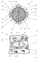
- the Fig. 7 shows a mounting kit according to the invention for the simplified installation of a domestic hot water appliance, such. B. a water heater, in which this is to be connected to a wall nipple, which carries a fluid.
- a mounting kit 110 includes in addition to the connector 10 of the invention a plurality of other components 112, such.
- components 112 As screws, bolts, washers, fan discs, dowels, threaded nipples, spacers, threaded sleeves, sleeves, supports, grommets, adapters, sealing rings, sealants, sieves, inserts, auxiliary tools, etc., for the professional wall connection of a household appliance, in particular a water heater, necessary to a wall nipple.
- the components 112 are contained in a packaging 114, which by way of example is a preferably transparent foil bag 116, a paper bag or the like.
- an additional packaging 120 which is formed here with a transparent sticker 122 which serves to fix the position of at least one further flow restrictor 124 on the outside of the package 114.
- the flow restrictor 124 is first applied to a rear side of the sticker 122 for this purpose.
- the package 114 and the film bag 116 facing the back of the sticker is this at least partially adhesive or self-adhesive equipped or provided with a suitable adhesive.
- the sticker 122 is stuck together with the flow restrictor 124 adhering thereto on the outside of the package 114.
- the packaging 114 and / or the transparent sticker 122 are preferably provided with assembly instructions 126 in textual and / or iconic form.
- both the packaging 114 and the label 122 which is at least partially adhesive or self-adhesive, are preferably formed at least partially with a transparent plastic material.
Landscapes
- Engineering & Computer Science (AREA)
- Chemical & Material Sciences (AREA)
- Physics & Mathematics (AREA)
- Thermal Sciences (AREA)
- Combustion & Propulsion (AREA)
- Mechanical Engineering (AREA)
- General Engineering & Computer Science (AREA)
- Chemical Kinetics & Catalysis (AREA)
- Filtration Of Liquid (AREA)
- Taps Or Cocks (AREA)
- Quick-Acting Or Multi-Walled Pipe Joints (AREA)
- Valve Housings (AREA)
Applications Claiming Priority (1)
| Application Number | Priority Date | Filing Date | Title |
|---|---|---|---|
| DE102013211188.6A DE102013211188A1 (de) | 2013-06-14 | 2013-06-14 | Anschlussstück sowie Montagesatz |
Publications (3)
| Publication Number | Publication Date |
|---|---|
| EP2821730A2 true EP2821730A2 (fr) | 2015-01-07 |
| EP2821730A3 EP2821730A3 (fr) | 2015-04-01 |
| EP2821730B1 EP2821730B1 (fr) | 2016-08-17 |
Family
ID=50897415
Family Applications (1)
| Application Number | Title | Priority Date | Filing Date |
|---|---|---|---|
| EP14171302.4A Not-in-force EP2821730B1 (fr) | 2013-06-14 | 2014-06-05 | Pièce de raccordement et ensemble de montage |
Country Status (3)
| Country | Link |
|---|---|
| EP (1) | EP2821730B1 (fr) |
| DE (1) | DE102013211188A1 (fr) |
| PL (1) | PL2821730T3 (fr) |
Cited By (2)
| Publication number | Priority date | Publication date | Assignee | Title |
|---|---|---|---|---|
| CN104831503A (zh) * | 2015-04-27 | 2015-08-12 | 浙江沁园水处理科技有限公司 | 带过滤装置的洗衣机及其过滤装置 |
| CN110396806A (zh) * | 2019-06-27 | 2019-11-01 | 无锡小天鹅电器有限公司 | 管线限位件、底座组件以及衣物处理设备 |
Families Citing this family (1)
| Publication number | Priority date | Publication date | Assignee | Title |
|---|---|---|---|---|
| US11287160B2 (en) * | 2017-07-21 | 2022-03-29 | Rheem Manufacturing Company | Water heater inlet fitting, flow sensor, shut off valve and diffuser |
Citations (2)
| Publication number | Priority date | Publication date | Assignee | Title |
|---|---|---|---|---|
| DE4326352C2 (de) | 1993-08-05 | 1996-07-11 | Bosch Siemens Hausgeraete | Fluid-Kanalvorrichtung für Haushaltgeräte |
| DE19919910B4 (de) | 1999-04-30 | 2008-04-17 | BSH Bosch und Siemens Hausgeräte GmbH | Vorrichtung mit zumindest einem Fluidkanal |
Family Cites Families (7)
| Publication number | Priority date | Publication date | Assignee | Title |
|---|---|---|---|---|
| DE2522443A1 (de) * | 1975-05-21 | 1976-12-02 | Schell Kg Hubert | Wasserschadenschutzventil |
| DE3537186A1 (de) * | 1985-10-18 | 1987-04-23 | Bosch Siemens Hausgeraete | Sicherheitsvorrichtung gegen ueberschwemmung bei fluessigkeitsfuehrenden haushaltgeraeten |
| DE3618738A1 (de) * | 1986-06-04 | 1987-12-10 | Bosch Siemens Hausgeraete | Sicherheitsvorrichtung gegen ueberschwemmung bei wasserfuehrenden haushaltgeraeten, insb. geschirrspuel- und waschmaschinen |
| US6402962B1 (en) * | 2000-07-26 | 2002-06-11 | Maytag Corporation | Self-cleaning filter with bypass |
| DE202005008766U1 (de) * | 2005-06-02 | 2005-08-04 | Electrolux Home Products Corporation N.V. | Wasseranschluss mit Siebfilter und wasserführendes Haushaltsgerät |
| ITTO20050876A1 (it) * | 2005-12-15 | 2007-06-16 | Eltek Spa | Dispositivo di sicurezza antiallagamento per elettrodomestici, in particolare macchine di lavaggio |
| US20080314466A1 (en) * | 2007-06-22 | 2008-12-25 | Cimberio Valve Co. Inc. | Valves for use with tankless water heater |
-
2013
- 2013-06-14 DE DE102013211188.6A patent/DE102013211188A1/de not_active Ceased
-
2014
- 2014-06-05 PL PL14171302T patent/PL2821730T3/pl unknown
- 2014-06-05 EP EP14171302.4A patent/EP2821730B1/fr not_active Not-in-force
Patent Citations (2)
| Publication number | Priority date | Publication date | Assignee | Title |
|---|---|---|---|---|
| DE4326352C2 (de) | 1993-08-05 | 1996-07-11 | Bosch Siemens Hausgeraete | Fluid-Kanalvorrichtung für Haushaltgeräte |
| DE19919910B4 (de) | 1999-04-30 | 2008-04-17 | BSH Bosch und Siemens Hausgeräte GmbH | Vorrichtung mit zumindest einem Fluidkanal |
Cited By (2)
| Publication number | Priority date | Publication date | Assignee | Title |
|---|---|---|---|---|
| CN104831503A (zh) * | 2015-04-27 | 2015-08-12 | 浙江沁园水处理科技有限公司 | 带过滤装置的洗衣机及其过滤装置 |
| CN110396806A (zh) * | 2019-06-27 | 2019-11-01 | 无锡小天鹅电器有限公司 | 管线限位件、底座组件以及衣物处理设备 |
Also Published As
| Publication number | Publication date |
|---|---|
| PL2821730T3 (pl) | 2017-02-28 |
| EP2821730B1 (fr) | 2016-08-17 |
| EP2821730A3 (fr) | 2015-04-01 |
| DE102013211188A1 (de) | 2014-12-18 |
Similar Documents
| Publication | Publication Date | Title |
|---|---|---|
| EP2753853B1 (fr) | Mitigeur à levier unique pour un lavabo | |
| EP2479462B1 (fr) | Armature sanitaire antigel | |
| EP3139074B1 (fr) | Armature exterieure protegee contre le gel et son procede de montage | |
| EP2821730B1 (fr) | Pièce de raccordement et ensemble de montage | |
| EP3105380B1 (fr) | Robinet à bec pivotant | |
| EP3105381B1 (fr) | Robinet à bec pivotant | |
| EP2770235B1 (fr) | Appareil de sectionnement | |
| EP2515021A2 (fr) | Agencement de filtre de réduction de pression doté d'une protection anti-fuites | |
| EP1546615B1 (fr) | Adaptateur de raccordement pour radiateur | |
| DE202017104365U1 (de) | Druckminderer-Filter-Anordnung | |
| WO2008067988A1 (fr) | Armature de verrouillage à compensation de longueur | |
| DE19854848B4 (de) | Anschlusseinrichtung für Heizkörper | |
| EP4450720A1 (fr) | Robinetterie de sortie résistante au gel et boîtier de sortie d'une robinetterie | |
| EP3418436B1 (fr) | Dispositif de tuyau et agencement | |
| EP1837575B1 (fr) | Raccord pour des tuyaux avec un joint d'étanchéité gonflable | |
| EP3627028B1 (fr) | Raccord | |
| DE102005008398B4 (de) | Anbohrarmatur für Kunststoffrohre und Verfahren zum Anschließen einer Anbohrarmatur | |
| DE2036217A1 (de) | Anschlußteil an einem Leitungssystem | |
| DE10115198C1 (de) | Anschlußanordnung für eine Wasser-Armatur | |
| DE102015011658A1 (de) | Sanitärarmatur mit wasserführenden Schlauch | |
| DE102007004717B3 (de) | Anschlussarmatur für eine flüssigkeitsführende Anordnung, insbesondere eine Heizkörperanordnung | |
| DE202018104831U1 (de) | Druckminderer-Anordnung | |
| DE102008048137B4 (de) | Verschlusskupplung | |
| DE202024107441U1 (de) | Verbindung für wasserführende Bauteile | |
| DE102010048382B4 (de) | Korrosionsgeschützte Armatur |
Legal Events
| Date | Code | Title | Description |
|---|---|---|---|
| PUAI | Public reference made under article 153(3) epc to a published international application that has entered the european phase |
Free format text: ORIGINAL CODE: 0009012 |
|
| 17P | Request for examination filed |
Effective date: 20140605 |
|
| AK | Designated contracting states |
Kind code of ref document: A2 Designated state(s): AL AT BE BG CH CY CZ DE DK EE ES FI FR GB GR HR HU IE IS IT LI LT LU LV MC MK MT NL NO PL PT RO RS SE SI SK SM TR |
|
| AX | Request for extension of the european patent |
Extension state: BA ME |
|
| PUAL | Search report despatched |
Free format text: ORIGINAL CODE: 0009013 |
|
| RAP1 | Party data changed (applicant data changed or rights of an application transferred) |
Owner name: BSH HAUSGERAETE GMBH |
|
| AK | Designated contracting states |
Kind code of ref document: A3 Designated state(s): AL AT BE BG CH CY CZ DE DK EE ES FI FR GB GR HR HU IE IS IT LI LT LU LV MC MK MT NL NO PL PT RO RS SE SI SK SM TR |
|
| AX | Request for extension of the european patent |
Extension state: BA ME |
|
| RIC1 | Information provided on ipc code assigned before grant |
Ipc: B01D 29/00 20060101ALI20150226BHEP Ipc: E03B 7/07 20060101ALI20150226BHEP Ipc: B01D 35/02 20060101ALI20150226BHEP Ipc: F24D 3/10 20060101ALI20150226BHEP Ipc: A47L 15/42 20060101ALI20150226BHEP Ipc: F24H 9/12 20060101AFI20150226BHEP Ipc: D06F 39/10 20060101ALI20150226BHEP |
|
| R17P | Request for examination filed (corrected) |
Effective date: 20151001 |
|
| RBV | Designated contracting states (corrected) |
Designated state(s): AL AT BE BG CH CY CZ DE DK EE ES FI FR GB GR HR HU IE IS IT LI LT LU LV MC MK MT NL NO PL PT RO RS SE SI SK SM TR |
|
| GRAP | Despatch of communication of intention to grant a patent |
Free format text: ORIGINAL CODE: EPIDOSNIGR1 |
|
| INTG | Intention to grant announced |
Effective date: 20160317 |
|
| GRAS | Grant fee paid |
Free format text: ORIGINAL CODE: EPIDOSNIGR3 |
|
| GRAA | (expected) grant |
Free format text: ORIGINAL CODE: 0009210 |
|
| AK | Designated contracting states |
Kind code of ref document: B1 Designated state(s): AL AT BE BG CH CY CZ DE DK EE ES FI FR GB GR HR HU IE IS IT LI LT LU LV MC MK MT NL NO PL PT RO RS SE SI SK SM TR |
|
| REG | Reference to a national code |
Ref country code: GB Ref legal event code: FG4D Free format text: NOT ENGLISH |
|
| REG | Reference to a national code |
Ref country code: CH Ref legal event code: EP |
|
| REG | Reference to a national code |
Ref country code: IE Ref legal event code: FG4D Free format text: LANGUAGE OF EP DOCUMENT: GERMAN |
|
| REG | Reference to a national code |
Ref country code: AT Ref legal event code: REF Ref document number: 821498 Country of ref document: AT Kind code of ref document: T Effective date: 20160915 |
|
| REG | Reference to a national code |
Ref country code: DE Ref legal event code: R096 Ref document number: 502014001251 Country of ref document: DE |
|
| REG | Reference to a national code |
Ref country code: NL Ref legal event code: MP Effective date: 20160817 |
|
| REG | Reference to a national code |
Ref country code: LT Ref legal event code: MG4D |
|
| PG25 | Lapsed in a contracting state [announced via postgrant information from national office to epo] |
Ref country code: NO Free format text: LAPSE BECAUSE OF FAILURE TO SUBMIT A TRANSLATION OF THE DESCRIPTION OR TO PAY THE FEE WITHIN THE PRESCRIBED TIME-LIMIT Effective date: 20161117 Ref country code: HR Free format text: LAPSE BECAUSE OF FAILURE TO SUBMIT A TRANSLATION OF THE DESCRIPTION OR TO PAY THE FEE WITHIN THE PRESCRIBED TIME-LIMIT Effective date: 20160817 Ref country code: LT Free format text: LAPSE BECAUSE OF FAILURE TO SUBMIT A TRANSLATION OF THE DESCRIPTION OR TO PAY THE FEE WITHIN THE PRESCRIBED TIME-LIMIT Effective date: 20160817 Ref country code: FI Free format text: LAPSE BECAUSE OF FAILURE TO SUBMIT A TRANSLATION OF THE DESCRIPTION OR TO PAY THE FEE WITHIN THE PRESCRIBED TIME-LIMIT Effective date: 20160817 Ref country code: RS Free format text: LAPSE BECAUSE OF FAILURE TO SUBMIT A TRANSLATION OF THE DESCRIPTION OR TO PAY THE FEE WITHIN THE PRESCRIBED TIME-LIMIT Effective date: 20160817 Ref country code: IT Free format text: LAPSE BECAUSE OF FAILURE TO SUBMIT A TRANSLATION OF THE DESCRIPTION OR TO PAY THE FEE WITHIN THE PRESCRIBED TIME-LIMIT Effective date: 20160817 Ref country code: NL Free format text: LAPSE BECAUSE OF FAILURE TO SUBMIT A TRANSLATION OF THE DESCRIPTION OR TO PAY THE FEE WITHIN THE PRESCRIBED TIME-LIMIT Effective date: 20160817 |
|
| PG25 | Lapsed in a contracting state [announced via postgrant information from national office to epo] |
Ref country code: SE Free format text: LAPSE BECAUSE OF FAILURE TO SUBMIT A TRANSLATION OF THE DESCRIPTION OR TO PAY THE FEE WITHIN THE PRESCRIBED TIME-LIMIT Effective date: 20160817 Ref country code: GR Free format text: LAPSE BECAUSE OF FAILURE TO SUBMIT A TRANSLATION OF THE DESCRIPTION OR TO PAY THE FEE WITHIN THE PRESCRIBED TIME-LIMIT Effective date: 20161118 Ref country code: ES Free format text: LAPSE BECAUSE OF FAILURE TO SUBMIT A TRANSLATION OF THE DESCRIPTION OR TO PAY THE FEE WITHIN THE PRESCRIBED TIME-LIMIT Effective date: 20160817 Ref country code: LV Free format text: LAPSE BECAUSE OF FAILURE TO SUBMIT A TRANSLATION OF THE DESCRIPTION OR TO PAY THE FEE WITHIN THE PRESCRIBED TIME-LIMIT Effective date: 20160817 Ref country code: PT Free format text: LAPSE BECAUSE OF FAILURE TO SUBMIT A TRANSLATION OF THE DESCRIPTION OR TO PAY THE FEE WITHIN THE PRESCRIBED TIME-LIMIT Effective date: 20161219 |
|
| PG25 | Lapsed in a contracting state [announced via postgrant information from national office to epo] |
Ref country code: RO Free format text: LAPSE BECAUSE OF FAILURE TO SUBMIT A TRANSLATION OF THE DESCRIPTION OR TO PAY THE FEE WITHIN THE PRESCRIBED TIME-LIMIT Effective date: 20160817 Ref country code: EE Free format text: LAPSE BECAUSE OF FAILURE TO SUBMIT A TRANSLATION OF THE DESCRIPTION OR TO PAY THE FEE WITHIN THE PRESCRIBED TIME-LIMIT Effective date: 20160817 |
|
| REG | Reference to a national code |
Ref country code: DE Ref legal event code: R097 Ref document number: 502014001251 Country of ref document: DE |
|
| PG25 | Lapsed in a contracting state [announced via postgrant information from national office to epo] |
Ref country code: SK Free format text: LAPSE BECAUSE OF FAILURE TO SUBMIT A TRANSLATION OF THE DESCRIPTION OR TO PAY THE FEE WITHIN THE PRESCRIBED TIME-LIMIT Effective date: 20160817 Ref country code: SM Free format text: LAPSE BECAUSE OF FAILURE TO SUBMIT A TRANSLATION OF THE DESCRIPTION OR TO PAY THE FEE WITHIN THE PRESCRIBED TIME-LIMIT Effective date: 20160817 Ref country code: BG Free format text: LAPSE BECAUSE OF FAILURE TO SUBMIT A TRANSLATION OF THE DESCRIPTION OR TO PAY THE FEE WITHIN THE PRESCRIBED TIME-LIMIT Effective date: 20161117 Ref country code: DK Free format text: LAPSE BECAUSE OF FAILURE TO SUBMIT A TRANSLATION OF THE DESCRIPTION OR TO PAY THE FEE WITHIN THE PRESCRIBED TIME-LIMIT Effective date: 20160817 Ref country code: CZ Free format text: LAPSE BECAUSE OF FAILURE TO SUBMIT A TRANSLATION OF THE DESCRIPTION OR TO PAY THE FEE WITHIN THE PRESCRIBED TIME-LIMIT Effective date: 20160817 |
|
| REG | Reference to a national code |
Ref country code: FR Ref legal event code: PLFP Year of fee payment: 4 |
|
| PLBE | No opposition filed within time limit |
Free format text: ORIGINAL CODE: 0009261 |
|
| STAA | Information on the status of an ep patent application or granted ep patent |
Free format text: STATUS: NO OPPOSITION FILED WITHIN TIME LIMIT |
|
| 26N | No opposition filed |
Effective date: 20170518 |
|
| PGFP | Annual fee paid to national office [announced via postgrant information from national office to epo] |
Ref country code: FR Payment date: 20170621 Year of fee payment: 4 |
|
| PG25 | Lapsed in a contracting state [announced via postgrant information from national office to epo] |
Ref country code: SI Free format text: LAPSE BECAUSE OF FAILURE TO SUBMIT A TRANSLATION OF THE DESCRIPTION OR TO PAY THE FEE WITHIN THE PRESCRIBED TIME-LIMIT Effective date: 20160817 |
|
| PGFP | Annual fee paid to national office [announced via postgrant information from national office to epo] |
Ref country code: PL Payment date: 20170525 Year of fee payment: 4 |
|
| PGFP | Annual fee paid to national office [announced via postgrant information from national office to epo] |
Ref country code: DE Payment date: 20170630 Year of fee payment: 4 |
|
| PG25 | Lapsed in a contracting state [announced via postgrant information from national office to epo] |
Ref country code: MC Free format text: LAPSE BECAUSE OF FAILURE TO SUBMIT A TRANSLATION OF THE DESCRIPTION OR TO PAY THE FEE WITHIN THE PRESCRIBED TIME-LIMIT Effective date: 20160817 |
|
| REG | Reference to a national code |
Ref country code: CH Ref legal event code: PL |
|
| REG | Reference to a national code |
Ref country code: IE Ref legal event code: MM4A |
|
| PG25 | Lapsed in a contracting state [announced via postgrant information from national office to epo] |
Ref country code: LI Free format text: LAPSE BECAUSE OF NON-PAYMENT OF DUE FEES Effective date: 20170630 Ref country code: LU Free format text: LAPSE BECAUSE OF NON-PAYMENT OF DUE FEES Effective date: 20170605 Ref country code: IE Free format text: LAPSE BECAUSE OF NON-PAYMENT OF DUE FEES Effective date: 20170605 Ref country code: CH Free format text: LAPSE BECAUSE OF NON-PAYMENT OF DUE FEES Effective date: 20170630 |
|
| REG | Reference to a national code |
Ref country code: BE Ref legal event code: MM Effective date: 20170630 |
|
| PG25 | Lapsed in a contracting state [announced via postgrant information from national office to epo] |
Ref country code: BE Free format text: LAPSE BECAUSE OF NON-PAYMENT OF DUE FEES Effective date: 20170630 |
|
| PG25 | Lapsed in a contracting state [announced via postgrant information from national office to epo] |
Ref country code: MT Free format text: LAPSE BECAUSE OF FAILURE TO SUBMIT A TRANSLATION OF THE DESCRIPTION OR TO PAY THE FEE WITHIN THE PRESCRIBED TIME-LIMIT Effective date: 20160817 |
|
| PG25 | Lapsed in a contracting state [announced via postgrant information from national office to epo] |
Ref country code: AL Free format text: LAPSE BECAUSE OF FAILURE TO SUBMIT A TRANSLATION OF THE DESCRIPTION OR TO PAY THE FEE WITHIN THE PRESCRIBED TIME-LIMIT Effective date: 20160817 |
|
| REG | Reference to a national code |
Ref country code: DE Ref legal event code: R119 Ref document number: 502014001251 Country of ref document: DE |
|
| GBPC | Gb: european patent ceased through non-payment of renewal fee |
Effective date: 20180605 |
|
| PG25 | Lapsed in a contracting state [announced via postgrant information from national office to epo] |
Ref country code: GB Free format text: LAPSE BECAUSE OF NON-PAYMENT OF DUE FEES Effective date: 20180605 Ref country code: DE Free format text: LAPSE BECAUSE OF NON-PAYMENT OF DUE FEES Effective date: 20190101 Ref country code: FR Free format text: LAPSE BECAUSE OF NON-PAYMENT OF DUE FEES Effective date: 20180630 |
|
| PG25 | Lapsed in a contracting state [announced via postgrant information from national office to epo] |
Ref country code: HU Free format text: LAPSE BECAUSE OF FAILURE TO SUBMIT A TRANSLATION OF THE DESCRIPTION OR TO PAY THE FEE WITHIN THE PRESCRIBED TIME-LIMIT; INVALID AB INITIO Effective date: 20140605 |
|
| PG25 | Lapsed in a contracting state [announced via postgrant information from national office to epo] |
Ref country code: CY Free format text: LAPSE BECAUSE OF FAILURE TO SUBMIT A TRANSLATION OF THE DESCRIPTION OR TO PAY THE FEE WITHIN THE PRESCRIBED TIME-LIMIT Effective date: 20160817 |
|
| PG25 | Lapsed in a contracting state [announced via postgrant information from national office to epo] |
Ref country code: MK Free format text: LAPSE BECAUSE OF FAILURE TO SUBMIT A TRANSLATION OF THE DESCRIPTION OR TO PAY THE FEE WITHIN THE PRESCRIBED TIME-LIMIT Effective date: 20160817 |
|
| PG25 | Lapsed in a contracting state [announced via postgrant information from national office to epo] |
Ref country code: PL Free format text: LAPSE BECAUSE OF NON-PAYMENT OF DUE FEES Effective date: 20180605 |
|
| PG25 | Lapsed in a contracting state [announced via postgrant information from national office to epo] |
Ref country code: TR Free format text: LAPSE BECAUSE OF FAILURE TO SUBMIT A TRANSLATION OF THE DESCRIPTION OR TO PAY THE FEE WITHIN THE PRESCRIBED TIME-LIMIT Effective date: 20160817 |
|
| PG25 | Lapsed in a contracting state [announced via postgrant information from national office to epo] |
Ref country code: IS Free format text: LAPSE BECAUSE OF FAILURE TO SUBMIT A TRANSLATION OF THE DESCRIPTION OR TO PAY THE FEE WITHIN THE PRESCRIBED TIME-LIMIT Effective date: 20161217 |
|
| REG | Reference to a national code |
Ref country code: AT Ref legal event code: MM01 Ref document number: 821498 Country of ref document: AT Kind code of ref document: T Effective date: 20190605 |
|
| PG25 | Lapsed in a contracting state [announced via postgrant information from national office to epo] |
Ref country code: AT Free format text: LAPSE BECAUSE OF NON-PAYMENT OF DUE FEES Effective date: 20190605 |